WO2010146958A1 - トリポード型等速ジョイント - Google Patents
トリポード型等速ジョイント Download PDFInfo
- Publication number
- WO2010146958A1 WO2010146958A1 PCT/JP2010/058438 JP2010058438W WO2010146958A1 WO 2010146958 A1 WO2010146958 A1 WO 2010146958A1 JP 2010058438 W JP2010058438 W JP 2010058438W WO 2010146958 A1 WO2010146958 A1 WO 2010146958A1
- Authority
- WO
- WIPO (PCT)
- Prior art keywords
- tripod
- shaft portion
- constant velocity
- velocity joint
- torque transmission
- Prior art date
Links
Images


Classifications
-
- F—MECHANICAL ENGINEERING; LIGHTING; HEATING; WEAPONS; BLASTING
- F16—ENGINEERING ELEMENTS AND UNITS; GENERAL MEASURES FOR PRODUCING AND MAINTAINING EFFECTIVE FUNCTIONING OF MACHINES OR INSTALLATIONS; THERMAL INSULATION IN GENERAL
- F16D—COUPLINGS FOR TRANSMITTING ROTATION; CLUTCHES; BRAKES
- F16D3/00—Yielding couplings, i.e. with means permitting movement between the connected parts during the drive
- F16D3/16—Universal joints in which flexibility is produced by means of pivots or sliding or rolling connecting parts
- F16D3/20—Universal joints in which flexibility is produced by means of pivots or sliding or rolling connecting parts one coupling part entering a sleeve of the other coupling part and connected thereto by sliding or rolling members
- F16D3/202—Universal joints in which flexibility is produced by means of pivots or sliding or rolling connecting parts one coupling part entering a sleeve of the other coupling part and connected thereto by sliding or rolling members one coupling part having radially projecting pins, e.g. tripod joints
- F16D3/205—Universal joints in which flexibility is produced by means of pivots or sliding or rolling connecting parts one coupling part entering a sleeve of the other coupling part and connected thereto by sliding or rolling members one coupling part having radially projecting pins, e.g. tripod joints the pins extending radially outwardly from the coupling part
- F16D3/2055—Universal joints in which flexibility is produced by means of pivots or sliding or rolling connecting parts one coupling part entering a sleeve of the other coupling part and connected thereto by sliding or rolling members one coupling part having radially projecting pins, e.g. tripod joints the pins extending radially outwardly from the coupling part having three pins, i.e. true tripod joints
-
- F—MECHANICAL ENGINEERING; LIGHTING; HEATING; WEAPONS; BLASTING
- F16—ENGINEERING ELEMENTS AND UNITS; GENERAL MEASURES FOR PRODUCING AND MAINTAINING EFFECTIVE FUNCTIONING OF MACHINES OR INSTALLATIONS; THERMAL INSULATION IN GENERAL
- F16D—COUPLINGS FOR TRANSMITTING ROTATION; CLUTCHES; BRAKES
- F16D3/00—Yielding couplings, i.e. with means permitting movement between the connected parts during the drive
- F16D3/16—Universal joints in which flexibility is produced by means of pivots or sliding or rolling connecting parts
- F16D3/20—Universal joints in which flexibility is produced by means of pivots or sliding or rolling connecting parts one coupling part entering a sleeve of the other coupling part and connected thereto by sliding or rolling members
- F16D3/202—Universal joints in which flexibility is produced by means of pivots or sliding or rolling connecting parts one coupling part entering a sleeve of the other coupling part and connected thereto by sliding or rolling members one coupling part having radially projecting pins, e.g. tripod joints
- F16D2003/2026—Universal joints in which flexibility is produced by means of pivots or sliding or rolling connecting parts one coupling part entering a sleeve of the other coupling part and connected thereto by sliding or rolling members one coupling part having radially projecting pins, e.g. tripod joints with trunnion rings, i.e. with tripod joints having rollers supported by a ring on the trunnion
Definitions
- the present invention relates to a tripod constant velocity joint.
- Patent Document 1 As a tripod type constant velocity joint in which a roller member composed of an inner roller and an outer roller is fitted to a tripod shaft portion of a saddle tripod member, for example, one disclosed in Patent Document 1 is known.
- the torque transmission part of the tripod shaft part is formed in a spherical shape, so that the roller member can swing with respect to the tripod shaft part and can slide in the axial direction. Even if the angle (joint angle) formed by the rotation shafts of the input shaft and the output shaft is increased by swinging and sliding the roller member with respect to the tripod shaft portion, the extending direction of the outer race guide groove and the outer The rolling direction of the roller matches. Thereby, since an outer roller rotates smoothly with respect to an inner roller, the vibration at the time of torque transmission is suppressed.
- the present inventor has proposed the one described in Patent Document 2 as a further improvement of the tripod type constant velocity joint described in Patent Document 1.
- the axis orthogonal cross-sectional shape of the tripod shaft portion is a shape that continuously changes so that the root side of the torque transmission region is substantially circular, and becomes smaller and elliptical toward the tip side. By adopting such a shape, it is possible to increase the strength of the tripod constant velocity joint or reduce the size.
- FIG. 12A is a radial cross-sectional view of the tripod member of the tripod type constant velocity joint according to Patent Document 2 with respect to the rotation axis.
- This tripod type constant velocity joint includes a roller member 120 having an outer race 110, an outer roller 121 and an inner roller 122, a tripod member 130 having a boss portion 131 and a tripod shaft portion 132.
- the torque transmission surface 132a that contacts the inner roller 122 of the tripod shaft portion 132 has the longest distance from the central axis C of the tripod shaft portion 132 on the root side (lower side in the drawing), and the tip side (upper side in the drawing) of the tripod shaft portion 131. ) Is shorter as it goes to (d 10 > d 11 ).
- the inner peripheral surface of the inner roller 122 is formed in a cylindrical shape whose inner diameter is uniform in the axial direction.
- the contact region 123 is an ellipse that is long in the direction of the central axis of the inner roller 122 and has a shape with approximately half corresponding to the root side of the tripod shaft 132, and the surface pressure at the center of the ellipse is the highest. Becomes higher.
- one of the objects of the present invention is to provide a tripod constant velocity joint that can further reduce the surface pressure in the contact area between the tripod shaft portion and the inner roller during torque transmission and can be downsized. That is.
- a tripod constant velocity joint is configured as follows. That is, the tripod shaft portion has a torque transmission surface having a curved shape whose distance from the central axis becomes shorter from the root side toward the tip side, and the roller member is directed from the root side of the tripod shaft portion toward the tip side.
- the torque transmission surface is brought into contact with a contact surface having a smaller inner diameter.
- the contact surface pressure at the time of torque transmission of the tripod type constant velocity joint can be reduced.
- FIG. 1 is a partial cross-sectional view for explaining the entire tripod type constant velocity joint according to the embodiment of the present invention.
- FIG. 2 is a partial cross-sectional view for explaining the entire tripod type constant velocity joint according to the embodiment of the present invention.
- FIG. 3 is a cross-sectional view of the tripod member of the tripod constant velocity joint according to the embodiment of the present invention.
- FIG. 4 is an external view of a tripod member of the tripod type constant velocity joint according to the embodiment of the present invention.
- FIG. 5 is a cross-sectional view of the tripod shaft portion of the tripod type constant velocity joint according to the embodiment of the present invention.
- FIG. 6 is a perspective view of a tripod member of the tripod type constant velocity joint according to the embodiment of the present invention.
- FIG. 7 is a cross-sectional view of a roller member of the tripod type constant velocity joint according to the embodiment of the present invention.
- FIG. 8 is an explanatory view showing an assembled state of the tripod type constant velocity joint according to the embodiment of the present invention.
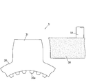
- FIG. 9 is an explanatory view showing a method for manufacturing a tripod member of the tripod type constant velocity joint according to the embodiment of the present invention.
- FIG. 10 is an explanatory view for explaining the effect of the tripod type constant velocity joint according to the embodiment of the present invention.
- FIG. 11 is a view showing a modification of the inner roller of the tripod type constant velocity joint of the present invention.
- FIG. 12A is a cross-sectional view of a conventional tripod constant velocity joint.
- FIG. 12B represents a contact area with a tripod shaft portion shown by cutting a part of an inner roller of a conventional tripod type constant velocity joint.
- FIG. 1 shows a state where the tripod constant velocity joint 1 is viewed from the direction of the rotation axis O1 and the rotation axis O2 in a state where the rotation axis O1 of the outer race 2 and the rotation axis O2 of the tripod member 3 coincide with each other.
- one of the three roller members 4 is shown cut by a cross section along the central axis of the roller member 4.
- FIG. 2 shows a state where a part of the tripod type constant velocity joint 1 is cut along a cross section along the rotation axis O1.
- a tripod type constant velocity joint 1 shown in FIGS. 1 and 2 is disposed, for example, on a wheel side of a differential device of a vehicle, and includes a first driving force transmission member that transmits torque of a driving source in a forward direction and a reverse direction. It is used for connecting the second driving force transmission member so as to be swingable and slidable in the axial direction.
- This tripod type constant velocity joint 1 is integrally rotated with an outer race 2 connected to rotate integrally with a first driving force transmission member (not shown) and a second driving force transmission member (not shown).
- the roller member 4 interposed between the outer race 2 and the tripod member 3.
- the roller member 4 is fitted to the tripod shaft portion 31 so as to be swingable.
- the roller member 4 is relatively slidable along the tripod shaft portion 31 (torque transmission surface 31c).
- the outer race 2 has a bottomed cylindrical shape as a whole, a hollow cylindrical portion 20 in which a space is formed inside, a bottom portion 21 that closes one end of the cylindrical portion 20, and a bottom portion 21. It comprises a shaft portion 22 erected on the opposite side of the tube portion 20.
- a first driving force transmission member is coupled to the shaft portion 22 so as to rotate integrally by a known means such as spline fitting.
- Three pairs of guide grooves 20 a and 20 b are formed on the inner peripheral surface of the flanged cylinder portion 20 as guide surfaces that extend in a direction parallel to the rotation axis O ⁇ b> 1 of the outer race 2 to form a pair.
- the guide groove 20a and the guide groove 20b are opposed to each other with the roller member 4 interposed therebetween.
- the roller member 4 and the guide groove 20a or the guide groove 20b transmit torque by angular contact at two points during torque transmission.
- the guide groove 20a and the guide groove 20b guide the roller member 4 in a direction along the rotation axis O1.
- the tripod member 3 is formed in an annular boss portion 30 in which a shaft-like second driving force transmission member (not shown) is spline-fitted to the inner surface and radially formed at equal intervals on the outer peripheral side of the boss portion 30. It consists of three tripod shafts 31. A spline portion 30 a that engages with the second driving force transmission member is formed on the inner surface of the through hole provided in the boss portion 30.
- the tripod member 3 is disposed inside the cylindrical portion 20 of the outer race 2, and the roller member 4 is fitted to each tripod shaft portion 31 so as to be swingable and slidable.
- FIG. 3 is a longitudinal sectional view of the tripod shaft portion 31 cut along a cross section including the central axis C1 and orthogonal to the rotation axis O2 of the tripod member 3.
- the tripod shaft part 31 has a straight part 31a formed on the base side (the boss part 30 side) and a curved part 31b formed on the tip side continuously to the straight part 31a.
- the tripod shaft portion 31 is formed symmetrically with respect to the central axis C1, and a straight portion 31a and a curved portion 31b are formed on the right side of the tripod shaft portion 31 in the same manner.
- the heel straight part 31a is a part formed in parallel to the central axis C1.
- the curved portion 31b is a portion formed in a curved shape in which the distance d from the central axis C1 to the outer peripheral surface gradually decreases from the root side toward the tip side.
- the amount of change in the distance d with respect to the width in the direction of the central axis C ⁇ b> 1 increases toward the tip side of the tripod shaft portion 31. That is, the curvature of the curved portion 31b is small on the base side, increases as it approaches the front end side, and increases most near the front end surface 31d.
- the curved portion 31b of the tripod shaft portion 31 has a curved shape that bulges outward, and more specifically, is formed by an involute curve.
- the saddle tripod shaft portion 31 has a torque transmission surface 31 c that abuts on the inner peripheral surface of the inner roller 42 constituting the roller member 4 and transmits torque.
- the torque transmission surface 31c is a region where contact with the inner peripheral surface of the inner roller 42 can occur in the actual use state where the tripod type constant velocity joint 1 is incorporated in a vehicle or the like.
- the torque transmission surface 31c consists of a part of the curved part 31b.
- the torque transmission surface 31c is a region having a spread in the circumferential direction of the central axis C1 around the both ends of the tripod shaft 31 in the torque transmission direction.
- the radius of curvature of the torque transmission surface 31c in the cross section along the central axis C1 is greater than the distance (d 1 ) from the central axis C1 of the root side end of the torque transmission surface 31c in the entire region. Furthermore, the radius of curvature of the torque transmission surface 31c is greater than the distance (d 0 ) from the central axis C1 of the linear portion 31a in the entire region. That is, the radius of curvature in the longitudinal section of the torque transmission surface 31c is formed larger than when the torque transmission portion of the tripod shaft portion is formed in a spherical shape as in the tripod type constant velocity joint according to Patent Document 1, for example. Thereby, the surface pressure at the time of torque transmission is reduced.
- FIG. 4 is a diagram showing the appearance of the tripod member 3 viewed from the direction of the central axis C1 of the tripod shaft portion 31 by a solid line, and the inner peripheral surface of the inner roller 42 by a broken line.
- the tripod shaft portion 31 has a width in the direction of the rotation axis O2 of the tripod member 3 in the direction q in FIG. 4 perpendicular to the rotation axis O2 and the center axis C1 (hereinafter referred to as “torque transmission direction”). ).
- torque transmission direction hereinafter referred to as “torque transmission direction”.
- FIG. 5 is a diagram showing a contour line in a transverse section (AA section in FIG. 3) obtained by cutting a region including the torque transmission surface 31c of the tripod shaft portion 31 with a plane orthogonal to the central axis C1.
- An outline line of the cross section of the tripod shaft portion 31 is formed by four involute curves I1 to I4 and two line segments S1 and S2 connecting between the involute curves I1 to I4.
- the curvatures of the involute curves I1 to I4 gradually increase from the start point R1 toward the end point R2.
- the torque transmission surface 31c in the cross section of the tripod shaft 31 has the smallest curvature at the end in the torque transmission direction.
- the curvature gradually increases as the distance from the part increases.
- FIG. 6 is a perspective view of one of the tripod shaft portions 31 of the tripod member 3 as seen from an oblique direction.
- the tripod shaft part 31 is formed so that the whole becomes narrower from the root side toward the tip side, and there is no portion that becomes thicker from the root side toward the tip part in every cross section parallel to the central axis C1.
- FIG. 7 is a view showing a cross section of the roller member 4 cut along a plane along the center line C2.
- the roller member 4 is disposed between the outer roller 41 and the inner roller 42, an outer roller 41 having an outer peripheral surface facing the guide grooves 20 a and 20 b of the outer race 2, an inner roller 42 coaxially disposed inside the outer roller 41, and the outer roller 41.
- a plurality of rolling elements 43 are annular, and the roller member 4 is also annular.
- the rolling element 43 needle rollers are employed.
- a ridge portion 41a protruding inward is formed on one side in the axial direction of the heel outer roller 41.
- the inner diameter of the flange 41a is formed smaller than the outer diameter of the inner roller 42, and the axial movement of the inner roller 42 and the rolling element 43 is restricted.
- a snap ring 44 is fitted on the other side of the outer roller 41 in the axial direction, and the axial movement of the inner roller 42 and the rolling element 43 is restricted by the snap ring 44.
- a first tapered portion 42 a and a second taper are formed from the outer end surface 421 positioned on the outer peripheral side of the outer race 2 toward the inner end surface 422 on the opposite side when the inner roller 42 is assembled.
- Three tapered portions of the tapered portion 42b and the third tapered portion 42c are formed continuously.
- the second tapered portion 42 b transmits torque by contacting the torque transmitting surface 31 c of the tripod shaft portion 31.
- the second tapered portion 42b corresponds to the contact surface of the present invention.
- the first taper portion 42a and the third taper portion 42c are formed to avoid unnecessary interference between the inner roller 42 and the tripod member 3, and do not directly contribute to torque transmission.
- the second taper portion 42b is linear in the cross section shown in FIG. 7, and its curvature is zero.
- the first taper portion 42a is formed in a conical shape whose diameter increases toward the opening on the outer end surface 421 side.
- the angle (conical angle) between the conical surface and the central axis C2 is set to 5 °.
- the second taper portion 42b is formed in a conical shape whose inner diameter decreases from the inner end surface 422 side (the base side of the tripod shaft portion 31) toward the outer end surface 421 side (the tip end side of the tripod shaft portion 31). Yes.
- the cone angle of the conical surface is set to an angle corresponding to the curvature of the torque transmission surface 31c. More specifically, the conical angle of the second taper portion 42b is larger than the angle formed by the tangent TL1 at the tip side end portion of the torque transmission surface 31c with the central axis C1 in the cross-sectional view of the tripod shaft portion 31 shown in FIG.
- the tangent line TL2 at the base side end of the torque transmission surface 31c is larger than the angle formed with the central axis C1.
- the saddle tripod shaft portion 31 and the inner roller 42 are preferably formed such that the cone angle of the second taper portion 42b is 0.5 ° or more. This is because if the angle is less than 0.5 °, the effects of the present invention described later cannot be sufficiently achieved.
- the cone angle is desirably set to 5 ° or less. If the angle exceeds 5 °, the roller member 4 is likely to be press-fitted into the tripod shaft portion 31 when the tripod type constant velocity joint 1 is assembled, and the assembly may be hindered.
- a more preferable range of the cone angle is 0.7 ° or more and 3 ° or less. If it is this range, while being able to show
- the cone angle is set to 1 °. In each drawing such as FIG. 7, for the sake of explanation, the cone angle of the second taper portion 42 b is exaggerated.
- the third taper portion 42c is formed in a conical shape whose diameter increases toward the opening on the inner end surface 422 side.
- the cone angle of the conical surface is set to an angle (for example, 20 °) larger than the cone angle of the second taper portion 42b.
- FIG. 8 is a view of the tripod type constant velocity joint 1 in a state where the joint angle is zero as viewed from the direction of the rotation axis O2 of the tripod member 3.
- the distance r between the rotation axis O2 and the straight line L1 connecting the boundary between the linear portion 31a and the curved portion 31b of the torque transmission surface 31c on both sides of the torque transmission direction of the tripod shaft portion 31 is the guide groove 20a in the outer peripheral surface of the outer roller 41.
- the distance PCR is shorter than the distance PCR between the rotation axis O2 and the straight line L2 connecting the axial center of the region that contacts the guide groove 20b and transmits torque. Thereby, even when the joint angle is taken, the roller member 4 and the tripod member 3 can swing smoothly.
- the process of forming the tripod member 3 includes a forging process and a grinding process.
- the forging step is a step of forging the material and processing it into a shape in which three tripod shaft portions 31 are erected outside the boss portion 30.
- a recess corresponding to the shape of the tripod shaft portion 31 is formed.
- the tripod shaft 31 is roughly molded by applying a pressure to the material and plastically flowing in accordance with the shape of the recess.
- the scissor grinding step is a step of grinding the outer peripheral surface of the tripod shaft portion 31 and processing it with high accuracy. The grinding process will be described in detail below.
- FIG. 9 is a diagram showing the tripod member 3 and the grindstone 50 in the grinding process.
- the outer peripheral surface of the grindstone 50 used in the grinding process has a shape corresponding to the finished shape of the vertical section of the tripod shaft portion 31.
- the grindstone 50 is pressed around the outer peripheral surface of the tripod shaft portion 31 while rotating around the drive shaft 51, and the outer peripheral surface is ground by rotating around the tripod shaft portion 31.
- the tripod shaft portion 31 thus ground is parallel to the central axis C1 of the tripod shaft portion 31 and the outer peripheral surface of the cross section including the normal line at the ground portion is shown in FIG. Will draw a curve similar to
- the roller member 4 In the state where the joint angle is zero, as shown by the solid line in FIGS. 1 and 2, the roller member 4 is positioned on the base side of the tripod shaft portion 31, and torque transmission on one side of the tripod shaft portion 31 in the torque transmission direction is performed. The surface 31c and the second tapered portion 42b of the inner roller 42 come into contact with each other to transmit torque. In this state, even if the outer race 2 rotates, the tripod shaft portion 31 and the roller member 4 do not slide.
- the curvature of the torque transmission surface 31c is large at the tip side of the tripod shaft portion 31, the area of the contact region is smaller and the surface pressure is higher than when the joint angle is zero, but the torque transmission surface 31c is as described above. Is larger than the distance from the central axis C1 of the linear portion 31a, the surface pressure is suppressed as compared with the case where the tripod shaft portion is formed in a spherical shape as described in Patent Document 1, for example.
- a torque transmission surface 31c having a curved portion 31b that narrows toward the tip end side of the tripod shaft portion 31, and a second taper portion 42b of the inner roller 42 that also decreases in inner diameter toward the tip end side of the tripod shaft portion 31. And the torque is transmitted, so that the tripod shaft portion 31 and the inner roller 42 are in contact with each other over a wider area than when the inner peripheral surface of the inner roller 42 is cylindrical.
- FIG. 10 shows a contact region between the second tapered portion 42b and the torque transmission surface 31c when the inner peripheral surface of the inner roller 42 is viewed from the central axis C1 side of the tripod shaft portion 31 for explaining this effect.
- the contact area is more on the tip side of the tripod shaft portion 31 than when the inner peripheral surface of the inner roller is cylindrical ( Move to the upper side of the figure.
- region does not lack and both members contact in an elliptical contact area
- the surface pressure at the time of torque transmission can be reduced, and as a result, high strength, high durability, or downsizing can be realized.
- the second taper portion 42b of the inner roller 42 extends toward the base side of the tripod shaft portion 31, and a cone angle larger than the cone angle of the second taper portion 42b is formed on the inner end face 422 side of the second taper portion 42b.
- a third taper portion 42c having the shape is formed. That is, since the inner diameter of the inner peripheral surface of the inner roller 42 increases toward the base side of the tripod shaft portion 31, on the torque non-transmission side that does not transmit torque, on both sides of the torque transmission direction of the tripod shaft portion 31. Generation of contact between the tripod shaft portion 31 and the inner roller 42 can be suppressed.
- the roller member near the root of the tripod shaft portion 31 on the torque non-transmission side with the swing of the tripod member 3 with respect to the roller member 4. 4 may easily occur, and the occurrence of this contact may increase the resistance during swinging.
- contact on the torque non-transmission side can be avoided or contacted. Since the surface pressure of the contact portion can be lowered, the swing between the tripod member 3 and the roller member 4 becomes smoother.
- the tripod shaft portion 31 is thickest at the base side and becomes narrower toward the tip end portion, forging is easy and the life of the forging die is extended. That is, for example, when the tripod shaft portion is spherical like the tripod constant velocity joint described in Patent Document 1, it is necessary to flow the material so as to swell outward in the forging die, For this purpose, a large load is required, but in the processing of the tripod member 3 according to the present embodiment, forging can be performed with a relatively small load. Further, since the surface shape of the tripod shaft portion 31 is uniform in the longitudinal section along the central axis C1, it can be easily ground with a grindstone.
- the tripod type constant velocity joint of the present invention has been described based on the embodiments.
- the present invention is not limited to the above embodiments, and may be implemented in various modes without departing from the gist thereof.
- the following modifications are possible.
- the region that contacts the tripod shaft portion 31 on the inner peripheral surface of the inner roller 42 and transmits torque is not a conical surface having a linear cross section, but a curved surface having a curved cross section and bulging radially outward. Good.
- An example of forming the inner roller 42 in this way is shown in FIG.
- the contact surface that contacts the torque transmission surface 31c of the tripod shaft portion 31 is formed by a curved reduced diameter portion 42b1 whose inner diameter decreases from the inner end surface 422 side toward the outer end surface 421 side.
- the curvature of the curved reduced diameter portion 42b1 is formed larger than the curvature of the torque transmission surface 31c.
- the first tapered portion 42a of the inner roller 42 may not be provided.
- the second taper portion 42b or the curved reduced diameter portion 42b1 reaches the outer end surface 421 side.
- the entire part may be constituted by the curved part 31b.
- a tripod constant velocity joint is configured as follows. That is, the tripod shaft portion has a torque transmission surface having a curved shape whose distance from the central axis becomes shorter from the root side toward the tip side, and the roller member is directed from the root side of the tripod shaft portion toward the tip side.
- the torque transmission surface is brought into contact with a contact surface having a smaller inner diameter.
- the scissor roller member may be formed in a conical shape whose diameter is reduced toward the tip side of the tripod shaft portion, and the cone angle may be 0.5 degrees or more. Thereby, the effect of this invention can be show
- the saddle tripod shaft portion may be formed by a curved line having a curvature that increases from the root side toward the tip side in the shape of the torque transmission surface in the longitudinal section including the central axis.
- the curvature radius of the torque transmission surface in the longitudinal section of the tripod shaft portion is preferably larger than the distance between the root side end portion of the torque transmission surface and the center axis of the tripod shaft portion.
- the saddle tripod shaft portion preferably has a width in the rotation axis direction smaller than a width in the torque transmission direction in a cross section orthogonal to the central axis.
- An end surface corresponding to the base side of the tripod shaft portion of the roller member may be formed with an inclined surface having a larger inclination angle than the contact surface with the tripod shaft portion with respect to the central axis of the roller member and extending toward the root. . Thereby, unnecessary interference between the roller member and the tripod shaft portion can be avoided.
Abstract
トルク伝達時におけるトリポード部材の接触面圧を低減可能なトリポード型等速ジョイントを提供する。トリポード型等速ジョイント(1)は、中心軸(C1)からの距離が根元側から先端側に向かって短くなる湾曲形状のトルク伝達面(31c)を有する3つのトリポード軸部(31)が放射状に形成されたトリポード部材(3)と、トリポード軸部(31)に揺動可能に嵌合され、トルク伝達面(31c)に接触する接触面(42b)がトリポード軸部(31)の根元側から先端側に向かって内径が小さくなるように形成された環状のローラ部材(4)と、トリポード部材(3)及びローラ部材(4)を収容すると共にローラ部材(4)を回転軸(O1)方向に案内する案内溝(20a,20b)が形成された筒部(20)を有するアウターレース(2)とを備える。
Description
本発明は、トリポード型等速ジョイントに関するものである。
トリポード部材のトリポード軸部に、インナーローラ及びアウターローラからなるローラ部材を嵌合したトリポード型等速ジョイントとして、例えば特許文献1に記載のものが知られている。このトリポード型等速ジョイントでは、トリポード軸部のトルク伝達部を球状に形成することにより、トリポード軸部に対してローラ部材が揺動可能かつ軸方向に摺動可能となっている。トリポード軸部に対してローラ部材が揺動かつ摺動することで、入力軸及び出力軸の回転軸がなす角(ジョイント角)が大きくなった場合でも、アウターレースの案内溝の延伸方向とアウターローラの転動方向とが一致する。これにより、アウターローラがインナーローラに対して滑らかに回転するので、トルク伝達時の振動が抑制されている。
また、本発明者は、特許文献1に記載のトリポード型等速ジョイントをさらに改良したものとして、特許文献2に記載のものを提案している。このトリポード型等速ジョイントでは、トリポード軸部の軸直交断面形状を、トルク伝達領域の根元側がほぼ円形で、先端側に行くに従って小さく且つ楕円形状になるよう、連続的に変化する形状としている。このような形状を採用することにより、トリポード型等速ジョイントの強度を高くし、あるいは小型化することが可能となる。
図12Aは、上記特許文献2に係るトリポード型等速ジョイントのトリポード部材の回転軸に対する径方向断面図である。このトリポード型等速ジョイントは、アウターレース110、アウターローラ121及びインナーローラ122を有するローラ部材120、ボス部131及びトリポード軸部132を有するトリポード部材130を備えている。トリポード軸部132のインナーローラ122と接触するトルク伝達面132aは、トリポード軸部132の中心軸Cからの距離が根元側(図面下側)で最も長く、トリポード軸部131の先端側(図面上側)に行くに従って短くなっている(d10>d11)。インナーローラ122の内周面は、内径が軸方向に均一な円筒状に形成されている。
上記の構成を備えたトリポード型等速ジョイントでトルクを伝達する際、ジョイント角が小さい場合(例えば6°以下の場合)には、トリポード軸部132の根元側にあたるインナーローラ122の内周面の端部にて、インナーローラ122とトリポード軸部132との接触が発生する。図12Bに、図12Aのトリポード軸部132の中心軸Cから反時計側の回転方向(図面左方)を見た場合の、トルク伝達時におけるインナーローラ122のトリポード軸部132との接触領域123の一例を示す。この図に示すように、接触領域123は、インナーローラ122の中心軸方向に長い楕円の、トリポード軸部132の根元側にあたる約半分が欠けた形状であり、その楕円中心部にて最も面圧が高くなる。
この特許文献2に係るトリポード型等速ジョイントでは、例えば特許文献1に記載のもののようにトリポード軸部を球状に形成した場合に比べ、トルク伝達面132aの縦断面における曲率が小さいので、面圧を低減する一定の効果はある。しかし、上記のように接触領域123が理想的な楕円状とはならず、その一部が欠けてしまうため、この欠けが生じないとした場合に比べると、トルク伝達時の面圧が高くなってしまう。このため、その面圧に耐えられる大きさで各構成部材を設計しなければならないという点で、なお改善の余地があった。
そこで本発明の目的の一つは、トルク伝達時におけるトリポード軸部とインナーローラとの接触領域の面圧をより一層低減し、ひいては小型化を図ることが可能なトリポード型等速ジョイントを提供することである。
本発明の一態様では、以下のようにトリポード型等速ジョイントを構成する。すなわち、トリポード軸部は、その中心軸からの距離が根元側から先端側に向かって短くなる湾曲形状を有するトルク伝達面を有し、ローラ部材はトリポード軸部の根元側から先端側に向かって内径が小さくなる接触面で前記トルク伝達面に接触する。これにより、ローラ部材の内面が円筒状に形成された場合に比べ、トリポード軸部とローラ部材とがより広い面積で接触する。
本発明によれば、トリポード型等速ジョイントのトルク伝達時における接触部の面圧を低減できる。
本発明の実施の形態の一例につき、全体構成を図1及び図2を用いて説明する。図1は、アウターレース2の回転軸O1とトリポード部材3の回転軸O2が一致した状態におけるトリポード型等速ジョイント1を回転軸O1及び回転軸O2の方向から見た状態を示す。図1では、説明のため、3個のローラ部材4のうちの1つをローラ部材4の中心軸に沿った断面で切断して示している。図2はトリポード型等速ジョイント1の一部を回転軸O1に沿った断面で切断した状態を示す。
図1及び図2に示すトリポード型等速ジョイント1は、例えば車両のディファレンシャル装置の車輪側に配置され、駆動源のトルクを正回転方向及び逆回転方向に伝達する第1の駆動力伝達部材及び第2の駆動力伝達部材を揺動可能かつ軸方向摺動可能に連結するために用いられる。このトリポード型等速ジョイント1は、第1の駆動力伝達部材(図略)と一体回転するように連結されたアウターレース2と、第2の駆動力伝達部材(図略)と一体回転するように連結されたトリポード部材3と、アウターレース2及びトリポード部材3の間に介在する3つのローラ部材4とから大略構成されている。ローラ部材4はトリポード軸部31に揺動可能に嵌合される。また、ローラ部材4はトリポード軸部31(トルク伝達面31c)に沿って相対的に摺動可能である。
図2に示すように、アウターレース2は全体として有底筒状を呈し、内側に空間が形成された中空状の筒部20と、筒部20の一端を閉塞する底部21と、底部21の筒部20とは反対側に立設された軸部22とからなる。軸部22には、第1の駆動力伝達部材がスプライン嵌合等の周知の手段により一体回転するように連結される。
筒部20の内周面には、アウターレース2の回転軸O1に平行な方向に延びて対を成す案内面としての案内溝20a,20bが3対形成されている。案内溝20aと案内溝20bはローラ部材4を挟んで対向している。ローラ部材4と案内溝20a又は案内溝20bとは、トルク伝達時に2点でアンギュラコンタクトしてトルクを伝達する。案内溝20aと案内溝20bは、ローラ部材4を回転軸O1に沿った方向に案内する。
トリポード部材3は、シャフト状の第2の駆動力伝達部材(図略)が内面にスプライン嵌合される円環状のボス部30と、ボス部30の外周側に等間隔で放射状に形成された3つのトリポード軸部31とからなる。ボス部30に設けられた貫通穴の内面には、第2の駆動力伝達部材と係合するスプライン部30aが形成されている。トリポード部材3は、アウターレース2の筒部20の内側に配置され、各トリポード軸部31には、それぞれロ
ーラ部材4が揺動かつ摺動可能に嵌合される。
ーラ部材4が揺動かつ摺動可能に嵌合される。
図3は、トリポード軸部31を、その中心軸C1を含みトリポード部材3の回転軸O2に直交する断面で切断した縦断図である。トリポード軸部31は、根元側(ボス部30側)に形成された直線部31aと、直線部31aに連続して先端側に形成された曲線部31bを有している。トリポード軸部31はその中心軸C1に対して対称に形成されており、トリポード軸部31の図面右側にも同様に、直線部31aと曲線部31bが形成されてい
る。
る。
直線部31aは、中心軸C1に対して平行に形成された部分である。また、曲線部31bは、中心軸C1から外周面までの距離dが根元側から先端側に向かって漸次短くなる湾曲形状に形成された部分である。中心軸C1方向の幅に対する距離dの変化量は、トリポード軸部31の先端側ほど大きくなっている。すなわち、曲線部31bの曲率は、根元側では小さく、先端側に近づくに従って大きくなり、先端面31d付近で最も大きくなる。このように、トリポード軸部31の曲線部31bは、外側に膨らむ湾曲形状であり、より具体的にはインボリュート曲線で形成されている。
トリポード軸部31は、ローラ部材4を構成するインナーローラ42の内周面に当接してトルクを伝達するトルク伝達面31cを有している。ここで、トルク伝達面31cは、トリポード型等速ジョイント1が車両等に組み込まれた実使用状態において、インナーローラ42の内周面との接触が発生し得る領域である。トルク伝達面31cは、曲線部31bの一部からなる。トルク伝達面31cは、トリポード軸部31のトルク伝達方向の両端部を中心に、中心軸C1の周方向に広がりをもつ領域である。
また、中心軸C1に沿った断面におけるトルク伝達面31cの曲率半径は、その全領域において、トルク伝達面31cの根元側端部の中心軸C1からの距離(d1)よりも大きい。さらには、このトルク伝達面31cの曲率半径は、その全領域において、直線部31aの中心軸C1からの距離(d0)よりも大きい。すなわち、例えば特許文献1に係るトリポード型等速ジョイントのように、トリポード軸部のトルク伝達部を球状に形成した場合よりも、トルク伝達面31cの縦断面における曲率半径が大きく形成されている。これにより、トルク伝達時の面圧が低減される。
図4は、トリポード部材3をトリポード軸部31の中心軸C1の方向から見た外観を実線で示し、インナーローラ42の内周面を破線で示す図である。この図に示すように、トリポード軸部31は、トリポード部材3の回転軸O2方向の幅が、回転軸O2及び中心軸C1に直交する図4のqの方向(以下「トルク伝達方向」という。)の幅よりも小さく形成されている。これにより、トリポード軸部31とローラ部材4との間には、回転軸O2方向においてトルク伝達方向よりも大きな隙間が形成される。これにより、図2に二点鎖線で示すように、ローラ部材4がトリポード部材3に嵌合された状態で相対的に揺動することが可能である。
図5は、トリポード軸部31のトルク伝達面31cを含む領域を中心軸C1に直交する面で切断した横断面(図3のA-A断面)における外郭線を示す図である。トリポード軸部31の横断面の外郭線は、4つのインボリュート曲線I1~I4と、その間を接続する2本の線分S1,S2で形成される。インボリュート曲線I1~I4は、始点R1から終点R2に向かうに従ってその曲率が次第に大きくなる。始点R1はトルク伝達方向(図面左右方向)の端部に位置しているので、トリポード軸部31の横断面におけるトルク伝達面31cは、トルク伝達方向の端部で最も曲率が小さくなり、この端部から離間するに従って徐々に曲率が大きくなる。トリポード部材3の回転軸O2方向(図面の上下方向)の両端部は、インボリュート曲線I1とI2を接続するトルク伝達方向に平行な線分S1、及びインボリュート曲線I3とI4を接続するトルク伝達方向に平行な線分S2で形成される。
図6は、トリポード部材3のトリポード軸部31の一つを斜め方向から見た斜視図である。トリポード軸部31は根元側から先端側に向かって全体が細くなるように形成されており、中心軸C1に平行なあらゆる断面において根元側から先端部に向かって太くなる部分がない。
図7は、ローラ部材4をその中心線C2に沿った面で切断した断面を示す図である。ローラ部材4はアウターレース2の案内溝20a,20bに外周面が対向するアウターローラ41と、アウターローラ41の内側に同軸配置されたインナーローラ42と、アウターローラ41とインナーローラ42の間に配置された複数の転動体43とを備えている。インナーローラ42とアウターローラ41は環状であり、ローラ部材4もまた環状である。転動体43としては針状ころが採用されている。
アウターローラ41の軸方向一側には、内方に突出した鍔部41aが形成されている。鍔部41aの内径はインナーローラ42の外径よりも小さく形成され、インナーローラ42及び転動体43の軸方向移動が規制されている。一方、アウターローラ41の軸方向他側にはスナップリング44が嵌め込まれ、このスナップリング44によってインナーローラ42及び転動体43の軸方向移動が規制されている。この構成により、アウターローラ41とインナーローラ42は同軸上で相対回転可能である。
インナーローラ42の内周面には、アウターレース2に組み込まれた際にアウターレース2の外周側に位置する外側端面421から反対側の内側端面422に向かって、第1テーパ部42a、第2テーパ部42b、第3テーパ部42cの3つのテーパ部が連続して形成されている。
これらテーパ部のうち、トリポード軸部31のトルク伝達面31cに接触してトルクを伝達するのは第2テーパ部42bである。本実施の形態では、第2テーパ部42bが本発明の接触面に相当する。第1テーパ部42a及び第3テーパ部42cは、インナーローラ42とトリポード部材3との不要な干渉を避けるために形成されたものであり、トルク伝達には直接寄与しない。第2テーパ部42bは図7に示す断面において直線状であり、その曲率はゼロである。なお、トリポード軸部31に嵌合された状態では、外側端面421がトリポード軸部31の先端側にあたり、内側端面422がトリポード軸部31の根元側にあたる。
第1テーパ部42aは、外側端面421側の開口部に向かって拡径する円錐状に形成されている。その円錐面が中心軸C2となす角(円錐角)は5°に設定されている。
第2テーパ部42bは、内側端面422の側(トリポード軸部31の根元側)から外側端面421の側(トリポード軸部31の先端側)に向かってその内径が小さくなる円錐状に形成されている。その円錐面の円錐角はトルク伝達面31cの曲率に対応した角度に設定される。より具体的には、第2テーパ部42bの円錐角は、図3に示したトリポード軸部31の断面図において、トルク伝達面31cの先端側端部における接線TL1が中心軸C1となす角よりも小さく、トルク伝達面31cの根元側端部における接線TL2が中心軸C1となす角よりも大きい。
トリポード軸部31及びインナーローラ42は、第2テーパ部42bの円錐角が0.5°以上になるように形成することが望ましい。0.5°未満では後述する本発明の効果を十分に奏することができないからである。また、この円錐角は5°以下に設定することが望ましい。5°を超えると、トリポード型等速ジョイント1の組み付け時に、トリポード軸部31にローラ部材4が圧入された状態になりやすく、組み付けに支障が生じ得るからである。円錐角のより望ましい範囲は、0.7°以上3°以下である。この範囲であれば、本発明の効果をより確実に奏することができるとともに、組み付けに支障が生じることを抑制できる。本実施形態では、円錐角が1°に設定されている。なお、図7等の各図面では、説明のため、第2テーパ部42bの円錐角を誇張して表現している。
第3テーパ部42cは、内側端面422側の開口部に向かって拡径する円錐状に形成されている。その円錐面の円錐角は第2テーパ部42bの円錐角よりも大きい角度(例えば20°)に設定されている。
図8は、ジョイント角がゼロの状態におけるトリポード型等速ジョイント1をトリポード部材3の回転軸O2の方向から見た図である。トリポード軸部31のトルク伝達方向両側におけるトルク伝達面31cの直線部31aと曲線部31bとの境界を結ぶ直線L1と回転軸O2との距離rは、アウターローラ41の外周面のうち案内溝20a及び案内溝20bと接触してトルクを伝達する領域の軸方向中心部を結ぶ直線L2と回転軸O2との距離PCRよりも短い。これにより、ジョイント角をとった場合にもローラ部材4とトリポード部材3が滑らかに揺動可能である。距離rは、距離PCRの0.8から0.95倍であることが望ましい。本実施の形態では、この倍率が0.9(r=0.9×PCR)に設定されている。
ここで、トリポード部材3の製造方法について説明する。トリポード部材3を形成する工程は、鍛造工程と研削工程からなる。鍛造工程は、素材を鍛造し、ボス部30の外側に3つのトリポード軸部31が立設された形状に加工する工程である。この工程で用いる鍛造金型にはトリポード軸部31の形状に対応した凹部が形成されている。素材が圧力を加えられてこの凹部の形状に合わせて塑性流動することで、トリポード軸部31が大略成型される。
研削工程は、トリポード軸部31の外周面を研削し、高精度に加工する工程である。以下にこの研削工程を詳細に説明する。
図9は、研削工程におけるトリポード部材3及び砥石50を示す図である。研削工程で用いる砥石50の外周面は、トリポード軸部31の縦断面の仕上がり形状に対応する形状を有している。この砥石50をその駆動軸51を中心に回転させながらトリポード軸部31の外周面に押し当て、トリポード軸部31の周りを周回させることにより、外周面の研削加工がなされる。
このように研削加工されたトリポード軸部31は、トリポード軸部31の中心軸C1に平行で、かつ研削された箇所における法線を含む断面の外周面が、いずれの箇所においても図3に示したものと同様の曲線を描くこととなる。
次に、トリポード型等速ジョイント1の動作について説明する。ジョイント角がゼロの状態では、図1及び図2に実線で示したように、ローラ部材4がトリポード軸部31の根元側に位置し、トリポード軸部31のトルク伝達方向の一側のトルク伝達面31cとインナーローラ42の第2テーパ部42bとが接触してトルクを伝達する。この状態では、アウターレース2が回転しても、トリポード軸部31とローラ部材4とが摺動することがない。
アウターレース2の回転軸O1とトリポード部材3の回転軸O2とが傾き、ジョイント角をとった場合には、例えば図2に二点鎖線で示すように、トリポード軸部31がローラ部材4の内側端面422側に相対的に摺動しながら揺動する。この際、アウターレース2の回転軸O1の方向から見た状態においても、ローラ部材4に対してトリポード軸部31が揺動し、ローラ部材4の中心軸C2とトリポード軸部31の中心軸C1とが僅かに傾斜する。この傾斜に伴って、ローラ部材4の第2テーパ部42bにトリポード軸部31のトルク伝達面31が接触する位置が、トリポード軸部31の先端側に移動する。
トリポード軸部31の先端側では、トルク伝達面31cの曲率が大きくなるので、ジョイント角がゼロの場合よりは接触領域の面積が狭く、面圧が高くなるが、前述のようにトルク伝達面31cの曲率半径は直線部31aの中心軸C1からの距離よりも大きいので、例えば特許文献1に記載のようにトリポード軸部を球状に形成した場合よりも面圧が抑えられている。
本実施の形態の作用及び効果を以下に説明する。
(1)トリポード軸部31の先端側に向かって細くなる曲線部31bを有するトルク伝達面31cと、同じくトリポード軸部31の先端側に向かって内径が小さくなるインナーローラ42の第2テーパ部42bが接触してトルクを伝達するので、インナーローラ42の内周面が円筒状である場合に比べ、トリポード軸部31とインナーローラ42とがより広い面積で接触する。図10は、この効果を説明するために示す、トリポード軸部31の中心軸C1側からインナーローラ42の内周面を見た場合の、第2テーパ部42bとトルク伝達面31cとの接触領域423を表した図である。この図に示すように、第2テーパ部42bが中心軸C2に対して傾斜しているため、インナーローラの内周面が円筒状である場合よりも接触領域がトリポード軸部31の先端側(図の上側)に移動する。このため、図12Bに示したように接触領域が欠けることがなく、楕円状の接触領域で両部材が接触する。このため、トルク伝達時の面圧を下げることができ、ひいては高強度化、高耐久化、又は小型化を実現することができる。
(2)インナーローラ42の第2テーパ部42bはトリポード軸部31の根元側に向かって広がり、第2テーパ部42bの内側端面422側には第2テーパ部42bの円錐角よりも大きな円錐角を有する第3テーパ部42cが形成されている。すなわち、インナーローラ42の内周面の内径がトリポード軸部31の根元側に向かって拡大しているので、トリポード軸部31のトルク伝達方向両側のうち、トルクを伝達しないトルク非伝達側にてトリポード軸部31とインナーローラ42との接触が発生することを抑制できる。つまり、トリポード軸部31が根元側に向かって太くなる形状を採用することにより、トリポード部材3のローラ部材4に対する揺動に伴って、トルク非伝達側におけるトリポード軸部31の根元付近でローラ部材4との接触が発生しやすくなり、この接触の発生により揺動時の抵抗が増すおそれがあるが、本実施の形態によればトルク非伝達側での接触を回避でき、または接触するとしてもその接触部の面圧を下げることができるので、トリポード部材3とローラ部材4との揺動がより滑らかになる。
(3)トリポード軸部31は、根元側で最も太く、先端部に向かって細くなる形状であるので、鍛造が容易であり、鍛造金型の寿命も長くなる。つまり、例えば特許文献1に記載されたトリポード型等速ジョイントのように、トリポード軸部を球状とした場合には、鍛造用金型の中で外側に膨らむように素材を流動させる必要があり、そのために大きな荷重が必要となるが、本実施の形態に係るトリポード部材3の加工では、比較的小さな荷重で鍛造を行うことができる。また、トリポード軸部31の表面形状は、その中心軸C1に沿った縦断面において一様であるので、砥石によって容易に研削加工が行える。
以上、本発明のトリポード型等速ジョイントを実施の形態に基づいて説明したが、本発明は上記の実施の形態に限定されるものではなく、その要旨を逸脱しない範囲で種々の態様において実施することが可能であり、例えば次に示すような変形も可能である。
(1)インナーローラ42の内周面でトリポード軸部31と接触し、トルクを伝達する領域は、断面が直線状の円錐面ではなく、断面が曲線を描いて径方向外側に膨らんだ曲面でもよい。このようにインナーローラ42を形成した一例を図11に示す。この図に示すように、トリポード軸部31のトルク伝達面31cと接触する接触面は、内側端面422側から外側端面421側に向かって内径が小さくなる曲面状縮径部42b1で構成される。この曲面状縮径部42b1の曲率は、トルク伝達面31cの曲率よりも大きく形成されている。このようにインナーローラ42を形成することで、より広い面積でトルクを伝達することができ、面圧を下げることができる。
(2)インナーローラ42の第1テーパ部42aは無くともよい。この場合には、第2テーパ部42b又は曲面状縮径部42b1が外側端面421側まで到達することになる。
(3)トリポード軸部31に直線部31aを設けず、曲線部31bで全体を構成してもよい。
本発明の一態様では、以下のようにトリポード型等速ジョイントを構成する。すなわち、トリポード軸部は、その中心軸からの距離が根元側から先端側に向かって短くなる湾曲形状を有するトルク伝達面を有し、ローラ部材はトリポード軸部の根元側から先端側に向かって内径が小さくなる接触面で前記トルク伝達面に接触する。これにより、ローラ部材の内面が円筒状に形成された場合に比べ、トリポード軸部とローラ部材とがより広い面積で接触する。
ローラ部材は、トリポード軸部との接触面をトリポード軸部の先端側に向かって縮径する円錐状に形成するとよく、その円錐角は0.5度以上とするとよい。これにより、本発明の効果をより確実に奏することができる。
トリポード軸部は、その中心軸を含む縦断面におけるトルク伝達面の形状を、根元側から先端側に向かって曲率が大きくなる曲線で形成するとよい。これにより、トリポード軸部とローラ部材が揺動しやすくなる。
トリポード軸部の縦断面におけるトルク伝達面の曲率半径は、トルク伝達面の根元側端部とトリポード軸部の中心軸との距離よりも大きくするとよい。これにより、トリポード軸部を球状に形成した場合に比べてより広い面積でトリポード軸部とインナーローラが接触する。
トリポード軸部は、その中心軸に直交する横断面において、トルク伝達方向の幅よりも回転軸方向の幅を小さくするとよい。これにより、トリポード軸部の縦断面における外周面の曲率半径をトルク伝達面の根元側端部とトリポード軸部の中心軸との距離よりも大きくしても、ジョイント角に応じてトリポード軸部とローラ部材が揺動できる。
ローラ部材のトリポード軸部の根元側にあたる端部には、ローラ部材の中心軸に対してトリポード軸部との接触面よりも大きな傾斜角を有して根元に向かって広がる傾斜面を形成するとよい。これにより、ローラ部材とトリポード軸部との不要な干渉を避けることができる。
1・・・トリポード型等速ジョイント 2・・・アウターレース
3・・・トリポード部材 4・・・ローラ部材 20・・・筒部
20a,20b・・・案内溝 21・・・底部 22・・・軸部
30・・・ボス部 30a・・・スプライン部 31・・・トリポード軸部
31a・・・直線部 31b・・・曲線部 31c・・・トルク伝達面
41・・・アウターローラ 41a・・・鍔部 42・・・インナーローラ
42a・・・第1テーパ部 42b・・・第2テーパ部
42b1・・・曲面状縮径部 42c・・・第3テーパ部
43・・・転動体 44・・・スナップリング 50・・・砥石
51・・・駆動軸 110・・・アウターレース 120・・・ローラ部材
121・・・アウターローラ 122・・・インナーローラ
123・・・接触領域 130・・・トリポード部材 131・・・ボス部
131・・・トリポード軸部 132・・・トリポード軸部
132a・・・トルク伝達面 421・・・外側端面
422・・・内側端面 423・・・接触領域
Claims (7)
- 中心軸からの距離が根元側から先端側に向かって短くなる湾曲形状のトルク伝達面を有するトリポード軸部が放射状に形成されたトリポード部材と、
前記トリポード軸部に揺動可能に嵌合され、前記トルク伝達面に接触する接触面が前記トリポード軸部の根元側から先端側に向かって内径が小さくなるように形成された環状のローラ部材と、
その軸方向に前記ローラ部材を案内する案内面が形成されたアウターレースとを備えたトリポード型等速ジョイント。 - 前記接触面は円錐状に形成されている請求項1に記載のトリポード型等速ジョイント。
- 前記接触面の円錐角が0.5度以上である請求項2に記載のトリポード型等速ジョイント。
- 前記トリポード軸部は、その中心軸を含む縦断面における前記トルク伝達面の曲率が根元側から先端側に向かって大きくなる曲線からなる請求項1に記載のトリポード型等速ジョイント。
- 前記トリポード軸部は、その中心軸を含む縦断面における前記トルク伝達面の曲率半径が、前記トルク伝達面の根元側端部と前記トリポード軸部の中心軸との距離よりも大きい請求項1に記載のトリポード型等速ジョイント。
- 前記トリポード軸部は、その中心軸に直交する横断面では、トルク伝達方向の幅よりも前記トリポード部材の回転軸方向の幅が小さく形成されている請求項1に記載のトリポード型等速ジョイント。
- 前記ローラ部材の前記トリポード軸部の根元側端部には、前記接触面よりも前記ローラ部材の中心軸に対して大きな傾斜角で前記根元側端部に向かって広がる傾斜面が形成されている請求項1に記載のトリポード型等速ジョイント。
Applications Claiming Priority (2)
| Application Number | Priority Date | Filing Date | Title |
|---|---|---|---|
| JP2009-143507 | 2009-06-16 | ||
| JP2009143507A JP2011001974A (ja) | 2009-06-16 | 2009-06-16 | トリポード型等速ジョイント |
Publications (1)
| Publication Number | Publication Date |
|---|---|
| WO2010146958A1 true WO2010146958A1 (ja) | 2010-12-23 |
Family
ID=43356279
Family Applications (1)
| Application Number | Title | Priority Date | Filing Date |
|---|---|---|---|
| PCT/JP2010/058438 WO2010146958A1 (ja) | 2009-06-16 | 2010-05-19 | トリポード型等速ジョイント |
Country Status (2)
| Country | Link |
|---|---|
| JP (1) | JP2011001974A (ja) |
| WO (1) | WO2010146958A1 (ja) |
Cited By (2)
| Publication number | Priority date | Publication date | Assignee | Title |
|---|---|---|---|---|
| WO2022202421A1 (ja) * | 2021-03-24 | 2022-09-29 | Ntn株式会社 | トリポード型等速自在継手 |
| WO2023032631A1 (ja) * | 2021-09-03 | 2023-03-09 | Ntn株式会社 | トリポード型等速自在継手 |
Families Citing this family (2)
| Publication number | Priority date | Publication date | Assignee | Title |
|---|---|---|---|---|
| JP6152650B2 (ja) * | 2013-02-05 | 2017-06-28 | 株式会社ジェイテクト | ダブルローラタイプのトリポード型等速ジョイント |
| DE102013106868B3 (de) * | 2013-07-01 | 2014-10-30 | Gkn Driveline International Gmbh | Gelenkinnenteil sowie Rollenkörper eines Tripode-Gleichlaufgelenks |
Citations (3)
| Publication number | Priority date | Publication date | Assignee | Title |
|---|---|---|---|---|
| JPS4990747U (ja) * | 1972-11-30 | 1974-08-06 | ||
| JP2001280358A (ja) * | 2000-03-31 | 2001-10-10 | Ntn Corp | 等速自在継手 |
| JP2007327617A (ja) * | 2006-06-09 | 2007-12-20 | Jtekt Corp | トリポード型等速ジョイント |
-
2009
- 2009-06-16 JP JP2009143507A patent/JP2011001974A/ja active Pending
-
2010
- 2010-05-19 WO PCT/JP2010/058438 patent/WO2010146958A1/ja active Application Filing
Patent Citations (3)
| Publication number | Priority date | Publication date | Assignee | Title |
|---|---|---|---|---|
| JPS4990747U (ja) * | 1972-11-30 | 1974-08-06 | ||
| JP2001280358A (ja) * | 2000-03-31 | 2001-10-10 | Ntn Corp | 等速自在継手 |
| JP2007327617A (ja) * | 2006-06-09 | 2007-12-20 | Jtekt Corp | トリポード型等速ジョイント |
Cited By (2)
| Publication number | Priority date | Publication date | Assignee | Title |
|---|---|---|---|---|
| WO2022202421A1 (ja) * | 2021-03-24 | 2022-09-29 | Ntn株式会社 | トリポード型等速自在継手 |
| WO2023032631A1 (ja) * | 2021-09-03 | 2023-03-09 | Ntn株式会社 | トリポード型等速自在継手 |
Also Published As
| Publication number | Publication date |
|---|---|
| JP2011001974A (ja) | 2011-01-06 |
Similar Documents
| Publication | Publication Date | Title |
|---|---|---|
| JP4541203B2 (ja) | トリポード型等速自在継手 | |
| US7473181B2 (en) | Tripod type constant velocity universal joint | |
| US7462106B2 (en) | Constant velocity universal joint | |
| WO2010146958A1 (ja) | トリポード型等速ジョイント | |
| JP2010255801A (ja) | トリポード型等速ジョイント | |
| JP4602177B2 (ja) | 等速自在継手 | |
| JP2007309366A (ja) | 等速ジョイント | |
| JP5109515B2 (ja) | 摺動式トリポード形等速ジョイント | |
| JP4973930B2 (ja) | 摺動式トリポード形等速ジョイント | |
| JP2007327617A (ja) | トリポード型等速ジョイント | |
| JP4891652B2 (ja) | 等速ジョイント | |
| JP2008175371A (ja) | 摺動式トリポード形等速ジョイント | |
| US20100273561A1 (en) | Tripod-shaped constant-velocity universal joint | |
| JP4973929B2 (ja) | 摺動式トリポード形等速ジョイントおよびそれを含むジョイント | |
| JP2006283831A (ja) | 等速自在継手 | |
| JPWO2008111519A1 (ja) | 摺動式トリポード形等速ジョイント | |
| JP2007263235A (ja) | 等速自在継手 | |
| KR20220049931A (ko) | 등속 조인트 | |
| JP2008019952A (ja) | トリポード型等速自在継手 | |
| JP2008164128A (ja) | 摺動式トリポード形等速ジョイント | |
| JP5760560B2 (ja) | 摺動式トリポード型等速ジョイント | |
| KR100834214B1 (ko) | 트라이포드식 등속조인트 | |
| JP2008175373A (ja) | 摺動式トリポード形等速ジョイント | |
| JP5146769B2 (ja) | ボール型等速ジョイント | |
| JP4912654B2 (ja) | トリポード型等速自在継手 |
Legal Events
| Date | Code | Title | Description |
|---|---|---|---|
| 121 | Ep: the epo has been informed by wipo that ep was designated in this application |
Ref document number: 10789333 Country of ref document: EP Kind code of ref document: A1 |
|
| NENP | Non-entry into the national phase |
Ref country code: DE |
|
| 122 | Ep: pct application non-entry in european phase |
Ref document number: 10789333 Country of ref document: EP Kind code of ref document: A1 |