WO2010146859A1 - タイヤ試験装置の空気圧回路、タイヤ試験装置及びタイヤ試験方法 - Google Patents
タイヤ試験装置の空気圧回路、タイヤ試験装置及びタイヤ試験方法 Download PDFInfo
- Publication number
- WO2010146859A1 WO2010146859A1 PCT/JP2010/004027 JP2010004027W WO2010146859A1 WO 2010146859 A1 WO2010146859 A1 WO 2010146859A1 JP 2010004027 W JP2010004027 W JP 2010004027W WO 2010146859 A1 WO2010146859 A1 WO 2010146859A1
- Authority
- WO
- WIPO (PCT)
- Prior art keywords
- tire
- pressure
- air
- valve
- compressed air
- Prior art date
- Legal status (The legal status is an assumption and is not a legal conclusion. Google has not performed a legal analysis and makes no representation as to the accuracy of the status listed.)
- Ceased
Links
Images


Classifications
-
- G—PHYSICS
- G01—MEASURING; TESTING
- G01M—TESTING STATIC OR DYNAMIC BALANCE OF MACHINES OR STRUCTURES; TESTING OF STRUCTURES OR APPARATUS, NOT OTHERWISE PROVIDED FOR
- G01M17/00—Testing of vehicles
- G01M17/007—Wheeled or endless-tracked vehicles
- G01M17/02—Tyres
- G01M17/021—Tyre supporting devices, e.g. chucks
-
- Y—GENERAL TAGGING OF NEW TECHNOLOGICAL DEVELOPMENTS; GENERAL TAGGING OF CROSS-SECTIONAL TECHNOLOGIES SPANNING OVER SEVERAL SECTIONS OF THE IPC; TECHNICAL SUBJECTS COVERED BY FORMER USPC CROSS-REFERENCE ART COLLECTIONS [XRACs] AND DIGESTS
- Y10—TECHNICAL SUBJECTS COVERED BY FORMER USPC
- Y10T—TECHNICAL SUBJECTS COVERED BY FORMER US CLASSIFICATION
- Y10T137/00—Fluid handling
- Y10T137/3584—Inflatable article [e.g., tire filling chuck and/or stem]
- Y10T137/36—With pressure-responsive pressure-control means
Definitions
- the present invention relates to a pneumatic circuit used in a tire testing apparatus such as a uniformity machine, a tire testing apparatus including the pneumatic circuit, and a tire testing method for testing a tire using the pneumatic circuit.
- the tire test apparatus described in Patent Document 1 includes a pair of upper and lower rims, a factory air source that outputs compressed air to be supplied to tires held by both rims, and compressed air that is output from the factory air source. And a pneumatic circuit for supplying the compressed air to the tire after adjusting the pressure. A tire test is performed after the pneumatic circuit inflates the tire.
- the pneumatic circuit includes two lines of piping that are branched from each other along the way and a switching valve.
- One of the pipes is a bead seat system pipe for inflating a tire in a short time and mounting the tire on a rim
- the other is a test system pipe used for a tire test.
- the switching valve switches the pipe connected to the tire between the pipe of the bead seat system and the pipe of the test system, thereby enabling the tire to be inflated using these two pipe systems. .
- the tire test is performed as follows. First, the tire flowing from the upstream of the inspection line is set on the rim. Next, the tire is inflated in a short time by using the pipe of the bead seat system.
- the air pressure of the compressed air supplied to the tire through the pipe of the bead seat system is generally set to a pressure (for example, about 0.4 MPa) higher than a test air pressure that is a pressure used at the time of the tire test. This air pressure is maintained for about 1 second including the pressure rise time.
- the switching valve is operated to switch the flow path of the compressed air from the bead seat system pipe to the test system pipe.
- a pressure regulating valve is provided in the middle of the piping of this test system. This pressure regulating valve depressurizes high-pressure compressed air to a test air pressure (for example, about 0.2 MPa).
- the compressed air thus decompressed is supplied into the tire through the piping of the test system, so that the air pressure in the tire is adjusted to the test air pressure.
- the drum including the load measuring instrument is pressed against the tire having the internal pressure held at the test air pressure, and the load measuring instrument measures the repulsive force generated in the tire at this time. Thereby, the uniformity of the tire is measured.
- a servo pressure regulator may be used as shown in Patent Document 2.
- the air pressure often changes, and the air pressure may decrease or rarely increase.
- Such a change in the air pressure in the tire may be as small as about 0.5 kPa or as large as about 1 kPa.
- the change greatly affects the measurement result of uniformity. For example, when the repeated stability of the test apparatus is confirmed, it is necessary to repeatedly test the same tire repeatedly.
- the air pressure in the tire changes during each test, the measurement result will be different for each measurement even if the same tire is used, and it may not be possible to reliably determine the repeatability of the test equipment. There is a risk of difficulty in ensuring the quality of the test equipment and test line.
- the servo-type pressure adjustment valve disclosed in Patent Document 2 is excellent in pressure adjustment accuracy but has low responsiveness. Therefore, even if it can cope with a gradual and steady fluctuation in air pressure, the air pressure in the tire cannot be adjusted in a timely manner within a tire test time of only about 1 second. That is, it is difficult to adjust the air pressure in the tire that fluctuates during a tire test that has only a short time by using a servo-type pressure adjusting valve as disclosed in Patent Document 2. In addition, the servo-type pressure regulating valve is expensive, and its use causes an increase in the price of the tire testing apparatus.
- a pneumatic circuit provided by the present invention is provided in a tire testing apparatus having a tire holding portion that holds a tire like a pair of rims, for example, and is compressed air with respect to the tire held by the tire holding portion.
- An air supply source for supplying pressure
- a pressure adjusting valve for adjusting a pressure of compressed air supplied from the air supply source to the tire to a test air pressure, and detecting an air pressure acting on the tire by the supply of the compressed air
- a volume adjustment mechanism provided in an air flow path between the inside of the tire and the pressure adjustment valve, and the volume adjustment mechanism is a pressure adjustment valve according to a change in the air pressure. The volume of compressed air that applies pressure to the pressure-adjusted tire is increased or decreased.
- the present invention also provides a tire test apparatus and a tire test method using the pneumatic circuit.
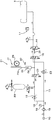
- a pneumatic circuit 1 according to a first embodiment of the present invention and a tire testing apparatus 2 provided with the pneumatic circuit 1 will be described with reference to FIGS. 1 and 2.
- the tire test apparatus 2 is for inspecting a product such as a uniformity for a tire T that has been finished, and is composed of a uniformity machine in the present embodiment.
- the tire test apparatus 2 includes a frame 3 provided in a tower shape on a floor surface, an upper tire shaft 4 and a lower tire shaft 5 attached to the frame 3, and Rims 6 and 7 fixed to the tire shafts 4 and 5, respectively, and a drum (not shown).
- the tire shafts 4 and 5 are arranged vertically so as to be rotatable around a common central axis extending in the vertical direction.
- the rims 6 and 7 are respectively provided at the lower end of the upper tire shaft 4 and the upper end of the lower tire shaft 5, and the tire T is fixed to the rims 6 and 7.
- the drum has an outer peripheral surface constituting a simulated road surface, and is driven to rotate about the central axis of the outer peripheral surface.
- the drum is arranged on the side of the tire T so that the outer peripheral surface of the drum, that is, the simulated road surface, contacts the tire T by moving horizontally.
- “upper and lower” means the upper and lower sides of the sheet of FIG.
- the air supply source 10 side is called “upstream side” of the pneumatic circuit 1
- the tire T side is called “downstream side”.
- upstream side and downstream side respectively correspond to the upstream side and the downstream side in the flow of compressed air (in the direction of the arrow in the figure) when compressed air is supplied into the tire T.
- the upper tire shaft 4 is provided on the upper side of the frame 3.
- the lower tire shaft 5 is disposed coaxially with the upper tire shaft 4 at a distance downward from the upper tire shaft 4 and is driven up and down. When these tire shafts 4 and 5 approach each other, the tire T is sandwiched and fixed between the upper and lower rims 6 and 7.
- the tire shaft or drum includes a load measuring device.
- This load measuring instrument measures the force generated in the tire T during the simulated traveling for measuring the uniformity of the tire T.
- the tire test apparatus 2 is provided with a pneumatic circuit 1 for adjusting the air pressure in the tire T by supplying compressed air into the tire T and discharging compressed air from the tire T.
- the pneumatic circuit 1 forms an air flow path from the air supply source 10 into the tire T as shown in FIG.
- the air flow path includes an air flow path 8 that is formed inside the upper tire shaft 4 and penetrates it vertically.
- the lower end of the air flow path 8 constitutes an air supply port 9, and the air flow path 8 communicates with the inside of the tire T through the air supply port 9.
- the pneumatic circuit 1 supplies and discharges compressed air to and from the tire T through the air flow path 8 and the air supply port 9. Specifically, this pneumatic circuit 1 adjusts the compressed air generated by the air supply source 10 to a predetermined air pressure and supplies it to the tire T, and has two systems of flow paths as shown in FIG. .
- One system is a bead seat system 11 for inflating the tire T in a short time and pressing the bead of the tire T against the rim, and the other system is a test system 12 used when testing the tire T.
- the compressed air flowing through the bead sheet system 11 is adjusted to an air pressure (bead sheet pressure) of about 0.4 MPa, and the compressed air flowing through the test system 12 is about 0.2 MPa lower than the bead sheet system 11 (the test air pressure). ) Is adjusted.
- the air flow path of the bead seat system 11 and the air flow path of the test system 12 are branched from each other on the way from the air supply source 10 to the tire T.
- the air adjusted to the respective air pressures in the respective flow paths again merges into one air flow path.
- test system 12 and the bead sheet system 11 will be described in detail.
- the path of the test system 12 includes a pressure regulating valve 13, a supply / discharge valve 14, a switching valve 15, a cutoff valve 16, and a pressure detection unit 17 in order from the air supply source 10 toward the downstream side.
- the path of the bead seat system 11 branches from the air flow path of the test system 12 on the downstream side of the air supply source 10, and merges with the path of the test system 12 by the switching valve 15.
- the pipe path of this bead seat system includes a bead pressure adjusting valve 22 for adjusting the pressure of the air that is provided and circulates to the bead pressure.
- the air supply source 10 is a factory air supply source including an air compressor (not shown), and generates compressed air having a pressure equal to or higher than the air pressure sufficient to inflate the tire T.
- the bead seat system 11 or the test system 12 is supplied to the tire T through the piping.
- An air filter 18 that collects dust in compressed air discharged from the air supply source 10 is provided between the air supply source 10 and the pipes of both the systems 11 and 12.
- a pressure gauge 19 for measuring the pressure of the compressed air generated by the air supply source 10 is provided.
- the pressure adjustment valve 13 of the test system 12 is provided downstream of the pressure gauge 19 and adjusts the pressure of the compressed air sent from the air supply source 10 to a predetermined pressure.
- the pressure regulating valve 13 is an internal pilot type pressure reducing valve having a relief function, and high-pressure (for example, 0.4 MPa) compressed air generated by the air supply source 10 is used as a test air pressure (for example, 0). The pressure is reduced to 2 MPa).
- the supply / exhaust valve 14 is a directional control valve provided on the downstream side of the pressure regulating valve 13, and an air supply position that allows air supply from the air supply source 10 to the tire T (a lower position in FIG. 2). And an exhaust position (upper position in FIG. 2) that allows exhaust from the tire T (release to the atmosphere).
- the supply / discharge valve 14 is a directional control valve in which pilot pressure is controlled by an electromagnetic method. When the supply / discharge valve 14 is operated in response to input of pilot pressure (on state), the supply / discharge valve 14 is in the supply position.
- a tank 23 (accumulator) capable of storing the compressed air in the pipe whose pressure is adjusted by the pressure adjusting valve 13 is provided between the pressure adjusting valve 13 and the supply / discharge valve 14.
- the switching valve 15 is provided on the downstream side of the supply / discharge valve 14, and an air flow path (pipe) of the test system 12 and an air flow path of the bead seat system 11 are routed from the supply / discharge valve 14 to the tire T. (Pipe) side, and thereby the air pressure in the tire T is switched between the test air pressure and a higher bead pressure.
- the switching valve 15 is a directional control valve in which the pilot pressure is controlled electromagnetically.
- the bead seat system 11 Forming a flow path for supplying the compressed air adjusted to the bead pressure by the bead pressure adjusting valve 22 into the tire T, and in a state in which the pilot pressure is not received and operated (off state), A flow path for supplying compressed air, which has been pressure-adjusted to the test air pressure by the pressure adjustment valve 13 of the test system 12, into the tire T is formed.
- the shutoff valve 16 is a directional control valve provided on the downstream side of the switching valve 15, and shuts off the flow path of the compressed air (upper position in FIG. 2) and the flow path. The position is switched to a cutoff position (lower position in FIG. 2) in which compressed air is contained in the air flow path between the cutoff valve 16 and the tire T.
- the shut-off valve 16 is a directional control valve in which the pilot pressure is controlled by an electromagnetic method. When the shut-off valve 16 is operated in response to the input of the pilot pressure (on state), the shut-off valve 16 is upstream. The flow of the compressed air between the side and the downstream side is blocked, and the free flow of the compressed air is allowed in the non-operating state (off state).
- the pressure detection unit 17 includes an air pressure sensor provided on the downstream side of the shutoff valve 16, and detects the air pressure in the tire T.
- this air pressure sensor is connected to the air flow path 8 formed inside the upper tire shaft 4 and can accurately detect the air pressure in the tire T attached to the rims 6 and 7. Thus, it is provided in the vicinity of the tire T.
- the pressure detection unit 17 outputs an electric signal corresponding to the air pressure toward the volume adjustment mechanism 21 as a control signal.
- the volume adjusting mechanism 21 increases or decreases the volume of the compressed air that acts on the tire T in accordance with the minute pressure fluctuation of the compressed air that acts on the tire T.
- the air pressure is finely adjusted based on the input detection signal.
- the bead pressure adjusting valve 22 is a pressure regulator having the same configuration as that of the pressure adjusting valve 13, but unlike the pressure adjusting valve 13, the pressure of the compressed air sent from the air supply source 10. Is adjusted to bead pressure higher than the test air pressure.
- the purpose of providing the volume adjusting mechanism 21 is as follows.
- the pressure adjusting valve 13 adjusts the air pressure acting in the tire T to the test air pressure, but actually the air pressure in the tire T changes minutely during the tire test regardless of the pressure adjustment. There is.
- Such a small change in air pressure is as small as 0.5 kPa to 1 kPa, and the pressure adjustment accuracy is only ⁇ 0.1% (for example, about 1 kPa in the case of a pressure regulator rated at 1.0 MPa). It is difficult to finely adjust the pressure with the non-pressure adjusting valve 13.
- the volume adjusting mechanism 21 makes it possible to finely adjust the air pressure in the tire T by increasing or decreasing the air volume between the tire T and the pressure adjusting valve 13 and the air volume inside the tire T. is there.
- the volume adjusting mechanism 21 is provided in a pipe (air flow path) of the test system 12 including the shutoff valve 16.
- the shutoff valve 16 is provided between the pressure regulating valve 13 and the tire T mounted between the pair of rims 6 and 7 of the tire testing device 2, and the volume regulating mechanism 21 is shut off. It is provided in a pipe (air flow path) further downstream of the valve 16.
- the volume adjusting mechanism 21 is a means for increasing or decreasing the volume of compressed air in the pipe and the tire T provided on the downstream side of the shutoff valve 16, that is, the volume of compressed air acting in the tire T.
- the air cylinder includes a cylinder 24, a piston 25 that moves in the cylinder 24, and a piston rod 25 a that is coupled to the piston 25.
- the cylinder 24 has a hollow cylindrical shape, and one end in the axial direction thereof communicates with a pipe (air flow path) between the shutoff valve 16 and the pressure detection unit 17, and the other end is opened to the outside via the silencer 20. ing.
- the piston 25 is inserted into the cylinder 24, hermetically partitions the internal space of the cylinder 24 into two chambers, and moves in the cylinder 24 to move the piping (on the downstream side of the shutoff valve 16) ( The volume of the chamber (the head side chamber in the example shown in FIG. 2) that communicates with the air flow path is increased or decreased, thereby making it possible to adjust the volume of the compressed air in the pipe.
- the piston rod 25 a extends from the piston 25 toward the side opposite to the pipe and is exposed to the outside of the cylinder 24.
- the power conversion mechanism 27 includes a rack and a pinion that mesh with each other, the rack is fixed to the piston rod along the piston rod, and the pinion is fixed to the output shaft of the servo motor 26. Therefore, the power conversion mechanism 27 moves the piston rod 25a and the piston 25 in the linear direction as the servo motor 26 rotates.
- the servo motor 26 functions as a drive unit for driving the piston 25 and the moving direction and moving speed (predetermined control operation) of the piston 25 according to the change in the air pressure in the tire T detected by the pressure detection unit 17. It has a function as a control unit that controls the amount of movement per hour).
- the control operation time is a predetermined unit time for controlling the volume adjusting mechanism 21 in accordance with a change in air pressure, and is a time required for operating the volume adjusting mechanism 21 once.
- the servo motor 26 determines the moving direction and moving speed of the piston 25 corresponding to the change amount of the air pressure and the increasing / decreasing direction thereof.
- the value obtained by converting the volume change of the air cylinder per control operation time into the pressure change of the compressed gas acting in the tire T is set to a value smaller than the pressure adjustment accuracy of the pressure adjustment valve 13.
- the control for determining the moving direction and moving speed of the piston 25 in accordance with the change of the air pressure in this way increases the accuracy of volume adjustment compared to simple control of the position of the piston 25 and torque control of the servo motor 26, for example.
- the air pressure in T can be adjusted with higher accuracy.
- the procedure of the tire test performed in the tire test apparatus 2 provided with such a pneumatic circuit 1 is as follows.
- the air pressure in the tire T is adjusted to the bead pressure by using the pipe of the bead seat system 11, whereby the tire T is expanded in a short time.
- the switching valve 15 is turned on and the shutoff valve 16 is turned off.
- the switching valve 15 in the on state shuts off the air flow path of the test system 12 from the shut-off valve 16 and connects the air flow path of the bead seat system 11 to the shut-off valve 16.
- the on-state shutoff valve 16 allows the flow of compressed air flowing from the bead seat system 11, thereby enabling the compressed air to be supplied to the tire T through a path on the bead seat system 11 side. To do.
- the pressure of the compressed air generated by the air supply source 10 is adjusted to the bead pressure by the bead pressure adjusting valve 22 provided in the middle of the path on the bead seat system 11 side.
- the compressed air adjusted to the bead pressure in this way is supplied to the tire T through the switching valve 15 and the shutoff valve 16, whereby the tire T is inflated in a short time, and an unillustrated bead of the tire T is provided.
- the part is firmly attached to the rims 6 and 7.
- the air pressure in the tire T is switched to a test air pressure lower than the bead pressure in preparation for a tire test.
- the switching valve 15 is switched from the on state to the off state while the supply / discharge valve 14 is in the on state and the shutoff valve 16 is in the off state, and the compressed air flow path is connected from the pipe of the bead seat system 11 to the test system.
- Switch to 12 pipes Specifically, the switching valve 15 shuts off the pipe of the bead seat system 11 from the tire T, connects the pipe of the test system 12 to the tire T, and connects the tire T to the tire T through the pipe of the test system 12. Allows supply of compressed air.
- the pressure adjusting valve 13 of the test system 12 adjusts the compressed air generated by the air supply source 10 to a test air pressure and releases the compressed air in the tire T that has been adjusted to the bead pressure to the outside. Reduce the pressure to the test air pressure. A part of the compressed air adjusted to the test air pressure by the pressure adjusting valve 13 is supplied to the tire T through the supply / discharge valve 14, the switching valve 15 and the shutoff valve 16, and the rest is stored in the tank 23. Is done. This compressed air adjusts the air pressure in the tire T to the test air pressure.
- the shutoff valve 16 When the air pressure in the tire T detected by the pressure detector 17 becomes the test air pressure, the shutoff valve 16 is activated and turned on, and the air flow path between the switching valve 15 and the tire T is shut off. To do. In other words, the shutoff valve 16 shuts off the air flow path (in the pipe) and the inside of the tire T downstream of the shutoff valve 16 from the circuit upstream of the shutoff valve 16 to form a closed space. Thereby, the preparation for performing the tire test is completed.
- the air pressure in the tire T may fluctuate slightly.
- Such fluctuation of the air pressure in the tire T includes both a decrease and an increase in the air pressure. Both the decrease and the increase are detected by the pressure detection unit 17 provided in the vicinity of the tire T, and the air pressure is adjusted. Output the corresponding detection signal.
- the volume adjustment mechanism 21 finely adjusts the air pressure acting on the tire based on the detection signal output from the pressure detection unit 17. Specifically, the servo motor 26 of the volume adjusting mechanism 21 drives the piston 25 of the air cylinder, thereby changing the volume of the cylinder chamber (head side chamber) on the side communicating with the air flow path in the closed space. The volume of compressed air in the closed space (in the pipe and in the tire T) is increased or decreased to correct the air pressure acting in the tire T to the test air pressure. For example, when the air pressure in the tire T detected by the pressure detector 17 fluctuates so as to be lower than the test air pressure, the piston 25 of the volume adjusting mechanism 21 tends to reduce the volume of the cylinder chamber on the side communicating with the pipe. Driven by.
- the volume of compressed air in the pipe and in the tire T is reduced, and the air pressure in the tire T can be raised correspondingly and returned to the test air pressure.
- the piston 25 is driven in the opposite direction, that is, in the direction of increasing the volume of the cylinder chamber on the side communicating with the pipe. The air pressure in the tire T is increased to the test air pressure.
- the switching valve 15 remains in the off state (while the piping of the test system 12 is used), and the shutoff valve 16 is switched to the off state.
- the flow of compressed air between the tire T and the supply / discharge valve 14 is allowed.
- the supply / discharge valve 14 is further switched to the OFF state, and the compressed air in the tire T and the volume adjusting mechanism 21 is exhausted outside the pipe through the silencer 28. That is, it opens to the atmosphere. Then, preparation for mounting the next tire T and return to the origin of the piston 25 of the volume adjusting mechanism 21 are performed.
- the supply / discharge valve 14 and the switching valve 15 that are in the off state can contribute to shortening the supply time of the compressed air when the tire test is continuously performed.
- the switching valve 15 blocks the upstream side pipe (the pipe of the bead seat system 11) from the downstream side pipe, so that the upstream side is not affected by the exhaust of compressed air in the tire T. Compressed air can be left in the piping.
- the supply / discharge valve 14 also shuts off the upstream piping (the piping of the test system 12) from the downstream piping, so that the upstream piping can be connected to the upstream piping regardless of the exhaust of compressed air in the tire T. Compressed air can be left.
- the time required to supply the compressed air when starting the next tire test is greatly shortened.
- the volume adjusting mechanism 21 increases or decreases the volume of the compressed air inside the pipe forming the air flow path between the tire T and the pressure adjusting valve 13 and inside the tire T as described above. Fine adjustment is ensured in response to minute fluctuations in air pressure, which is difficult to adjust with ordinary pressure regulators. As a result, the tire T can be maintained at the test air pressure with high accuracy during the tire test, and the uniformity can be accurately measured.
- the volume adjusting mechanism 21 can adjust the air pressure in the tire T at a low cost when it includes the above-described air cylinder as a specific means for increasing or decreasing the volume of the compressed air. In other words, the air pressure can be finely adjusted without increasing the price of the tire testing device 2.
- the shutoff valve 16 contributes to stabilization of the conditions of the tire test by shutting off the flow path downstream of the shutoff valve 16 and the pressure regulating valve 13.
- the pressure regulating valve 13 does not normally operate with a minute pressure fluctuation that occurs during a tire test. However, even if the pressure regulating valve 13 is unexpectedly activated due to some factor, the shutoff valve 16 does not flow downstream. By shutting off the road and the pressure regulating valve 13, the influence of the pressure regulating valve 13 is prevented from reaching the downstream side of the shutoff valve 16, thereby enabling the tire test to be performed under more stable test conditions. To.
- the pneumatic circuit 1 according to the second embodiment is different from the first embodiment as follows.
- the supply / discharge valve 14 has a flow path downstream of the switching valve 15, that is, an air flow between the switching valve 15 and the tire T mounted between the rims 6 and 7. It is provided on the road.
- the shutoff valve 16 according to the second embodiment is provided in a flow path upstream of the switching valve 15 and in the flow path of the test system 12, and is interposed between the switching valve 15 and the pressure regulating valve 13. is doing.
- the tank 23 and the volume adjusting mechanism 21 according to the second embodiment are connected to the flow path of the test system 12.
- the tank 23 is connected to the flow path of the test system 12 at a position between the shutoff valve 16 and the switching valve 15, and the volume adjusting mechanism 21 is positioned downstream of the tank 23, That is, it is connected to the flow path of the test system 12 at a position between the tank 23 and the switching valve 15.
- the volume adjusting mechanism 21 is configured to reduce the compressed air in the air flow path on the downstream side of the shutoff valve 16, the tire T, and the tank 23, in other words, the compressed air that exerts pressure on the tire T. Increase or decrease the volume.
- the cutoff valve 16 is provided between the pressure regulating valve 13 and the switching valve 15 in the air path of the test system 12, and between the cutoff valve 16 and the switching valve 15.
- the tank 23 is provided, and the volume adjusting mechanism 21 is adjacent to the downstream side of the tank 23.
- the shutoff valve 16 operates so as to shut off the downstream air path from the upstream side, so that not only the downstream air path (in the pipe) of the shutoff valve 16 and the tire T but also the inside of the tank 23. Block from the upstream flow path (that is, make it a closed space).
- the volume adjusting mechanism 21 adjusts the volume of compressed air at three locations in the pipe, the tire T, and the tank 23, in other words, the volume of the compressed air in the closed space.
- the shutoff valve 16 is driven after the air pressure in the tire T detected by the pressure detector 17 becomes the test air pressure.
- the air flow path on the downstream side of 16, the inside of the tank 23 and the inside of the tire T are blocked from the flow path on the upstream side of the cutoff valve 16.
- the volume adjusting mechanism 21 includes not only the air flow path on the downstream side of the shutoff valve 16 and the compressed air existing in the tire T but also the compressed air in the tank 23. Adjust the volume of air.
- the tank 23 stores the compressed air in the air flow path whose pressure has been adjusted by the pressure regulating valve 13, the volume of the compressed air to be adjusted increases by the volume of the tank 23. Therefore, even if the air pressure in the tire T fluctuates, the amount of fluctuation is relatively small with respect to the total amount of compressed air in the closed space, and therefore hardly affects the measurement accuracy of uniformity. Further, since it is not necessary to use a volume adjustment mechanism 21 that can adjust the volume adjustment amount with high accuracy, a general air cylinder or the like can be used for the volume adjustment mechanism 21, and the manufacturing cost of the tire testing apparatus 2 can be increased. Can be kept low.
- a tank 23 and a volume adjusting mechanism 21 are provided between the pressure regulating valve 13 and the supply / discharge valve 14 as in the second embodiment. Unlike the form, the shutoff valve 16 is not provided.
- a supply / discharge valve 29 is provided between the tank 23 and the volume adjusting mechanism 21.
- the supply / discharge valve 29 functions as the supply / discharge valve 14 provided in the test system 12 of FIG. 2 (exhaust when reducing the bead seat pressure to the test air pressure and exhaust when releasing the tire internal pressure after the test is completed). It is used for exhaust when reducing the bead seat pressure to the test air pressure.
- the present invention is established depending on the characteristics of the pressure regulating valve 13. Specifically, when a pressure regulator having only a pressure adjustment accuracy that does not operate with a slight pressure fluctuation generated during a tire test is used as the pressure adjustment valve 13, the pressure adjustment valve 13 is a shut-off valve.
- the compressed air that functions in place of 16 and that acts downstream of the pressure regulating valve 13 (in the pipe), in the tire T and in the tank 23, in other words, in the tire T, is substantially applied. It can be contained. Therefore, in this case, as shown in FIG. 4, even if the shutoff valve 16 is not provided, the volume adjusting mechanism 21 is compressed air that is substantially confined on the downstream side of the pressure adjusting valve 13 (compressed air that exerts pressure on the tire T). ) Can be accurately adjusted.
- the volume adjustment mechanism of the first to third embodiments controls the moving direction and moving speed of the piston 25 based on the air pressure detected by the pressure detector 17.
- a volume adjusting mechanism 21 that controls only the moving direction of the piston 25 is provided.
- the volume to be changed in the control operation time (volume change per control operation time of the volume adjusting mechanism 21) is converted into a fluctuation value of the air pressure acting in the tire T. This is set to a constant value smaller than the pressure adjustment accuracy of the pressure adjustment valve 13 for adjusting the inside of the tire T to the test air pressure.
- the volume adjusting mechanism 21 determines only the moving direction of the piston 25 based on the detected air pressure change amount and the increasing / decreasing direction based on the air pressure detected by the pressure detecting unit 17.
- the volume adjusting mechanism 21 configured in this way increases the air pressure acting in the tire T, in other words, the piston 25 in the forward direction.
- the piston 25 is moved in the forward direction and the reverse direction. If the inside of the tire T does not become the test air pressure even when the piston 25 is moved, the piston 25 may be moved repeatedly. In this way, the air pressure in the tire T can be adjusted with high accuracy that cannot be adjusted by the pressure adjustment valve 13.
- the time required for control is short. Therefore, it is effective when the control operation time of the volume adjusting mechanism 21 is desired to be extremely short.
- the present invention is not limited to the above-described embodiments, and the shape, structure, material, combination, and the like of each member can be appropriately changed without changing the essence of the invention.
- the tire testing apparatus according to the present invention is not limited to the uniformity machine as described above.
- the pneumatic circuit according to the present invention can also be applied to a tire testing machine that performs evaluations other than uniformity.
- the switching valve 15 switches the compressed air supply path between the path including the pressure adjusting valve 13 and the path including the beat pressure adjusting valve 22 to switch the air pressure of the tire T.
- the pressure adjusting valve 13 may be a pilot switching valve or an electromagnetic switching valve, and the air pressure of the tire T can be switched with a plurality of different pressures only by the operation of the pressure adjusting valve 13.
- a pressure reducing valve 13 is used as the pressure adjusting valve 13 for adjusting the secondary pressure to a predetermined value, but a sequence valve or the like can also be used as the pressure adjusting valve 13, for example.
- the power conversion mechanism 27 for converting the rotational driving force of the servo motor 26 into the linear motion of the piston 25 is configured by a rack and a pinion.
- a feed screw may be used.
- a linear motor may be used as a power source for driving the piston 25.
- the volume adjusting mechanism 21 controls the moving direction and moving speed of the piston 25 based on the air pressure detected by the pressure detecting unit 17, but the volume adjusting mechanism according to the present invention is
- the torque of the servo motor 26 or the position of the piston 25 may be controlled in accordance with a change in air pressure detected by the pressure detector 17.
- the present invention provides a pneumatic circuit for a tire testing apparatus that can reliably adjust minute fluctuations in air pressure occurring during a tire test in a short time.
- the present invention also provides a tire testing apparatus and a tire testing method that can accurately inspect a tire at low cost by using the pneumatic circuit.
- a pneumatic circuit provided by the present invention is provided, for example, in a tire testing apparatus having a tire holding portion that includes a pair of rims and holds a tire, and is compressed air with respect to the tire held by the tire holding portion.
- An air supply source for supplying pressure
- a pressure adjusting valve for adjusting the pressure of compressed air supplied from the air supply source to the tire to a test air pressure
- a pressure detection unit for detecting air pressure acting in the tire
- a volume adjusting mechanism connected to an air flow path between the tire and the pressure adjusting valve. This volume adjustment mechanism increases or decreases the volume of compressed air that applies pressure to the tire whose pressure has been adjusted by the pressure adjustment valve in accordance with the change in the air pressure.
- the present invention further includes, for example, a supply / discharge valve that is provided on the downstream side of the pressure regulating valve and supplies compressed air to the tire and exhausts compressed air from the tire, and the pressure detection unit Provided on the downstream side of the supply / discharge valve, the volume adjustment mechanism may increase or decrease the volume of the compressed air in the tire and the air flow path between the tire and the pressure adjustment valve.
- the present invention has been made paying attention to the relationship between the pressure and volume of the compressed air. Specifically, in a constant mass of compressed air, assuming that the temperature is constant, the product of pressure and volume is kept constant according to Boyle's law.
- the pressure fluctuation during the tire test described above is generally less than 0.5 kPa, and even if the pressure fluctuation is replaced with the volume fluctuation, the volume adjustment amount is not large. For example, when 0.2 liters of compressed air of 0.2 MPa is contained in a tire or an air flow path and there is a pressure fluctuation of 0.5 kPa, 0.125 liter (125 cm 3 ) is obtained by correcting this pressure fluctuation to a volume fluctuation. It will be about.
- the present inventor has provided a volume adjustment mechanism for increasing or decreasing the volume of compressed air in the pipe connecting the tire and the pressure adjustment valve, and for reducing a slight fluctuation in the air pressure in the tire for a short time.
- the present invention has been completed by convincingly adjusting it.
- This volume adjustment mechanism can be specifically used in the following pneumatic circuit.
- the volume adjusting mechanism includes: It is preferable to connect to the air flow path on the downstream side of the shut-off valve and increase or decrease the volume of the compressed air in the tire and the air flow path arranged on the downstream side of the shut-off valve.
- the volume adjusting mechanism It is only necessary to adjust the volume of the compressed air in the downstream air flow path and the tire, in other words, the pressure applied to the tire. That is, since the volume of the air to be adjusted by the volume adjustment mechanism is small, the air pressure in the tire can be adjusted with higher responsiveness and accuracy.
- the shut-off valve enables more stable measurement of the tire.
- the pressure regulating valve usually does not operate at a minute pressure fluctuation level that occurs during a tire test, but the pressure regulating valve operates for some unexpected reason.
- the air pressure in the tire is not constant and may vary.
- the shut-off valve prevents the malfunction of the pressure control valve from affecting the air pressure downstream of the shut-off valve by shutting off the flow of compressed air from the pressure control valve to the tire. This allows more stable measurement of tire uniformity, for example.
- a shut-off valve provided between the pressure regulating valve and the tire mounted and capable of shutting off a flow of compressed air from the pressure regulating valve toward the tire, and provided on the downstream side of the shut-off valve and the pressure
- the volume adjusting mechanism is connected to an air flow path on the downstream side of the shutoff valve in the same manner as the tank. The operation may be performed so as to increase or decrease the volume of the compressed air that applies pressure to the air flow path, the tire, and the tank.
- the tank capable of storing the compressed air in the air flow passage whose pressure has been adjusted by the pressure regulating valve increases the air volume in the pneumatic circuit and functions as a buffer so that the tire test can be performed. Reduce the fluctuation range of the air pressure inside the tire. As a result, the change in the air pressure in the tire becomes small, and the measurement accuracy of the tire test such as uniformity is hardly affected. Even if the air pressure fluctuates regardless of the increase of the air volume in the air pressure circuit by such a tank, the volume adjustment mechanism can suppress the fluctuation of the air pressure and can measure the uniformity of the tire, for example, with high accuracy. To. In this case, since the volume adjusting mechanism is not required to adjust the volume with high accuracy, it can be constituted by a general air cylinder. This makes it possible to keep the manufacturing cost of the tire testing device low.
- the volume adjustment mechanism May operate so as to increase or decrease the volume of compressed air that exerts pressure on the air flow path downstream from the pressure regulating valve, the tire, and the tank.
- the volume adjusting mechanism includes a cylinder communicating with the air flow path and an air cylinder including a piston moving in the cylinder, and compression in the air flow path by moving the piston in the cylinder. What has the drive part which adjusts the volume of air is suitable. The use of such a volume adjusting mechanism using an air cylinder makes it possible to accurately adjust the air pressure in the tire at a low cost.
- the volume adjusting mechanism including the air cylinder and the driving unit further includes a control unit that controls driving of the piston by the driving unit.
- a control unit that controls driving of the piston by the driving unit.
- a unit that controls the driving direction and speed of the piston by the driving unit according to a change in air pressure detected by the pressure detection unit, and a unit that controls the driving direction and torque of the piston are suitable. It is.
- the drive unit and the control unit can be configured by, for example, a servo motor.
- the present invention also includes a tire holding portion for holding a tire and a pneumatic circuit for supplying air pressure to the tire held by the tire holding portion, and the pneumatic circuit is formed by any one of the pneumatic circuits described above.
- a tire testing apparatus constructed. In this tire test apparatus, for example, the uniformity of the tire is accurately measured by adjusting a minute fluctuation of the air pressure in the tire generated during the tire test in a short time.
- the present invention also provides a tire test method for testing a tire held in a tire holding portion.
- the tire test method provided by the present invention includes a test of the tire while adjusting the pressure of the compressed air to a predetermined test air pressure by a pressure regulating valve and applying the pressure to the inside of the tire, and the pressure Compressed air that exerts pressure on the tire pressure-adjusted by the pressure regulating valve according to the air pressure fluctuation so as to compensate for the minute fluctuation of the air pressure inside the tire that occurs regardless of adjustment of the regulating valve.
- the test of the tire is performed in a state where compressed air whose pressure is adjusted by a pressure adjusting valve is supplied to or exhausted from the tire and the inside of the tire is maintained at a predetermined test air pressure.
- the air pressure in the tire fluctuates during the test, the volume of compressed air in the air flow path between the tire held in the tire holding portion and the pressure regulating valve and in the tire is increased or decreased. By doing so, the air pressure in the tire may be adjusted to the test air pressure.
- the air pressure By increasing or decreasing the volume of the compressed air, it is possible to adjust the air pressure to the test air pressure in a short time even for minute fluctuations in air pressure that cannot be adjusted by the pressure adjustment valve. For example, the tire uniformity can be accurately adjusted. It can be measured.
Landscapes
- Physics & Mathematics (AREA)
- General Physics & Mathematics (AREA)
- Tires In General (AREA)
- Vehicle Cleaning, Maintenance, Repair, Refitting, And Outriggers (AREA)
- Testing Of Balance (AREA)
Abstract
Description
Claims (12)
- タイヤを保持するタイヤ保持部を有するタイヤ試験装置に設けられる空気圧回路であって、
前記タイヤ保持部に保持されるタイヤに対して圧縮空気を供給する空気供給源と、
この空気供給源から前記タイヤに供給される圧縮空気の圧力を試験用空気圧に調整する圧力調整弁と、
前記圧縮空気の供給により前記タイヤ内に作用する空気圧を検知する圧力検知部と、
前記タイヤ内と前記圧力調整弁との間の空気流路に接続される体積調整機構とを備え、この体積調整機構は、前記空気圧の変動に応じて、当該圧力調整弁で圧力調整された当該タイヤ内に圧力を作用させる圧縮空気の体積を増減させる、タイヤ試験装置の空気圧回路。 - 請求項1記載のタイヤ試験装置の空気圧回路であって、
前記圧力調整弁の下流側に設けられて前記タイヤへの圧縮空気の給気および当該タイヤからの圧縮空気の排気をする給排弁をさらに備え、
前記圧力検知部は、前記給排弁の下流側に設けられ、
前記体積調整機構は、前記タイヤと前記圧力調整弁との間の空気流路及びタイヤ内の圧縮空気の体積を増減させる、タイヤ試験装置の空気圧回路。 - 請求項1または2に記載のタイヤ試験装置の空気圧回路であって、
前記圧力調整弁と前記タイヤとの間に設けられて前記圧力調整弁からタイヤに向かう圧縮空気の流通を遮断可能な遮断弁をさらに備え、
前記体積調整機構は、前記遮断弁の下流側の空気流路に接続されて、該遮断弁の下流側に配備された空気流路及びタイヤ内の圧縮空気の体積を増減させるように作動する、タイヤ試験装置の空気圧回路。 - 請求項1または2に記載のタイヤ試験装置の空気圧回路であって、
前記圧力調整弁と装着されたタイヤとの間に設けられ、前記圧力調整弁からタイヤに向かう圧縮空気の流通を遮断可能な遮断弁と、
当該遮断弁より下流側に設けられて前記圧力調整弁で圧力調整された空気流路の圧縮空気を貯留可能なタンクとをさらに備え、
前記体積調整機構は、前記タンクと同じく前記遮断弁の下流側の空気流路に接続されて、当該空気流路と、前記タイヤ内と、前記タンク内とに圧力を作用させる圧縮空気の体積を増減させるように作動する、タイヤ試験装置の空気圧回路。 - 請求項2記載のタイヤ試験装置の空気圧回路であって、
前記給排弁と前記圧力調整弁との間に設けられて当該圧力調整弁で圧力調整された前記圧縮空気を貯留可能なタンクをさらに備え、
前記体積調整機構は、前記圧力調整弁より下流側の空気流路と、前記タイヤ内と、前記タンク内に圧力を作用させる圧縮空気の体積を増減させるように作動する、タイヤ試験装置の空気圧回路。 - 請求項1または2記載のタイヤ試験装置の空気圧回路であって、
前記体積調整機構は、前記空気流路に連通するシリンダおよびこのシリンダ内を移動するピストンを含むエアシリンダと、前記ピストンを前記シリンダ内で移動させることにより前記空気流路内の圧縮空気の体積を調整する駆動部とを有する、タイヤ試験装置の空気圧回路。 - 請求項6に記載のタイヤ試験装置の空気圧回路であって、
前記体積調整機構は、前記圧力検知部で検知された空気圧の変化に応じて前記駆動部による前記ピストンの駆動を制御する制御部をさらに有する、タイヤ試験装置の空気圧回路。 - 請求項7に記載のタイヤ試験装置の空気圧回路であって、
前記体積調整機構は、前記圧力検知部で検知された空気圧の変化に応じて前記駆動部による前記ピストンの駆動方向及び速度を制御する、タイヤ試験装置の空気圧回路。 - 請求項7に記載のタイヤ試験装置の空気圧回路であって、
前記体積調整機構は、前記圧力検知部で検知された空気圧の変化に応じて前記駆動部による前記ピストンの駆動方向及びトルクを制御する、タイヤ試験装置の空気圧回路。 - タイヤを保持するタイヤ保持部と、このタイヤ保持部に保持されたタイヤに対して空気圧を供給するための空気圧回路とを備えたタイヤ試験装置であって、前記空気圧回路が請求項1または2記載の空気圧回路からなる、タイヤ試験装置。
- タイヤ保持部に保持されたタイヤの試験を行うためのタイヤ試験方法であって、
圧縮空気の圧力を圧力調整弁により所定の試験用空気圧に調整して当該圧力をタイヤの内部に作用させながら当該タイヤの試験を行うことと、
前記圧力調整弁の調整にかかわらず生じる前記タイヤ内の空気圧の微小な変動を補償するように、当該空気圧の変動に応じて、当該圧力調整弁で圧力調整された当該タイヤ内に圧力を作用させる圧縮空気の体積を増減させることとを含む、タイヤ試験方法。 - 請求項11記載のタイヤ試験方法であって、
前記タイヤの試験は、前記圧力調整弁により圧力を調整した圧縮空気を前記タイヤに対して給気又は排気して当該タイヤ内を所定の試験用空気圧に維持した状態で行われ、
前記試験中にタイヤ内の空気圧が変動した際に、前記タイヤ保持部に保持されたタイヤと前記圧力調整弁との間の空気流路の内部及び前記タイヤの内部の圧縮空気の体積を増減させることにより前記タイヤ内の空気圧が前記試験用空気圧に調整される、タイヤ試験方法。
Priority Applications (3)
| Application Number | Priority Date | Filing Date | Title |
|---|---|---|---|
| RU2012101354/11A RU2483286C1 (ru) | 2009-06-17 | 2010-06-17 | Пневматический контур для устройства тестирования шин, устройство тестирования шин и способ тестирования шины |
| US13/375,304 US8511157B2 (en) | 2009-06-17 | 2010-06-17 | Pneumatic circuit for tire testing device, tire testing device, and tire testing method |
| CN201080026953.5A CN102803920B (zh) | 2009-06-17 | 2010-06-17 | 轮胎试验装置的气压回路、轮胎试验装置及轮胎试验方法 |
Applications Claiming Priority (2)
| Application Number | Priority Date | Filing Date | Title |
|---|---|---|---|
| JP2009-144304 | 2009-06-17 | ||
| JP2009144304A JP4979740B2 (ja) | 2009-06-17 | 2009-06-17 | タイヤ試験装置の空気圧回路、タイヤ試験装置及びタイヤ試験方法 |
Publications (1)
| Publication Number | Publication Date |
|---|---|
| WO2010146859A1 true WO2010146859A1 (ja) | 2010-12-23 |
Family
ID=43356189
Family Applications (1)
| Application Number | Title | Priority Date | Filing Date |
|---|---|---|---|
| PCT/JP2010/004027 Ceased WO2010146859A1 (ja) | 2009-06-17 | 2010-06-17 | タイヤ試験装置の空気圧回路、タイヤ試験装置及びタイヤ試験方法 |
Country Status (5)
| Country | Link |
|---|---|
| US (1) | US8511157B2 (ja) |
| JP (1) | JP4979740B2 (ja) |
| CN (1) | CN102803920B (ja) |
| RU (1) | RU2483286C1 (ja) |
| WO (1) | WO2010146859A1 (ja) |
Families Citing this family (17)
| Publication number | Priority date | Publication date | Assignee | Title |
|---|---|---|---|---|
| IT1401825B1 (it) * | 2010-09-27 | 2013-08-28 | Magneti Marelli Spa | Metodo di controllo della velocita' di un motore a combustione interna sovralimentato mediante un turbocompressore |
| WO2012176359A1 (ja) * | 2011-06-23 | 2012-12-27 | 株式会社ブリヂストン | タイヤ試験装置 |
| JP5631290B2 (ja) * | 2011-10-06 | 2014-11-26 | 株式会社神戸製鋼所 | タイヤユニフォミティ試験装置及びタイヤユニフォミティ試験方法 |
| JP5631289B2 (ja) * | 2011-10-06 | 2014-11-26 | 株式会社神戸製鋼所 | タイヤユニフォミティ試験装置及びタイヤユニフォミティ試験方法 |
| CN103842792B (zh) * | 2011-10-06 | 2016-06-29 | 株式会社神户制钢所 | 轮胎均匀度试验装置及轮胎均匀度试验方法 |
| JP5642040B2 (ja) * | 2011-10-06 | 2014-12-17 | 株式会社神戸製鋼所 | タイヤユニフォミティ試験装置及びタイヤユニフォミティ試験方法 |
| KR101496513B1 (ko) * | 2012-06-04 | 2015-02-26 | 주식회사 엘지화학 | 에어셀의 피로수명 평가 방법 및 이에 사용되는 평가 장치 |
| JP6022987B2 (ja) * | 2013-04-03 | 2016-11-09 | 株式会社神戸製鋼所 | タイヤ試験装置の空気圧回路 |
| EP3028029B1 (en) * | 2013-08-01 | 2020-05-27 | MTS Systems Corporation | Tire testing apparatus |
| JP6057942B2 (ja) | 2014-04-22 | 2017-01-11 | 三菱重工マシナリーテクノロジー株式会社 | タイヤ保持装置、該タイヤ保持装置を備えるタイヤ試験システム |
| JP6692181B2 (ja) * | 2016-02-29 | 2020-05-13 | 国際計測器株式会社 | 動釣合い試験装置 |
| CN107444671A (zh) * | 2017-08-01 | 2017-12-08 | 中国人民解放军海军航空工程学院青岛校区 | 飞机轮胎自动充气装置 |
| KR102346799B1 (ko) * | 2020-06-11 | 2022-01-04 | 넥센타이어 주식회사 | 타이어 패턴 블록 강성 측정 장치 |
| IT202100005957A1 (it) * | 2021-03-12 | 2022-09-12 | Nexion Spa | Dispositivo di gonfiaggio di uno pneumatico e metodo per il controllo di un processo di gonfiaggio di uno pneumatico |
| JP2022142040A (ja) * | 2021-03-16 | 2022-09-30 | トヨタ自動車株式会社 | 工場エアシステム |
| CN115165402B (zh) * | 2022-06-02 | 2024-07-05 | 智己汽车科技有限公司 | 一种车辆轮胎的驾驶性能测试装置 |
| CN118408760B (zh) * | 2024-07-03 | 2024-09-03 | 威海市润通橡胶有限公司 | 一种新能源汽车轮胎内胎用检测台 |
Citations (3)
| Publication number | Priority date | Publication date | Assignee | Title |
|---|---|---|---|---|
| US4491013A (en) * | 1983-04-15 | 1985-01-01 | Bubik Leslie M | Apparatus and method for high pressure testing and inspection of tires |
| JPH0560640A (ja) * | 1991-09-05 | 1993-03-12 | Kobe Steel Ltd | タイヤのインフレーシヨン装置及びインフレーシヨン方法 |
| JP5070095B2 (ja) * | 2008-03-19 | 2012-11-07 | 三洋電機株式会社 | 投写型映像表示装置及びこれを用いた投写型映像表示システム |
Family Cites Families (18)
| Publication number | Priority date | Publication date | Assignee | Title |
|---|---|---|---|---|
| JPS57141534A (en) * | 1981-02-26 | 1982-09-01 | Kobe Steel Ltd | Compensating method for measuring error of tire uniformity machine |
| US4702287A (en) | 1986-08-22 | 1987-10-27 | Eagle-Picher Industries, Inc. | Method and apparatus for controlling the automatic inflation of tires for testing |
| DE3825505C2 (de) * | 1988-07-27 | 1994-12-22 | Hofmann Gmbh & Co Kg Maschinen | Vorrichtung zur Überwachung und Steuerung eines Reifenfülldruckes bei einer Reifenprüfmaschine |
| JPH0570095A (ja) | 1991-09-10 | 1993-03-23 | Hitachi Kiden Kogyo Ltd | 下降障害物検出装置 |
| US5587698A (en) * | 1992-02-05 | 1996-12-24 | Genna; Robert A. | Automatic tire pressure control system for a vehicle |
| US5291776A (en) * | 1992-04-13 | 1994-03-08 | Akron Special Machinery | Tire inflation regulator for tire uniformity machine |
| JPH0695057A (ja) | 1992-06-25 | 1994-04-08 | Fujitsu Kiden Ltd | 投影型液晶表示装置の表題表示方式 |
| IT1314448B1 (it) * | 2000-10-30 | 2002-12-13 | Butler Eng & Marketing | Impianto per il gonfiaggio rapido di pneumatici. |
| FR2822413B1 (fr) * | 2001-03-20 | 2004-07-09 | Syegon | Systeme de regulation de la pression de gonflage d'un pneumatique |
| US6758088B2 (en) * | 2002-04-22 | 2004-07-06 | Dana Corporation | Active adaptation of control algorithms for a central tire inflation system |
| JP4103952B2 (ja) * | 2002-05-10 | 2008-06-18 | 横浜ゴム株式会社 | タイヤ加硫成形後における後加硫・タイヤ仕上げ・測定方法及びその装置 |
| KR20040026428A (ko) * | 2002-09-24 | 2004-03-31 | 한국타이어 주식회사 | 완성 타이어의 균일성 검사장치 |
| ITVR20040009A1 (it) * | 2004-01-23 | 2004-04-23 | Butler Eng & Marketing | Dispositivo di gonfiaggio rapido di un pneumatico senza camera d'aria |
| CN100480071C (zh) * | 2004-04-23 | 2009-04-22 | 倍耐力轮胎股份公司 | 具有受控气压和蓄压器的车轮 |
| DE102004029736A1 (de) * | 2004-06-19 | 2006-01-19 | Deere & Company, Moline | Reifendruckeinstellanlage |
| FR2881080B1 (fr) * | 2005-01-27 | 2007-04-13 | Michelin Soc Tech | Dispositif et procede de mesure et de regularisation de la pression d'un pneumatique |
| CA2524612A1 (en) * | 2005-02-16 | 2006-08-16 | Jaewon Jwc Cho | Tire wheel capable of two phases of pressure adjustment |
| CN101071087B (zh) * | 2007-04-29 | 2011-09-07 | 茹长渠 | 汽车轮胎预警系统 |
-
2009
- 2009-06-17 JP JP2009144304A patent/JP4979740B2/ja not_active Expired - Fee Related
-
2010
- 2010-06-17 WO PCT/JP2010/004027 patent/WO2010146859A1/ja not_active Ceased
- 2010-06-17 RU RU2012101354/11A patent/RU2483286C1/ru active
- 2010-06-17 CN CN201080026953.5A patent/CN102803920B/zh not_active Expired - Fee Related
- 2010-06-17 US US13/375,304 patent/US8511157B2/en not_active Expired - Fee Related
Patent Citations (3)
| Publication number | Priority date | Publication date | Assignee | Title |
|---|---|---|---|---|
| US4491013A (en) * | 1983-04-15 | 1985-01-01 | Bubik Leslie M | Apparatus and method for high pressure testing and inspection of tires |
| JPH0560640A (ja) * | 1991-09-05 | 1993-03-12 | Kobe Steel Ltd | タイヤのインフレーシヨン装置及びインフレーシヨン方法 |
| JP5070095B2 (ja) * | 2008-03-19 | 2012-11-07 | 三洋電機株式会社 | 投写型映像表示装置及びこれを用いた投写型映像表示システム |
Also Published As
| Publication number | Publication date |
|---|---|
| US8511157B2 (en) | 2013-08-20 |
| US20120085158A1 (en) | 2012-04-12 |
| CN102803920B (zh) | 2015-06-17 |
| JP4979740B2 (ja) | 2012-07-18 |
| JP2011002296A (ja) | 2011-01-06 |
| RU2483286C1 (ru) | 2013-05-27 |
| CN102803920A (zh) | 2012-11-28 |
Similar Documents
| Publication | Publication Date | Title |
|---|---|---|
| JP4979740B2 (ja) | タイヤ試験装置の空気圧回路、タイヤ試験装置及びタイヤ試験方法 | |
| JP6022987B2 (ja) | タイヤ試験装置の空気圧回路 | |
| JP6657520B2 (ja) | タイヤ試験装置のタイヤ空気充填機構及びタイヤ空気充填方法 | |
| CN103842792B (zh) | 轮胎均匀度试验装置及轮胎均匀度试验方法 | |
| US9457694B2 (en) | Device and method for operating a plurality of fillable containers, in particular inflatable air cushions in a motor vehicle seat | |
| CN101749304A (zh) | 用于控制过程介质流的阀装置的磨损状态的诊断方法 | |
| CN106197902A (zh) | 一种气密检测装置及其伺服控制方法 | |
| JP5059075B2 (ja) | タイヤ試験装置の空気圧回路、タイヤ試験装置及びタイヤ試験方法 | |
| CN111358223B (zh) | 气囊自检系统及方法 | |
| JP4923957B2 (ja) | リーク検査装置 | |
| JP5642040B2 (ja) | タイヤユニフォミティ試験装置及びタイヤユニフォミティ試験方法 | |
| CN112284715A (zh) | 一种车用高压氢气减压阀测试装置 | |
| JP5014409B2 (ja) | タイヤ試験装置の空気圧回路、タイヤ試験装置及びタイヤ試験方法 | |
| JP3580786B2 (ja) | 圧力校正装置 | |
| JP5455533B2 (ja) | 圧力制御装置 | |
| JP7856486B2 (ja) | 油圧システムにおけるキャリブレーションシステム | |
| JP2010276497A (ja) | 車両輪荷重調整装置 | |
| JP5631290B2 (ja) | タイヤユニフォミティ試験装置及びタイヤユニフォミティ試験方法 | |
| JP4863453B2 (ja) | 突出部付きキャップの検査方法及びその装置 | |
| WO2012049130A1 (en) | Methods of and apparatuses for balancing electrode arms of a welding device taking into account spatial orientation | |
| CN121720664A (zh) | 一种用于压缩机流量计开关的质量检测装置及方法 |
Legal Events
| Date | Code | Title | Description |
|---|---|---|---|
| WWE | Wipo information: entry into national phase |
Ref document number: 201080026953.5 Country of ref document: CN |
|
| 121 | Ep: the epo has been informed by wipo that ep was designated in this application |
Ref document number: 10789238 Country of ref document: EP Kind code of ref document: A1 |
|
| WWE | Wipo information: entry into national phase |
Ref document number: 13375304 Country of ref document: US |
|
| WWE | Wipo information: entry into national phase |
Ref document number: 9476/CHENP/2011 Country of ref document: IN |
|
| NENP | Non-entry into the national phase |
Ref country code: DE |
|
| WWE | Wipo information: entry into national phase |
Ref document number: 2012101354 Country of ref document: RU |
|
| 122 | Ep: pct application non-entry in european phase |
Ref document number: 10789238 Country of ref document: EP Kind code of ref document: A1 |