WO2010146681A1 - 電池システム及び電池システム搭載車両 - Google Patents
電池システム及び電池システム搭載車両 Download PDFInfo
- Publication number
- WO2010146681A1 WO2010146681A1 PCT/JP2009/061086 JP2009061086W WO2010146681A1 WO 2010146681 A1 WO2010146681 A1 WO 2010146681A1 JP 2009061086 W JP2009061086 W JP 2009061086W WO 2010146681 A1 WO2010146681 A1 WO 2010146681A1
- Authority
- WO
- WIPO (PCT)
- Prior art keywords
- upper limit
- battery
- secondary battery
- battery system
- electric quantity
- Prior art date
- Legal status (The legal status is an assumption and is not a legal conclusion. Google has not performed a legal analysis and makes no representation as to the accuracy of the status listed.)
- Ceased
Links
Images



Classifications
-
- H—ELECTRICITY
- H01—ELECTRIC ELEMENTS
- H01M—PROCESSES OR MEANS, e.g. BATTERIES, FOR THE DIRECT CONVERSION OF CHEMICAL ENERGY INTO ELECTRICAL ENERGY
- H01M10/00—Secondary cells; Manufacture thereof
- H01M10/42—Methods or arrangements for servicing or maintenance of secondary cells or secondary half-cells
- H01M10/44—Methods for charging or discharging
-
- B—PERFORMING OPERATIONS; TRANSPORTING
- B60—VEHICLES IN GENERAL
- B60L—PROPULSION OF ELECTRICALLY-PROPELLED VEHICLES; SUPPLYING ELECTRIC POWER FOR AUXILIARY EQUIPMENT OF ELECTRICALLY-PROPELLED VEHICLES; ELECTRODYNAMIC BRAKE SYSTEMS FOR VEHICLES IN GENERAL; MAGNETIC SUSPENSION OR LEVITATION FOR VEHICLES; MONITORING OPERATING VARIABLES OF ELECTRICALLY-PROPELLED VEHICLES; ELECTRIC SAFETY DEVICES FOR ELECTRICALLY-PROPELLED VEHICLES
- B60L3/00—Electric devices on electrically-propelled vehicles for safety purposes; Monitoring operating variables, e.g. speed, deceleration or energy consumption
- B60L3/0023—Detecting, eliminating, remedying or compensating for drive train abnormalities, e.g. failures within the drive train
- B60L3/0046—Detecting, eliminating, remedying or compensating for drive train abnormalities, e.g. failures within the drive train relating to electric energy storage systems, e.g. batteries or capacitors
-
- B—PERFORMING OPERATIONS; TRANSPORTING
- B60—VEHICLES IN GENERAL
- B60L—PROPULSION OF ELECTRICALLY-PROPELLED VEHICLES; SUPPLYING ELECTRIC POWER FOR AUXILIARY EQUIPMENT OF ELECTRICALLY-PROPELLED VEHICLES; ELECTRODYNAMIC BRAKE SYSTEMS FOR VEHICLES IN GENERAL; MAGNETIC SUSPENSION OR LEVITATION FOR VEHICLES; MONITORING OPERATING VARIABLES OF ELECTRICALLY-PROPELLED VEHICLES; ELECTRIC SAFETY DEVICES FOR ELECTRICALLY-PROPELLED VEHICLES
- B60L53/00—Methods of charging batteries, specially adapted for electric vehicles; Charging stations or on-board charging equipment therefor; Exchange of energy storage elements in electric vehicles
- B60L53/10—Methods of charging batteries, specially adapted for electric vehicles; Charging stations or on-board charging equipment therefor; Exchange of energy storage elements in electric vehicles characterised by the energy transfer between the charging station and the vehicle
- B60L53/14—Conductive energy transfer
-
- B—PERFORMING OPERATIONS; TRANSPORTING
- B60—VEHICLES IN GENERAL
- B60L—PROPULSION OF ELECTRICALLY-PROPELLED VEHICLES; SUPPLYING ELECTRIC POWER FOR AUXILIARY EQUIPMENT OF ELECTRICALLY-PROPELLED VEHICLES; ELECTRODYNAMIC BRAKE SYSTEMS FOR VEHICLES IN GENERAL; MAGNETIC SUSPENSION OR LEVITATION FOR VEHICLES; MONITORING OPERATING VARIABLES OF ELECTRICALLY-PROPELLED VEHICLES; ELECTRIC SAFETY DEVICES FOR ELECTRICALLY-PROPELLED VEHICLES
- B60L58/00—Methods or circuit arrangements for monitoring or controlling batteries or fuel cells, specially adapted for electric vehicles
- B60L58/10—Methods or circuit arrangements for monitoring or controlling batteries or fuel cells, specially adapted for electric vehicles for monitoring or controlling batteries
- B60L58/12—Methods or circuit arrangements for monitoring or controlling batteries or fuel cells, specially adapted for electric vehicles for monitoring or controlling batteries responding to state of charge [SoC]
-
- H—ELECTRICITY
- H01—ELECTRIC ELEMENTS
- H01M—PROCESSES OR MEANS, e.g. BATTERIES, FOR THE DIRECT CONVERSION OF CHEMICAL ENERGY INTO ELECTRICAL ENERGY
- H01M10/00—Secondary cells; Manufacture thereof
- H01M10/42—Methods or arrangements for servicing or maintenance of secondary cells or secondary half-cells
- H01M10/48—Accumulators combined with arrangements for measuring, testing or indicating the condition of cells, e.g. the level or density of the electrolyte
-
- B—PERFORMING OPERATIONS; TRANSPORTING
- B60—VEHICLES IN GENERAL
- B60L—PROPULSION OF ELECTRICALLY-PROPELLED VEHICLES; SUPPLYING ELECTRIC POWER FOR AUXILIARY EQUIPMENT OF ELECTRICALLY-PROPELLED VEHICLES; ELECTRODYNAMIC BRAKE SYSTEMS FOR VEHICLES IN GENERAL; MAGNETIC SUSPENSION OR LEVITATION FOR VEHICLES; MONITORING OPERATING VARIABLES OF ELECTRICALLY-PROPELLED VEHICLES; ELECTRIC SAFETY DEVICES FOR ELECTRICALLY-PROPELLED VEHICLES
- B60L2200/00—Type of vehicles
- B60L2200/26—Rail vehicles
-
- Y—GENERAL TAGGING OF NEW TECHNOLOGICAL DEVELOPMENTS; GENERAL TAGGING OF CROSS-SECTIONAL TECHNOLOGIES SPANNING OVER SEVERAL SECTIONS OF THE IPC; TECHNICAL SUBJECTS COVERED BY FORMER USPC CROSS-REFERENCE ART COLLECTIONS [XRACs] AND DIGESTS
- Y02—TECHNOLOGIES OR APPLICATIONS FOR MITIGATION OR ADAPTATION AGAINST CLIMATE CHANGE
- Y02E—REDUCTION OF GREENHOUSE GAS [GHG] EMISSIONS, RELATED TO ENERGY GENERATION, TRANSMISSION OR DISTRIBUTION
- Y02E60/00—Enabling technologies; Technologies with a potential or indirect contribution to GHG emissions mitigation
- Y02E60/10—Energy storage using batteries
-
- Y—GENERAL TAGGING OF NEW TECHNOLOGICAL DEVELOPMENTS; GENERAL TAGGING OF CROSS-SECTIONAL TECHNOLOGIES SPANNING OVER SEVERAL SECTIONS OF THE IPC; TECHNICAL SUBJECTS COVERED BY FORMER USPC CROSS-REFERENCE ART COLLECTIONS [XRACs] AND DIGESTS
- Y02—TECHNOLOGIES OR APPLICATIONS FOR MITIGATION OR ADAPTATION AGAINST CLIMATE CHANGE
- Y02T—CLIMATE CHANGE MITIGATION TECHNOLOGIES RELATED TO TRANSPORTATION
- Y02T10/00—Road transport of goods or passengers
- Y02T10/60—Other road transportation technologies with climate change mitigation effect
- Y02T10/70—Energy storage systems for electromobility, e.g. batteries
-
- Y—GENERAL TAGGING OF NEW TECHNOLOGICAL DEVELOPMENTS; GENERAL TAGGING OF CROSS-SECTIONAL TECHNOLOGIES SPANNING OVER SEVERAL SECTIONS OF THE IPC; TECHNICAL SUBJECTS COVERED BY FORMER USPC CROSS-REFERENCE ART COLLECTIONS [XRACs] AND DIGESTS
- Y02—TECHNOLOGIES OR APPLICATIONS FOR MITIGATION OR ADAPTATION AGAINST CLIMATE CHANGE
- Y02T—CLIMATE CHANGE MITIGATION TECHNOLOGIES RELATED TO TRANSPORTATION
- Y02T10/00—Road transport of goods or passengers
- Y02T10/60—Other road transportation technologies with climate change mitigation effect
- Y02T10/7072—Electromobility specific charging systems or methods for batteries, ultracapacitors, supercapacitors or double-layer capacitors
-
- Y—GENERAL TAGGING OF NEW TECHNOLOGICAL DEVELOPMENTS; GENERAL TAGGING OF CROSS-SECTIONAL TECHNOLOGIES SPANNING OVER SEVERAL SECTIONS OF THE IPC; TECHNICAL SUBJECTS COVERED BY FORMER USPC CROSS-REFERENCE ART COLLECTIONS [XRACs] AND DIGESTS
- Y02—TECHNOLOGIES OR APPLICATIONS FOR MITIGATION OR ADAPTATION AGAINST CLIMATE CHANGE
- Y02T—CLIMATE CHANGE MITIGATION TECHNOLOGIES RELATED TO TRANSPORTATION
- Y02T90/00—Enabling technologies or technologies with a potential or indirect contribution to GHG emissions mitigation
- Y02T90/10—Technologies relating to charging of electric vehicles
- Y02T90/14—Plug-in electric vehicles
Definitions
- the present invention relates to a battery system that includes a secondary battery (hereinafter also simply referred to as a battery) and uses electric energy from the secondary battery as a power source, and a battery system-equipped vehicle equipped with the battery system.
- a secondary battery hereinafter also simply referred to as a battery
- a battery system-equipped vehicle equipped with the battery system.
- a battery system that uses electric energy from a secondary battery as a power source and a battery-equipped vehicle equipped with this battery system are widely known.
- Examples of the battery system-equipped vehicle include an electric vehicle, a plug-in hybrid car, a hybrid car, and a hybrid railway vehicle.
- Patent Documents 1 to 3 below disclose such battery systems and vehicles equipped with battery systems.
- the magnitude of the initial output of the secondary battery is set to the output of the motor, the output decrease due to the memory effect of the secondary battery, and the secondary battery The output is set to be larger than the output including the allowable output reduction due to the aging of the battery.
- the initial output of the secondary battery is set large, even if the secondary battery deteriorates over time or the memory effect appears in the secondary battery within the performance guarantee period, the secondary battery Since there is always more than the set output of the motor, the motor can always output at least the set output.
- the electric vehicle (battery system-equipped vehicle) disclosed in Patent Document 2 is preset with a plurality of charging modes (economy mode, normal mode, and long drive mode) having different maximum capacity ratios depending on charging current and charging time.
- the user selects a charging mode having a maximum capacity ratio that matches the planned travel distance of the vehicle from these charging modes. Then, the vehicle is charged so that the amount of charge electricity in the selected charge mode is obtained. By doing so, it is possible to avoid overcharging depending on the charging mode, and it is described that charging according to the purpose of use can be performed without unnecessarily degrading energy efficiency.
- the battery system disclosed in Patent Document 3 includes a discharge control means for stopping discharge when the voltage of the secondary battery falls below a predetermined reference value when the secondary battery is discharged, and the secondary battery when charging the secondary battery. Charging control means for stopping charging when the voltage exceeds a predetermined reference value.
- the battery system includes history estimation means for estimating the history of the secondary battery based on the state of the secondary battery. Then, the discharge control means corrects the voltage reference value for stopping the discharge in the upward direction according to the history estimated value by the history estimation means, and the charge control means performs charging according to the history estimated value by the history estimation means. The voltage reference value to be stopped is corrected downward. It is described that, by performing such control, an increase in the capacity deterioration rate of the secondary battery is mitigated, so that the life of the secondary battery can be extended.
- the battery system of Patent Document 3 is configured such that the charging control unit stops charging when the voltage of the secondary battery exceeds a predetermined reference value during charging of the secondary battery, and this charging The control means corrects the voltage reference value for stopping the charging downward in accordance with the history estimated value of the secondary battery. For this reason, full charge can be avoided and the progress of deterioration of the secondary battery can be suppressed.
- the voltage reference value for gradually stopping charging is corrected downward in accordance with the estimated history value of the secondary battery, so if this voltage reference value becomes too low, it will be within the performance guarantee period. Regardless, there may be a situation in which the required amount of electricity cannot be extracted from the secondary battery. Therefore, in a battery system-equipped vehicle equipped with this battery system, there may be a situation in which the guaranteed travelable distance cannot be secured despite the performance guarantee period.
- the present invention has been made in view of the present situation, and can suppress the progress of deterioration of the secondary battery, and accordingly, can reduce the initial battery capacity to be mounted, and as a battery system, over a long period of time, It aims at providing the battery system which can ensure the magnitude
- this battery system can be installed to suppress the progress of secondary battery deterioration, and accordingly, the initial battery capacity to be installed can be reduced, and the battery can be sufficiently traveled after charging for a long time.
- An object is to provide a system-equipped vehicle.
- One aspect of the present invention for solving the above-described problems is a battery system that includes a secondary battery and uses electric energy from the secondary battery as a power source, and an upper limit of the amount of electricity that can be extracted from the secondary battery.
- an upper limit electric quantity setting means for setting the upper limit electric quantity to a value at which the difference between the upper limit electric quantity and the secondary battery is charged.
- a charging means for charging the battery for charging the battery.
- the upper limit electricity amount (upper limit electricity amount) that can be taken out from the secondary battery is set lower than the fully charged state by the upper limit electricity amount setting means, and the upper limit electricity amount is set by the charging means.
- the upper limit electricity amount As a secondary battery is charged.
- the capacity of the secondary battery required in consideration of future deterioration can be reduced, the capacity of the secondary battery mounted in the battery system can be reduced.
- the upper limit electric quantity is set to a value that decreases the difference between the electric quantity that can be taken out from the fully charged state (full charge electric quantity) and the upper limit electric quantity as the deterioration of the secondary battery progresses. .
- the amount of electricity that can be taken out from the secondary battery is gradually reduced compared to the deterioration of the secondary battery, or It can be kept constant regardless of the deterioration of the secondary battery, or gradually increased as compared with the deterioration of the secondary battery, so that it does not decrease as much as the deterioration of the secondary battery.
- the setting of the upper limit electric quantity by the upper limit electric quantity setting means can be performed at least before or when the secondary battery is charged. That is, for example, the upper limit electricity amount can be set when the secondary battery is charged by the charging means. Further, for example, the upper limit electric quantity may be set in advance before charging by the charging means, such as periodically setting the upper limit electric quantity. Further, “setting the upper limit electric quantity” by the upper limit electric quantity setting means includes a case where the value itself of “upper limit electric quantity” is set directly. In addition, at each point of time when secondary battery deterioration progresses, it corresponds to the “upper limit electric quantity” such as the inter-terminal voltage (upper limit terminal voltage) and SOC (upper limit SOC) of the secondary battery corresponding to the “upper limit electric quantity”. The case where the “upper limit electric quantity” is indirectly set by setting the index is also included. Note that SOC (State Of Charge) is the remaining capacity of the battery and indicates the state of charge of the battery.
- the upper limit electric quantity setting means may be a battery system that fixes the upper limit electric quantity to a constant value.
- the upper limit electric quantity is fixed to a certain value. That is, even when the secondary battery is deteriorated, the amount of electricity that can be taken out from the secondary battery is made constant when the secondary battery is charged to the upper limit.
- size of the electric quantity which can be charged / discharged over a long period of time can be made constant. Therefore, when this battery system is mounted on, for example, a vehicle as will be described later, the travelable distance after charging can be made constant over a long period of time.
- the battery system according to any one of the above, further comprising an upper limit electric quantity canceling unit that allows the secondary battery to be charged exceeding the upper limit electric quantity without setting the upper limit electric quantity as an upper limit.
- an upper limit electric quantity canceling unit that allows the secondary battery to be charged exceeding the upper limit electric quantity without setting the upper limit electric quantity as an upper limit.
- a battery system is recommended.
- this battery system further includes the above-described upper limit electric quantity canceling means, when this means is applied, the secondary battery can be charged exceeding the upper limit electric quantity. For this reason, when it is assumed that the power consumption is increased in advance, for example, when this battery system is mounted on a vehicle, even if it is assumed that an auxiliary device such as a heater or an air conditioner is driven, the upper limit electricity amount is exceeded. Since the secondary battery can be charged, it is possible to appropriately cope with it, such as ensuring a sufficient driving distance.
- the secondary battery may be a battery system having a characteristic that produces a memory effect.
- this battery system can charge the secondary battery exceeding the upper limit electric quantity by the above-described upper limit electric quantity canceling means, for example, by discharging to SOC 100% after charging to SOC 0%, Can be refreshed. For this reason, even if the memory effect occurs in the secondary battery, the memory effect can be eliminated.
- the secondary battery having a characteristic that causes a memory effect include a nickel-hydrogen battery, a nickel-cadmium battery, and some lithium batteries.
- Another aspect is a battery system-equipped vehicle equipped with any one of the battery systems described above.
- the battery system-equipped vehicle Since the battery system-equipped vehicle is equipped with the above-described battery system, the progress of the deterioration of the secondary battery can be suppressed, and the capacity of the mounted secondary battery can be reduced accordingly.
- the above-described electrical system does not decrease the amount of electricity that can be extracted from the secondary battery as much as the secondary battery deteriorates when the secondary battery is charged, even when the secondary battery is deteriorated. Therefore, this battery system-equipped vehicle can sufficiently secure the travelable distance after charging for a long period of time.
- the upper limit electricity amount is fixed to a constant value, as described above, the battery system can make the amount of electricity that can be charged and discharged constant over a long period of time.
- the system-equipped vehicle can make the travelable distance after charging constant for a long period of time.
- the secondary battery can be charged exceeding the upper limit electric quantity, so that the power consumption is large, for example, by driving an auxiliary machine such as a heater or an air conditioner. Even if it is assumed in advance, the travelable distance after charging can be sufficiently secured.
- the “battery system-equipped vehicle” include an electric vehicle, a plug-in hybrid car, a hybrid car, a hybrid railway vehicle, a forklift, an electric wheelchair, an electrically assisted bicycle, and an electric scooter.
- the battery system-equipped vehicle is a plug-in vehicle that can be connected to an external power source to charge the secondary battery, and when performing plug-in charging by the external power source.
- the battery system-equipped vehicle that sets the upper limit electric quantity according to the degree of deterioration of the secondary battery at that time by the upper limit electric quantity setting means may be used.
- plug-in charging for example, it can be charged for a long time, for example from night to morning. Therefore, unlike charging for a short time by regenerative braking during traveling, for example, it is considered that there are many cases where charging can be performed up to the upper limit electric charge.
- the upper limit electric quantity is set by the upper limit electric quantity setting means in accordance with the degree of deterioration of the secondary battery at that time. As a result, it is possible to set a more appropriate upper limit electric quantity according to the deterioration level of the secondary battery at that time, and perform appropriate plug-in charging.
- Another aspect is a battery system that includes a secondary battery and uses electric energy from the secondary battery as a power source, and is an upper limit SOC setting unit that sets an upper limit SOC smaller than SOC 100%, As the deterioration of the secondary battery progresses, the upper limit SOC setting means for setting the upper limit SOC to a larger value, and when charging the secondary battery, the secondary battery is charged with the upper limit SOC as an upper limit. And a charging means.
- an upper limit SOC smaller than SOC 100% is set by the upper limit SOC setting means, and the secondary battery is charged with the upper limit SOC as an upper limit by the charging means.
- the upper limit SOC is set to a larger value as the deterioration of the secondary battery progresses. For this reason, even if the deterioration of the secondary battery proceeds, the amount of electricity that can be taken out from the secondary battery when the battery is charged to the upper limit SOC is gradually reduced as compared with the deterioration of the secondary battery. It can be kept constant regardless of the deterioration of the secondary battery, or gradually increased as compared with the deterioration of the secondary battery, so that it does not decrease as much as the deterioration of the secondary battery. Therefore, as a battery system, it is possible to secure a sufficient amount of electricity that can be charged and discharged stably over a long period of time. For this reason, when this battery system is mounted on, for example, a vehicle as will be described later, it is possible to sufficiently secure a travelable distance after charging for a long period of time.
- the setting of the upper limit SOC by the upper limit SOC setting means can be performed at least before or when the secondary battery is charged. That is, for example, the upper limit SOC can be set when the secondary battery is charged by the charging means. Further, for example, the upper limit SOC may be set in advance before charging by the charging means, such as periodically setting the upper limit SOC.
- SOC State Of Charge
- the SOC can be estimated by voltage detection, current integration, or the like.
- the upper limit SOC setting means can be taken out from the secondary battery regardless of the progress of deterioration of the secondary battery when the secondary battery is charged up to the upper limit SOC.
- a battery system that sets the upper limit SOC to a value that makes the amount of electricity constant may be used.
- the upper limit SOC is set as described above. That is, even when the secondary battery is deteriorated, the amount of electricity that can be taken out from the secondary battery is made constant when the battery is charged to the upper limit SOC. .
- size of the electric quantity which can be charged / discharged over a long period of time can be made constant. Therefore, when this battery system is mounted on, for example, a vehicle as will be described later, the travelable distance after charging can be made constant over a long period of time.
- the battery system further includes an upper limit SOC canceling unit that can charge the secondary battery beyond the upper limit SOC without setting the upper limit SOC as an upper limit.
- this battery system further includes the above-described upper limit SOC canceling means, when this means is applied, the secondary battery can be charged exceeding the upper limit SOC. For this reason, when it is assumed in advance that the power consumption will increase, for example, when this battery system is mounted on a vehicle, even if it is assumed that an auxiliary machine such as a heater or an air conditioner is driven, the upper limit SOC is exceeded. Since the secondary battery can be charged, it is possible to appropriately cope with it, such as ensuring a sufficient driving distance.
- the secondary battery may be a battery system having a characteristic that produces a memory effect.
- this battery system can charge the secondary battery exceeding the upper limit SOC by the above-described upper limit SOC canceling means, for example, the secondary battery is refreshed by charging to SOC 100% after discharging to SOC 0%. be able to. For this reason, even if the memory effect occurs in the secondary battery, the memory effect can be eliminated.
- Another aspect is a battery system-equipped vehicle equipped with any one of the battery systems described above.
- the battery system-equipped vehicle is equipped with the above-described battery system, the progress of the deterioration of the secondary battery can be suppressed, and the capacity of the mounted secondary battery can be reduced accordingly.
- the above-described electric system does not decrease the amount of electricity that can be taken out from the secondary battery as much as the deterioration of the secondary battery when the battery is charged to the upper limit SOC even if the deterioration of the secondary battery progresses. Therefore, this battery system-equipped vehicle can sufficiently secure the travelable distance after charging for a long period of time.
- the battery system assumes that the amount of electricity that can be charged and discharged over a long period of time is constant. Therefore, this battery system-equipped vehicle can make the travelable distance after charging constant for a long period of time. Furthermore, when the above-described upper limit SOC canceling means is provided, the secondary battery can be charged beyond the upper limit SOC, so that when power consumption increases, for example, by driving an auxiliary machine such as a heater or an air conditioner. Even in the case where it is assumed, the travelable distance after charging can be sufficiently secured.
- the battery system-equipped vehicle is a plug-in vehicle that can be connected to an external power source to charge the secondary battery, and when performing plug-in charging with the external power source
- the battery system-equipped vehicle that sets the upper limit SOC according to the deterioration level of the secondary battery at that time by the upper limit SOC setting means may be used.
- the upper limit SOC setting means sets the upper limit SOC according to the degree of deterioration of the secondary battery at that time. As a result, a more appropriate upper limit SOC can be set according to the degree of deterioration of the secondary battery at that time, and appropriate plug-in charging can be performed.
- FIG. 4 is a flowchart illustrating plug-in charging according to the first embodiment.
- 4 is a graph illustrating a relationship between a time T and a capacity deterioration rate F of an assembled battery according to the first embodiment.
- 6 is a graph showing a relationship between a time T and an amount of electricity D that can be taken out from the assembled battery according to the first embodiment.
- 4 is a graph illustrating a relationship between time T and a travelable distance L according to the first embodiment.
- 10 is a flowchart illustrating plug-in charging according to the third embodiment.
- 10 is a flowchart illustrating plug-in charging according to the fifth embodiment.
- Battery system 110 Assembly battery (secondary battery) 120, 122, 123, 124, 125, 126 ECU 130 Inverter 140 AC-DC converter 150 Cable 160 Cable 200, 202, 203, 204, 205, 206 with plug Plug-in hybrid car (vehicle with battery system) 210 Car body 220 Engine 230 Front motor 240 Rear motor XV External power supply
- FIG. 1 shows a plug-in hybrid car (battery system-equipped vehicle) 200 equipped with the battery system 100 according to the first embodiment.
- the plug-in hybrid car 200 has an engine 220, a front motor 230, a rear motor 240, and a battery system 100 mounted on a vehicle body 210.
- the battery system 100 includes an assembled battery (secondary battery) 110 to which a plurality of lithium secondary batteries are connected, an ECU 120, an inverter 130, an AC-DC converter 140, and a cable 150 that connects them, A cable 160 with a plug used for connection to the external power source XV.
- the electric energy from the assembled battery 110 is used to drive the front motor 230 and the rear motor 240.
- the plug-in hybrid car 200 is a plug-in vehicle that can be connected to an external power source XV to charge the assembled battery 110.
- the ECU 120 sets the upper limit of the amount of electricity that can be taken out from the assembled battery 110 (upper limit electric amount Da) lower than that in the case of full charge, and sets the upper limit electric amount Da to the upper limit. As a result, the battery pack 110 is charged.
- the upper limit electricity amount Da is set when the assembled battery 110 is charged.
- the plug-in hybrid car 200 is connected to an external power source XV such as a home external power source and plug-in charging is performed by the external power source XV, the upper limit electric quantity Da is set.
- the upper limit electric quantity Da When setting the upper limit electricity amount Da, the amount of electricity (full charge electricity amount Dmax) that can be taken out from the fully charged state of the assembled battery 110 at that time is obtained. Then, the upper limit electric quantity Da is set to a value where the difference between the fully charged electric quantity Dmax and the upper limit electric quantity Da becomes smaller as the deterioration of the assembled battery 110 progresses.
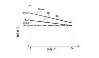
- the fully charged electricity amount Dmax (indicated by a one-dot chain line) that can be taken out from the fully charged state of the assembled battery 110 is the performance guarantee period Ta from the time of a new vehicle (full charged electricity amount Dmax1). (In the first embodiment, 10 years), it gradually decreases until the elapsed time (full charge electricity amount Dmax2).
- the upper limit electric quantity Da (indicated by a solid line) is gradually decreased from the time of a new vehicle (upper limit electric quantity Da1) until the performance guarantee period Ta has elapsed (upper limit electric quantity Da2). , It is less than the fully charged electricity amount Dmax. Thereby, the difference between the upper limit electric quantity Da and the fully charged electric quantity Dmax becomes smaller as the deterioration of the assembled battery 110 progresses.
- the relationship between the fully charged electricity amount Dmax and the upper limit electricity amount Da to be set shown in FIG. 4 is stored in the ECU 120 in the form of a table, and based on this data, the fully charged electricity amount is stored.
- the upper limit electric quantity Da is set from the quantity Dmax.
- the relationship between the fully charged electricity amount Dmax and the upper limit electricity amount Da is stored in the ECU 120 in the form of a function, and based on this, the upper limit electricity amount Da is set from the fully charged electricity amount Dmax. Good.
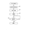
- step S1 the current deterioration state of the assembled battery 110 is determined.
- the internal resistance R of the assembled battery 110 is measured, and from the value of the internal resistance R, the amount of electricity that can be taken out from the fully charged state (full charge electricity amount Dmax) is obtained.
- the relationship between the internal resistance R of the assembled battery 110 and the fully charged electric charge Dmax is stored in the ECU 120 in the form of a table, and based on this data, the current internal resistance The current fully charged electricity amount Dmax is obtained from R.
- the relationship between the internal resistance R and the full charge electric quantity Dmax may be stored in the ECU 120 in the form of a function, and based on this, the full charge electric quantity Dmax may be obtained from the internal resistance R.
- the method for determining the deterioration of the assembled battery 110 is not limited to this.
- the full charge electricity amount Dmax can be obtained by measuring the battery capacity of the assembled battery 110 by performing full charge and complete discharge prior to plug-in charge.
- the travel distance, traveling time, vehicle leaving time, energized charge amount to the assembled battery 110, temperature history of the assembled battery 110, current rate history of the assembled battery 110, assembled battery 110 The SOC history, the resistance increase rate of the assembled battery 110, the charge capacity, the discharge capacity, and the like can be used as appropriate.
- step S2 After determining the deterioration degree of the assembled battery 110, the process proceeds to step S2, and the ECU 120 sets the upper limit electric quantity Da.
- the ECU 120 stores the relationship between the full charge electricity amount Dmax and the upper limit electricity amount Da to be set in the form of a table. Based on this data, the full charge obtained in step S1 is stored.
- the upper limit electric quantity Da is set directly from the electric quantity Dmax.
- ECU120 which is performing step S1 and step S2 is equivalent to the above-mentioned upper limit electric quantity setting means.
- step S3 it progresses to step S3 and the charge of the assembled battery 110 is started.
- step S4 it is determined whether or not the upper limit electricity amount Da has been reached. That is, the amount of electricity D that can be currently taken out from the assembled battery 110 is obtained, and it is determined whether or not the amount of electricity D has reached the upper limit electricity amount Da.
- NO that is, when the electric amount D of the assembled battery 110 has not yet reached the upper limit electric amount Da
- the assembled battery 110 is continuously charged.
- YES that is, if the amount of electricity D of the assembled battery 110 has reached the upper limit amount of electricity Da
- this plug-in charging is terminated.
- ECU120 which performs step S3 and step S4 is corresponded to the above-mentioned charging means.
- the upper limit electricity amount Da is set when plug-in charging is performed.
- the upper limit electricity amount Da is periodically (for example, every month) together with or separately from this. It may be set to update the upper limit electricity quantity Da.
- FIG. 2 shows the case where plug-in charging is performed.
- the latest upper limit electricity quantity Da set before this charging (for example, the upper limit electricity quantity Da set and updated periodically every month) can be used.
- the ECU 120 sets the upper limit electric quantity Da that can be taken out from the assembled battery 110 to be lower than that in the fully charged state (steps S1 and S2).
- the assembled battery 110 is charged with the amount Da as an upper limit (steps S3 and S4).
- the battery system according to the first embodiment has a large capacity deterioration rate Fm of the assembled battery 110 after the performance guarantee period Ta (for example, 10 years) has elapsed.
- the capacity deterioration rate Fa of the assembled battery 110 after the performance guarantee period Ta has elapsed is sufficiently small.
- the capacity deterioration rate F (%) indicates the ratio of the decrease in battery capacity due to deterioration to the battery capacity of the assembled battery 110 when new.
- the upper limit electric quantity Da is set to a value where the difference between and gradually decreases (see FIG. 4). For this reason, even if the battery pack 110 deteriorates, the amount of electricity D that can be taken out from the battery pack 110 when it is charged up to the upper limit electricity amount Da is gradually reduced as compared to the battery pack 110 deterioration. It does not decrease as much as the deterioration of the assembled battery 110.
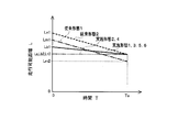
- the battery system 100 it is possible to ensure a sufficient amount of electricity D that can be charged and discharged stably over a long period of time. Specifically, the guaranteed amount of electricity D or more can be taken out from the assembled battery 110 over a performance guarantee period (for example, 10 years). Therefore, in the plug-in hybrid car 200 equipped with the battery system 100, it is possible to sufficiently secure the travelable distance after charging for a long period of time. Specifically, in the plug-in hybrid car 200, a predetermined travelable distance (for example, 30 km) can be ensured over a performance guarantee period (for example, 10 years).
- the travelable distance Ln1 at the time of the new vehicle is made considerably larger than the guaranteed travelable distance La, and the travelable distance Ln2 is greatly reduced after the performance guarantee period Ta has elapsed.
- the travelable distance Lb2 after the performance guarantee period Ta has elapsed does not decrease so much and the initial battery capacity to be mounted is reduced (when the battery capacity is the same as that of the conventional embodiment 1), the guaranteed travel A possible distance La (for example, 30 km) can be secured.
- the plug-in hybrid car 200 has an upper limit according to the deterioration degree of the assembled battery 110 at that time by the ECU 120 (steps S1 and S2) when performing plug-in charging.
- the electric quantity Da is set. It is considered that plug-in charging can often be performed for a long time, for example, from night to morning. Therefore, unlike charging for a short time by regenerative braking during traveling, for example, it is considered that charging to the upper limit electric quantity Da is often performed.
- the plug-in hybrid car 200 when plug-in charging is performed, the upper limit electric quantity Da is set according to the deterioration level of the assembled battery 110 at that time. Thereby, the more suitable upper limit electric quantity Da according to the deterioration condition of the assembled battery 110 at that time can be set, and appropriate plug-in charging can be performed.
- the ECU 122 sets the upper limit electric quantity Db to a value where the difference between the full charge electric quantity Dmax and the upper limit electric quantity Db becomes smaller as the deterioration of the assembled battery 110 progresses, as in the first embodiment. Is set directly, but the set value is different from the upper limit electric quantity Da of the first embodiment.
- the upper limit electric quantity Db is fixed to a constant value. That is, as shown in FIG. 4, the fully charged electricity amount Dmax (indicated by the alternate long and short dash line) that can be taken out from the fully charged state of the assembled battery 110 is the performance guarantee period Ta (for example, 10 It gradually decreases until the year) (full charge electricity amount Dmax2).
- the upper limit electric quantity Db (indicated by a two-dot chain line) is a constant value from the time of the new vehicle to after the performance guarantee period Ta has elapsed. Thereby, the difference between the upper limit electric charge Db and the fully charged electric charge Dmax becomes smaller as the deterioration of the assembled battery 110 progresses.
- the electric quantity D that can be taken out from the battery pack 110 can be made constant when the battery is charged up to the upper limit electric quantity Db. it can. Therefore, in the battery system 102 of the second embodiment, the magnitude of the amount of electricity D that can be discharged and charged can be constant over a long period of time. Therefore, in the plug-in hybrid car 202 equipped with this, the travelable distance after charging can be made constant over a long period of time. Specifically, a constant travelable distance (for example, 30 km) can always be ensured over a performance guarantee period (for example, 10 years). That is, as shown by a two-dot chain line in FIG.
- the travelable distance at the time of the new vehicle and the travelable distance after the performance guarantee period Ta have not changed, and a constant guaranteed travelable distance La (for example, 30 km) can be secured.
- the same parts as those of the first embodiment have the same effects as those of the first embodiment.
- an upper limit SOC is set as an index corresponding to the upper limit electric quantity, and this upper limit SOC is set. It differs from the battery system 100 and the plug-in hybrid car 200 of the first embodiment in that the assembled battery 110 is charged as the upper limit. Other than that, it is basically the same as in the first embodiment, and therefore the description of the same parts as in the first embodiment is omitted or simplified.
- the ECU 123 sets the upper limit SOC having a value smaller than SOC 100%, thereby indirectly setting the upper limit electric quantity corresponding thereto, and setting the upper limit SOC corresponding to this upper limit electric quantity as the upper limit.
- the battery pack 110 is charged.
- the setting of the upper limit SOC (setting of the upper limit electricity amount) is performed when the assembled battery 110 is charged.
- the upper limit SOC (upper limit electric quantity) is set when plug-in charging is performed by connecting to the external power source XV.
- the upper limit SOC is set to a value that increases as the deterioration of the assembled battery 110 proceeds (in the third embodiment, a value that gradually increases gradually).
- the relationship between the capacity deterioration rate F and the upper limit SOC to be set is stored in the ECU 123 in the form of a table, and the upper limit SOC is set from the capacity deterioration rate F based on this data.
- the relationship between the capacity deterioration rate F and the upper limit SOC may be stored in the ECU 123 in the form of a function, and based on this, the upper limit SOC may be set from the capacity deterioration rate F.
- the plug-in hybrid car 203 is connected to the external power source XV, and plug-in charging is started. Then, in step S21, the current deterioration level of the assembled battery 110 is determined. In the third embodiment, the internal resistance R of the assembled battery 110 is measured, and the current capacity deterioration rate F of the assembled battery 110 is obtained from the value of the internal resistance R.
- the relationship between the internal resistance R and the capacity deterioration rate F of the assembled battery 110 is stored in the ECU 123 in the form of a table, and based on this data, the current internal resistance R To obtain the current capacity deterioration rate F.
- the relationship between the internal resistance R and the capacity deterioration rate F may be stored in the ECU 123 as a function, and the capacity deterioration rate F may be obtained from the internal resistance R based on this relationship.
- step S22 it progresses to step S22 and ECU123 sets upper limit SOC.
- the relationship between the capacity deterioration rate F and the upper limit SOC to be set is stored in the form of a table in the ECU 123, based on this data, from the capacity deterioration rate F obtained in step S21.
- ECU123 which performs step S21 and step S22 is corresponded to the above-mentioned upper limit SOC setting means, and is also equivalent to the above-mentioned upper limit electric quantity setting means.
- step S23 it progresses to step S23 and charge of the assembled battery 110 is started.
- step S24 the process proceeds to step S24 to determine whether or not the upper limit SOC has been reached. That is, the current SOC of the battery pack 110 is obtained from the battery voltage, and it is determined whether or not this SOC has reached the upper limit SOC.
- NO that is, if the SOC of the assembled battery 110 has not yet reached the upper limit SOC
- the assembled battery 110 is continuously charged.
- YES that is, if the SOC of the assembled battery 110 has reached the upper limit SOC
- this plug-in charging is terminated.
- ECU123 which performs step S23 and step S24 is equivalent to the above-mentioned charging means.
- the upper limit SOC is set when performing plug-in charging.
- the upper limit SOC is set periodically (for example, every month) together with or separately from this, The upper limit SOC may be updated.
- the current SOC of the assembled battery 110 is obtained from the battery voltage, but the method for obtaining the SOC is not limited to this.
- the SOC of the assembled battery 110 can be obtained by integrating the amount of electricity D that enters and exits the assembled battery 110 from the current flowing through the assembled battery 110.
- FIG. 6 shows a case where plug-in charging is performed, but charging is also terminated when the assembled battery 110 reaches the upper limit SOC even when charging by a regenerative brake or the like during traveling. In the charging by the regenerative brake or the like, the latest upper limit SOC set before the charging (for example, the upper limit SOC that is periodically set and updated every month) can be used.
- the ECU 123 sets the upper limit SOC smaller than the SOC 100% (steps S21 and S22), and charges the assembled battery 110 with the upper limit SOC as an upper limit ( Steps S23 and S24).
- the upper limit of the SOC in this way, the progress of deterioration of the assembled battery 110 can be suppressed (see FIG. 3).
- the capacity of the assembled battery 110 required in consideration of future deterioration can be reduced, and the initial capacity of the assembled battery 110 mounted on the battery system 103 can be reduced.
- the upper limit SOC is set to a larger value as the deterioration of the assembled battery 110 progresses. For this reason, even if the battery pack 110 deteriorates, the amount of electricity D that can be taken out from the battery pack 110 when the battery is charged to the upper limit SOC gradually decreases with respect to the battery pack deterioration. Not as bad as deterioration. Therefore, the battery system 103 can secure a sufficient amount of electricity D that can be charged and discharged stably over a long period of time. Specifically, the guaranteed amount of electricity D or more can be taken out from the assembled battery 110 over a performance guarantee period (for example, 10 years).
- the plug-in hybrid car 203 equipped with the battery system 103 can sufficiently secure a travelable distance after charging for a long period of time.
- a predetermined travelable distance for example, 30 km
- a performance guarantee period for example, 10 years
- the plug-in hybrid car 203 of the third embodiment has an upper limit according to the deterioration degree of the assembled battery 110 at that time by the ECU 123 (steps S21 and S22) when performing plug-in charging.
- Set the SOC Since it is considered that plug-in charging can often be charged up to the upper limit electric quantity SOC, when plug-in charging is performed, the upper limit SOC is set according to the degree of deterioration of the assembled battery 110 at that time. Therefore, it is possible to set a more appropriate upper limit SOC corresponding to the deterioration degree of the assembled battery 110 and to perform appropriate plug-in charging.
- the same parts as those in the first or second embodiment have the same effects as those in the first or second embodiment.
- the upper limit SOC value to be set is different from the upper limit SOC according to the third embodiment.
- the description of the same parts as in the third embodiment is omitted or simplified.
- the ECU 124 indirectly sets the upper limit electric quantity by setting the upper limit SOC to a value that increases as the deterioration of the assembled battery 110 progresses, as in the third embodiment.
- the set value is different from the upper limit SOC of the third embodiment (therefore, the upper limit electricity corresponding thereto).
- the upper limit SOC is set.
- the amount of electricity D that can be taken out from the battery pack 110 when the battery pack is charged up to the upper limit SOC can be made constant. Therefore, in the battery system 104 of the fourth embodiment, the amount of electricity D that can be discharged and charged can be made constant over a long period of time. Therefore, in the plug-in hybrid car 204 equipped with this, the travelable distance after charging can be made constant over a long period of time. Specifically, a constant travelable distance (for example, 30 km) can always be ensured over a performance guarantee period (for example, 10 years) (see FIG. 5).
- the same parts as in any of Embodiments 1 to 3 have the same operational effects as in any of Embodiments 1 to 3.
- the ECU 125 directly sets the upper limit electric quantity Da that can be taken out from the assembled battery 110 as in the first embodiment, and charges the assembled battery 110 with the upper limit electric quantity Da as an upper limit.
- a predetermined condition such as when an additional increase in power consumption is expected due to the use of auxiliary equipment such as a heater or an air conditioner
- the upper limit electric quantity Da is not set as the upper limit
- the upper limit electric quantity Da is not set as the upper limit.
- the assembled battery 110 can be charged beyond Da.
- the plug-in hybrid car 205 is connected to the external power source XV, and plug-in charging is started. Then, in step S31, the region and season of the current vehicle location are determined. For the determination of the region and season, for example, position information by a navigation system, information such as date, season, and weather from the Internet can be used.
- step S32 it is determined whether or not the power consumption of the auxiliary machinery is likely to increase. Specifically, based on the current vehicle location and season information obtained in step S31, it is determined whether or not it is assumed that the amount of additional power used by auxiliary devices such as heaters and air conditioners will increase. . In this determination, for example, the usage history of the auxiliary equipment during the previous travel (the actual power usage) can be used.
- step S33 the upper limit electric quantity Da set before the plug-in charging is canceled. Then, it progresses to step S34 and charge of the assembled battery 110 is started. And it progresses to step S35 and it is judged whether the assembled battery 110 became the state of full charge. Here, if NO, that is, if the assembled battery 110 is not yet fully charged, the assembled battery 110 is continuously charged. On the other hand, if YES, that is, if the assembled battery 110 is fully charged, the plug-in charging is terminated.
- the ECU 125 executing steps S33 to S35 corresponds to the above-described upper limit electric quantity canceling means.
- step S36 determines whether the present electric quantity D of the assembled battery 110 reached the upper limit electric quantity Da, and when reaching the upper limit electric quantity Da, this plug-in charge is complete
- the ECU 125 executing step S36 and step S37 corresponds to the aforementioned upper limit electric quantity setting means
- the ECU 125 executing step S38 and step S39 corresponds to the aforementioned charging means. .
- step S32 when it is assumed that the power consumption of the auxiliary machinery is increased in advance (step S32), the upper limit electricity amount Da is canceled (step S33) and the battery is fully charged. Charging is performed until it becomes (steps S34 and S35). However, after the upper limit electric quantity Da is canceled (step S33), a second upper limit electric quantity that is larger than the released upper limit electric quantity Da but smaller than that in the fully charged state is newly set. You may make it charge the assembled battery 110 by making an upper limit electric quantity into an upper limit.
- the assembled battery 110 can be charged beyond the upper limit electric quantity Da without setting the upper limit electric quantity Da as an upper limit. It is. For this reason, even when it is assumed that power consumption is increased in advance, such as using a heater or an air conditioner, it is possible to sufficiently secure the travelable distance.
- the amount of electricity D that can be charged / discharged due to the memory effect may decrease due to repeated charging / discharging of the assembled battery 110. is there.
- the battery system 105 of the fifth embodiment since the assembled battery 110 can be charged exceeding the upper limit electric quantity Da, for example, by discharging to SOC 0% once and then charging to SOC 100%, The assembled battery 110 can be refreshed. For this reason, even if a memory effect occurs in the assembled battery 110, this memory effect can be eliminated.
- the same parts as in any of Embodiments 1 to 4 have the same operational effects as in any of Embodiments 1 to 4.
- the upper limit SOC is used as an index corresponding to the upper limit electric quantity Da. That is, in step S33 of FIG. 7, instead of releasing the set upper limit electric quantity Da, the set upper limit SOC is released. In steps S36 to S39 of FIG. 7, instead of directly setting the upper limit electricity quantity Da, an upper limit SOC is set as an index corresponding to the upper limit electricity quantity Da, and the assembled battery is set with this upper limit SOC as an upper limit. 110 is charged. That is, steps S21 to S24 (see FIG. 6) described in the third embodiment are performed.
- the ECU 126 executing steps S33 to S35 corresponds to the above-described upper limit SOC canceling means, and also corresponds to the upper limit electric quantity canceling means. Further, the ECU 126 executing step S36 and step S37 corresponds to the above-described upper limit SOC setting unit and upper limit electric quantity setting unit, and the ECU 126 executing step S38 and step S39 corresponds to the above-described charging unit. To do.
- the assembled battery 110 can be charged beyond the upper limit SOC without setting the upper limit SOC as an upper limit. For this reason, even when it is assumed that power consumption is increased in advance, such as using a heater or an air conditioner, it is possible to sufficiently secure the travelable distance.
- the amount of electricity D that can be charged / discharged to the assembled battery 110 by the memory effect may decrease due to repeated charging and discharging.
- the assembled battery 110 can be charged beyond the upper limit SOC, the assembled battery can be charged by, for example, once discharging to SOC 0% and then charging to SOC 100%. 110 can be refreshed. For this reason, even if a memory effect occurs in the assembled battery 110, this memory effect can be eliminated.
- the same parts as in any of the first to fifth embodiments have the same effects as any of the first to fifth embodiments.
- the present invention has been described with reference to the first to sixth embodiments.
- the present invention is not limited to the above-described first to sixth embodiments, and can be appropriately modified and applied without departing from the spirit of the present invention. Needless to say, you can.
- the assembled battery including a lithium secondary battery is exemplified as the secondary battery.
- the present invention is applicable to other types of secondary batteries such as a nickel hydrogen battery and a nickel cadmium battery. Can be applied.
- the first to sixth embodiments when plug-in charging is performed, the deterioration degree of the assembled battery 110 at that time is determined, the upper limit electric quantity Da and the upper limit SOC are set, and these are set as upper limits. Is charging. However, plug-in charging is performed using the latest upper limit electric quantity Da and upper limit SOC (for example, upper limit electric quantity Da and upper limit SOC set and updated periodically every month) set before plug-in charging is performed. You may do it.
Landscapes
- Engineering & Computer Science (AREA)
- Power Engineering (AREA)
- Mechanical Engineering (AREA)
- Transportation (AREA)
- Chemical Kinetics & Catalysis (AREA)
- General Chemical & Material Sciences (AREA)
- Electrochemistry (AREA)
- Chemical & Material Sciences (AREA)
- Manufacturing & Machinery (AREA)
- Life Sciences & Earth Sciences (AREA)
- Sustainable Development (AREA)
- Sustainable Energy (AREA)
- Electric Propulsion And Braking For Vehicles (AREA)
- Secondary Cells (AREA)
- Charge And Discharge Circuits For Batteries Or The Like (AREA)
Abstract
Description
また、特許文献2の電気自動車は、使用者が充電モードを選択するものであるため、例えば、常にロングドライブモードに設定したままであると、満充電やそれに近い充電が繰り返し行われることとなり、二次電池の劣化進行が早まる。また、充電モードの選択が面倒である。
また、上限電気量設定手段により「上限電気量を設定する」とは、「上限電気量」の値自身を直接的に設定する場合が挙げられる。その他、二次電池の劣化が進行する各時点において、「上限電気量」に対応する二次電池の端子間電圧(上限端子間電圧)やSOC(上限SOC)など、「上限電気量」に対応した指標を設定することにより、「上限電気量」を間接的に設定する場合も含まれる。なお、SOC(State Of Charge)は、電池の残容量であり、電池の充電状態を示すものである。
なお、メモリ効果の生じる特性を有する二次電池としては、例えば、ニッケル水素電池やニッケルカドミウム電池、一部のリチウム電池などが挙げられる。
また、前述の電気システムは、二次電池の劣化が進行しても、上限電気量まで充電した場合に、この二次電池から取り出し得る電気量を、二次電池の劣化ほどには低下しないようにできるため、この電池システム搭載車両は、長期間に亘り、充電後の走行可能距離を十分に確保できる。
更に、上限電気量を一定の値に固定した場合には、前述のように、電池システムは、長期間に亘り、充放電し得る電気量の大きさを一定とすることができるため、この電池システム搭載車両は、長期間に亘り、充電後の走行可能距離を一定とすることができる。
なお、「電池システム搭載車両」としては、例えば、電気自動車、プラグインハイブリッドカー、ハイブリッドカー、ハイブリッド鉄道車両、フォークリフト、電気車いす、電動アシスト自転車、電動スクータなどが挙げられる。
なお、「SOC(State Of Charge)」は、前述のように、二次電池の残容量であり、二次電池の充電状態を示すものである。SOCは、電圧検知、電流積算等により推定することができる。
また、前述の電気システムは、二次電池の劣化が進行しても、上限SOCまで充電した場合に、この二次電池から取り出し得る電気量を、二次電池の劣化ほどには低下しないようにできるため、この電池システム搭載車両は、長期間に亘り、充電後の走行可能距離を十分に確保できる。
更に、前述の上限SOC解除手段を備える場合には、上限SOCを超えて二次電池を充電することが可能となるため、ヒータやエアコンなどの補機を駆動させるなど、消費電力が大きくなると予め想定される場合などでも、充電後の走行可能距離を十分に確保できる。
110 組電池(二次電池)
120,122,123,124,125,126 ECU
130 インバータ
140 AC-DCコンバータ
150 ケーブル
160 プラグ付きケーブル
200,202,203,204,205,206 プラグインハイブリッドカー(電池システム搭載車両)
210 車体
220 エンジン
230 フロントモータ
240 リアモータ
XV 外部電源
以下、本発明の実施の形態を、図面を参照しつつ説明する。図1に、本実施形態1に係る電池システム100を搭載したプラグインハイブリッドカー(電池システム搭載車両)200を示す。このプラグインハイブリッドカー200は、その車体210に、エンジン220、フロントモータ230、リアモータ240及び電池システム100を搭載する。
上限電気量Daの設定は、組電池110を充電する際に行う。具体的には、例えば家庭用外部電源などの外部電源XVにプラグインハイブリッドカー200を接続して、外部電源XVによるプラグイン充電を行う際に、この上限電気量Daを設定する。
まず、外部電源XVにプラグインハイブリッドカー200を接続して、プラグイン充電を開始する。すると、ステップS1において、組電池110の現在の劣化具合を判定する。本実施形態1では、組電池110の内部抵抗Rを測定し、この内部抵抗Rの値から、満充電状態から取り出し得る電気量(満充電電気量Dmax)を求める。
なお、内部抵抗Rと満充電電気量Dmaxとの関係を関数の形でECU120内に記憶させておき、これに基づいて、内部抵抗Rから満充電電気量Dmaxを求めるようにしてもよい。
なお、ステップS1及びステップS2を実行しているECU120が、前述の上限電気量設定手段に相当する。
なお、ステップS3及びステップS4を実行しているECU120が、前述の充電手段に相当する。
また、図2には、プラグイン充電を行う場合を示したが、走行中の回生ブレーキ等による充電を行う場合にも、組電池110の電気量Dが上限電気量Daに達した場合には充電を終了する。この回生ブレーキ等による充電では、この充電時以前に設定された最新の上限電気量Da(例えば1ヶ月毎に定期的に設定し更新した上限電気量Da)を用いることができる。
次いで、第2の実施の形態について説明する。本実施形態2の電池システム102及びこれを搭載したプラグインハイブリッドカー202では、設定する上限電気量Dbの値が、上記実施形態1に係る上限電気量Daと異なる。それ以外は、基本的に上記実施形態1と同様であるので、上記実施形態1と同様な部分の説明は、省略または簡略化する。
具体的には、本実施形態2では、上限電気量Dbを一定の値に固定する。即ち、図4に示すように、組電池110の満充電状態から取り出し得る満充電電気量Dmax(一点鎖線で示す)は、新車時(満充電電気量Dmax1)から、性能保証期間Ta(例えば10年間)経過後(満充電電気量Dmax2)まで徐々に低下していく。これに対し、上限電気量Db(二点鎖線で示す)は、新車時から、性能保証期間Ta経過後まで一定の値とする。これにより、上限電気量Dbは、組電池110の劣化が進行するほど、満充電電気量Dmaxとの差が小さくなる。
よって、これを搭載したプラグインハイブリッドカー202では、長期間に亘り、充電後の走行可能距離を一定とすることができる。具体的には、性能保証期間(例えば10年間)に亘り、常に一定の走行可能距離(例えば30km)を確保できる。即ち、図5に二点鎖線で示すように、新車時の走行可能距離も性能保証期間Ta経過後(例えば10年後)の走行可能距離も変わらず、常に一定の保証走行可能距離La(例えば30km)を確保できる。その他、上記実施形態1と同様な部分は、上記実施形態1と同様な作用効果を奏する。
次いで、第3の実施の形態について説明する。本実施形態3の電池システム103及びこれを搭載したプラグインハイブリッドカー203では、上限電気量を直接的に設定する代わりに、上限電気量に対応する指標として上限SOCを設定し、この上限SOCを上限として組電池110の充電を行う点が、上記実施形態1の電池システム100及びプラグインハイブリッドカー200と異なる。それ以外は、基本的に上記実施形態1と同様であるので、上記実施形態1と同様な部分の説明は、省略または簡略化する。
上限SOCの設定(上限電気量の設定)は、組電池110を充電する際に行う。具体的には、外部電源XVに接続してプラグイン充電を行う際に、この上限SOC(上限電気量)を設定する。
まず、外部電源XVにプラグインハイブリッドカー203を接続して、プラグイン充電を開始する。すると、ステップS21において、組電池110の現在の劣化具合を判定する。本実施形態3では、組電池110の内部抵抗Rを測定し、この内部抵抗Rの値から組電池110の現在の容量劣化率Fを求める。
なお、内部抵抗Rと容量劣化率Fとの関係を関数の形でECU123内に記憶させておき、これに基づいて、内部抵抗Rから容量劣化率Fを求めるようにしてもよい。
なお、ステップS21及びステップS22を実行しているECU123が、前述の上限SOC設定手段に相当し、また、前述の上限電気量設定手段にも相当する。
なお、ステップS23及びステップS24を実行しているECU123が、前述の充電手段に相当する。
また、本実施形態3では、電池電圧から組電池110の現在のSOCを求めているが、SOCを求める手法は、これに限定されない。例えば、組電池110に流れた電流から組電池110に出入りした電気量Dを積算して、組電池110のSOCを求めることができる。
また、図6には、プラグイン充電を行う場合を示したが、走行中の回生ブレーキ等による充電を行う場合にも、組電池110が上限SOCに達した場合には充電を終了する。この回生ブレーキ等による充電では、この充電時以前に設定された最新の上限SOC(例えば1ヶ月毎に定期的に設定し更新した上限SOC)を用いることができる。
次いで、第4の実施の形態について説明する。本実施形態4の電池システム104及びこれを搭載したプラグインハイブリッドカー204では、設定する上限SOCの値が、上記実施形態3に係る上限SOCと異なる。それ以外は、基本的に上記実施形態3等と同様であるので、上記実施形態3等と同様な部分の説明は、省略または簡略化する。
よって、これを搭載したプラグインハイブリッドカー204では、長期間に亘り、充電後の走行可能距離を一定とすることができる。具体的には、性能保証期間(例えば10年間)に亘り、常に一定の走行可能距離(例えば30km)を確保できる(図5参照)。その他、上記実施形態1~3のいずれかと同様な部分は、上記実施形態1~3のいずれかと同様な作用効果を奏する。
次いで、第5の実施の形態について説明する。本実施形態5の電池システム105及びこれを搭載したプラグインハイブリッドカー205では、上限電気量Daを解除して組電池110を充電することも可能な点が、上記実施形態1,2の電池システム100,102及びプラグインハイブリッドカー200,202と異なる。それ以外は、基本的に上記実施形態1等と同様であるので、上記実施形態1等と同様な部分の説明は、省略または簡略化する。
まず、外部電源XVにプラグインハイブリッドカー205を接続して、プラグイン充電を開始する。すると、ステップS31において、車両現在地の地域と季節を判定する。この地域や季節の判定には、例えば、ナビゲーションシステムによる位置情報や、インターネットからの月日、季節、天気等の情報などを利用できる。
その後、ステップS34に進んで、組電池110の充電を開始する。そして、ステップS35に進み、組電池110が満充電の状態になったか否かを判断する。ここで、NO、即ち、組電池110がまだ満充電になっていない場合には、継続して組電池110の充電を行う。一方、YES、即ち、組電池110が満充電の状態になった場合には、このプラグイン充電を終了する。
なお、ステップS33~ステップS35を実行しているECU125が、前述の上限電気量解除手段に相当する。
本実施形態5では、ステップS36及びステップS37を実行しているECU125が、前述の上限電気量設定手段に相当し、ステップS38及びステップS39を実行しているECU125が、前述の充電手段に相当する。
次いで、第6の実施の形態について説明する。本実施形態6の電池システム106及びこれを搭載したプラグインハイブリッドカー206では、上限SOCを解除して組電池110を充電することも可能な点が、上記実施形態3,4の電池システム103,104及びプラグインハイブリッドカー203,204と異なる。それ以外は、基本的に上記実施形態3等と同様であるので、上記実施形態3等と同様な部分の説明は、省略または簡略化する。
本実施形態6では、ステップS33~ステップS35を実行しているECU126が、前述の上限SOC解除手段に相当し、また、上限電気量解除手段にも相当する。また、ステップS36及びステップS37を実行しているECU126が、前述の上限SOC設定手段及び上限電気量設定手段に相当し、ステップS38及びステップS39を実行しているECU126が、前述の充電手段に相当する。
例えば、上記実施形態1~6では、二次電池として、リチウム二次電池からなる組電池を例示したが、例えばニッケル水素電池、ニッケルカドミウム電池等の他の種類の二次電池にも、本発明を適用できる。
また、上記実施形態1~6では、プラグイン充電を行う際に、その時点における組電池110の劣化具合を判定して、上限電気量Daや上限SOCを設定し、これらを上限として組電池110の充電を行っている。しかし、プラグイン充電を行う以前に設定した最新の上限電気量Daや上限SOC(例えば1ヶ月毎に定期的に設定し更新した上限電気量Daや上限SOC)を用いて、プラグイン充電を行うようにしてもよい。
Claims (12)
- 二次電池を備え、この二次電池による電気エネルギを動力源に使用する電池システムであって、
前記二次電池から取り出し得る電気量の上限である上限電気量を、満充電の場合よりも低く設定する上限電気量設定手段であって、前記二次電池の劣化が進行するほど、満充電状態から取り出し得る電気量である満充電電気量と前記上限電気量との差が小さくなる値に、前記上限電気量を設定する上限電気量設定手段と、
前記二次電池を充電する際に、前記上限電気量を上限として、前記二次電池を充電する充電手段と、を備える
電池システム。 - 請求項1に記載の電池システムであって、
前記上限電気量設定手段は、
前記上限電気量を一定の値に固定する
電池システム。 - 請求項1または請求項2に記載の電池システムであって、
前記上限電気量を上限とすることなく、前記上限電気量を超えて前記二次電池を充電可能とする上限電気量解除手段を更に備える
電池システム。 - 請求項3に記載の電池システムであって、
前記二次電池が、メモリ効果の生じる特性を有する
電池システム。 - 請求項1~請求項4のいずれか一項に記載の電池システムを搭載した電池システム搭載車両。
- 請求項5に記載の電池システム搭載車両であって、
前記電池システム搭載車両は、外部電源に接続して前記二次電池を充電可能なプラグイン車両であり、
前記外部電源によるプラグイン充電を行う際に、前記上限電気量設定手段により、その時点における前記二次電池の劣化具合に応じて、前記上限電気量を設定する
電池システム搭載車両。 - 二次電池を備え、この二次電池による電気エネルギを動力源に使用する電池システムであって、
SOC100%よりも小さい上限SOCを設定する上限SOC設定手段であって、前記二次電池の劣化が進行するほど、前記上限SOCを大きい値に設定する上限SOC設定手段と、
前記二次電池を充電する際に、前記上限SOCを上限として、前記二次電池を充電する充電手段と、を備える
電池システム。 - 請求項7に記載の電池システムであって、
前記上限SOC設定手段は、
前記上限SOCから前記二次電池を放電させたときに、前記二次電池の劣化の進行に拘わらず、前記二次電池から取り出し得る電気量が一定となる値に、前記上限SOCを設定する
電池システム。 - 請求項7または請求項8に記載の電池システムであって、
前記上限SOCを上限とすることなく、前記上限SOCを超えて前記二次電池を充電可能とする上限SOC解除手段を更に備える
電池システム。 - 請求項9に記載の電池システムであって、
前記二次電池が、メモリ効果の生じる特性を有する
電池システム。 - 請求項7~請求項10のいずれか一項に記載の電池システムを搭載した電池システム搭載車両。
- 請求項11に記載の電池システム搭載車両であって、
前記電池システム搭載車両は、外部電源に接続して前記二次電池を充電可能なプラグイン車両であり、
前記外部電源によるプラグイン充電を行う際に、前記上限SOC設定手段により、その時点における前記二次電池の劣化具合に応じて、前記上限SOCを設定する
電池システム搭載車両。
Priority Applications (5)
| Application Number | Priority Date | Filing Date | Title |
|---|---|---|---|
| US13/058,368 US8531154B2 (en) | 2009-06-18 | 2009-06-18 | Battery system and battery system-equipped vehicle |
| JP2010550383A JP5158217B2 (ja) | 2009-06-18 | 2009-06-18 | 電池システム及び電池システム搭載車両 |
| CN200980135405.3A CN102150320B (zh) | 2009-06-18 | 2009-06-18 | 电池系统以及电池系统搭载车辆 |
| PCT/JP2009/061086 WO2010146681A1 (ja) | 2009-06-18 | 2009-06-18 | 電池システム及び電池システム搭載車両 |
| DE112009004957.5T DE112009004957B4 (de) | 2009-06-18 | 2009-06-18 | Batteriesysteme und Fahrzeuge, die mit diesen Batteriesystemen ausgestattet sind |
Applications Claiming Priority (1)
| Application Number | Priority Date | Filing Date | Title |
|---|---|---|---|
| PCT/JP2009/061086 WO2010146681A1 (ja) | 2009-06-18 | 2009-06-18 | 電池システム及び電池システム搭載車両 |
Publications (1)
| Publication Number | Publication Date |
|---|---|
| WO2010146681A1 true WO2010146681A1 (ja) | 2010-12-23 |
Family
ID=43356019
Family Applications (1)
| Application Number | Title | Priority Date | Filing Date |
|---|---|---|---|
| PCT/JP2009/061086 Ceased WO2010146681A1 (ja) | 2009-06-18 | 2009-06-18 | 電池システム及び電池システム搭載車両 |
Country Status (5)
| Country | Link |
|---|---|
| US (1) | US8531154B2 (ja) |
| JP (1) | JP5158217B2 (ja) |
| CN (1) | CN102150320B (ja) |
| DE (1) | DE112009004957B4 (ja) |
| WO (1) | WO2010146681A1 (ja) |
Cited By (4)
| Publication number | Priority date | Publication date | Assignee | Title |
|---|---|---|---|---|
| AT508875A3 (de) * | 2011-01-21 | 2012-06-15 | Avl List Gmbh | Betrieb eines elektrischen energiespeichers für ein fahrzeug |
| US20140097676A1 (en) * | 2011-06-07 | 2014-04-10 | Toyota Jidosha Kabushiki Kaisha | Electrically powered vehicle and method for controlling electrically powered vehicle |
| JP2023137939A (ja) * | 2022-03-18 | 2023-09-29 | プライムアースEvエナジー株式会社 | ニッケル水素蓄電池の回復方法及び回復装置 |
| WO2025142286A1 (ja) * | 2023-12-27 | 2025-07-03 | 株式会社Gsユアサ | 蓄電情報処理方法、蓄電情報処理装置、及びコンピュータプログラム |
Families Citing this family (28)
| Publication number | Priority date | Publication date | Assignee | Title |
|---|---|---|---|---|
| CN102648104B (zh) * | 2009-11-17 | 2015-04-22 | 丰田自动车株式会社 | 车辆及车辆的控制方法 |
| US8346423B2 (en) * | 2010-06-07 | 2013-01-01 | Ford Global Technologies, Llc | Plug-in electric vehicle interlock |
| US8365858B2 (en) * | 2010-12-27 | 2013-02-05 | Mazda Motor Corporation | Harness arrangement structure of vehicle |
| US8890467B2 (en) * | 2011-03-28 | 2014-11-18 | Continental Automotive Systems, Inc. | System for controlling battery conditions |
| US10234512B2 (en) * | 2011-06-11 | 2019-03-19 | Sendyne Corporation | Current-based cell modeling |
| RU2561162C1 (ru) * | 2011-10-07 | 2015-08-27 | Тойота Дзидося Кабусики Кайся | Система зарядки транспортного средства и способ зарядки транспортного средства |
| JP5880008B2 (ja) * | 2011-12-19 | 2016-03-08 | マツダ株式会社 | 車載用電源の制御装置 |
| JP5998755B2 (ja) * | 2012-08-30 | 2016-09-28 | マツダ株式会社 | 車両用電源制御装置および方法 |
| JP5655838B2 (ja) * | 2012-10-25 | 2015-01-21 | トヨタ自動車株式会社 | 電池システム |
| JP6099743B2 (ja) * | 2013-06-07 | 2017-03-22 | 三菱電機株式会社 | 充放電制御装置および電動車両 |
| JP2015014487A (ja) * | 2013-07-03 | 2015-01-22 | パナソニックIpマネジメント株式会社 | 車両用蓄電池管理装置、車両用電力装置、および車両用蓄電池の管理方法 |
| CN104348193A (zh) * | 2013-07-25 | 2015-02-11 | 观致汽车有限公司 | 电池管理系统和方法、以及包括该系统的车辆 |
| JP5765375B2 (ja) * | 2013-07-25 | 2015-08-19 | トヨタ自動車株式会社 | 制御装置及び制御方法 |
| JP2015117633A (ja) * | 2013-12-18 | 2015-06-25 | トヨタ自動車株式会社 | 充電制御装置 |
| FR3026355B1 (fr) * | 2014-09-30 | 2017-12-29 | Bluetram | Procede et systeme d'assistance au positionnement d'un vehicule electrique par rapport a une station de recharge, station de recharge et vehicule electrique mettant en œuvre ce procede |
| KR101763502B1 (ko) * | 2015-02-24 | 2017-07-31 | 가부시끼가이샤 도시바 | 축전지 관리 장치, 방법 및 프로그램 |
| CN105799536B (zh) * | 2016-05-06 | 2018-11-02 | 重庆长安汽车股份有限公司 | 一种动力电池消除记忆效应的控制方法及系统 |
| WO2018128703A2 (en) * | 2016-11-04 | 2018-07-12 | Black & Decker Inc. | Battery system |
| DE102016224181A1 (de) * | 2016-12-06 | 2018-06-07 | Robert Bosch Gmbh | Verfahren zum Laden eines elektrochemischen Energiespeichers, ein Batteriemanagementsystem, ein Batteriesystem und eine Verwendung des Batteriesystems |
| KR102137759B1 (ko) * | 2017-07-06 | 2020-07-24 | 주식회사 엘지화학 | 배터리 팩 관리 장치 |
| JP6577981B2 (ja) * | 2017-08-03 | 2019-09-18 | 本田技研工業株式会社 | 電源システム |
| EP3498520B1 (en) * | 2017-12-18 | 2023-05-03 | Volvo Car Corporation | Method and system for providing an advice to an occupant of an electrical vehicle |
| KR20210016134A (ko) * | 2019-07-31 | 2021-02-15 | 주식회사 엘지화학 | 배터리 상태 예측 장치 및 배터리 상태 예측 방법 |
| JP7456900B2 (ja) * | 2020-09-15 | 2024-03-27 | 本田技研工業株式会社 | 電力管理装置および電力管理システム |
| JP7363728B2 (ja) * | 2020-09-25 | 2023-10-18 | トヨタ自動車株式会社 | 電気自動車の電池の管理装置 |
| FR3117272B1 (fr) * | 2020-12-03 | 2023-04-07 | Commissariat Energie Atomique | Procédé de gestion de l’état de charge ou de l’état d’énergie d’un accumulateur pour un vieillissement optimisé |
| US20220250504A1 (en) * | 2021-02-09 | 2022-08-11 | Ford Global Technologies, Llc | Recovery strategies for battery capacity data loss and control related to same |
| GB2621328B (en) * | 2022-08-05 | 2024-10-30 | Caterpillar Inc | Method for monitoring a state of charge of a battery of an electric work vehicle |
Citations (10)
| Publication number | Priority date | Publication date | Assignee | Title |
|---|---|---|---|---|
| JPH08331704A (ja) * | 1995-05-30 | 1996-12-13 | Honda Motor Co Ltd | 電気推進車両およびそのバッテリ出力設定方法 |
| JP2000030753A (ja) * | 1998-07-15 | 2000-01-28 | Nissan Motor Co Ltd | ハイブリッド車両用電池の制御装置 |
| JP3161215B2 (ja) * | 1994-03-15 | 2001-04-25 | 日産自動車株式会社 | 2次電池の充放電制御装置 |
| JP2001157369A (ja) * | 1999-11-26 | 2001-06-08 | Sanyo Electric Co Ltd | 電池の充放電制御方法 |
| JP2001268708A (ja) * | 2000-03-21 | 2001-09-28 | Nissan Motor Co Ltd | ハイブリッド車両の制御装置 |
| JP2003047108A (ja) * | 2001-08-03 | 2003-02-14 | Toyota Motor Corp | 電池制御装置 |
| JP2004186087A (ja) * | 2002-12-05 | 2004-07-02 | Matsushita Electric Ind Co Ltd | 蓄電池の制御方法 |
| JP2008201262A (ja) * | 2007-02-20 | 2008-09-04 | Toyota Motor Corp | ハイブリッド車両 |
| JP2008308122A (ja) * | 2007-06-18 | 2008-12-25 | Mazda Motor Corp | 車両用バッテリの制御装置 |
| JP2009027801A (ja) * | 2007-07-18 | 2009-02-05 | Toyota Motor Corp | 電気自動車および電気自動車の二次電池充電方法 |
Family Cites Families (7)
| Publication number | Priority date | Publication date | Assignee | Title |
|---|---|---|---|---|
| JPH03161215A (ja) | 1989-11-17 | 1991-07-11 | Mitsubishi Materials Corp | 平板状チェーン体およびその駆動構造 |
| US5539318A (en) * | 1992-07-16 | 1996-07-23 | Toyota Jidosha Kabushiki Kaisha | Residual capacity meter for electric car battery |
| JP3421398B2 (ja) | 1993-09-03 | 2003-06-30 | 本田技研工業株式会社 | 車両用二次電池の充電制御方法 |
| JP3827980B2 (ja) * | 2001-09-21 | 2006-09-27 | 本田技研工業株式会社 | ハイブリッド車両の制御装置 |
| DE10302860B4 (de) * | 2003-01-22 | 2018-12-06 | Volkswagen Ag | Vorrichtung und Verfahren zum Ermitteln einer Strategie für das Betreiben einer Batterie |
| JP2006304393A (ja) * | 2005-04-15 | 2006-11-02 | Toyota Motor Corp | 電源装置およびその制御方法並びに車両 |
| DE102008008238B4 (de) | 2007-02-15 | 2025-03-13 | Volkswagen Ag | Verfahren zur Ladestrategie eines Hybridantriebs und durchführendes Steuergerät |
-
2009
- 2009-06-18 DE DE112009004957.5T patent/DE112009004957B4/de active Active
- 2009-06-18 US US13/058,368 patent/US8531154B2/en active Active
- 2009-06-18 JP JP2010550383A patent/JP5158217B2/ja active Active
- 2009-06-18 WO PCT/JP2009/061086 patent/WO2010146681A1/ja not_active Ceased
- 2009-06-18 CN CN200980135405.3A patent/CN102150320B/zh active Active
Patent Citations (10)
| Publication number | Priority date | Publication date | Assignee | Title |
|---|---|---|---|---|
| JP3161215B2 (ja) * | 1994-03-15 | 2001-04-25 | 日産自動車株式会社 | 2次電池の充放電制御装置 |
| JPH08331704A (ja) * | 1995-05-30 | 1996-12-13 | Honda Motor Co Ltd | 電気推進車両およびそのバッテリ出力設定方法 |
| JP2000030753A (ja) * | 1998-07-15 | 2000-01-28 | Nissan Motor Co Ltd | ハイブリッド車両用電池の制御装置 |
| JP2001157369A (ja) * | 1999-11-26 | 2001-06-08 | Sanyo Electric Co Ltd | 電池の充放電制御方法 |
| JP2001268708A (ja) * | 2000-03-21 | 2001-09-28 | Nissan Motor Co Ltd | ハイブリッド車両の制御装置 |
| JP2003047108A (ja) * | 2001-08-03 | 2003-02-14 | Toyota Motor Corp | 電池制御装置 |
| JP2004186087A (ja) * | 2002-12-05 | 2004-07-02 | Matsushita Electric Ind Co Ltd | 蓄電池の制御方法 |
| JP2008201262A (ja) * | 2007-02-20 | 2008-09-04 | Toyota Motor Corp | ハイブリッド車両 |
| JP2008308122A (ja) * | 2007-06-18 | 2008-12-25 | Mazda Motor Corp | 車両用バッテリの制御装置 |
| JP2009027801A (ja) * | 2007-07-18 | 2009-02-05 | Toyota Motor Corp | 電気自動車および電気自動車の二次電池充電方法 |
Cited By (7)
| Publication number | Priority date | Publication date | Assignee | Title |
|---|---|---|---|---|
| AT508875A3 (de) * | 2011-01-21 | 2012-06-15 | Avl List Gmbh | Betrieb eines elektrischen energiespeichers für ein fahrzeug |
| AT508875B1 (de) * | 2011-01-21 | 2013-03-15 | Avl List Gmbh | Betrieb eines elektrischen energiespeichers für ein fahrzeug |
| US20140097676A1 (en) * | 2011-06-07 | 2014-04-10 | Toyota Jidosha Kabushiki Kaisha | Electrically powered vehicle and method for controlling electrically powered vehicle |
| US9233613B2 (en) * | 2011-06-07 | 2016-01-12 | Toyota Jidosha Kabushiki Kaisha | Electrically powered vehicle and method for controlling electrically powered vehicle |
| EP2719572A4 (en) * | 2011-06-07 | 2016-03-02 | Toyota Motor Co Ltd | ELECTRIC VEHICLE AND CONTROL METHOD FOR AN ELECTRIC VEHICLE |
| JP2023137939A (ja) * | 2022-03-18 | 2023-09-29 | プライムアースEvエナジー株式会社 | ニッケル水素蓄電池の回復方法及び回復装置 |
| WO2025142286A1 (ja) * | 2023-12-27 | 2025-07-03 | 株式会社Gsユアサ | 蓄電情報処理方法、蓄電情報処理装置、及びコンピュータプログラム |
Also Published As
| Publication number | Publication date |
|---|---|
| JP5158217B2 (ja) | 2013-03-06 |
| DE112009004957T5 (de) | 2012-06-21 |
| CN102150320B (zh) | 2015-06-17 |
| JPWO2010146681A1 (ja) | 2012-11-29 |
| CN102150320A (zh) | 2011-08-10 |
| US20110156644A1 (en) | 2011-06-30 |
| DE112009004957B4 (de) | 2015-02-12 |
| US8531154B2 (en) | 2013-09-10 |
Similar Documents
| Publication | Publication Date | Title |
|---|---|---|
| JP5158217B2 (ja) | 電池システム及び電池システム搭載車両 | |
| US8577529B2 (en) | Control apparatus for vehicle | |
| JP4228086B1 (ja) | 車両 | |
| US20170361729A1 (en) | Method and arrangement for determining a value of the state of energy of a battery in a vehicle | |
| CN102463904A (zh) | 电动汽车可行驶里程预测 | |
| CN109311410B (zh) | 用于对电池组进行热调节的方法和系统 | |
| CN104904092A (zh) | 能量存储控制系统和方法 | |
| JP5515897B2 (ja) | 車両の制御装置およびそれを搭載する車両 | |
| JP2009250970A (ja) | バッテリーの残存容量の推定方法 | |
| JP2016530863A (ja) | エネルギー貯蔵システムのバランス調整を行うための方法及び装置 | |
| US11437827B2 (en) | Control of a relatively low current fed to a battery pack | |
| US12103428B2 (en) | Method for management of an energy storage system of a vehicle | |
| US20210268932A1 (en) | Systems and methods for estimating state of health of an energy storage device | |
| JP2013198179A (ja) | 車両制御装置および車両 | |
| US20200198477A1 (en) | Vehicular charging control system | |
| JP5842907B2 (ja) | 電源制御装置、電源制御方法 | |
| CN116068445A (zh) | 电池组的劣化诊断装置及电池组的劣化诊断方法 | |
| KR101500121B1 (ko) | 보조배터리 전력충전 제어방법 | |
| JP6701699B2 (ja) | バッテリーの制御システム、ハイブリッド車両及びバッテリーの制御方法 | |
| Yang et al. | Plug-in hybrid electric vehicles | |
| JP2006340544A (ja) | 車輌運休中の太陽発電によるバッテリsoc変化を補正する車輌 | |
| JP2025012302A (ja) | 車両の電力システム |
Legal Events
| Date | Code | Title | Description |
|---|---|---|---|
| WWE | Wipo information: entry into national phase |
Ref document number: 200980135405.3 Country of ref document: CN |
|
| ENP | Entry into the national phase |
Ref document number: 2010550383 Country of ref document: JP Kind code of ref document: A |
|
| WWE | Wipo information: entry into national phase |
Ref document number: 13058368 Country of ref document: US |
|
| 121 | Ep: the epo has been informed by wipo that ep was designated in this application |
Ref document number: 09846174 Country of ref document: EP Kind code of ref document: A1 |
|
| WWE | Wipo information: entry into national phase |
Ref document number: 1120090049575 Country of ref document: DE Ref document number: 112009004957 Country of ref document: DE |
|
| 122 | Ep: pct application non-entry in european phase |
Ref document number: 09846174 Country of ref document: EP Kind code of ref document: A1 |