WO2010143343A1 - 冷凍サイクル装置 - Google Patents
冷凍サイクル装置 Download PDFInfo
- Publication number
- WO2010143343A1 WO2010143343A1 PCT/JP2010/002137 JP2010002137W WO2010143343A1 WO 2010143343 A1 WO2010143343 A1 WO 2010143343A1 JP 2010002137 W JP2010002137 W JP 2010002137W WO 2010143343 A1 WO2010143343 A1 WO 2010143343A1
- Authority
- WO
- WIPO (PCT)
- Prior art keywords
- motor
- refrigerant
- electric motor
- refrigeration cycle
- pipe
- Prior art date
Links
Images


Classifications
-
- F—MECHANICAL ENGINEERING; LIGHTING; HEATING; WEAPONS; BLASTING
- F25—REFRIGERATION OR COOLING; COMBINED HEATING AND REFRIGERATION SYSTEMS; HEAT PUMP SYSTEMS; MANUFACTURE OR STORAGE OF ICE; LIQUEFACTION SOLIDIFICATION OF GASES
- F25B—REFRIGERATION MACHINES, PLANTS OR SYSTEMS; COMBINED HEATING AND REFRIGERATION SYSTEMS; HEAT PUMP SYSTEMS
- F25B9/00—Compression machines, plants or systems, in which the refrigerant is air or other gas of low boiling point
- F25B9/06—Compression machines, plants or systems, in which the refrigerant is air or other gas of low boiling point using expanders
-
- F—MECHANICAL ENGINEERING; LIGHTING; HEATING; WEAPONS; BLASTING
- F25—REFRIGERATION OR COOLING; COMBINED HEATING AND REFRIGERATION SYSTEMS; HEAT PUMP SYSTEMS; MANUFACTURE OR STORAGE OF ICE; LIQUEFACTION SOLIDIFICATION OF GASES
- F25B—REFRIGERATION MACHINES, PLANTS OR SYSTEMS; COMBINED HEATING AND REFRIGERATION SYSTEMS; HEAT PUMP SYSTEMS
- F25B49/00—Arrangement or mounting of control or safety devices
- F25B49/02—Arrangement or mounting of control or safety devices for compression type machines, plants or systems
- F25B49/025—Motor control arrangements
-
- F—MECHANICAL ENGINEERING; LIGHTING; HEATING; WEAPONS; BLASTING
- F25—REFRIGERATION OR COOLING; COMBINED HEATING AND REFRIGERATION SYSTEMS; HEAT PUMP SYSTEMS; MANUFACTURE OR STORAGE OF ICE; LIQUEFACTION SOLIDIFICATION OF GASES
- F25B—REFRIGERATION MACHINES, PLANTS OR SYSTEMS; COMBINED HEATING AND REFRIGERATION SYSTEMS; HEAT PUMP SYSTEMS
- F25B2309/00—Gas cycle refrigeration machines
- F25B2309/06—Compression machines, plants or systems characterised by the refrigerant being carbon dioxide
- F25B2309/061—Compression machines, plants or systems characterised by the refrigerant being carbon dioxide with cycle highest pressure above the supercritical pressure
-
- F—MECHANICAL ENGINEERING; LIGHTING; HEATING; WEAPONS; BLASTING
- F25—REFRIGERATION OR COOLING; COMBINED HEATING AND REFRIGERATION SYSTEMS; HEAT PUMP SYSTEMS; MANUFACTURE OR STORAGE OF ICE; LIQUEFACTION SOLIDIFICATION OF GASES
- F25B—REFRIGERATION MACHINES, PLANTS OR SYSTEMS; COMBINED HEATING AND REFRIGERATION SYSTEMS; HEAT PUMP SYSTEMS
- F25B2400/00—General features or devices for refrigeration machines, plants or systems, combined heating and refrigeration systems or heat-pump systems, i.e. not limited to a particular subgroup of F25B
- F25B2400/07—Details of compressors or related parts
- F25B2400/075—Details of compressors or related parts with parallel compressors
-
- F—MECHANICAL ENGINEERING; LIGHTING; HEATING; WEAPONS; BLASTING
- F25—REFRIGERATION OR COOLING; COMBINED HEATING AND REFRIGERATION SYSTEMS; HEAT PUMP SYSTEMS; MANUFACTURE OR STORAGE OF ICE; LIQUEFACTION SOLIDIFICATION OF GASES
- F25B—REFRIGERATION MACHINES, PLANTS OR SYSTEMS; COMBINED HEATING AND REFRIGERATION SYSTEMS; HEAT PUMP SYSTEMS
- F25B2400/00—General features or devices for refrigeration machines, plants or systems, combined heating and refrigeration systems or heat-pump systems, i.e. not limited to a particular subgroup of F25B
- F25B2400/14—Power generation using energy from the expansion of the refrigerant
-
- F—MECHANICAL ENGINEERING; LIGHTING; HEATING; WEAPONS; BLASTING
- F25—REFRIGERATION OR COOLING; COMBINED HEATING AND REFRIGERATION SYSTEMS; HEAT PUMP SYSTEMS; MANUFACTURE OR STORAGE OF ICE; LIQUEFACTION SOLIDIFICATION OF GASES
- F25B—REFRIGERATION MACHINES, PLANTS OR SYSTEMS; COMBINED HEATING AND REFRIGERATION SYSTEMS; HEAT PUMP SYSTEMS
- F25B2500/00—Problems to be solved
- F25B2500/27—Problems to be solved characterised by the stop of the refrigeration cycle
-
- F—MECHANICAL ENGINEERING; LIGHTING; HEATING; WEAPONS; BLASTING
- F25—REFRIGERATION OR COOLING; COMBINED HEATING AND REFRIGERATION SYSTEMS; HEAT PUMP SYSTEMS; MANUFACTURE OR STORAGE OF ICE; LIQUEFACTION SOLIDIFICATION OF GASES
- F25B—REFRIGERATION MACHINES, PLANTS OR SYSTEMS; COMBINED HEATING AND REFRIGERATION SYSTEMS; HEAT PUMP SYSTEMS
- F25B2600/00—Control issues
- F25B2600/02—Compressor control
- F25B2600/021—Inverters therefor
-
- F—MECHANICAL ENGINEERING; LIGHTING; HEATING; WEAPONS; BLASTING
- F25—REFRIGERATION OR COOLING; COMBINED HEATING AND REFRIGERATION SYSTEMS; HEAT PUMP SYSTEMS; MANUFACTURE OR STORAGE OF ICE; LIQUEFACTION SOLIDIFICATION OF GASES
- F25B—REFRIGERATION MACHINES, PLANTS OR SYSTEMS; COMBINED HEATING AND REFRIGERATION SYSTEMS; HEAT PUMP SYSTEMS
- F25B2600/00—Control issues
- F25B2600/02—Compressor control
- F25B2600/025—Compressor control by controlling speed
- F25B2600/0253—Compressor control by controlling speed with variable speed
-
- F—MECHANICAL ENGINEERING; LIGHTING; HEATING; WEAPONS; BLASTING
- F25—REFRIGERATION OR COOLING; COMBINED HEATING AND REFRIGERATION SYSTEMS; HEAT PUMP SYSTEMS; MANUFACTURE OR STORAGE OF ICE; LIQUEFACTION SOLIDIFICATION OF GASES
- F25B—REFRIGERATION MACHINES, PLANTS OR SYSTEMS; COMBINED HEATING AND REFRIGERATION SYSTEMS; HEAT PUMP SYSTEMS
- F25B9/00—Compression machines, plants or systems, in which the refrigerant is air or other gas of low boiling point
- F25B9/002—Compression machines, plants or systems, in which the refrigerant is air or other gas of low boiling point characterised by the refrigerant
- F25B9/008—Compression machines, plants or systems, in which the refrigerant is air or other gas of low boiling point characterised by the refrigerant the refrigerant being carbon dioxide
-
- Y—GENERAL TAGGING OF NEW TECHNOLOGICAL DEVELOPMENTS; GENERAL TAGGING OF CROSS-SECTIONAL TECHNOLOGIES SPANNING OVER SEVERAL SECTIONS OF THE IPC; TECHNICAL SUBJECTS COVERED BY FORMER USPC CROSS-REFERENCE ART COLLECTIONS [XRACs] AND DIGESTS
- Y02—TECHNOLOGIES OR APPLICATIONS FOR MITIGATION OR ADAPTATION AGAINST CLIMATE CHANGE
- Y02B—CLIMATE CHANGE MITIGATION TECHNOLOGIES RELATED TO BUILDINGS, e.g. HOUSING, HOUSE APPLIANCES OR RELATED END-USER APPLICATIONS
- Y02B30/00—Energy efficient heating, ventilation or air conditioning [HVAC]
- Y02B30/70—Efficient control or regulation technologies, e.g. for control of refrigerant flow, motor or heating
Definitions
- the present invention relates to a refrigeration cycle apparatus equipped with an expansion mechanism and a plurality of compression mechanisms for use in a water heater or an air conditioner.
- a power recovery type refrigeration cycle apparatus has been proposed in which the power required to drive the compression mechanism is reduced by the recovery amount.
- an expander-integrated compressor in which an electric motor, a compression mechanism, and an expansion mechanism are connected by a shaft is used.
- FIG. 13 is a block diagram showing the refrigeration cycle apparatus described in Patent Document 1.
- the refrigeration cycle apparatus using the expander-integrated compressor 220 and the second compressor 230 includes a refrigerant circuit 210 and a controller 250 that is a control device.
- a first compression mechanism 221 of the expander-integrated compressor 220 and a second compression mechanism 231 of the second compressor 230 are disposed between the indoor heat exchanger 211 and the outdoor heat exchanger 212. They are arranged in parallel.
- the first compression mechanism 221 is connected to the electric motor 222 and the expansion mechanism 223 via a shaft
- the second compression mechanism 231 is connected to the electric motor 232 via a shaft.
- the controller 250 controls the second compressor 230 so that the high pressure of the refrigeration cycle becomes a predetermined target value. Specifically, if the measured value of the high pressure Ph is higher than the target value, the controller 250 reduces the rotational speed of the electric motor 232 to decrease the discharge amount of the second compression mechanism 231. If the measured value is lower than the target value, the rotational speed of the electric motor 232 is increased and the discharge amount of the second compression mechanism 231 is increased. Thereby, the high pressure Ph can be maintained near the target value, and the refrigeration cycle apparatus can be operated while keeping the COP high.
- an object of the present invention is to make it possible to save energy in a stop operation in a refrigeration cycle apparatus using an expander-integrated compressor and a second compressor.
- the present invention provides a first compression mechanism that compresses a refrigerant, an expansion mechanism that recovers power from the expanding refrigerant, and a first shaft that is coupled to the first compression mechanism and the expansion mechanism by a shaft.
- a first compressor including an electric motor, a second compression mechanism for compressing a refrigerant, a second compression mechanism connected in parallel with the first compression mechanism in a refrigerant circuit, and a shaft coupled to the second compression mechanism
- a second compressor including the second electric motor, a radiator that radiates the refrigerant discharged from the first compression mechanism and the second compression mechanism, and an evaporator that evaporates the refrigerant discharged from the expansion mechanism
- the rotation speed of the second motor is set to the first electric motor.
- a control device for reducing a large reduction rate than the rotational speed of, providing a refrigeration cycle apparatus.
- the displacement amount of the expansion mechanism can be compensated for gradually decreasing by making the decrease rate of the rotation speed of the second motor larger than the decrease rate of the rotation speed of the first motor. Therefore, according to the present invention, the pressure difference between the high pressure and the low pressure of the refrigeration cycle can be quickly reduced, and energy saving in the stop operation can be achieved.
- FIG. 1 is a schematic configuration diagram of a refrigeration cycle apparatus according to a first embodiment of the present invention.
- Mollier diagram showing the refrigeration cycle during the stop operation in the first embodiment The graph which shows the relationship between the time at the time of a stop driving
- Flowchart of stop operation in the first embodiment Schematic block diagram of the refrigeration cycle apparatus according to the second embodiment of the present invention.
- Flowchart of stop operation in the second embodiment The graph which shows the relationship between the time at the time of a stop driving
- FIG. 1 shows a refrigeration cycle apparatus 100A according to a first embodiment of the present invention.
- the refrigeration cycle apparatus 100A includes a refrigerant circuit 3 that circulates refrigerant.
- the refrigerant circuit 3 includes a first compressor (expander-integrated compressor) 1, a second compressor 2, a radiator 4, an evaporator 5, and first to fourth pipes 3a to 3d that connect these devices. It is configured.
- 1st compressor 1 has the 1st airtight container 10 which stores the 1st compression mechanism 11, the 1st electric motor 12, and the expansion mechanism 13 which were mutually connected by the 1st shaft 15.
- the second compressor 2 has a second sealed container 20 that houses a second compression mechanism 21 and a second electric motor 22 that are connected to each other by a second shaft 25.
- the first compression mechanism 11 and the second compression mechanism 21 are connected to the radiator 4 via a first pipe 3a in which two branch pipes become one main pipe. It is connected to the expansion mechanism 13 via 3b.
- the expansion mechanism 13 is connected to the evaporator 5 via a third pipe 3c.
- the evaporator 5 is connected to the first pipe 3d via a fourth pipe 3d in which one main pipe becomes two branch pipes.
- the compression mechanism 11 and the second compression mechanism 21 are connected. That is, in the refrigerant circuit 3, the first compression mechanism 11 and the second compression mechanism 21 are arranged in parallel. In other words, in the refrigerant circuit 3, the first compression mechanism 11 is connected in parallel with the second compression mechanism 21.
- the refrigerant compressed by the first compression mechanism 11 and the refrigerant compressed by the second compression mechanism 21 are discharged from the first compression mechanism 11 or the second compression mechanism 21 to the first pipe 3a, and then the first pipe. In the middle of flowing through 3 a, they join and are guided to the radiator 4.
- the refrigerant compressed by the compression mechanisms 11 and 21 is once discharged from the compression mechanisms 11 and 21 into the sealed containers 10 and 20 and then discharged from the sealed containers 10 and 20 to the first pipe 3a. Good.
- the refrigerant guided to the radiator 4 radiates heat here, and then is guided to the expansion mechanism 13 through the second pipe 3b.
- the refrigerant guided to the expansion mechanism 13 expands here. At this time, the expansion mechanism 13 recovers power from the expanding refrigerant.
- the expanded refrigerant is discharged from the expansion mechanism 13 to the third pipe 3 c and guided to the evaporator 5.
- the refrigerant guided to the evaporator 5 absorbs heat here, and then is divided in the middle of flowing through the fourth pipe 3 d and is guided to the first compression mechanism 11 and the second compression mechanism 21.
- the displacement volume of the 1st compression mechanism 11 and the displacement volume of the 2nd compression mechanism 21 are the same. If it becomes like this, the 1st compression mechanism 11 and the 2nd compression mechanism 21 can be constituted by a common member, and cost can be held down.
- the refrigerant circuit 3 is filled with a refrigerant that becomes a supercritical state in a high-pressure portion (a portion from the first compression mechanism 11 and the second compression mechanism 21 to the expansion mechanism 13 through the radiator 4).
- a refrigerant that becomes a supercritical state in a high-pressure portion (a portion from the first compression mechanism 11 and the second compression mechanism 21 to the expansion mechanism 13 through the radiator 4).
- CO 2 carbon dioxide
- the type of refrigerant is not particularly limited.
- the refrigerant may be a refrigerant that does not enter a supercritical state during operation (for example, a chlorofluorocarbon refrigerant).
- the refrigeration cycle apparatus 100A includes a control device 6 equipped with a CPU that mainly controls the rotation speeds of the first electric motor 12 and the second electric motor 22.
- the control device 6 is connected to the first electric motor 12 and the second electric motor 22 via inverters 61 and 62, respectively.
- the control device 6 reduces the rotation speed of the first motor 12 and the second motor 22 while decreasing the rotation speed. Stop operation for stopping the first motor 12 and the second motor 22 is performed.
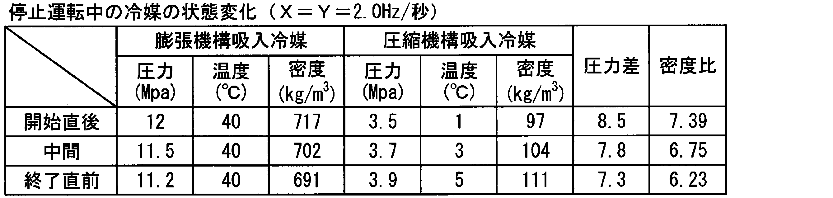
- FIG. 2 is a Mollier diagram showing the refrigeration cycle during the stop operation in the first embodiment.
- the refrigeration cycle a in FIG. 2 represents immediately after the start of the stop operation
- the refrigeration cycle b represents the middle
- the refrigeration cycle c represents immediately before the end. Also, points A, A ′, A ′′ in FIG.
- the control device 6 reduces the rotational speed of the second electric motor 22 at a lower speed than the rotational speed of the first electric motor 12.
- a braking time Tf for stopping the first motor 12 and the second motor 22 is set in advance, and this braking time Tf is stored in the memory of the control device 6.
- the braking time Tf is, for example, 1 minute. Then, the control device 6 completely stops the first electric motor 12 and the second electric motor 22 simultaneously based on the braking time Tf.
- the control device 6 waits until a stop signal is received (NO in step S1), and when the stop signal is received (YES in step S1), the decrease speed X for the first motor and the decrease for the second motor.
- the speed Y is determined (step S2).
- the decrease rate Y is larger than the decrease rate X.
- the decrease rate X for the first motor is 1 Hz / second
- the decrease rate Y for the second motor is 2 Hz / second.
- a table in which the rotation speed at the start of the stop operation and the decrease speed are associated with each other is stored in advance in the memory of the control device 6, and the control device 6 receives the stop signal when the control device 6 receives the stop signal.
- the reduction speeds X and Y may be determined by reading the reduction speed corresponding to the rotational speed of 22 from the memory. Alternatively, it is set in advance how many percent the rotational speed is to be decreased in the stop operation, and the speeds X and Y are determined by dividing the rotational speed when the stop signal is received by the ratio and dividing by the braking time Tf. May be.
- the control device 6 reduces the rotation speed of the first electric motor 12 at the decrease speed X and decreases the rotation speed of the second electric motor 22 at the decrease speed Y. Then, the control device 6 continues to decrease the rotational speed until the elapsed time T after receiving the stop signal becomes equal to or longer than the braking time Tf stored in the memory (NO in step S4), and the elapsed time T is braked. When the time Tf is exceeded (YES in step S4), the first electric motor 12 and the second electric motor 22 are completely stopped (step S5).
- the displacement amount of the expansion mechanism 13 gradually becomes insufficient by making the decrease rate Y of the rotation speed of the second electric motor 12 larger than the decrease speed X of the rotation speed of the first electric motor 12. Can make up for. Therefore, the pressure difference between the high pressure and the low pressure in the refrigeration cycle can be quickly reduced, and energy saving in the stop operation can be achieved.
- the above effect can be obtained with a simple configuration.
- the decrease rate Y is preferably 1.5 times or more, and more than 2.0 times the decrease rate X. Is more preferable. If it has become like this, the time concerning stop operation can be shortened, and the reliability of the 1st compressor 1 and the 2nd compressor 2 can be improved. Moreover, from the viewpoint of improving the stability of temperature and pressure in the refrigeration cycle apparatus, the rate of decrease Y is preferably 2.5 Hz / second or less, and more preferably 2.0 Hz / second or less.
- FIG. 5 shows a refrigeration cycle apparatus 100B according to a second embodiment of the present invention.
- the same components as those in the first embodiment are denoted by the same reference numerals, and the description thereof is omitted. This also applies to third to sixth embodiments described later.
- the refrigeration cycle apparatus 100B of the present embodiment includes a pre-expansion temperature sensor 82 that detects the temperature of the refrigerant flowing through the second pipe 3b, a high-pressure side pressure sensor 72 that detects the pressure of the refrigerant flowing through the second pipe 3b, A pre-compression temperature sensor 81 that detects the temperature of the refrigerant flowing through the four pipes 3d and a low-pressure sensor 71 that detects the pressure of the refrigerant flowing through the fourth pipe 3d are provided.
- the high-pressure side pressure sensor 72 is provided in the second pipe 3b
- the low-pressure side pressure sensor 71 is provided in the branch pipe on the first compression mechanism 11 side of the fourth pipe 3d.
- the main pipe of the first pipe 3a may be provided, and the low pressure side pressure sensor 71 may be provided on the branch pipe or the main pipe or the third pipe 3c on the second compression mechanism 21 side of the fourth pipe 3d.
- the control device 6 uses the temperature and pressure detected by the pre-expansion temperature sensor 82 and the high-pressure side pressure sensor 72, and the pre-compression temperature sensor 81 and the low-pressure side temperature sensor 71 to expand the refrigerant sucked into the expansion mechanism. Then, the density ratio of the refrigerant sucked by the compression mechanism is calculated, and the rate of decrease X for the first motor and the rate of decrease Y for the second motor are determined from the calculated density ratio.
- the control device 6 performs steps S11 to S14 instead of step S2 shown in FIG. That is, when receiving a stop signal (YES in step S1), the control device 6 detects the temperature and pressure of the expansion mechanism suction refrigerant with the pre-expansion temperature sensor 82 and the high-pressure side pressure sensor 72, and the pre-compression temperature sensor 81. Further, the temperature and pressure of the refrigerant sucked by the compression mechanism are detected by the low pressure side temperature sensor 71 (step S11). Next, the control device 6 calculates the density ratio between the expansion mechanism intake refrigerant and the compression mechanism intake refrigerant from the detected temperature and pressure (step S12).
- the control device 6 calculates the target rotational speed H of the second electric motor 22 based on the calculated density ratio, and determines the decrease speed Y for the second electric motor (step S13).
- the target rotational speed H is a rotational speed that determines how far the rotational speed of the second electric motor 22 is reduced in the stop operation before the second electric motor 22 is completely stopped.
- the target rotational speed H is stored in the controller 6 in advance so that the pressure difference between the high pressure and the low pressure is sufficiently small for each predetermined density ratio, and step S12 is performed. What is necessary is just to obtain
- the first motor 12 and the second motor 22 are completely stopped after the braking time Tf has elapsed since the stop signal was received (step S4).
- the decrease speed X for the first motor is determined to be smaller than the decrease speed Y (step S14).
- the decrease speed X may be calculated by subtracting a preset speed difference from the decrease speed Y.
- control device 6 After determining the decrease speeds X and Y, the control device 6 performs steps S3 to S5 as in the first embodiment.
- the density ratio between the expansion mechanism suction refrigerant and the compression mechanism suction refrigerant is calculated, and the decrease speed X for the first motor and the decrease speed Y for the second motor are calculated from the calculated density ratio. Since it is determined, it is possible to perform an appropriate stop operation based on the density ratio during the steady operation, and to further save energy.
- the reduction speed Y is determined using the target rotational speed H of the second electric motor 22 (step S13).
- the braking time Tf is used.
- the refrigeration cycle apparatus of the present embodiment has the same configuration as the refrigeration cycle apparatus 100A of the first embodiment shown in FIG.
- a first braking time Tf for stopping the first motor 12 and a second braking time Tp for stopping the second motor 22 are set in advance, and these braking times Tf, Tp are set in advance. Is stored in the memory of the control device 6.
- the second braking time Tp is set shorter than the first braking time Tf.
- the first braking time Tf is, for example, 1 minute
- the second braking time Tp is, for example, 30 seconds.
- the control device 6 performs the same control as in the first embodiment until step S3, and the second braking time in which the elapsed time T after receiving the stop signal is stored in the memory.
- the rotation speeds of the first motor 12 and the second motor 22 continue to decrease until the time becomes Tp or longer (NO in step S21), and when the elapsed time T becomes equal to or longer than the second braking time Tp (YES in step S21). Then, the second electric motor 22 is completely stopped (step S22).
- control device 6 continues to decrease the rotational speed of the first electric motor 12 until the elapsed time T after receiving the stop signal becomes equal to or longer than the first braking time Tf stored in the memory (step S23).
- the elapsed time T becomes equal to or longer than the first braking time Tf (YES in step S23)
- the first electric motor 12 is completely stopped (step S24).
- the expansion mechanism intake refrigerant and the compression mechanism intake refrigerant are detected from the temperature and pressure detected by these sensors. It is also possible to calculate the density ratio and determine the reduction speed X for the first electric motor and the reduction speed Y for the second electric motor from the calculated density ratio. For example, when steps S11 to S14 shown in FIG. 6 are adopted instead of step S2, the number of revolutions obtained by subtracting the target number of revolutions H from the number of revolutions when receiving the stop signal is divided by the second braking time Tp. What is necessary is just to determine the fall speed Y for 2nd electric motors.
- FIG. 9 shows a refrigeration cycle apparatus 100C according to a fourth embodiment of the present invention.
- the refrigeration cycle apparatus 100B of the present embodiment is provided with an evaporation temperature sensor 83 that detects the evaporation temperature Te of the refrigerant in the evaporator 5. Then, the control device 6 completely stops the first electric motor 12 and the second electric motor 22 simultaneously based on the evaporation temperature Te detected by the evaporation temperature sensor 83.
- the control device 6 performs the same control as in the first embodiment until step S3, and then detects the evaporation temperature Te of the refrigerant in the evaporator 5 by the evaporation temperature sensor 83 ( Step S31).
- the set temperature TE is stored in the memory of the control device 6 in advance, and the control device 6 determines the rotation speeds of the first motor 12 and the second motor 22 until the detected evaporation temperature Te becomes equal to or higher than the set temperature TE.
- the decrease continues (NO in step S32), and when the detected evaporation temperature Te becomes equal to or higher than the set temperature TE (YES in step S32), the first motor 12 and the second motor 22 are completely stopped (step) S5).
- the expansion mechanism intake refrigerant and the compression mechanism intake refrigerant are detected from the temperature and pressure detected by these sensors. It is also possible to calculate the density ratio and determine the reduction speed X for the first electric motor and the reduction speed Y for the second electric motor from the calculated density ratio.
- the second motor 22 can be completely stopped before the first motor 12 as in the third embodiment. is there.
- the refrigeration cycle apparatus of the present embodiment is obtained by adding the high-pressure side pressure sensor 72 shown in FIG. 5 to the refrigeration cycle apparatus 100A of the first embodiment shown in FIG. Then, the control device 6 completely stops the first electric motor 12 and the second electric motor 22 simultaneously based on the pressure Pd detected by the high-pressure sensor 72.
- the control device 6 performs the same control as in the first embodiment until step S3, and then detects the pressure Pd of the expansion mechanism suction refrigerant with the high-pressure side pressure sensor 72 (step S41). ).
- the set pressure PD is stored in the memory of the control device 6 in advance, and the control device 6 reduces the rotation speeds of the first motor 12 and the second motor 22 until the detected pressure Pd becomes equal to or lower than the set pressure PD. (NO in step S42), and when the detected pressure Pd becomes equal to or lower than the set pressure PD (YES in step S42), the first electric motor 12 and the second electric motor 22 are completely stopped (step S5). .
- the first electric motor 12 and the second electric motor 22 can be stopped after the pressure difference between the expansion mechanism intake refrigerant and the compression mechanism intake refrigerant is reliably reduced. Thereby, the reliability of the 1st compressor 1 and the 2nd compressor 2 can be improved.
- the expansion mechanism is detected from the temperature and pressure detected by these sensors. It is also possible to calculate the density ratio between the suction refrigerant and the compression mechanism suction refrigerant, and to determine the lowering speed X for the first motor and the lowering speed Y for the second motor from the calculated density ratio.
- the second motor 22 can be completely stopped prior to the first motor 12 as in the third embodiment. is there.
- the refrigeration cycle apparatus of the present embodiment is obtained by adding the pre-compression temperature sensor 81 shown in FIG. 5 to the refrigeration cycle apparatus 100C of the fourth embodiment shown in FIG. Then, the control device 6 determines the first motor 12 and the second motor 22 based on the temperature difference ⁇ T between the temperature Ts detected by the pre-compression temperature sensor 81 and the temperature Te detected by the evaporation temperature sensor 83, that is, the degree of superheat. Stop at the same time.
- the control device 6 performs the same control as in the first embodiment until step S3, and then detects the temperature Ts of the compression mechanism suction refrigerant by the pre-compression temperature sensor 81 (step S3).
- the evaporating temperature sensor 83 detects the evaporating temperature Te of the refrigerant in the evaporator 5 (step S52).
- the set superheat degree SH is stored in the memory of the control device 6 in advance, and the control device 6 rotates the first electric motor 12 and the second electric motor 22 until the calculated temperature difference ⁇ T becomes equal to or less than the set superheat degree SH.
- the number continues to decrease (NO in step S54), and when the calculated temperature difference ⁇ T becomes equal to or less than the set superheat degree SH (YES in step S54), the first motor 12 and the second motor 22 are completely stopped. (Step S5).
- the first electric motor 12 and the second electric motor 22 can be stopped before the first compression mechanism 11 performs liquid compression. Thereby, the reliability of the 1st compressor 1 and the 2nd compressor 2 can be improved.
- the expansion mechanism is determined from the temperature and pressure detected by these sensors. It is also possible to calculate the density ratio between the suction refrigerant and the compression mechanism suction refrigerant, and to determine the lowering speed X for the first motor and the lowering speed Y for the second motor from the calculated density ratio.
- the second motor 22 can be completely stopped before the first motor 12 as in the third embodiment. It is.
- the refrigeration cycle apparatus of the present invention can be used for various applications such as bathroom drying and snow melting.
Landscapes
- Engineering & Computer Science (AREA)
- Physics & Mathematics (AREA)
- Mechanical Engineering (AREA)
- Thermal Sciences (AREA)
- General Engineering & Computer Science (AREA)
- Control Of Positive-Displacement Pumps (AREA)
Abstract
Description
図1は、本発明の第1実施形態に係る冷凍サイクル装置100Aを示している。この冷凍サイクル装置100Aは、冷媒を循環させる冷媒回路3を備えている。冷媒回路3は、第1圧縮機(膨張機一体型圧縮機)1、第2圧縮機2、放熱器4、蒸発器5、およびこれらの機器を接続する第1~第4配管3a~3dで構成されている。

次に、図5に本発明の第2実施形態に係る冷凍サイクル装置100Bを示す。本実施形態では、第1実施形態と同一構成部分(フローチャート中のステップも含む)には同一符号を付して、その説明を省略する。この点は、後述する第3~第6実施形態においても同様である。

次に、本発明の第3実施形態を説明する。本実施形態の冷凍サイクル装置は、図1に示す第1実施形態の冷凍サイクル装置100Aと同じ構成であるため、その構成図は省略する。
次に、図9に本発明の第4実施形態に係る冷凍サイクル装置100Cを示す。本実施形態の冷凍サイクル装置100Bには、蒸発器5での冷媒の蒸発温度Teを検出する蒸発温度センサ83が設けられている。そして、制御装置6は、蒸発温度センサ83で検出される蒸発温度Teに基づいて、第1電動機12と第2電動機22を同時に完全に停止する。
次に、本発明の第5実施形態を説明する。本実施形態の冷凍サイクル装置は、図1に示す第1実施形態の冷凍サイクル装置100Aに、図5に示す高圧側圧力センサ72を加えたものであるため、その構成図は省略する。そして、制御装置6は、高圧側圧力センサ72で検出される圧力Pdに基づいて、第1電動機12と第2電動機22を同時に完全に停止する。
次に、本発明の第5実施形態を説明する。本実施形態の冷凍サイクル装置は、図9に示す第4実施形態の冷凍サイクル装置100Cに、図5に示す圧縮前温度センサ81を加えたものであるため、その構成図は省略する。そして、制御装置6は、圧縮前温度センサ81で検出される温度Tsと蒸発温度センサ83で検出される温度Teの温度差ΔT、すなわち過熱度に基づいて、第1電動機12と第2電動機22を同時に完全に停止する。
Claims (12)
- 冷媒を圧縮する第1圧縮機構、膨張する冷媒から動力を回収する膨張機構、ならびにシャフトにより前記第1圧縮機構および前記膨張機構と連結された第1電動機を含む第1圧縮機と、
冷媒を圧縮する第2圧縮機構であって冷媒回路中で前記第1圧縮機構と並列に接続される第2圧縮機構、およびシャフトにより前記第2圧縮機構と連結された第2電動機を含む第2圧縮機と、
前記第1圧縮機構および前記第2圧縮機構から吐出される冷媒を放熱させる放熱器と、
前記膨張機構から吐出される冷媒を蒸発させる蒸発器と、
前記第1電動機および前記第2電動機の回転数を低下させながら前記第1電動機および前記第2電動機を停止させる停止運転において、前記第2電動機の回転数を、前記第1電動機の回転数よりも大きな低下速度で低下させる制御装置と、
を備える、冷凍サイクル装置。 - 前記制御装置は、停止信号を受けたときに、前記第1電動機用の低下速度と前記第2電動機用の低下速度を決定し、決定した低下速度で前記第1電動機の回転数および前記第2電動機の回転数を低下させる、請求項1に記載の冷凍サイクル装置。
- 前記第1圧縮機構および前記第2圧縮機構から前記放熱器に冷媒を導く第1配管と、
前記放熱器から前記膨張機構に冷媒を導く第2配管と、
前記膨張機構から前記蒸発器に冷媒を導く第3配管と、
前記蒸発器から前記第1圧縮機構および前記第2圧縮機構に冷媒を導く第4配管と、をさらに備える、請求項2に記載の冷凍サイクル装置。 - 前記第2配管を流れる冷媒の温度を検出する膨張前温度センサと、
前記第2配管または前記第1配管を流れる冷媒の圧力を検出する高圧側圧力センサと、
前記第4配管を流れる冷媒の温度を検出する圧縮前温度センサと、
前記第4配管または前記第3配管を流れる冷媒の圧力を検出する低圧側圧力センサと、をさらに備え、
前記制御装置は、停止信号を受けたときに、前記膨張前温度センサおよび前記高圧側圧力センサならびに前記圧縮前温度センサおよび前記低圧側圧力センサで検出される温度および圧力から前記第2配管を流れる冷媒と前記第4配管を流れる冷媒の密度比を算出し、算出した密度比から前記第1電動機用の低下速度と前記第2電動機用の低下速度を決定する、請求項3に記載の冷凍サイクル装置。 - 前記制御装置は、予め設定された制動時間に基づいて、前記第1電動機および前記第2電動機を完全に停止する、請求項1~4のいずれか一項に記載の冷凍サイクル装置。
- 前記蒸発器での冷媒の蒸発温度を検出する蒸発温度センサをさらに備え、
前記制御装置は、前記蒸発温度センサで検出される蒸発温度に基づいて、前記第1電動機および前記第2電動機を完全に停止する、請求項1~4のいずれか一項に記載の冷凍サイクル装置。 - 前記第1配管または前記第2配管を流れる冷媒の圧力を検出する高圧側圧力センサをさらに備え、
前記制御装置は、前記高圧側圧力センサで検出される圧力に基づいて、前記第1電動機および前記第2電動機を完全に停止する、請求項3に記載の冷凍サイクル装置。 - 前記制御装置は、前記高圧側圧力センサで検出される圧力に基づいて、前記第1電動機
および前記第2電動機を完全に停止する、請求項4に記載の冷凍サイクル装置。 - 前記第4配管を流れる冷媒の温度を検出する圧縮前温度センサと、
前記蒸発器での冷媒の蒸発温度を検出する蒸発温度センサと、をさらに備え、
前記制御装置は、前記圧縮前温度センサで検出される温度と前記蒸発温度センサで検出される温度との温度差に基づいて、前記第1電動機および前記第2電動機を完全に停止する、請求項3に記載の冷凍サイクル装置。 - 前記蒸発器での冷媒の蒸発温度を検出する蒸発温度センサをさらに備え、
前記制御装置は、前記圧縮前温度センサで検出される温度と前記蒸発温度センサで検出される温度との温度差に基づいて、前記第1電動機および前記第2電動機を完全に停止する、請求項4に記載の冷凍サイクル装置。 - 前記制御装置は、前記第1電動機と前記第2電動機を同時に完全に停止する、請求項5~10のいずれか一項に記載の冷凍サイクル装置。
- 前記制御装置は、前記第1電動機よりも先に前記第2電動機を完全に停止する、請求項5~10のいずれか一項に記載の冷凍サイクル装置。
Priority Applications (4)
| Application Number | Priority Date | Filing Date | Title |
|---|---|---|---|
| JP2011518218A JP5208275B2 (ja) | 2009-06-12 | 2010-03-25 | 冷凍サイクル装置 |
| US13/146,854 US20110283723A1 (en) | 2009-06-12 | 2010-03-25 | Refrigeration cycle apparatus |
| EP10785875A EP2442050A1 (en) | 2009-06-12 | 2010-03-25 | Refrigeration cycle device |
| CN2010800057796A CN102301190A (zh) | 2009-06-12 | 2010-03-25 | 制冷循环装置 |
Applications Claiming Priority (2)
| Application Number | Priority Date | Filing Date | Title |
|---|---|---|---|
| JP2009-140820 | 2009-06-12 | ||
| JP2009140820 | 2009-06-12 |
Publications (1)
| Publication Number | Publication Date |
|---|---|
| WO2010143343A1 true WO2010143343A1 (ja) | 2010-12-16 |
Family
ID=43308606
Family Applications (1)
| Application Number | Title | Priority Date | Filing Date |
|---|---|---|---|
| PCT/JP2010/002137 WO2010143343A1 (ja) | 2009-06-12 | 2010-03-25 | 冷凍サイクル装置 |
Country Status (5)
| Country | Link |
|---|---|
| US (1) | US20110283723A1 (ja) |
| EP (1) | EP2442050A1 (ja) |
| JP (1) | JP5208275B2 (ja) |
| CN (1) | CN102301190A (ja) |
| WO (1) | WO2010143343A1 (ja) |
Cited By (3)
| Publication number | Priority date | Publication date | Assignee | Title |
|---|---|---|---|---|
| CN102809235A (zh) * | 2011-05-30 | 2012-12-05 | 株式会社电装 | 多段压缩式制冷循环装置 |
| JP2019533792A (ja) * | 2016-04-07 | 2019-11-21 | エリー クフーリー アスワド,エミリー | 冷却システムの制御および保護デバイス |
| WO2022118730A1 (ja) * | 2020-12-01 | 2022-06-09 | 株式会社前川製作所 | 冷凍システム |
Families Citing this family (10)
| Publication number | Priority date | Publication date | Assignee | Title |
|---|---|---|---|---|
| JP2011214779A (ja) * | 2010-03-31 | 2011-10-27 | Daikin Industries Ltd | 冷凍装置 |
| EP3023713A1 (en) * | 2014-11-19 | 2016-05-25 | Danfoss A/S | A method for controlling a vapour compression system with an ejector |
| FR3029275B1 (fr) * | 2014-11-27 | 2019-03-22 | Valeo Systemes Thermiques | Circuit de climatisation de vehicule automobile |
| RU2680447C1 (ru) | 2015-08-14 | 2019-02-21 | Данфосс А/С | Паровая компрессионная система с по меньшей мере двумя испарительными установками |
| WO2017047354A1 (ja) * | 2015-09-15 | 2017-03-23 | 株式会社デンソー | 複数段圧縮式冷凍サイクル装置 |
| CN108139132B (zh) | 2015-10-20 | 2020-08-25 | 丹佛斯有限公司 | 用于控制有可变接收器压力设定点的蒸气压缩系统的方法 |
| JP6788007B2 (ja) | 2015-10-20 | 2020-11-18 | ダンフォス アクチ−セルスカブ | 長時間エジェクタモードで蒸気圧縮システムを制御するための方法 |
| US20170174049A1 (en) * | 2015-12-21 | 2017-06-22 | Ford Global Technologies, Llc | Dynamically controlled vapor compression cooling system with centrifugal compressor |
| DK180146B1 (en) | 2018-10-15 | 2020-06-25 | Danfoss As Intellectual Property | Heat exchanger plate with strenghened diagonal area |
| WO2024076737A1 (en) * | 2022-10-07 | 2024-04-11 | Energy Recovery, Inc. | Datacenter cooling systems that include pressure exchangers |
Citations (7)
| Publication number | Priority date | Publication date | Assignee | Title |
|---|---|---|---|---|
| JPS5899635A (ja) | 1981-12-10 | 1983-06-14 | Sharp Corp | 空気調和機の制御回路 |
| JP2002257424A (ja) * | 2001-02-26 | 2002-09-11 | Lg Electronics Inc | 空調装置及び空調方法 |
| JP2003302112A (ja) * | 2002-04-08 | 2003-10-24 | Daikin Ind Ltd | 冷凍装置 |
| JP2004020179A (ja) * | 2002-06-14 | 2004-01-22 | Samsung Electronics Co Ltd | 空気調和装置及びその制御方法 |
| JP2004212006A (ja) | 2003-01-08 | 2004-07-29 | Daikin Ind Ltd | 冷凍装置 |
| JP2005055167A (ja) * | 2003-07-23 | 2005-03-03 | Sanden Corp | 空調装置 |
| WO2009047898A1 (ja) * | 2007-10-09 | 2009-04-16 | Panasonic Corporation | 冷凍サイクル装置 |
Family Cites Families (10)
| Publication number | Priority date | Publication date | Assignee | Title |
|---|---|---|---|---|
| JPH0327249Y2 (ja) * | 1984-10-26 | 1991-06-12 | ||
| JP3287608B2 (ja) * | 1992-07-15 | 2002-06-04 | キヤノン株式会社 | シート搬送装置 |
| JP3480752B2 (ja) * | 1994-12-08 | 2003-12-22 | 東芝デジタルメディアエンジニアリング株式会社 | 冷凍サイクル装置 |
| JP3861410B2 (ja) * | 1997-10-28 | 2006-12-20 | 株式会社デンソー | 車両用空調装置 |
| AUPQ588100A0 (en) * | 2000-02-28 | 2000-03-23 | Orford Refrigeration Pty Ltd | Thermostat controller |
| US6497554B2 (en) * | 2000-12-20 | 2002-12-24 | Carrier Corporation | Fail safe electronic pressure switch for compressor motor |
| US7159409B2 (en) * | 2004-03-01 | 2007-01-09 | Tecumseh Products Company | Method and apparatus for controlling the load placed on a compressor |
| KR100608684B1 (ko) * | 2004-08-20 | 2006-08-08 | 엘지전자 주식회사 | 공기조화기의 솔레노이드 밸브 제어방법 |
| EP2126485B1 (en) * | 2007-02-28 | 2017-11-22 | Carrier Corporation | Refrigerant system and control method |
| JP2008309437A (ja) * | 2007-06-18 | 2008-12-25 | Panasonic Corp | 空気調和機 |
-
2010
- 2010-03-25 US US13/146,854 patent/US20110283723A1/en not_active Abandoned
- 2010-03-25 WO PCT/JP2010/002137 patent/WO2010143343A1/ja active Application Filing
- 2010-03-25 EP EP10785875A patent/EP2442050A1/en not_active Withdrawn
- 2010-03-25 CN CN2010800057796A patent/CN102301190A/zh active Pending
- 2010-03-25 JP JP2011518218A patent/JP5208275B2/ja not_active Expired - Fee Related
Patent Citations (7)
| Publication number | Priority date | Publication date | Assignee | Title |
|---|---|---|---|---|
| JPS5899635A (ja) | 1981-12-10 | 1983-06-14 | Sharp Corp | 空気調和機の制御回路 |
| JP2002257424A (ja) * | 2001-02-26 | 2002-09-11 | Lg Electronics Inc | 空調装置及び空調方法 |
| JP2003302112A (ja) * | 2002-04-08 | 2003-10-24 | Daikin Ind Ltd | 冷凍装置 |
| JP2004020179A (ja) * | 2002-06-14 | 2004-01-22 | Samsung Electronics Co Ltd | 空気調和装置及びその制御方法 |
| JP2004212006A (ja) | 2003-01-08 | 2004-07-29 | Daikin Ind Ltd | 冷凍装置 |
| JP2005055167A (ja) * | 2003-07-23 | 2005-03-03 | Sanden Corp | 空調装置 |
| WO2009047898A1 (ja) * | 2007-10-09 | 2009-04-16 | Panasonic Corporation | 冷凍サイクル装置 |
Cited By (3)
| Publication number | Priority date | Publication date | Assignee | Title |
|---|---|---|---|---|
| CN102809235A (zh) * | 2011-05-30 | 2012-12-05 | 株式会社电装 | 多段压缩式制冷循环装置 |
| JP2019533792A (ja) * | 2016-04-07 | 2019-11-21 | エリー クフーリー アスワド,エミリー | 冷却システムの制御および保護デバイス |
| WO2022118730A1 (ja) * | 2020-12-01 | 2022-06-09 | 株式会社前川製作所 | 冷凍システム |
Also Published As
| Publication number | Publication date |
|---|---|
| EP2442050A1 (en) | 2012-04-18 |
| US20110283723A1 (en) | 2011-11-24 |
| JP5208275B2 (ja) | 2013-06-12 |
| CN102301190A (zh) | 2011-12-28 |
| JPWO2010143343A1 (ja) | 2012-11-22 |
Similar Documents
| Publication | Publication Date | Title |
|---|---|---|
| JP5208275B2 (ja) | 冷凍サイクル装置 | |
| US7509817B2 (en) | Cooling cycle apparatus and method of controlling linear expansion valve of the same | |
| JP5040256B2 (ja) | 冷凍サイクル装置およびその制御方法 | |
| JP3679323B2 (ja) | 冷凍サイクル装置およびその制御方法 | |
| JP5120056B2 (ja) | 冷凍装置 | |
| US20100287964A1 (en) | Refrigerating apparatus | |
| WO2014024837A1 (ja) | 二元冷凍装置 | |
| JP2005249384A (ja) | 冷凍サイクル装置 | |
| WO2017038161A1 (ja) | 冷凍サイクル装置及び冷凍サイクル装置の制御方法 | |
| JPWO2006120922A1 (ja) | 冷凍サイクル装置 | |
| JP2005291622A (ja) | 冷凍サイクル装置およびその制御方法 | |
| JP2011047552A (ja) | 冷凍サイクル装置及び空気調和装置 | |
| JP2006517643A (ja) | 蒸気圧縮システムの超臨界圧力調整 | |
| JP5627416B2 (ja) | 二元冷凍装置 | |
| JP2008241065A (ja) | 冷凍装置及び冷凍装置の油戻し方法 | |
| JP2008232588A (ja) | 空気調和装置 | |
| JP6351409B2 (ja) | 空気調和機 | |
| WO2006112157A1 (ja) | 冷凍サイクル装置及びその運転方法 | |
| JP2003074990A (ja) | 冷凍装置 | |
| JP2016090142A (ja) | 二段圧縮式冷凍サイクル装置及びその制御装置並びに制御方法 | |
| JP2015172452A (ja) | 温水生成装置 | |
| JP2008096072A (ja) | 冷凍サイクル装置 | |
| JP2009002564A (ja) | 冷媒冷却回路 | |
| JP2007147211A (ja) | 冷凍サイクル装置の制御方法およびそれを用いた冷凍サイクル装置 | |
| JP2007147211A5 (ja) |
Legal Events
| Date | Code | Title | Description |
|---|---|---|---|
| WWE | Wipo information: entry into national phase |
Ref document number: 201080005779.6 Country of ref document: CN |
|
| 121 | Ep: the epo has been informed by wipo that ep was designated in this application |
Ref document number: 10785875 Country of ref document: EP Kind code of ref document: A1 |
|
| WWE | Wipo information: entry into national phase |
Ref document number: 13146854 Country of ref document: US |
|
| WWE | Wipo information: entry into national phase |
Ref document number: 2011518218 Country of ref document: JP Ref document number: 2010785875 Country of ref document: EP |
|
| NENP | Non-entry into the national phase |
Ref country code: DE |