WO2010140457A1 - 一方向クラッチ - Google Patents
一方向クラッチ Download PDFInfo
- Publication number
- WO2010140457A1 WO2010140457A1 PCT/JP2010/058202 JP2010058202W WO2010140457A1 WO 2010140457 A1 WO2010140457 A1 WO 2010140457A1 JP 2010058202 W JP2010058202 W JP 2010058202W WO 2010140457 A1 WO2010140457 A1 WO 2010140457A1
- Authority
- WO
- WIPO (PCT)
- Prior art keywords
- roller
- way clutch
- coil spring
- torsion coil
- outer shaft
- Prior art date
- Legal status (The legal status is an assumption and is not a legal conclusion. Google has not performed a legal analysis and makes no representation as to the accuracy of the status listed.)
- Ceased
Links
Images





Classifications
-
- F—MECHANICAL ENGINEERING; LIGHTING; HEATING; WEAPONS; BLASTING
- F16—ENGINEERING ELEMENTS AND UNITS; GENERAL MEASURES FOR PRODUCING AND MAINTAINING EFFECTIVE FUNCTIONING OF MACHINES OR INSTALLATIONS; THERMAL INSULATION IN GENERAL
- F16D—COUPLINGS FOR TRANSMITTING ROTATION; CLUTCHES; BRAKES
- F16D41/00—Freewheels or freewheel clutches
- F16D41/06—Freewheels or freewheel clutches with intermediate wedging coupling members between an inner and an outer surface
- F16D41/064—Freewheels or freewheel clutches with intermediate wedging coupling members between an inner and an outer surface the intermediate members wedging by rolling and having a circular cross-section, e.g. balls
- F16D41/066—Freewheels or freewheel clutches with intermediate wedging coupling members between an inner and an outer surface the intermediate members wedging by rolling and having a circular cross-section, e.g. balls all members having the same size and only one of the two surfaces being cylindrical
Definitions
- the present invention relates to a one-way clutch using an elastic member.
- a conventional one-way clutch includes, for example, an outer shaft, a plurality of rollers, and a plurality of elastic members.
- the outer shaft is disposed on the outer peripheral side of the shaft member, and has an annular main body portion and a plurality of projecting portions projecting radially inward from the main body portion.
- a roller and an elastic member are arranged between the rotation directions of adjacent protrusions. The elastic member presses the roller to one side in the rotational direction (see, for example, Patent Document 1).
- a coil spring is used as an elastic member.
- a cap is necessary to provide a cap at the tip of the coil spring, which increases the number of parts. As a result, it is difficult to reduce the manufacturing cost with the conventional one-way clutch.
- An object of the present invention is to provide a one-way clutch capable of realizing stable operation while reducing manufacturing cost.
- the one-way clutch according to the present invention is provided on a shaft member, and includes an outer shaft, a roller, and a torsion coil spring.
- the outer shaft is disposed on the outer peripheral side of the shaft member.
- the roller is disposed between the shaft member and the outer shaft in the radial direction.
- the torsion coil spring is a member that applies a pressing force to the roller using a torsion spring force, and has a contact portion that contacts the roller in the rotation direction of the shaft member and in the opposite direction.
- a torsion coil spring is used, so that a cap and a guide are not required unlike the case of using a coil spring.
- the structure can be simplified and the manufacturing cost can be reduced.
- FIG. 3 is a partial cross-sectional view of a torsion coil spring and its periphery.
- A), B Single figure of a torsion coil spring (compression state).
- A), (B) Single figure of torsion coil spring (free state).
- the partial top view of a torsion coil spring and its periphery (other embodiment).
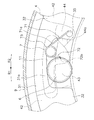
- FIG. 1 is a schematic plan view of the one-way clutch 1.
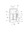
- FIG. 2 is a sectional view of the one-way clutch 1 taken along the line II-II.
- an arrow R1 indicates the rotation direction of the shaft member 2
- an arrow R2 indicates the opposite direction.
- the OO line shown in FIG. 2 is the rotation axis of the shaft member 2.
- a one-way clutch 1 is provided on the outer peripheral side of the shaft member 2 in order to restrict relative rotation in one specific direction between the shaft member 2 and another member (not shown).
- the one-way clutch 1 restricts the rotation of another member (not shown) with respect to the shaft member 2 in the R1 direction (an example of the rotation direction), and the R2 direction (rotation direction) of the other member with respect to the shaft member 2. Rotation in an example of the opposite direction) is allowed.
- the one-way clutch 1 has an outer shaft 3, a plurality of rollers 6, and a plurality of torsion coil springs 7.
- the outer shaft 3 is disposed on the outer peripheral side of the shaft member 2.
- the roller 6 is disposed between the shaft member 2 and the outer shaft 3 in the radial direction.
- the torsion coil spring 7 applies a pressing force to the roller 6 generally in the R1 direction.
- the one-way clutch 1 further has a cover 4 and a plate 9 disposed on the side of the outer shaft 3 in the axial direction. As shown in FIG. 2, the cover 4 is disposed so as to cover the first side surface 3 a of the outer shaft 3. The plate 9 is disposed so as to cover the second side surface 3 b of the outer shaft 3.
- the outer shaft 3 is disposed on the outer peripheral side of the shaft member 2, and other members (not shown) are fixed thereto.
- the outer shaft 3 includes a substantially annular main body 31 disposed on the outer peripheral side of the shaft member 2 and a plurality of protrusions 32 that protrude radially inward from the main body 31.
- the main body 31 has an annular protrusion 31b protruding in the axial direction.
- the cover 4 is fitted on the inner peripheral side of the annular protrusion 31b.
- the annular protrusion 31b positions the cover 4 in the radial direction.
- the protrusions 32 are arranged at substantially equal pitches in the rotation direction of the shaft member 2.
- the cover 4 is fixed to the protrusion 32 by a rivet 34.
- a gap is formed between the protruding portion 32 and the shaft member 2 in the radial direction so that the protruding portion 32 does not contact the outer peripheral surface of the shaft member 2.
- a roller 6 is disposed between the rotation directions of the adjacent protrusions 32 and between the main body 31 and the shaft member 2 in the radial direction.
- the roller 6 is a columnar member for restricting or allowing relative rotation between the shaft member 2 and the outer shaft 3.
- the roller 6 is pressed substantially in the R1 direction by a torsion coil spring 7 supported by the outer shaft 3. It can also be said that the roller 6 is disposed between the shaft member 2 and the outer shaft 3 in the radial direction.
- the outer shaft 3 has a pocket 11 as a space in which the roller 6 is disposed.
- the pocket 11 is formed on the inner side in the radial direction of the main body 31 and between the rotation directions of the adjacent protrusions 32.
- the roller 6 has an annular groove 6a.
- the groove 6 a is disposed in the center of the roller 6 in the axial direction (width direction).
- An end of a torsion coil spring 7 is fitted in the groove 6a (described later).
- the main body 31 has an inclined portion 31a.
- the inclined portion 31a is substantially flat and is inclined so as to approach the shaft member 2 in the R1 direction. For this reason, the radial clearance formed between the inclined portion 31a and the shaft member 2 is gradually reduced in the R1 direction.
- the roller 6 can rotate between the shaft member 2 and the inclined portion 31a.
- the radial clearance is set smaller than the outer diameter of the roller 6 in the R1 side half of the pocket 11, the roller 6 is sandwiched between the shaft member 2 and the inclined portion 31a. The relative rotation of the shaft member 2 and the outer shaft 3 is restricted. In this state, a gap is secured between the rotation direction of the roller 6 and the protruding portion 32 on the R1 side of the roller 6. Since the roller 6 is pressed in the R1 direction by the torsion coil spring 7, when the shaft member 2 rotates in the R1 direction with respect to the outer shaft 3, the roller 6 is likely to be sandwiched between the shaft member 2 and the inclined portion 31a.
- FIG. 3 is a partial plan view of the torsion coil spring 7 and its periphery.
- FIG. 4 is a partial sectional view of the torsion coil spring 7 and its periphery.
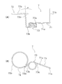
- FIGS. 5A and 5B are single views (compressed state) of the torsion coil spring 7.
- 6 (A) and 6 (B) are single views (free state) of the torsion coil spring 7.
- the one-way clutch 1 is provided with a plurality of torsion coil springs 7 in order to press the roller 6 in the R1 direction.
- the torsion coil spring 7 is composed of a single wire, and comes into contact with the spring main body 73 (an example of an elastic portion), a support portion 71, and the like. Part 72.
- the spring body 73 is a portion wound in a coil shape to generate a torsion spring force. As shown in FIG. 4, in the present embodiment, the spring body 73 is disposed on the side of the outer shaft 3 in the axial direction (on the cover 4 side). The support portion 71 and the contact portion 72 are elastically connected by the spring body 73.
- the support portion 71 is a portion supported by the outer shaft 3, and includes a first support portion 71a and a second support portion 71b. Yes.
- the first support portion 71a is connected to the first end portion 73a of the spring body 73 (more specifically, the end portion disposed on the outer shaft 3 side), and the first support portion 71a is connected to the first end portion 73a of the outer shaft 3 from the first end portion 73a. It extends along one side surface 3a.
- the protrusion 32 of the outer shaft 3 has a support hole 35 penetrating in the axial direction.
- the second support portion 71 b extends in the axial direction from the end portion of the first support portion 71 a and is inserted into the support hole 35. Since the inner diameter of the support hole 35 is larger than the outer diameter of the second support portion 71 b, the second support portion 71 b can rotate within the support hole 35. Thus, the spring body 73 is supported with respect to the outer shaft 3 by the support hole 35 and the support portion 71 of the protrusion 32.
- the contact portion 72 is a portion that transmits a pressing force to the roller 6, and contacts the roller 6 in the R1 direction and the R2 direction.
- the abutting portion 72 includes an intermediate portion 72a and an annular portion 72b.
- the intermediate portion 72a is a portion connected to the second end portion 73b (more specifically, the end portion disposed on the side opposite to the outer shaft 3) of the spring body 73, and is substantially axially extending from the second end portion 73b. It extends to.
- the intermediate portion 72 a in the compressed state in which the torsion coil spring 7 is set, the intermediate portion 72 a extends in the axial direction and is in contact with the outer peripheral surface of the roller 6.
- the intermediate portion 72a is slightly inclined with respect to the axial direction.
- the intermediate portion 72a is inclined with respect to the axial direction so that the spring body 73 is separated from the annular portion 72b. More specifically, as shown in FIG. 6A, the inclination angle of the intermediate portion 72a with respect to the axial direction is an angle ⁇ . Therefore, in the set state shown in FIGS. 5A and 5B, the intermediate portion 72 a and its peripheral portion are elastically deformed by the elastic force generated in the spring body 73, and the intermediate portion 72 a is substantially even on the outer peripheral surface of the roller 6. Abut. The end portion of the intermediate portion 72 a is disposed in the vicinity of the groove 6 a of the roller 6.
- the annular portion 72b is a portion that is formed in a generally annular shape, and is provided at the end of the intermediate portion 72a.
- the annular portion 72b is wound around the roller 6 and disposed in the groove 6a.
- the annular portion 72b extends in an arc from the end of the intermediate portion 72a in the direction in which the roller 6 rotates when the one-way clutch 1 is locked by the roller 6. Since the annular portion 72 b is wound around the roller 6, the elastic force of the torsion coil spring 7 is reliably transmitted to the roller 6. Furthermore, since the annular portion 72b is fitted in the groove 6a, the torsion coil spring 7 is integrated with the roller 6 in the axial direction. It can be said that the torsion coil spring 7 is supported by the roller 6.
- the torsion coil spring 7 may be rotatably supported by the cover 4 or the plate 9.
Landscapes
- Engineering & Computer Science (AREA)
- General Engineering & Computer Science (AREA)
- Mechanical Engineering (AREA)
- Springs (AREA)
- Mechanical Operated Clutches (AREA)
- Seats For Vehicles (AREA)
Abstract
Description
図1および図2を用いて、一実施形態に係る一方向クラッチ1の全体構成について説明する。図1は一方向クラッチ1の平面概略図である。図2は一方向クラッチ1のII-II断面図である。図1において、矢印R1が軸部材2の回転方向を示しており、矢印R2がその反対方向を示している。図2に示すO-O線が軸部材2の回転軸である。
外軸3は、軸部材2の外周側に配置されており、他の部材(図示せず)が固定されている。外軸3は、軸部材2の外周側に配置された概ね環状の本体部31と、本体部31から半径方向内側へ突出する複数の突出部32と、を有している。
図3~図6(B)を用いて、捩りコイルばね7およびその周辺の構成について説明する。図3は捩りコイルばね7およびその周辺の部分平面図である。図4は捩りコイルばね7およびその周辺の部分断面図である。図5(A)および(B)は捩りコイルばね7の単体図(圧縮状態)である。図6(A)および(B)は捩りコイルばね7の単体図(自由状態)である。
図2および図4に示すように、ローラ6および捩りコイルばね7が脱落しないように、外軸3の軸方向側方にはカバー4が配置されている。具体的には、カバー4は、外軸3の第1側面3aを覆うように配置された概ね円板状の部材であり、カバー本体41と、カバー本体41から半径方向外側へ延びる複数の固定部42と、を有している。
図2および図4に示すように、ローラ6が脱落しないように、外軸3の軸方向側方にはプレート9が配置されている。具体的には、プレート9は、外軸3の側面を覆うように外軸3に嵌め込まれた環状の部材であり、円板状のプレート本体91と、筒状部92と、を有している。筒状部92は、プレート本体91の外周部から軸方向に延びており、外軸3の外周部に嵌め込まれている。プレート本体91はカバー4と反対側の外軸3の第2側面3bを覆っている。これにより、ローラ6の脱落を防止できる。
図7を用いて一方向クラッチ1の動作について説明する。図7はローラ6および捩りコイルばね7の動作説明図である。
一方向クラッチ1の特徴は以下の通りである。
本発明の具体的構成は、前述の実施形態に限定されず、本発明の趣旨を逸脱しない範囲において種々の変更および修正が可能である。
2 軸部材
3 外軸
31 本体部
31a 傾斜部
32 突出部
35 支持孔
4 カバー
41 カバー本体
42 固定部
43 カバー部
6 ローラ
7 捩りコイルばね
71 支持部
72 当接部
73 ばね本体(弾性部の一例)
Claims (10)
- 軸部材に設けられた一方向クラッチであって、
前記軸部材の外周側に配置された外軸と、
前記軸部材と前記外軸との半径方向間に配置されたローラと、
捩りばね力を利用して前記ローラに対して押圧力を付与する部材であって、前記軸部材の回転方向およびその反対方向に前記ローラと当接する当接部を有する捩りコイルばねと、
を備えた一方向クラッチ。 - 前記当接部は、前記ローラの外周に沿って円弧状あるいは環状に形成された環状部を有している、
請求項1に記載の一方向クラッチ。 - 前記ローラは、外周面に沿って形成された溝を有しており、
前記環状部は、前記溝内に配置されている、
請求項2に記載の一方向クラッチ。 - 前記溝は、前記ローラにおいて軸方向の中央に配置されている、
請求項3に記載の一方向クラッチ。 - 前記捩りコイルばねは、前記外軸に回転可能に支持されている、
請求項1から4のいずれかに記載の一方向クラッチ。 - 前記外軸は、環状の本体部と、軸方向に延びる支持孔を有し前記本体部から半径方向内側に延びる突出部と、を有しており、
前記捩りコイルばねは、前記当接部と、前記支持孔に挿入された第2端部と、前記当接部および第2端部を弾性的に連結し前記押圧力を発生する弾性部と、を有している、
請求項5に記載の一方向クラッチ。 - 前記弾性部は、前記外軸の軸方向側方に配置されている、
請求項6に記載に一方向クラッチ。 - 前記弾性部は、前記支持孔よりも半径方向外側に配置されている、
請求項6または7に記載の一方向クラッチ。 - 前記外軸の軸方向側方に配置されたカバーをさらに備え、
前記カバーは、前記外軸との軸方向間に前記第2端部を収容するとともに前記第2端部と軸方向に当接可能な規制部を有している、
請求項6から8のいずれかに記載の一方向クラッチ。 - 前記ローラは、軸方向に延びる孔を有しており、
前記当接部は、軸方向に延びる前記孔に挿入されている、
請求項1に記載の一方向クラッチ。
Priority Applications (1)
| Application Number | Priority Date | Filing Date | Title |
|---|---|---|---|
| CN201080022336.8A CN102428288B (zh) | 2009-06-02 | 2010-05-14 | 单向离合器 |
Applications Claiming Priority (2)
| Application Number | Priority Date | Filing Date | Title |
|---|---|---|---|
| JP2009-133351 | 2009-06-02 | ||
| JP2009133351A JP4773546B2 (ja) | 2009-06-02 | 2009-06-02 | 一方向クラッチ |
Publications (1)
| Publication Number | Publication Date |
|---|---|
| WO2010140457A1 true WO2010140457A1 (ja) | 2010-12-09 |
Family
ID=43297594
Family Applications (1)
| Application Number | Title | Priority Date | Filing Date |
|---|---|---|---|
| PCT/JP2010/058202 Ceased WO2010140457A1 (ja) | 2009-06-02 | 2010-05-14 | 一方向クラッチ |
Country Status (3)
| Country | Link |
|---|---|
| JP (1) | JP4773546B2 (ja) |
| CN (1) | CN102428288B (ja) |
| WO (1) | WO2010140457A1 (ja) |
Cited By (1)
| Publication number | Priority date | Publication date | Assignee | Title |
|---|---|---|---|---|
| US10132368B2 (en) | 2013-11-08 | 2018-11-20 | Nsk-Warner K.K. | Roller-type one-way clutch and side plate |
Families Citing this family (3)
| Publication number | Priority date | Publication date | Assignee | Title |
|---|---|---|---|---|
| CN104279248B (zh) * | 2014-10-23 | 2016-08-24 | 重庆从仁机电有限公司 | 一种单向超越离合器 |
| JP6323397B2 (ja) * | 2015-06-02 | 2018-05-16 | トヨタ自動車株式会社 | ワンウェイクラッチの取り付け構造 |
| JP6987612B2 (ja) * | 2017-11-16 | 2022-01-05 | 株式会社シマノ | 釣り用リールのローラクラッチ |
Citations (3)
| Publication number | Priority date | Publication date | Assignee | Title |
|---|---|---|---|---|
| JPS4929345U (ja) * | 1972-03-15 | 1974-03-13 | ||
| JPS53146850U (ja) * | 1977-04-25 | 1978-11-18 | ||
| JP2001323952A (ja) * | 2000-05-16 | 2001-11-22 | Nsk Warner Kk | ラチェット型ワンウェイクラッチ |
Family Cites Families (4)
| Publication number | Priority date | Publication date | Assignee | Title |
|---|---|---|---|---|
| JPS5132658B2 (ja) * | 1972-07-17 | 1976-09-14 | ||
| JPS53146850A (en) * | 1977-08-29 | 1978-12-21 | Janome Sewing Machine Co Ltd | Sewing machine pattern selection controller |
| JP2001234949A (ja) * | 2000-02-22 | 2001-08-31 | Ntn Corp | 一方向クラッチ |
| JP4182091B2 (ja) * | 2005-08-05 | 2008-11-19 | 株式会社エクセディ | 一方向クラッチ |
-
2009
- 2009-06-02 JP JP2009133351A patent/JP4773546B2/ja not_active Expired - Fee Related
-
2010
- 2010-05-14 CN CN201080022336.8A patent/CN102428288B/zh not_active Expired - Fee Related
- 2010-05-14 WO PCT/JP2010/058202 patent/WO2010140457A1/ja not_active Ceased
Patent Citations (3)
| Publication number | Priority date | Publication date | Assignee | Title |
|---|---|---|---|---|
| JPS4929345U (ja) * | 1972-03-15 | 1974-03-13 | ||
| JPS53146850U (ja) * | 1977-04-25 | 1978-11-18 | ||
| JP2001323952A (ja) * | 2000-05-16 | 2001-11-22 | Nsk Warner Kk | ラチェット型ワンウェイクラッチ |
Cited By (1)
| Publication number | Priority date | Publication date | Assignee | Title |
|---|---|---|---|---|
| US10132368B2 (en) | 2013-11-08 | 2018-11-20 | Nsk-Warner K.K. | Roller-type one-way clutch and side plate |
Also Published As
| Publication number | Publication date |
|---|---|
| CN102428288B (zh) | 2014-09-24 |
| JP4773546B2 (ja) | 2011-09-14 |
| CN102428288A (zh) | 2012-04-25 |
| JP2010281346A (ja) | 2010-12-16 |
Similar Documents
| Publication | Publication Date | Title |
|---|---|---|
| US8172055B2 (en) | One-way clutch | |
| JP4943915B2 (ja) | 一方向クラッチ | |
| JP5008539B2 (ja) | 一方向クラッチ | |
| JP4773546B2 (ja) | 一方向クラッチ | |
| CN102119285A (zh) | 单向离合器的保持器 | |
| JP2007113634A (ja) | プーリ構造体 | |
| JP5008538B2 (ja) | 一方向クラッチ | |
| JP4659086B2 (ja) | 一方向クラッチ | |
| WO2015122399A1 (ja) | 逆入力防止クラッチ | |
| JP2017180643A (ja) | 逆入力防止クラッチ | |
| JP3989702B2 (ja) | 一方向クラッチ | |
| JP5555786B1 (ja) | 一方向クラッチ | |
| JP4136266B2 (ja) | 一方向クラッチ | |
| JP2023150141A (ja) | ダンパ装置 | |
| JP4182091B2 (ja) | 一方向クラッチ | |
| JP2011149540A (ja) | 保持器アッセンブリおよび一方向クラッチ | |
| CN118815842A (zh) | 啮合离合器 | |
| JP5637779B2 (ja) | トルクリミッタ | |
| JP2015152089A (ja) | 逆入力防止クラッチ | |
| JP4136250B2 (ja) | 一方向クラッチ | |
| JP4638178B2 (ja) | 逆入力遮断一方向クラッチ | |
| CN118088593A (zh) | 离合装置 | |
| JP2012062944A (ja) | クラッチ及びモータ | |
| JPH11173381A (ja) | ダンパー | |
| JP2017141859A (ja) | 逆入力防止クラッチ |
Legal Events
| Date | Code | Title | Description |
|---|---|---|---|
| WWE | Wipo information: entry into national phase |
Ref document number: 201080022336.8 Country of ref document: CN |
|
| 121 | Ep: the epo has been informed by wipo that ep was designated in this application |
Ref document number: 10783241 Country of ref document: EP Kind code of ref document: A1 |
|
| NENP | Non-entry into the national phase |
Ref country code: DE |
|
| WWE | Wipo information: entry into national phase |
Ref document number: 9882/CHENP/2011 Country of ref document: IN |
|
| 122 | Ep: pct application non-entry in european phase |
Ref document number: 10783241 Country of ref document: EP Kind code of ref document: A1 |