WO2010140408A1 - 蓄電池 - Google Patents
蓄電池 Download PDFInfo
- Publication number
- WO2010140408A1 WO2010140408A1 PCT/JP2010/053928 JP2010053928W WO2010140408A1 WO 2010140408 A1 WO2010140408 A1 WO 2010140408A1 JP 2010053928 W JP2010053928 W JP 2010053928W WO 2010140408 A1 WO2010140408 A1 WO 2010140408A1
- Authority
- WO
- WIPO (PCT)
- Prior art keywords
- exhaust
- lid
- partition wall
- lid body
- surrounding
- Prior art date
- Legal status (The legal status is an assumption and is not a legal conclusion. Google has not performed a legal analysis and makes no representation as to the accuracy of the status listed.)
- Ceased
Links
Images


Classifications
-
- H—ELECTRICITY
- H01—ELECTRIC ELEMENTS
- H01M—PROCESSES OR MEANS, e.g. BATTERIES, FOR THE DIRECT CONVERSION OF CHEMICAL ENERGY INTO ELECTRICAL ENERGY
- H01M50/00—Constructional details or processes of manufacture of the non-active parts of electrochemical cells other than fuel cells, e.g. hybrid cells
- H01M50/10—Primary casings; Jackets or wrappings
- H01M50/147—Lids or covers
- H01M50/148—Lids or covers characterised by their shape
-
- H—ELECTRICITY
- H01—ELECTRIC ELEMENTS
- H01M—PROCESSES OR MEANS, e.g. BATTERIES, FOR THE DIRECT CONVERSION OF CHEMICAL ENERGY INTO ELECTRICAL ENERGY
- H01M50/00—Constructional details or processes of manufacture of the non-active parts of electrochemical cells other than fuel cells, e.g. hybrid cells
- H01M50/30—Arrangements for facilitating escape of gases
-
- Y—GENERAL TAGGING OF NEW TECHNOLOGICAL DEVELOPMENTS; GENERAL TAGGING OF CROSS-SECTIONAL TECHNOLOGIES SPANNING OVER SEVERAL SECTIONS OF THE IPC; TECHNICAL SUBJECTS COVERED BY FORMER USPC CROSS-REFERENCE ART COLLECTIONS [XRACs] AND DIGESTS
- Y02—TECHNOLOGIES OR APPLICATIONS FOR MITIGATION OR ADAPTATION AGAINST CLIMATE CHANGE
- Y02E—REDUCTION OF GREENHOUSE GAS [GHG] EMISSIONS, RELATED TO ENERGY GENERATION, TRANSMISSION OR DISTRIBUTION
- Y02E60/00—Enabling technologies; Technologies with a potential or indirect contribution to GHG emissions mitigation
- Y02E60/10—Energy storage using batteries
Definitions
- the present invention relates to a storage battery having an exhaust structure.
- Japanese Patent Application Laid-Open No. 57-143261 discloses an invention in which the electrolyte in the cell chamber is prevented from flowing out of the exhaust tube through the exhaust passage when the storage battery rolls over.
- the inventors of the present application filed an invention for solving this problem, and disclosed in Japanese Patent Application Laid-Open Nos. 2008-117582 and 2008-. Nos. 117583 and 2008-117584.
- the present invention provides an upper surface of a battery case having a plurality of cell chambers, the interior of which is partitioned by a partition wall, each exhaust pipe communicating with each cell chamber, and adjacent exhausts.
- Independent exhaust passages are formed by surrounding partition walls that isolate and surround the cylinders, and an annular partition wall is provided on the upper surface of the cover plate that surrounds each exhaust cylinder and has a notch opening that communicates with the exhaust passage.
- the lid body is formed in an airtight manner, and further, an upper lid is airtightly applied to the upper surface opening of each exhaust passage of the lid body, and the surrounding partition formed on the back surface of the upper lid is combined with the surrounding partition wall of the lid body.
- Independent exhaust passages by the surrounding partition walls correspond to the independent exhaust passages of the lid main body, and each cup-shaped covering portion projecting downward from the back surface of the upper lid projects from the upper surface of the lid plate of the lid main body.
- a gas exhaust port for exhausting the exhaust gas collectively through at least one gas filter common to the air passage is provided, and each exhaust pipe is divided into a first exhaust pipe and a second exhaust pipe, and the upper end of one of the first exhaust pipes is formed.
- the upper end opening surface of the other second exhaust pipe is positioned so as not to face the space of the cup-shaped covering portion.
- the second cutout opening that communicates with the cutout opening of the annular partition on the upper surface of the lid plate of the lid body.
- the storage battery is characterized in that a partition is provided between the upper end opening surface of the exhaust tube.
- the present invention is characterized in that, as described in claim 2, the lid plate of the lid body is provided with an inclined groove on the down slope toward the second exhaust pipe, and the partition is provided across the inclined groove. Lies in storage batteries.
- the electrolyte when the storage battery is inverted, the electrolyte is formed from the cell chambers on the upper lid that faces upward through the second exhaust pipe and the cutout opening of the annular partition wall on the outer periphery thereof. In the process of flowing out into the exhaust passage, the outflow is hindered by the screen, so that the time until the outflowing electrolyte reaches the gas filter is compared with that of a conventional storage battery without screens, as will be clarified later. Can be delayed, resulting in a significant improvement in leakage prevention effect.
- the electrolyte flowing into each exhaust passage when the inverted storage battery is returned to the upright state, the electrolyte flowing into each exhaust passage is all returned to each cell chamber via the inclined groove below the partition. Time can be shortened.
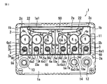
- FIG. 1 is a top view of a lid body of an example storage battery according to the present invention.
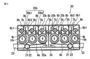
- FIG. 2 is a rear view of the upper lid applied to the upper surface of the lid body.
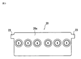
- FIG. 3 is a top view of the upper lid.
- FIG. 4 is a top view in which a part of a storage battery assembled by sequentially applying a lid body and an upper lid to the upper surface of the battery case is removed.
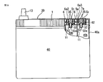
- FIG. 5 is a side view of the storage battery cut along line AA in FIG.
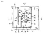
- FIG. 6 is an enlarged top view of the main part of the storage battery.
- FIG. 1 shows a top view of a rectangular box-shaped lid body made of a synthetic resin molding.
- a part of the upper surface of the lid plate 1a of the lid body indicated by reference numeral 1 is formed in a number corresponding to the number of cell chambers formed by partitioning the interior of the battery case in which the lid body 1 is provided by a partition wall.
- a rectangular concave surface 1a1 whose bottom surface is a surface area extending over six cell chambers is formed, and the following exhaust structure is configured in the space of the concave surface.
- a rectangular four-circumference frame 2 having a desired height. Project.
- the height is the same as or higher than the bottom surfaces of the concave grooves 1b and 1b for fitting cylindrical gas discharge ports (described later) formed on the left and right sides of the concave surface 1a1 space.
- the lid plate 1a is located at a position corresponding to six cell chambers in which the interior of the battery case is partitioned in the concave surface 1a1 space surrounded by the four surrounding frames 2. Further, an exhaust hole 3a and a liquid injection port 4 communicating with each cell chamber are formed, and one set of the exhaust cylinder 3 and the liquid injection cylinder 4a protruding from the bottom surface is disposed on the outer periphery of each of the exhaust hole 3a and the liquid injection port 4 respectively.
- Each exhaust cylinder 3 from the upper surface of the cover plate 1a is protruded to an appropriate height higher than the height of the four peripheral frames 2, and each liquid injection cylinder 4a is the same height as the height of the four peripheral frames 2.
- each independent exhaust passage 6a it extends from the side surface of each independent injection cylinder 4a to the side of the exhaust cylinder 3 and extends to the vicinity of one long side frame 2a of the four peripheral frame 2, and A partition wall 7a having the same height as that of the four peripheral frames 2 is provided so that each of the exhaust passages 6a is formed on the exhaust tube 3 side, and an inner passage 6a1 formed in a small chamber surrounding the exhaust passage 6a and the partition wall 7a. It was divided into an outer passage 6a2 communicating with the inner passage 6a1 through a gap 8a existing between the inner side surface of the long side frame 2a.
- a partition wall 9a extending between the exhaust tube 3 and the partition wall 7a from the inner surface of the long side frame 2a and having the same height as the four peripheral frames 2 is provided. This prevents gas that has entered the inner passage 6a1 from each cell chamber in the battery case through the exhaust tube 3 from being directly discharged from the gap 8a to the outer passage 6a2.
- the passage distance is extended so as to be discharged from the gap 8a to the outer passage 6a2, thereby collecting the electrolyte mist. I tried to increase.
- FIG. 2 is a rear view of the upper lid 20 made of a synthetic resin having a size and shape suitable for being applied in contact with the upper surface of the four peripheral frames 2 of the lid main body 1, and FIG.
- the upper lid 20 has a box shape with a concave space formed on the back side.
- the upper lid 20 includes a lid plate 20a and a four-circumferential side wall 20b extending downward from the four peripheral edges to a desired height, and the lower end of the four-circular side wall 20b applies the upper lid 20 to the four peripheral frames 2 of the lid main body 1.
- the outer wall 20b1 is inserted into the gap between the four peripheral frames 2 and the four inner peripheral surfaces of the concave surface 1a1 on the outer side, and the inner four peripheral side walls 20b2 are in contact with the upper ends of the four peripheral frames 2. It forms in the lower end which has the level
- the lid plate 20a has six liquid injection holes formed at positions corresponding to the liquid injection cylinders 4a, 4a,... Of the lid main body 1 when placed on the lid main body 1. Furthermore, independent exhaust passages corresponding to the six independent exhaust passages 6a, 6a,... Provided on the back surface of the lid body 1 are formed in the concave surface 1a1 space on the back surface of the upper lid as follows. More specifically, on the back surface of the cover plate 20a, there are six liquid injection ports 4, 4,... And liquid injection cylinders 4a, 4a,. ..
- liquid injection tubes 4b, 4b,... At the outer periphery of the liquid injection ports 4, 4,...
- the surrounding partition walls 5b, 5b,... are flush with the surrounding wall 20b2 at positions corresponding to the surrounding partition walls 5a, 5a,... Projecting from the upper surface of the lid plate 1a in the four peripheral frames 2 of the lid body 1.
- independent exhaust passages 6b, 6b, ... corresponding to the independent exhaust passages 6a, 6a, ... formed in the lid body 1 are formed.
- the partition wall 7b is disposed at a position corresponding to the partition wall 7a disposed on the lid body 1, the partition wall 9b is disposed at a position corresponding to the partition wall 9a, and the position corresponding to the splash-proof wall 10a attached to the side surface of the partition wall 7a.
- Each of the spray walls 10b is disposed so as to protrude from the back surface of the lid plate 20a to the same height as the four-side wall 20b2, whereby the gap 8a formed in the lid body 1, the inner passage 6a1 formed in the small chamber, and the outer side A gap 8b and an inner passage 6b1 and an outer passage 6b2 formed in a small chamber were formed at positions corresponding to the passage 6a2.
- the six exhaust passages 6a, 6a,... Formed in the lid body 1 and the six exhaust passages 6b, 6b formed in the upper lid 20 are clearly shown in FIGS.
- the three independent exhaust passages 6a, 6a, 6a on the left side of the lid body 1 and the three independent exhaust passages 6b, 6b, 6b on the left side of the upper lid 20 are communicated in the vertical direction.
- Exhaust passages 6, 6, and 6 are formed, and these exhaust passages 6, 6, and 6 communicate with an explosion-proof gas filter 21 provided in a left corner of the four-side wall 20 b on the left side on the upper lid 20 side.
- each of the three right sides of the lid body 1 The standing exhaust passages 6a, 6a, 6a and the three independent exhaust passages 6b, 6b, 6b on the right side of the upper lid 20 are communicated in the vertical direction to form exhaust passages 6, 6, 6;
- These exhaust passages 6, 6, 6 communicate with an explosion-proof gas filter 21 provided in the right corner of the four-side wall 20 b on the right side on the upper lid 20 side. More specifically, as shown in FIG.
- the three independent exhaust passages 6b, 6b, 6b on the upper lid 20 side extend into the left corner of the four-side wall 20b, and the three independent exhaust passages on the right side.
- the passages 6b, 6b, 6b extend into the right corner of the four-side wall 20b, and the left and right exhaust passages 6b, 6b, 6b and 6b, 6b, 6b are defined in the left and right corners, respectively.
- the outer end surfaces of the partition walls 5b, 5b, 5b and 5b, 5b, 5b, 5b at the same level as or lower than the upper ends, that is, at positions closer to the cover plate 20a of the upper cover 20.
- Gas filter mounting cylinders 22 and 22 each equipped with an explosion-proof gas filter 21 are fixed to each other by any means such as press-fitting or adhering to each other, and are located on the side of the respective filter mounting cylinders 22 and 22.
- the gas outlet 23 which communicates with these mounting cylinder 22, 22 provided.
- cylindrical gas exhaust ports 23 and 23 are provided, and the inner ends thereof are opened to communicate with the filter mounting tubes 22 and 22.
- Each of the cylindrical gas exhaust ports 23 and 23 is, for example, a cylinder having a hollow rectangular cross section, and the holes provided in the right and left short side walls of the four-side wall 20b are gas-liquid tightly penetrated and fixed.
- the left and right filter mounting cylinders 22 and 22 have upper surface openings at the outer ends of the left and right exhaust passages, respectively.
- the left and right gas exhaust ports 23 are connected to the lid body at the same time as indicated by circular phantom lines above the space portions 2c, 2c in the left and right corner portions of the four peripheral frames 2 of the lid body 1. It is made to be located in the above-mentioned fitting concave grooves 1b and 1b on the left and right of the upper surface of 1.
- the lower end of the four-sided side wall 1c of the lid body 1 and the partition walls on the back surface thereof are closed by a conventional method so as to close the upper surface opening of the battery case 40 shown in FIGS.
- the upper lid 20 is provided on the upper surface, and the four peripheral frames 2b of the upper lid 20 are fitted on the upper surface of the four peripheral frames 2 of the lid main body 1, and are bonded to each other in a gas-liquid tight manner by heat fusion, adhesion, or the like.
- the surrounding partition walls 5a, 5a,..., 5b, 5b,... are combined by the combination of the four peripheral side walls 20b of the upper lid 20 and the four peripheral frames 2 of the lid body 1.
- the exhaust passages 6a, 6a,... On the lid body 1 side that surround the respective exhaust cylinders 3, 3,. are provided with six independent exhaust passages 6, 6... In which the exhaust passages 6 b, 6 b,... On the upper lid 20 side are communicated in the vertical direction, and in each of the exhaust passages 6, 6,.
- a partition wall 7b, a partition wall 9a, 9a, and a splash barrier wall 10a, 10b are obtained.
- an inner passage and an outer passage formed in a small chamber communicating in the vertical direction.
- the lead acid battery in which the gaps are respectively formed is obtained.
- an electrolytic solution is injected from each of the injection holes 4 and 4 of the upper lid 20 of the storage battery, and the electrode plates (not shown) accommodated in the cell chambers 40b, 40b,.
- the electrolyte solution is held, and a sealing plug (not shown) is applied to each liquid injection port 4 to constitute a lead storage battery.
- the gas generated in each cell chamber of the battery case during charging or overcharging of the lead storage battery enters the respective exhaust passages 6, 6,...
- the gas from three independent exhaust passages 6, 6, 6 on the left side and the right side reaches the front space portions 2 c, 2 c, and then the left and right gas filters 21,
- the gas is exhausted to the outside from the left and right gas discharge ports 23 and 23 via 21.
- the gas passes through each of the independent exhaust passages 6, 6,..., It collides with the various partition walls and splash-proof walls, so that the electrolyte mist in the gas is captured and only the gas is captured. Is discharged to the outside, so that liquid leakage in the exhaust is prevented.
- the collected electrolytes do not mix with each other. In order to flow down the electrolytic solution trapped in each of the independent exhaust passages 6, 6,...
- the storage battery exhaust structure exemplified above is configured as follows so that liquid leakage is prevented even when the storage battery is inverted. That is, the exhaust cylinder 3 communicating with each cell chamber 40 b of the battery case 40 to the lid plate 1 a of the lid body 1 is configured as two exhaust cylinders 31 and 32. In the example shown in FIG. 1 and FIGS.
- the exhaust hole 3a of one exhaust cylinder is divided into two by the partition wall p to form two compact exhaust cylinders 31 and 32.
- one of the two exhaust cylinders 31 and 32 has a length extending from the upper surface of the cover plate 1a, that is, the length extending toward the exhaust passage 6a, that is, a height, and the other one. While the length of the second exhaust cylinder 32, that is, higher than the height, the second exhaust cylinder has a length extending downward from the lower surface of the cover plate 1a of the first exhaust cylinder 31, that is, toward the cell chamber 40b. The length was shorter than 32.
- the exhaust hole 31a of the first exhaust cylinder 31 has a smaller diameter at the upper side opening to the exhaust passage 6a than the lower side opening to the cell chamber 40b side, and the exhaust hole 32a of the second exhaust cylinder 32 is formed from the cell chamber A reverse taper is formed such that the diameter gradually increases from the 40b side toward the exhaust passage 6a side.
- the upper end surfaces of the first and second exhaust pipes 31 and 32 including the partition wall p are formed as inclined surfaces. In this case, the lower end of the upper end opening surface 32a1 of the inclined exhaust hole 32a of the second exhaust cylinder 32 is opened at the same position as the upper surface of the cover plate 1a, and the trapped electrolysis flowing down from the exhaust passage 6 is obtained.
- the liquid can be refluxed into the cell chamber through the exhaust hole 32 a of the second exhaust cylinder 32.
- the annular partition wall 33a and projects from the upper surface of the lid plate 1a the provided with, while allowed to communicate with the inner passage 6a1 of the outer annular space S 1 through the notch port 34 opening upward formed in a portion of the annular partition wall 33a, is formed through the annular space S 1 the notch opening 34 resides exhaust pores 31a of the first and second exhaust pipe 31, and 32a and the annular space S 1, and to be communicated.
- the notch 34 was provided at a position facing the exhaust hole 32a of the second exhaust cylinder.
- the upper lid 20 has the above-described annular partition walls 33a, 33a,. .., Annular ribs 33b, 33b,... Having the same size and shape as the respective annular barriers 33a are projected from the back surface of the upper lid 20.
- each of the partition walls 9a, 9a,... Arranged inwardly extending from the long side frame 2a of the four peripheral frame 2 of the lid body 1 has each of the annular partition walls corresponding to the inner ends thereof. 33a, 33a,...
- the partition walls 9b, 9b are also provided on the back surface of the upper lid 20 so as to extend inwardly from the long side walls 20b1 of the four peripheral side walls 20b.
- ... are formed so as to be combined with the outer peripheral side surfaces of the respective annular partition walls 33b, 33b,.
- the inner passage 6a1 formed in each small chamber of each exhaust passage 6a is formed as a detour passage around the annular partition wall 33a. 1 and FIG. 5, when the notches 34, 34,... Of the respective annular partition walls 33a, 33a,... Are arranged toward the long side walls 2a, 2a,.
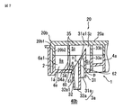
- the upper lid 20 is airtightly applied to the upper surface of the lid body 1, as clearly shown in FIGS. 7 and 8, the lower end of the annular partition wall 33 b depending from the back surface of the upper lid 2 is the lid body 1.
- the upper surface of the annular partition wall 33a extending upward from the upper surface of the upper partition wall 20a is in contact with the upper end of the annular partition wall 33a.
- the annular partition wall hangs down from the cover plate 20a of the upper cover 20 and the rear surface thereof in this contact state.
- a U-shaped cup-like covering portion 35 formed by the 33b first, the annular space S between the cup space S 3 to exist a gap S 2 above the second exhaust pipe 31, 32 in its lower 1 , the upper portions of the first and second exhaust cylinders 31 and 32 are covered, and the height of the upper portion of the first exhaust cylinder 31 faces the cup-shaped covering portion 35.
- the upper opening surface of the second exhaust pipe 32 is formed on the cup-shaped covering portion 35. A height position that does not face the inside between and so allowed to communicate with the exhaust passage through the annular partition wall 34 adjacent.
- the height of the annular partition wall 33a projecting from the lid plate 1a of the lid body 1 on the upper surface, and accordingly, the upper surface opening end 34a of the notch 34 having a rectangular shape with the upper end opened to the annular partition wall 33a. was set at the same height as the lower end of the inclined opening surface of the upper end 31a1 of the exhaust hole 31a of the first exhaust cylinder 31 or a position lower than that.
- the cup-shaped covering portion 35 comprising the lid plate 20a of the upper lid 20 and the annular partition wall 33b that hangs down from this is manufactured as a separate member from the upper lid 20a, and this is fitted into the cup-shaped covering portion provided on the upper lid 20. You may make it equip
- the first exhaust cylinder 31 and the second exhaust cylinder 32 are cylindrical, and the upper end portion thereof is obliquely crossed to form an inclined surface.
- the hole diameter at the lower end of the 31 exhaust holes 31a was 2 mm, and the hole diameter at the upper end was 1 mm.
- the hole diameter at the lower end of the exhaust hole 32a of the second exhaust cylinder 32 is preferably 2.5 mm, and the hole diameter at the upper end is preferably 3 mm.
- the storage battery having the exhaust structure of the above embodiment the six exhaust passages 6, 6,... Are divided into two groups, the gas from the left independent exhaust passages 6, 6, 6 and the right independent exhaust respectively.
- the gas from the passages 6, 6 and 6 is exhausted from the gas discharge ports 23 and 23 through the common explosion-proof filter 21 on the left side and the common explosion-proof gas filter 21 on the left side.
- both ends thereof face the left and right space portions 2c, 2c, and the lid body 1
- a long rectangular mutual communication path 50 is formed below the left and right gas filters 21, 21 disposed on the upper lid 20, while on the inner side of the four peripheral side walls 20 b of the upper lid 20.
- the communication path 50 extends parallel to the four-side wall 20b and is connected to the long side wall 20b1 at both ends thereof. It is a long rectangle between the character-shaped surrounding partition walls 5b and both ends thereof are the left and right space portions 2c, 2c.
- the exhaust structure provided with the mutual communication path 50 can be applied not only to the above-described liquid storage battery but also to a non-liquid storage battery that does not generate a free electrolytic solution in which the electrode plate group is completely impregnated. Needless to say.
- the storage battery of the above-described embodiment the case where the entire exhaust passage is divided into two groups and the communication passage 50 that connects the two filters to each other is formed for the two filters that are arranged in common with each group is shown. Regardless of the number of exhaust passages, all exhaust passages are divided into three or more, and in the case of a storage battery having an exhaust structure having three or more filters arranged for each group, What is necessary is just to provide the communicating path which mutually communicates between the filters.
- the storage battery having the exhaust structure described above will not leak to the outside if it is established in about 10 minutes after handstand, but if it is maintained in such a state for a long time without noticing rollover or handstand.
- the electrode plate exposed by rollover or handstand reacts with the air, the internal pressure fluctuates, the air lock balance is lost, and there is a case of leaking. Therefore, even in such a case, the present invention is to suppress the leakage to the outside through the gas filter for a long time and to improve the effect of preventing the leakage of the electrolyte to the outside.
- FIGS. 6, 7, and 8 the exhausts of the independent exhaust passages 6 a, 6 a,... Disposed on the upper surface of the lid body 1 of the storage battery.
- a partition 60 is provided on the upper surface of the lid plate 1 a of the lid body 1 between the second exhaust cylinder 32 adjacent to the opening 34.
- the electrolyte When the electrolyte is refluxed, not only does it recirculate around the partition 60 but also recirculates through the inclined groove 61, The time to return the whole amount can be shortened. Furthermore, when a plurality of reflux holes 62 are provided in the lid plate 1a along the inner peripheral surface of the annular partition wall 33a, the reflux time can be further shortened.
- the present invention has been described with lead storage batteries in the above embodiments, it can be applied to nickel-cadmium batteries and other storage batteries. Further, in the above embodiment, a box-shaped one is used as the upper lid 20, but instead of this, although not shown, it is a simple lid plate lacking a four-side wall, and its peripheral part is airtight to the four-side frame of the lid body.
- the lid plate is air-tightly bound to the rear surface of each of the surrounding bulkheads in the four peripheral frames of the lid body, and the lid plate is connected via at least one gas filter communicating with each independent exhaust passage. You may form so that it may exhaust collectively from the gas exhaust port drilled in.
- the four peripheral frames 2a of the lid body 1 are provided in the concave space with the upper surface being the concave surface 1a1, but although not shown, the upper surface of the lid body is a flat surface,
- the exhaust structure may be formed so as to protrude upward from the flat surface, and the exhaust structure described above may be configured therein.
- the upper lid is slightly protruded from the lid body, but the upper lid may be flush with the lid body.
Landscapes
- Chemical & Material Sciences (AREA)
- Chemical Kinetics & Catalysis (AREA)
- Electrochemistry (AREA)
- General Chemical & Material Sciences (AREA)
- Gas Exhaust Devices For Batteries (AREA)
Applications Claiming Priority (2)
| Application Number | Priority Date | Filing Date | Title |
|---|---|---|---|
| JP2009-132972 | 2009-06-02 | ||
| JP2009132972A JP5396161B2 (ja) | 2009-06-02 | 2009-06-02 | 蓄電池 |
Publications (1)
| Publication Number | Publication Date |
|---|---|
| WO2010140408A1 true WO2010140408A1 (ja) | 2010-12-09 |
Family
ID=43297549
Family Applications (1)
| Application Number | Title | Priority Date | Filing Date |
|---|---|---|---|
| PCT/JP2010/053928 Ceased WO2010140408A1 (ja) | 2009-06-02 | 2010-03-03 | 蓄電池 |
Country Status (2)
| Country | Link |
|---|---|
| JP (1) | JP5396161B2 (enExample) |
| WO (1) | WO2010140408A1 (enExample) |
Cited By (4)
| Publication number | Priority date | Publication date | Assignee | Title |
|---|---|---|---|---|
| US10135048B2 (en) | 2015-02-27 | 2018-11-20 | GS Yuasa Internationl Ltd. | Lead-acid battery |
| WO2019011458A1 (de) * | 2017-07-10 | 2019-01-17 | FRÖTEK Vermögensverwaltung GmbH | Fluidführender anschlussstecker für eine batterie |
| US10319969B2 (en) | 2015-03-30 | 2019-06-11 | Gs Yuasa International Ltd. | Lead-acid battery and method of manufacturing lid member of lead-acid battery |
| CN110024173A (zh) * | 2017-07-04 | 2019-07-16 | 株式会社Lg化学 | 二次电池 |
Families Citing this family (5)
| Publication number | Priority date | Publication date | Assignee | Title |
|---|---|---|---|---|
| KR101285055B1 (ko) * | 2012-11-29 | 2013-07-10 | 세방전지(주) | 축전지의 내누액 방지 커버 |
| KR101775453B1 (ko) | 2015-07-28 | 2017-09-07 | 세방전지(주) | 내누액성이 향상된 일체형 배터리 커버 |
| JP2017182986A (ja) * | 2016-03-29 | 2017-10-05 | 株式会社Gsユアサ | 鉛蓄電池 |
| JP7000844B2 (ja) | 2017-12-25 | 2022-02-04 | 株式会社Gsユアサ | 鉛蓄電池 |
| KR102295775B1 (ko) * | 2019-07-30 | 2021-08-31 | 한국앤컴퍼니 주식회사 | 미로 누액이동경로를 제공하는 납축전지의 누액방지 구조 |
Citations (4)
| Publication number | Priority date | Publication date | Assignee | Title |
|---|---|---|---|---|
| JPH11233092A (ja) * | 1998-02-19 | 1999-08-27 | Yukio Uemichi | 蓄電池 |
| JP2005166318A (ja) * | 2003-11-28 | 2005-06-23 | Yuasa Corp | 鉛蓄電池 |
| JP2008177042A (ja) * | 2007-01-18 | 2008-07-31 | Furukawa Battery Co Ltd:The | 蓄電池用二重蓋排気構造 |
| JP2009016063A (ja) * | 2007-07-02 | 2009-01-22 | Furukawa Battery Co Ltd:The | 蓄電池 |
-
2009
- 2009-06-02 JP JP2009132972A patent/JP5396161B2/ja active Active
-
2010
- 2010-03-03 WO PCT/JP2010/053928 patent/WO2010140408A1/ja not_active Ceased
Patent Citations (4)
| Publication number | Priority date | Publication date | Assignee | Title |
|---|---|---|---|---|
| JPH11233092A (ja) * | 1998-02-19 | 1999-08-27 | Yukio Uemichi | 蓄電池 |
| JP2005166318A (ja) * | 2003-11-28 | 2005-06-23 | Yuasa Corp | 鉛蓄電池 |
| JP2008177042A (ja) * | 2007-01-18 | 2008-07-31 | Furukawa Battery Co Ltd:The | 蓄電池用二重蓋排気構造 |
| JP2009016063A (ja) * | 2007-07-02 | 2009-01-22 | Furukawa Battery Co Ltd:The | 蓄電池 |
Cited By (6)
| Publication number | Priority date | Publication date | Assignee | Title |
|---|---|---|---|---|
| US10135048B2 (en) | 2015-02-27 | 2018-11-20 | GS Yuasa Internationl Ltd. | Lead-acid battery |
| US10319969B2 (en) | 2015-03-30 | 2019-06-11 | Gs Yuasa International Ltd. | Lead-acid battery and method of manufacturing lid member of lead-acid battery |
| CN110024173A (zh) * | 2017-07-04 | 2019-07-16 | 株式会社Lg化学 | 二次电池 |
| CN110024173B (zh) * | 2017-07-04 | 2022-02-22 | 株式会社Lg化学 | 二次电池 |
| US11374285B2 (en) | 2017-07-04 | 2022-06-28 | Lg Energy Solution, Ltd. | Secondary battery |
| WO2019011458A1 (de) * | 2017-07-10 | 2019-01-17 | FRÖTEK Vermögensverwaltung GmbH | Fluidführender anschlussstecker für eine batterie |
Also Published As
| Publication number | Publication date |
|---|---|
| JP2010282743A (ja) | 2010-12-16 |
| JP5396161B2 (ja) | 2014-01-22 |
Similar Documents
| Publication | Publication Date | Title |
|---|---|---|
| WO2010140408A1 (ja) | 蓄電池 | |
| JP2010282743A5 (enExample) | ||
| JP5760015B2 (ja) | 蓄電池の内漏液防止カバー(batterycoverforpreventionelectrolyteleakage) | |
| US10319969B2 (en) | Lead-acid battery and method of manufacturing lid member of lead-acid battery | |
| US4576879A (en) | Sealed lead acid battery | |
| CN105932341B (zh) | 铅蓄电池 | |
| JP4715089B2 (ja) | 鉛蓄電池 | |
| EP1280214B1 (en) | A leak resistant automotive battery | |
| JP5148862B2 (ja) | 蓄電池の排気構造 | |
| JP4516098B2 (ja) | 蓄電池 | |
| JP2009070628A (ja) | 鉛蓄電池 | |
| JP5183985B2 (ja) | 蓄電池 | |
| JP5148861B2 (ja) | 蓄電池の排気構造 | |
| US20040086778A1 (en) | Exhaust structure of storage battery | |
| JP2010205587A (ja) | 鉛蓄電池 | |
| JP2017182986A (ja) | 鉛蓄電池 | |
| JP5365046B2 (ja) | 鉛蓄電池 | |
| JP2017059419A (ja) | 鉛蓄電池 | |
| JP5095992B2 (ja) | 蓄電池の液漏れ防止装置 | |
| JP4246600B2 (ja) | 蓄電池排気構造 | |
| US20060166081A1 (en) | Battery manifold vent | |
| JP5148863B2 (ja) | 蓄電池の排気構造 | |
| JP4698153B2 (ja) | 蓄電池排気構造 | |
| JP2008177042A (ja) | 蓄電池用二重蓋排気構造 | |
| JP5386773B2 (ja) | 密閉型鉛蓄電池 |
Legal Events
| Date | Code | Title | Description |
|---|---|---|---|
| 121 | Ep: the epo has been informed by wipo that ep was designated in this application |
Ref document number: 10783194 Country of ref document: EP Kind code of ref document: A1 |
|
| NENP | Non-entry into the national phase |
Ref country code: DE |
|
| WWE | Wipo information: entry into national phase |
Ref document number: 2693/MUMNP/2011 Country of ref document: IN |
|
| 122 | Ep: pct application non-entry in european phase |
Ref document number: 10783194 Country of ref document: EP Kind code of ref document: A1 |