WO2010137701A1 - 刃先交換式ドリルおよびドリル本体 - Google Patents
刃先交換式ドリルおよびドリル本体 Download PDFInfo
- Publication number
- WO2010137701A1 WO2010137701A1 PCT/JP2010/059134 JP2010059134W WO2010137701A1 WO 2010137701 A1 WO2010137701 A1 WO 2010137701A1 JP 2010059134 W JP2010059134 W JP 2010059134W WO 2010137701 A1 WO2010137701 A1 WO 2010137701A1
- Authority
- WO
- WIPO (PCT)
- Prior art keywords
- drill
- chip
- wall surface
- forming portion
- drill body
- Prior art date
- Legal status (The legal status is an assumption and is not a legal conclusion. Google has not performed a legal analysis and makes no representation as to the accuracy of the status listed.)
- Ceased
Links
Images




Classifications
-
- C—CHEMISTRY; METALLURGY
- C21—METALLURGY OF IRON
- C21D—MODIFYING THE PHYSICAL STRUCTURE OF FERROUS METALS; GENERAL DEVICES FOR HEAT TREATMENT OF FERROUS OR NON-FERROUS METALS OR ALLOYS; MAKING METAL MALLEABLE, e.g. BY DECARBURISATION OR TEMPERING
- C21D9/00—Heat treatment, e.g. annealing, hardening, quenching or tempering, adapted for particular articles; Furnaces therefor
- C21D9/22—Heat treatment, e.g. annealing, hardening, quenching or tempering, adapted for particular articles; Furnaces therefor for drills; for milling cutters; for machine cutting tools
-
- B—PERFORMING OPERATIONS; TRANSPORTING
- B23—MACHINE TOOLS; METAL-WORKING NOT OTHERWISE PROVIDED FOR
- B23B—TURNING; BORING
- B23B51/00—Tools for drilling machines
-
- B—PERFORMING OPERATIONS; TRANSPORTING
- B23—MACHINE TOOLS; METAL-WORKING NOT OTHERWISE PROVIDED FOR
- B23B—TURNING; BORING
- B23B51/00—Tools for drilling machines
- B23B51/02—Twist drills
-
- B—PERFORMING OPERATIONS; TRANSPORTING
- B23—MACHINE TOOLS; METAL-WORKING NOT OTHERWISE PROVIDED FOR
- B23B—TURNING; BORING
- B23B51/00—Tools for drilling machines
- B23B51/08—Drills combined with tool parts or tools for performing additional working
-
- B—PERFORMING OPERATIONS; TRANSPORTING
- B23—MACHINE TOOLS; METAL-WORKING NOT OTHERWISE PROVIDED FOR
- B23C—MILLING
- B23C5/00—Milling-cutters
- B23C5/16—Milling-cutters characterised by physical features other than shape
- B23C5/20—Milling-cutters characterised by physical features other than shape with removable cutter bits or teeth or cutting inserts
-
- C—CHEMISTRY; METALLURGY
- C21—METALLURGY OF IRON
- C21D—MODIFYING THE PHYSICAL STRUCTURE OF FERROUS METALS; GENERAL DEVICES FOR HEAT TREATMENT OF FERROUS OR NON-FERROUS METALS OR ALLOYS; MAKING METAL MALLEABLE, e.g. BY DECARBURISATION OR TEMPERING
- C21D1/00—General methods or devices for heat treatment, e.g. annealing, hardening, quenching or tempering
- C21D1/06—Surface hardening
- C21D1/09—Surface hardening by direct application of electrical or wave energy; by particle radiation
-
- B—PERFORMING OPERATIONS; TRANSPORTING
- B23—MACHINE TOOLS; METAL-WORKING NOT OTHERWISE PROVIDED FOR
- B23B—TURNING; BORING
- B23B2251/00—Details of tools for drilling machines
- B23B2251/40—Flutes, i.e. chip conveying grooves
- B23B2251/406—Flutes, i.e. chip conveying grooves of special form not otherwise provided for
-
- B—PERFORMING OPERATIONS; TRANSPORTING
- B23—MACHINE TOOLS; METAL-WORKING NOT OTHERWISE PROVIDED FOR
- B23B—TURNING; BORING
- B23B2270/00—Details of turning, boring or drilling machines, processes or tools not otherwise provided for
- B23B2270/30—Chip guiding or removal
-
- Y—GENERAL TAGGING OF NEW TECHNOLOGICAL DEVELOPMENTS; GENERAL TAGGING OF CROSS-SECTIONAL TECHNOLOGIES SPANNING OVER SEVERAL SECTIONS OF THE IPC; TECHNICAL SUBJECTS COVERED BY FORMER USPC CROSS-REFERENCE ART COLLECTIONS [XRACs] AND DIGESTS
- Y02—TECHNOLOGIES OR APPLICATIONS FOR MITIGATION OR ADAPTATION AGAINST CLIMATE CHANGE
- Y02P—CLIMATE CHANGE MITIGATION TECHNOLOGIES IN THE PRODUCTION OR PROCESSING OF GOODS
- Y02P10/00—Technologies related to metal processing
- Y02P10/20—Recycling
-
- Y—GENERAL TAGGING OF NEW TECHNOLOGICAL DEVELOPMENTS; GENERAL TAGGING OF CROSS-SECTIONAL TECHNOLOGIES SPANNING OVER SEVERAL SECTIONS OF THE IPC; TECHNICAL SUBJECTS COVERED BY FORMER USPC CROSS-REFERENCE ART COLLECTIONS [XRACs] AND DIGESTS
- Y10—TECHNICAL SUBJECTS COVERED BY FORMER USPC
- Y10T—TECHNICAL SUBJECTS COVERED BY FORMER US CLASSIFICATION
- Y10T408/00—Cutting by use of rotating axially moving tool
- Y10T408/89—Tool or Tool with support
- Y10T408/892—Tool or Tool with support with work-engaging structure detachable from cutting edge
Definitions
- the present invention relates to a blade-replaceable drill on which a cutting insert is detachably mounted and a drill body of the blade-replaceable drill.
- Patent Document 1 discloses a blade-tip replaceable drill in which a plurality of rows of grooves extending along the axial direction of a drill body are formed on the wall surface of a chip discharge groove. Since only the plurality of surfaces formed by these multiple rows of grooves are in contact with the chips, the contact area between the wall surface and the chips is reduced, and the frictional force generated between them is reduced. As a result, it becomes possible to effectively promote chip discharge, machining of relatively large holes having a ratio L / D between the hole depth L and the hole diameter D, and difficult-to-cut materials such as stainless steel and mild steel. When performing the drilling process, it is possible to smoothly remove chips.
- the cutting edge exchanging type drill disclosed in Patent Document 1 can reduce the contact area between the wall surface of the chip discharge groove and the chip by the surface of the plurality of rows formed on the wall surface of the chip discharge groove, The friction generated between the surfaces of the plurality of rows and the chips increases, and the surfaces of the plurality of rows are likely to be worn. For this reason, there existed a problem that the effect
- the present invention has been made to solve the above problems, and an object of the present invention is to provide a blade-tip-replaceable drill and a drill body that can discharge chips smoothly for a long period of time.
- a drill main body includes a chip discharge groove that is formed from the front end side to the rear end side in the rotation axis direction and discharges chips generated by the cutting insert, and the chip discharge groove
- a drill body of a blade-tip-exchangeable drill having an insert mounting seat on which a cutting insert formed on the distal end side in the rotational axis direction of the first wall surface facing the drill rotation direction is detachably mounted.
- the chip formation part provided with at least any one of the some recessed part dented toward inward from is formed, It is characterized by the above-mentioned.
- the chip forming portion has a hardened layer having a hardness higher than that of other regions of the wall surface in the vicinity of the surface.
- the surface roughness of the wall surface excluding the chip forming portion is smaller than the surface roughness of the chip forming portion.
- the surface roughness of the wall surface excluding the chip forming portion has a maximum height Rz of 3 ⁇ m (JIS B0601-2001) or less.
- the insert mounting seat includes a center blade mounting seat for mounting the cutting insert closer to the rotation axis, and an outer peripheral blade mounting seat for mounting the cutting insert away from the rotation axis, and the chip discharge groove A part of the wall surface is formed on the thinned wall portion thinned by the central blade mounting seat and the outer peripheral blade mounting seat, and the hardened layer is formed near the surface of the thinned wall portion.
- the protrusion or recess is formed by laser processing.
- the hardened layer is hardened by laser quenching.
- the wall surface is provided with a marking that defines a formation range of the chip forming portion.
- the blade tip replaceable drill according to the present invention has the drill body according to the present invention.
- a plurality of protrusions protruding outward from a wall surface facing the rear side in the drill rotation direction at the tip of the groove, or a chip provided with a plurality of recesses recessed inward from the wall surface
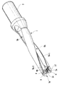
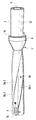
- FIG. 1 is a side view of a blade-tip replaceable drill according to an embodiment of the present invention.
- FIG. 2 is an enlarged view of a tip portion of the blade-tip replaceable drill of FIG.
- FIG. 3 is a front view of the tip portion of the blade-tip replaceable drill of FIG. 1 as viewed from the direction of the rotation axis.
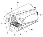
- FIG. 4 is a perspective view of the blade tip replaceable drill of FIG. 1.
- FIG. 5 is an enlarged view of a tip portion of the blade-tip replaceable drill shown in FIG.
- FIG. 6 is another perspective view of the blade tip replaceable drill shown in FIG. 1.
- FIG. 7 is an enlarged view of the distal end portion of FIG.
- FIG. 8 is a diagram schematically showing a cross-sectional structure of a hardened layer.
- 1 to 7 includes a drill body 1 and two cutting inserts 7A and 7B attached to the drill body 1.
- the drill body 1 is a substantially cylindrical member having a rotation axis O of a blade-exchangeable drill, and includes a shank portion 3, a flange portion 4, a first chip discharge groove 5A, a second chip discharge groove 5B, and The central blade mounting seat 6A and the outer peripheral blade mounting seat 6B are provided.
- the shank portion 3 is formed on the rear end side (right side in FIG. 1) of the rotation axis O of the drill body 1 in order to detachably mount the drill body 1 on a machine tool such as a machining center. As shown in FIG. 6, the shank portion 3 has a surface 3 f parallel to the rotation axis O.
- the flange portion 4 is provided adjacent to the shank 3 and has an end surface 4f that comes into contact with the main shaft of the machine tool or the end surface of the holder when mounted on the machine tool.
- the first and second chip discharging grooves 5A and 5B are formed in a spiral shape from the front end surface 1f of the drill body 1 toward the rear end side to the middle of the flange portion 4.
- the first and second chip discharge grooves 5A and 5B are grooves for discharging chips generated by the cutting inserts 7A and 7B from the front end surface 1f of the drill body 1 toward the rear end side.
- the first and second chip discharging grooves 5 ⁇ / b> A and 5 ⁇ / b> B are in a symmetric relationship with respect to the rotation axis O of the drill body 1.
- the first and second chip discharging grooves 5A and 5B are formed by the curved first wall surfaces 5A-1 and 5B-1 facing the drill rotation direction R shown in FIG. 3, and the first wall surfaces 5A. -1 and 5B-1 are defined by curved second wall surfaces 5A-2 and 5B-2 facing in the direction opposite to the tool rotation direction R, respectively.
- the center blade mounting seat 6A is formed in a concave shape on the first wall surface 5A-1 at the tip of the first chip discharging groove 5A in order to mount the cutting insert 7A.
- the outer peripheral blade mounting seat 6B is formed in a concave shape on the first wall surface 5B-1 at the tip of the second chip discharging groove 5B in order to mount the cutting insert 7B.
- the center blade mounting seat 6A arranges the cutting insert 7A closer to the rotational axis O, and the outer peripheral blade mounting seat 6B arranges the cutting insert 7B away from the rotational axis O.
- center blade mounting seat 6A and the outer peripheral blade mounting seat 6B are formed at the tip of the drill body 1, as shown in FIG. 3 and the like, the center blade mounting seat 6A and the second wall surface 5B-2 are interposed.
- the space between the outer peripheral blade mounting seat 6B and the second wall surface 5A-2 is a thinned wall portion 1w that is thinner than the rear wall portion.
- Each oil hole 9 opens at the front end face 1 f and the other end opens at the rear end face of the shank 3 of the drill body 1. .
- the oil hole 9 is provided for injecting the cutting oil from the tip surface 1f to a point where the cutting insert comes into contact with the workpiece (bottom edge of the cutting edge).
- the cutting inserts 7A and 7B attached to the center blade mounting seat 6A and the outer blade mounting seat 6B with the clamp bolts BT have the same structure, and in this embodiment, are formed from a hard material such as cemented carbide, cermet, or ceramic. It is a flat type positive cutting insert having a substantially parallelogram-shaped outer shape.
- the upper surface opposite to the seating surface constitutes a rake surface in a state where it is attached to the central blade mounting seat 6A and the outer peripheral blade mounting seat 6B. Constitutes the flank. In this embodiment, the clearance angle given to the flank is 11 °.
- a chip breaker that protrudes from the rake face is formed on the rake face. Further, a mounting hole penetrating from the rake face toward the seating face is formed at the center of the cutting inserts 7A and 7B.
- the cutting inserts 7 ⁇ / b> A and 7 ⁇ / b> B have cutting edges 7 a at the short sides of the substantially parallelogram, and cutting edges at the long sides of the intersection where the rake face and the flank face intersect. 7b, each corner portion forming an acute angle constitutes a cutting edge 7c.
- the cutting insert 7A hereinafter also referred to as the central blade insert 7A
- the cutting insert 7B hereinafter referred to as the outer peripheral blade insert). 7B
- the cutting edges 7a and 7b contribute to cutting.
- the cutting width by the outer peripheral blade insert 7B is shorter than the cutting width by the central blade insert 7A.
- a chip forming portion 8 is formed at the tip of the second wall surface 5A-2 of the first chip discharging groove 5A. Although not shown, a chip forming portion 8 is similarly formed on the second wall surface 5B-2 of the second chip discharging groove 5B.
- the formation region of the chip forming portion 8 is the above-described thinned wall portion 1w.
- the chip forming portion 8 has irregularities on the surface, and as will be described later, this irregularity reduces the substantial contact area when the chips generated by the cutting insert 7A directly contact with each other, thereby reducing friction. Further, the chip forming portion 8 has a surface hardness increased by forming a hardened layer having a higher hardness than other portions of the second wall surface 5A-2 in the vicinity of the surface.
- FIG. 8 schematically shows an example of a cross-sectional structure of the chip forming portion 8.
- the chip formation part 8 has the some convex part 8a and the recessed part 8b, and has the hardened layer 8c with high hardness in the surface vicinity.
- the chip formation part 8 is formed by laser processing, for example. Specifically, when the surface of the tip of the second wall surface 5A-2 is irradiated with laser light, the portion irradiated with the laser light is formed with a convex portion 8a and a concave portion 8b due to expansion or evaporation due to rapid heating.
- the formation range of the chip forming portion 8 that is, the range where the laser beam is irradiated can be recognized in advance. For this reason, as shown in FIG. 5 and FIG. 7, a marking MK that defines a formation range is formed in the boundary portion of the chip forming portion 8 or the like.
- the marking MK is formed by a plurality of shallow grooves or holes processed using, for example, a small diameter end mill or a small diameter drill.
- the chip forming portion 8 is laser-quenched at the same time, whereby the hardened layer 8c is formed. That is, the portion irradiated with the laser light is rapidly heated and then air-cooled, thereby forming a hardened layer 8c having a hardness higher than the hardness originally possessed by the drill body.
- a known laser processing apparatus can be used for laser processing.
- conditions such as laser beam output (average output), processing speed, and laser beam irradiation angle can be appropriately selected according to the height of the convex portion 8a, the depth of the concave portion 8b, the thickness of the hardened layer 8c, and the like. It is. Although it is desirable that the convex portions 8a and the concave portions 8b are regularly arranged and uniformly distributed from the viewpoint of keeping the contact state with the chips substantially constant, the present invention is not limited to this.
- the drill body 1 is subjected to heat treatment such as quenching and tempering in order to ensure sufficient hardness and toughness necessary for cutting, and has a substantially uniform basic hardness as a whole.
- the forming material of the drill body 1 is preferably carbon steel, alloy steel, tool steel, or the like having a property of hardening by quenching.
- alloy tool steel such as SKD11 (JIS G4404-2006) is used.
- the hardness of the hardened layer 8c of the chip forming portion 8 is higher than the basic hardness of the drill body 1, but the upper limit is preferably about Hv800.
- the thickness of the hardened layer 8c is preferably adjusted according to the thickness of the thinned wall portion 1w from the viewpoint of preventing brittle fracture of the thinned wall portion 1w, and in this embodiment, 0.05 mm to 0.00 mm. The thickness was in the range of 50 mm.
- the roughness of the surface of the chip forming portion 8 has a surface roughness exceeding 3 mm (JIS B0601-2001) at the maximum height Rz by forming irregularities.
- the wall surfaces 5A-1 and 5A-2 excluding the chip forming portion 8 are preferably smoothed as much as possible in order to increase the fluidity of chips and cutting oil.
- the height Rz was set to 3 ⁇ m (JIS B0601-2001) or less.
- the chip forming unit 8 covers a range in which chips scraped from the work body can first contact.
- the length of the chip forming portion 8 in the direction of the rotation axis O is preferably within a range from the front end portion of the second wall surface 5A-2 to the rear end side up to about the cutting edge diameter D of the drill.
- the size of the chip forming portion 8 in the radial direction of the drill main body 1 is spread over substantially the entire width direction of the second wall surface 5A-2.
- the workpiece is scraped by the center blade insert 7A and the outer peripheral blade insert 7B, and chips are continuously generated.
- the generated chips are discharged to the rear end side of the drill body 1 through the first chip discharging groove 5A and the second chip discharging groove 5B.
- cutting oil is continuously supplied from the opening of the oil hole to the cutting site.
- the cutting oil supplied to the cutting part flows in the first chip discharge groove 5A and the second chip discharge groove 5B to the rear end side together with the chips. As a result, the chips are forced to flow toward the rear end side of the drill body 1, and the discharge thereof is promoted.
- the chips scraped from the workpiece by the center blade insert 7A and the outer peripheral blade insert 7B are the chip forming portion 8 of the wall surfaces of the first and second chip discharge grooves 5A and 5B.
- This chip is deformed (curled) or broken due to contact with the chip forming portion 8. That is, since the above-mentioned unevenness is formed on the surface of the chip forming portion 8 to which the chip scraped off from the workpiece first contacts, the substantial contact area between the surface of the chip forming portion 8 and the chip is as follows. Reduced compared to smooth surface. For this reason, the frictional force which arises between the surface of the chip formation part 8 and chips can be reduced. As a result, the chips pass through the chip forming unit 8 more smoothly. In addition, since the frictional force between the chip forming portion 8 and the chips is reduced, drill vibration and chatter are also reduced.
- the hardened layer 8c of the chip forming portion 8 has a hardness exceeding the basic hardness of the drill body 1, wear of the chip forming portion 8 due to chip abrasion is suppressed. Therefore, the effect of reducing the frictional force between the above-described chip forming portion 8 and the chips is maintained for a long time.
- the chips continuously scraped from the workpiece are deformed (curled) in contact with the chip forming portion 8 and then broken, and then completely released from the workpiece. For this reason, by making the wall surface downstream from the chip forming portion 8 a smooth surface, the flow of chips and cutting oil is not hindered, and the first chip discharging groove 5A and the second chip discharging groove 5B. Chips can be discharged smoothly toward the rear end side.
- the first chip discharging groove 5A and the second chip discharging groove 5B are formed in a spiral shape, but can be changed to a groove extending linearly in a direction parallel to the rotation axis O. It is. Moreover, although the chip formation part 8 demonstrated the case where it formed in both the 1st chip discharge groove
- Quenching of the hardened layer 8c of the chip forming portion 8 is not limited to laser quenching, and may be replaced by electron beam quenching, induction quenching, or the like.
- the unevenness may be formed by machining using an end mill or the like in the chip forming portion 8 after forming a hardened layer by laser quenching. Is possible.
Landscapes
- Engineering & Computer Science (AREA)
- Chemical & Material Sciences (AREA)
- Mechanical Engineering (AREA)
- Physics & Mathematics (AREA)
- Thermal Sciences (AREA)
- Crystallography & Structural Chemistry (AREA)
- Materials Engineering (AREA)
- Metallurgy (AREA)
- Organic Chemistry (AREA)
- Drilling Tools (AREA)
Abstract
Description
Claims (12)
- 回転軸線方向の先端面から後端側に向けて形成された、切削用インサートにより生成された切屑を排出するための切屑排出用溝と、該切屑排出用溝のドリル回転方向を向く第1壁面の回転軸線方向の先端側に形成された切削用インサートが取り外し可能に装着されるインサート取付座とを有する刃先交換式ドリルのドリル本体であって、
前記切屑排出用溝を画定する壁面のうち、少なくとも前記切屑排出溝のドリル回転方向後方側を向く第2壁面の先端部分に、第2壁面から外方へ向かって突出する複数の突起部、又は前記第2壁面から内方へ向かって凹む複数の凹部の少なくともいずれかを備えた切屑形成部が形成された、ことを特徴とするドリル本体。 - 前記切屑形成部は、その表面近傍に前記壁面の他の領域よりも硬度が高められた硬化層を有する、ことを特徴とする請求項1に記載のドリル本体。
- 前記切屑形成部は前記切屑排出用溝の先端部分にのみ形成されていることを特徴とする請求項1または2に記載のドリル本体。
- 前記壁面には、前記切屑形成部の形成範囲を画定するマーキングが形成されている、ことを特徴とする請求項1ないし3のいずれかに記載のドリル本体。
- 前記切屑形成部の表面粗さは、前記切屑形成部を除く前記壁部の表面粗さより大きい、ことを特徴とする請求項1ないし4のいずれかに記載のドリル本体。
- 前記切屑形成部を除く前記壁面の表面粗さは、最大高さRzで、3μm(JIS・B0601-2001)以下であることを特徴とする請求項5に記載のドリル本体。
- 前記インサート取付座は、切削用インサートを回転軸線寄りに装着するための中心刃取付座と、切削用インサートを回転軸線から離れて装着するための外周刃取付座とを含み、
前記切屑排出用溝の壁面の一部は、前記中心刃取付座および外周刃取付座により薄肉化された薄肉化壁部に形成され、
前記硬化層は、前記薄肉化壁部の表面近傍に形成されている、ことを特徴とする請求項2ないし6のいずれかに記載のドリル本体。 - 前記硬化層がHv800以下の硬度を有する、請求項2ないし7のいずれかに記載のドリル本体。
- 前記硬化層が前記切屑形成部の表面から内部へ0.05mm以上、0.50mm以下の深さにわたって存在している、請求項2ないし8のいずれかに記載のドリル本体。
- 前記切屑形成部の突起部又は凹部は、レーザー加工により形成されている、ことを特徴とする請求項1ないし9のいずれかに記載のドリル本体。
- 前記硬化層は、レーザー焼入れによって硬化されている、請求項10に記載のドリル本体。
- 回転軸線方向の先端面から後端側に向けて形成された、切削用インサートにより生成された切屑を排出するための切屑排出用溝と、該切屑排出用溝のドリル回転方向を向く第1壁面の回転軸線方向の先端側に形成されたインサート取付座とを有すドリル本体と、前記インサート取付座に取り外し可能に装着される切削用インサートを有する刃先交換式ドリルであって、
前記ドリル本体は、前記切屑排出用溝を画定する壁面のうち、少なくとも前記切屑排出溝のドリル回転方向後方側を向く第2壁面の先端部分に、第2壁面から外方へ向かって突出する複数の突起部、又は前記第2壁面から内方へ向かって凹む複数の凹部の少なくともいずれかを備えた切屑形成部が形成された、ことを特徴とする刃先交換式ドリル。
Priority Applications (7)
| Application Number | Priority Date | Filing Date | Title |
|---|---|---|---|
| JP2011516076A JPWO2010137701A1 (ja) | 2009-05-29 | 2010-05-28 | 刃先交換式ドリルおよびドリル本体 |
| EP10780655A EP2436466A1 (en) | 2009-05-29 | 2010-05-28 | Indexable drill and drill body |
| RU2011148443/02A RU2496612C2 (ru) | 2009-05-29 | 2010-05-28 | Сверло с индексируемыми режущими пластинами и корпус сверла |
| CA2763957A CA2763957C (en) | 2009-05-29 | 2010-05-28 | Indexable drill and drill body |
| BRPI1011341A BRPI1011341A2 (pt) | 2009-05-29 | 2010-05-28 | corpo de broca, e, broca indexável |
| CN2010800250308A CN102448647A (zh) | 2009-05-29 | 2010-05-28 | 刀尖交换式钻头及钻头本体 |
| US13/300,307 US20120063858A1 (en) | 2009-05-29 | 2011-11-18 | Indexable Drill and Drill Body |
Applications Claiming Priority (2)
| Application Number | Priority Date | Filing Date | Title |
|---|---|---|---|
| JP2009129767 | 2009-05-29 | ||
| JP2009-129767 | 2009-05-29 |
Related Child Applications (1)
| Application Number | Title | Priority Date | Filing Date |
|---|---|---|---|
| US13/300,307 Continuation US20120063858A1 (en) | 2009-05-29 | 2011-11-18 | Indexable Drill and Drill Body |
Publications (1)
| Publication Number | Publication Date |
|---|---|
| WO2010137701A1 true WO2010137701A1 (ja) | 2010-12-02 |
Family
ID=43222804
Family Applications (1)
| Application Number | Title | Priority Date | Filing Date |
|---|---|---|---|
| PCT/JP2010/059134 Ceased WO2010137701A1 (ja) | 2009-05-29 | 2010-05-28 | 刃先交換式ドリルおよびドリル本体 |
Country Status (9)
| Country | Link |
|---|---|
| US (1) | US20120063858A1 (ja) |
| EP (1) | EP2436466A1 (ja) |
| JP (1) | JPWO2010137701A1 (ja) |
| KR (1) | KR20120022941A (ja) |
| CN (1) | CN102448647A (ja) |
| BR (1) | BRPI1011341A2 (ja) |
| CA (1) | CA2763957C (ja) |
| RU (1) | RU2496612C2 (ja) |
| WO (1) | WO2010137701A1 (ja) |
Cited By (5)
| Publication number | Priority date | Publication date | Assignee | Title |
|---|---|---|---|---|
| US20140341667A1 (en) * | 2011-09-16 | 2014-11-20 | Osg Corporation | Drill body of indexable drill |
| CN108349020A (zh) * | 2015-11-09 | 2018-07-31 | 京瓷株式会社 | 切削刀片、切削工具以及切削加工物的制造方法 |
| US10549358B2 (en) | 2015-02-26 | 2020-02-04 | Kyocera Corporation | Insert, drill, and method of manufacturing machined product using the same |
| JP2020069584A (ja) * | 2018-10-31 | 2020-05-07 | 株式会社タンガロイ | 刃先交換式転削工具用ボデー及び刃先交換式転削工具 |
| US10668540B2 (en) | 2015-03-23 | 2020-06-02 | Kyocera Corporation | Insert, drill, and method of manufacturing machined product using the same |
Families Citing this family (4)
| Publication number | Priority date | Publication date | Assignee | Title |
|---|---|---|---|---|
| DE102014103906B4 (de) * | 2014-03-21 | 2022-08-25 | Gühring KG | Partiell gehärtetes Drehwerkzeug und diesbezügliches Herstellverfahren |
| EP3034214A1 (en) * | 2014-12-19 | 2016-06-22 | Pramet Tools, S.R.O. | Drill and drill insert with chipbreaker protrusions |
| CN105714074A (zh) * | 2016-01-12 | 2016-06-29 | 北京莱思创激光技术有限公司 | 一种螺丝刀的激光淬火方法 |
| EP3401043B1 (en) * | 2017-05-11 | 2020-03-25 | Sandvik Intellectual Property AB | Drill body and drill |
Citations (6)
| Publication number | Priority date | Publication date | Assignee | Title |
|---|---|---|---|---|
| JPH0691416A (ja) | 1992-07-31 | 1994-04-05 | Mitsubishi Materials Corp | スローアウェイ式穴明け工具およびスローアウェイチップ |
| DE4241140A1 (de) * | 1992-12-07 | 1994-06-09 | Krupp Widia Gmbh | Zerspannungswerkzeug |
| JPH10508546A (ja) * | 1994-11-10 | 1998-08-25 | ケンナメタル ヘルテル アクチェンゲゼルシャフト ウェルクツォイゲ ウント ハルトシュトッフェ | 穿孔工具 |
| JP2005279887A (ja) * | 2004-03-30 | 2005-10-13 | Mitsubishi Materials Kobe Tools Corp | 溝付き工具 |
| JP2006212725A (ja) * | 2005-02-02 | 2006-08-17 | Hitachi Tool Engineering Ltd | アルミ高能率加工用ドリル |
| WO2007126647A2 (en) * | 2006-04-04 | 2007-11-08 | Kennametal Inc. | Toolholder with chip ejection segment thereupon |
Family Cites Families (22)
| Publication number | Priority date | Publication date | Assignee | Title |
|---|---|---|---|---|
| US2322894A (en) * | 1939-06-29 | 1943-06-29 | Rustless Iron & Steel Corp | Twist drill |
| SU607670A1 (ru) * | 1976-01-22 | 1978-04-25 | Волгоградский Политехнический Институт | Бесперемычное сверло дл сплошного сверлени глубоких отверстий |
| US4802799A (en) * | 1987-06-10 | 1989-02-07 | Marken Tool Company | Drill bit |
| JP2964664B2 (ja) * | 1991-02-27 | 1999-10-18 | 住友電気工業株式会社 | ダイヤモンド被覆マイクロドリル |
| DE4231381A1 (de) * | 1992-09-19 | 1994-03-24 | Mitsubishi Materials Corp | Bohrer |
| DK173819B1 (da) * | 1994-07-22 | 2001-11-19 | Niels Joergen Hansen | Holdeorgan til skæreorganer og fremgangsmåde til fremstilling af et sådant holdeorgan |
| EP0796162B1 (de) * | 1994-12-10 | 1998-04-15 | KENNAMETAL HERTEL AG Werkzeuge + Hartstoffe | Bohrwerkzeug für bohrungen in metallvollmaterial |
| BR9607878A (pt) * | 1995-03-30 | 1999-11-30 | Vilab Ag | Ferramenta de corte. |
| US5704740A (en) * | 1995-06-26 | 1998-01-06 | Walter Ag | Drilling tool, particularly for metallic materials |
| JPH10134345A (ja) * | 1995-10-23 | 1998-05-22 | Mitsubishi Chem Corp | 磁気記録媒体およびその製造方法 |
| US5716170A (en) * | 1996-05-15 | 1998-02-10 | Kennametal Inc. | Diamond coated cutting member and method of making the same |
| JPH10235508A (ja) * | 1997-02-27 | 1998-09-08 | Mitsubishi Materials Corp | 穴明け工具 |
| DE19724319C1 (de) * | 1997-06-10 | 1998-10-08 | Fette Wilhelm Gmbh | Verfahren zur Beeinflussung des Spanflußverhaltens von Werkzeugflächen |
| JPH116011A (ja) * | 1997-06-13 | 1999-01-12 | Aisin Aw Co Ltd | 凹凸面を有する金属部材及びその製造方法 |
| US6056486A (en) * | 1998-07-15 | 2000-05-02 | Colvin; Kevin F. | Cutting tool point |
| DE19905735A1 (de) * | 1999-02-11 | 2000-08-17 | Kennametal Inc | Verfahren zum Herstellen eines Zerspanungswerkzeugs sowie Zerspanungswerkzeug |
| US20010031181A1 (en) * | 1999-12-22 | 2001-10-18 | Shallenberger Fred T. | Indexable drill and cutting inserts therefor |
| IL145574A0 (en) * | 2001-09-24 | 2002-06-30 | Iscar Ltd | Cutting tool and cutting insert therefor |
| US7306411B2 (en) * | 2002-09-03 | 2007-12-11 | Mitsubishi Materials Corporation | Drill with groove width variation along the drill and double margin with a thinning section at the tip |
| US7131799B2 (en) * | 2003-12-19 | 2006-11-07 | Allied Machine & Engineering Corp. | Cutting insert with helical geometry and holder therefor |
| JP2009101460A (ja) * | 2007-10-23 | 2009-05-14 | Omi Kogyo Co Ltd | 切削工具 |
| CN102802850A (zh) * | 2009-06-02 | 2012-11-28 | 株式会社钨钛合金 | 刀头更换式钻头及钻头主体 |
-
2010
- 2010-05-28 RU RU2011148443/02A patent/RU2496612C2/ru not_active IP Right Cessation
- 2010-05-28 BR BRPI1011341A patent/BRPI1011341A2/pt not_active IP Right Cessation
- 2010-05-28 JP JP2011516076A patent/JPWO2010137701A1/ja active Pending
- 2010-05-28 WO PCT/JP2010/059134 patent/WO2010137701A1/ja not_active Ceased
- 2010-05-28 KR KR1020117027043A patent/KR20120022941A/ko not_active Abandoned
- 2010-05-28 EP EP10780655A patent/EP2436466A1/en not_active Withdrawn
- 2010-05-28 CA CA2763957A patent/CA2763957C/en not_active Expired - Fee Related
- 2010-05-28 CN CN2010800250308A patent/CN102448647A/zh active Pending
-
2011
- 2011-11-18 US US13/300,307 patent/US20120063858A1/en not_active Abandoned
Patent Citations (6)
| Publication number | Priority date | Publication date | Assignee | Title |
|---|---|---|---|---|
| JPH0691416A (ja) | 1992-07-31 | 1994-04-05 | Mitsubishi Materials Corp | スローアウェイ式穴明け工具およびスローアウェイチップ |
| DE4241140A1 (de) * | 1992-12-07 | 1994-06-09 | Krupp Widia Gmbh | Zerspannungswerkzeug |
| JPH10508546A (ja) * | 1994-11-10 | 1998-08-25 | ケンナメタル ヘルテル アクチェンゲゼルシャフト ウェルクツォイゲ ウント ハルトシュトッフェ | 穿孔工具 |
| JP2005279887A (ja) * | 2004-03-30 | 2005-10-13 | Mitsubishi Materials Kobe Tools Corp | 溝付き工具 |
| JP2006212725A (ja) * | 2005-02-02 | 2006-08-17 | Hitachi Tool Engineering Ltd | アルミ高能率加工用ドリル |
| WO2007126647A2 (en) * | 2006-04-04 | 2007-11-08 | Kennametal Inc. | Toolholder with chip ejection segment thereupon |
Cited By (9)
| Publication number | Priority date | Publication date | Assignee | Title |
|---|---|---|---|---|
| US20140341667A1 (en) * | 2011-09-16 | 2014-11-20 | Osg Corporation | Drill body of indexable drill |
| US9446457B2 (en) * | 2011-09-16 | 2016-09-20 | Osg Corporation | Drill body of indexable drill |
| US10549358B2 (en) | 2015-02-26 | 2020-02-04 | Kyocera Corporation | Insert, drill, and method of manufacturing machined product using the same |
| US10668540B2 (en) | 2015-03-23 | 2020-06-02 | Kyocera Corporation | Insert, drill, and method of manufacturing machined product using the same |
| DE112016001367B4 (de) | 2015-03-23 | 2023-08-17 | Kyocera Corporation | Einsatz, Bohrer und Verfahren des Herstellens eines maschinell bearbeiteten Produkts unter Verwendung derselben |
| CN108349020A (zh) * | 2015-11-09 | 2018-07-31 | 京瓷株式会社 | 切削刀片、切削工具以及切削加工物的制造方法 |
| US10632540B2 (en) | 2015-11-09 | 2020-04-28 | Kyocera Corporation | Cutting insert, cutting tool, and method of manufacturing machined product |
| DE112016005138B4 (de) * | 2015-11-09 | 2024-02-29 | Kyocera Corporation | Schneidwerkzeug und Verfahren des Herstellens eines maschinell-bearbeiteten Produkts |
| JP2020069584A (ja) * | 2018-10-31 | 2020-05-07 | 株式会社タンガロイ | 刃先交換式転削工具用ボデー及び刃先交換式転削工具 |
Also Published As
| Publication number | Publication date |
|---|---|
| CA2763957A1 (en) | 2010-12-02 |
| KR20120022941A (ko) | 2012-03-12 |
| RU2011148443A (ru) | 2013-07-10 |
| CA2763957C (en) | 2013-09-10 |
| US20120063858A1 (en) | 2012-03-15 |
| BRPI1011341A2 (pt) | 2016-03-08 |
| CN102448647A (zh) | 2012-05-09 |
| EP2436466A1 (en) | 2012-04-04 |
| JPWO2010137701A1 (ja) | 2012-11-15 |
| RU2496612C2 (ru) | 2013-10-27 |
Similar Documents
| Publication | Publication Date | Title |
|---|---|---|
| WO2010137701A1 (ja) | 刃先交換式ドリルおよびドリル本体 | |
| JP4919182B2 (ja) | 穴あけ工具 | |
| JP5286933B2 (ja) | ドリル | |
| JP5763331B2 (ja) | 仕上げフライス切削用の正面フライス | |
| JPWO2010140606A1 (ja) | 刃先交換式ドリルおよびドリル本体 | |
| JP2003300110A (ja) | ドリルおよびその製造方法 | |
| CN110035858B (zh) | 具有冷却剂流动凹槽的铣削刀具 | |
| KR102868278B1 (ko) | 드릴 및 피천공품의 제조 방법 | |
| KR20140002622A (ko) | 냉매 시스템을 갖는 절삭 공구 및 이를 위한 체결부재 | |
| US10661362B2 (en) | Fluted cutting tool configuration and method therefor | |
| US20180093330A1 (en) | Cutting tool and method for its manufacture | |
| CN107107208A (zh) | 具有断屑器突起的钻头及钻头刀片 | |
| KR20250051699A (ko) | 단차 드릴 및 단차 드릴을 이용한 가공물 천공 방법 | |
| JP5287426B2 (ja) | 切削工具 | |
| JP4529383B2 (ja) | ドリル | |
| JP5953173B2 (ja) | 切削工具 | |
| JP2010214545A (ja) | エンドミル | |
| US20200331078A1 (en) | Method for Machining Titanium Alloys Using Polycrystalline Diamond | |
| JP2003117710A (ja) | クーラント穴付き穴明け工具 | |
| CN100417476C (zh) | 高硬度、高粘性材料加工用可转位车削刀片 | |
| JP2009066715A (ja) | 切削工具 | |
| RU158628U1 (ru) | Концевая фреза со сменными режущими пластинами, имеющая повышенную стойкость | |
| JP2009136998A (ja) | ドリル | |
| JP5055869B2 (ja) | スローアウェイ式回転工具 | |
| Klimenko | Krol OS, Romanchenko OV, Mitsyk AV |
Legal Events
| Date | Code | Title | Description |
|---|---|---|---|
| WWE | Wipo information: entry into national phase |
Ref document number: 201080025030.8 Country of ref document: CN |
|
| 121 | Ep: the epo has been informed by wipo that ep was designated in this application |
Ref document number: 10780655 Country of ref document: EP Kind code of ref document: A1 |
|
| DPE1 | Request for preliminary examination filed after expiration of 19th month from priority date (pct application filed from 20040101) | ||
| WWE | Wipo information: entry into national phase |
Ref document number: 2011516076 Country of ref document: JP |
|
| ENP | Entry into the national phase |
Ref document number: 20117027043 Country of ref document: KR Kind code of ref document: A |
|
| WWE | Wipo information: entry into national phase |
Ref document number: 8952/DELNP/2011 Country of ref document: IN Ref document number: 2010780655 Country of ref document: EP |
|
| NENP | Non-entry into the national phase |
Ref country code: DE |
|
| WWE | Wipo information: entry into national phase |
Ref document number: 2763957 Country of ref document: CA |
|
| ENP | Entry into the national phase |
Ref document number: 2011148443 Country of ref document: RU Kind code of ref document: A |
|
| REG | Reference to national code |
Ref country code: BR Ref legal event code: B01A Ref document number: PI1011341 Country of ref document: BR |
|
| ENP | Entry into the national phase |
Ref document number: PI1011341 Country of ref document: BR Kind code of ref document: A2 Effective date: 20111129 |