WO2010137680A1 - 画像処理装置、電子装置、および、画像処理方法 - Google Patents
画像処理装置、電子装置、および、画像処理方法 Download PDFInfo
- Publication number
- WO2010137680A1 WO2010137680A1 PCT/JP2010/059069 JP2010059069W WO2010137680A1 WO 2010137680 A1 WO2010137680 A1 WO 2010137680A1 JP 2010059069 W JP2010059069 W JP 2010059069W WO 2010137680 A1 WO2010137680 A1 WO 2010137680A1
- Authority
- WO
- WIPO (PCT)
- Prior art keywords
- vehicle
- image
- composite
- image processing
- images
- Prior art date
- Legal status (The legal status is an assumption and is not a legal conclusion. Google has not performed a legal analysis and makes no representation as to the accuracy of the status listed.)
- Ceased
Links
Images





Classifications
-
- G—PHYSICS
- G08—SIGNALLING
- G08G—TRAFFIC CONTROL SYSTEMS
- G08G1/00—Traffic control systems for road vehicles
- G08G1/16—Anti-collision systems
- G08G1/167—Driving aids for lane monitoring, lane changing, e.g. blind spot detection
-
- B—PERFORMING OPERATIONS; TRANSPORTING
- B60—VEHICLES IN GENERAL
- B60R—VEHICLES, VEHICLE FITTINGS, OR VEHICLE PARTS, NOT OTHERWISE PROVIDED FOR
- B60R1/00—Optical viewing arrangements; Real-time viewing arrangements for drivers or passengers using optical image capturing systems, e.g. cameras or video systems specially adapted for use in or on vehicles
- B60R1/20—Real-time viewing arrangements for drivers or passengers using optical image capturing systems, e.g. cameras or video systems specially adapted for use in or on vehicles
- B60R1/22—Real-time viewing arrangements for drivers or passengers using optical image capturing systems, e.g. cameras or video systems specially adapted for use in or on vehicles for viewing an area outside the vehicle, e.g. the exterior of the vehicle
- B60R1/23—Real-time viewing arrangements for drivers or passengers using optical image capturing systems, e.g. cameras or video systems specially adapted for use in or on vehicles for viewing an area outside the vehicle, e.g. the exterior of the vehicle with a predetermined field of view
- B60R1/27—Real-time viewing arrangements for drivers or passengers using optical image capturing systems, e.g. cameras or video systems specially adapted for use in or on vehicles for viewing an area outside the vehicle, e.g. the exterior of the vehicle with a predetermined field of view providing all-round vision, e.g. using omnidirectional cameras
-
- B—PERFORMING OPERATIONS; TRANSPORTING
- B60—VEHICLES IN GENERAL
- B60R—VEHICLES, VEHICLE FITTINGS, OR VEHICLE PARTS, NOT OTHERWISE PROVIDED FOR
- B60R1/00—Optical viewing arrangements; Real-time viewing arrangements for drivers or passengers using optical image capturing systems, e.g. cameras or video systems specially adapted for use in or on vehicles
- B60R1/20—Real-time viewing arrangements for drivers or passengers using optical image capturing systems, e.g. cameras or video systems specially adapted for use in or on vehicles
- B60R1/22—Real-time viewing arrangements for drivers or passengers using optical image capturing systems, e.g. cameras or video systems specially adapted for use in or on vehicles for viewing an area outside the vehicle, e.g. the exterior of the vehicle
- B60R1/28—Real-time viewing arrangements for drivers or passengers using optical image capturing systems, e.g. cameras or video systems specially adapted for use in or on vehicles for viewing an area outside the vehicle, e.g. the exterior of the vehicle with an adjustable field of view
-
- G—PHYSICS
- G06—COMPUTING OR CALCULATING; COUNTING
- G06T—IMAGE DATA PROCESSING OR GENERATION, IN GENERAL
- G06T3/00—Geometric image transformations in the plane of the image
- G06T3/40—Scaling of whole images or parts thereof, e.g. expanding or contracting
- G06T3/4038—Image mosaicing, e.g. composing plane images from plane sub-images
-
- G—PHYSICS
- G08—SIGNALLING
- G08G—TRAFFIC CONTROL SYSTEMS
- G08G1/00—Traffic control systems for road vehicles
- G08G1/09—Arrangements for giving variable traffic instructions
- G08G1/0962—Arrangements for giving variable traffic instructions having an indicator mounted inside the vehicle, e.g. giving voice messages
-
- G—PHYSICS
- G08—SIGNALLING
- G08G—TRAFFIC CONTROL SYSTEMS
- G08G1/00—Traffic control systems for road vehicles
- G08G1/16—Anti-collision systems
- G08G1/165—Anti-collision systems for passive traffic, e.g. including static obstacles, trees
-
- G—PHYSICS
- G08—SIGNALLING
- G08G—TRAFFIC CONTROL SYSTEMS
- G08G1/00—Traffic control systems for road vehicles
- G08G1/16—Anti-collision systems
- G08G1/166—Anti-collision systems for active traffic, e.g. moving vehicles, pedestrians, bikes
-
- G—PHYSICS
- G08—SIGNALLING
- G08G—TRAFFIC CONTROL SYSTEMS
- G08G1/00—Traffic control systems for road vehicles
- G08G1/16—Anti-collision systems
- G08G1/168—Driving aids for parking, e.g. acoustic or visual feedback on parking space
-
- H—ELECTRICITY
- H04—ELECTRIC COMMUNICATION TECHNIQUE
- H04N—PICTORIAL COMMUNICATION, e.g. TELEVISION
- H04N7/00—Television systems
- H04N7/18—Closed-circuit television [CCTV] systems, i.e. systems in which the video signal is not broadcast
-
- H—ELECTRICITY
- H04—ELECTRIC COMMUNICATION TECHNIQUE
- H04N—PICTORIAL COMMUNICATION, e.g. TELEVISION
- H04N7/00—Television systems
- H04N7/18—Closed-circuit television [CCTV] systems, i.e. systems in which the video signal is not broadcast
- H04N7/181—Closed-circuit television [CCTV] systems, i.e. systems in which the video signal is not broadcast for receiving images from a plurality of remote sources
-
- B—PERFORMING OPERATIONS; TRANSPORTING
- B60—VEHICLES IN GENERAL
- B60R—VEHICLES, VEHICLE FITTINGS, OR VEHICLE PARTS, NOT OTHERWISE PROVIDED FOR
- B60R2300/00—Details of viewing arrangements using cameras and displays, specially adapted for use in a vehicle
- B60R2300/30—Details of viewing arrangements using cameras and displays, specially adapted for use in a vehicle characterised by the type of image processing
- B60R2300/303—Details of viewing arrangements using cameras and displays, specially adapted for use in a vehicle characterised by the type of image processing using joined images, e.g. multiple camera images
-
- B—PERFORMING OPERATIONS; TRANSPORTING
- B60—VEHICLES IN GENERAL
- B60R—VEHICLES, VEHICLE FITTINGS, OR VEHICLE PARTS, NOT OTHERWISE PROVIDED FOR
- B60R2300/00—Details of viewing arrangements using cameras and displays, specially adapted for use in a vehicle
- B60R2300/60—Details of viewing arrangements using cameras and displays, specially adapted for use in a vehicle characterised by monitoring and displaying vehicle exterior scenes from a transformed perspective
- B60R2300/602—Details of viewing arrangements using cameras and displays, specially adapted for use in a vehicle characterised by monitoring and displaying vehicle exterior scenes from a transformed perspective with an adjustable viewpoint
-
- B—PERFORMING OPERATIONS; TRANSPORTING
- B60—VEHICLES IN GENERAL
- B60R—VEHICLES, VEHICLE FITTINGS, OR VEHICLE PARTS, NOT OTHERWISE PROVIDED FOR
- B60R2300/00—Details of viewing arrangements using cameras and displays, specially adapted for use in a vehicle
- B60R2300/80—Details of viewing arrangements using cameras and displays, specially adapted for use in a vehicle characterised by the intended use of the viewing arrangement
- B60R2300/806—Details of viewing arrangements using cameras and displays, specially adapted for use in a vehicle characterised by the intended use of the viewing arrangement for aiding parking
Definitions
- the present invention relates to a technique for displaying an image on a display device mounted on a vehicle.
- a device that enables monitoring of the periphery of a vehicle by acquiring images around the vehicle with a plurality of cameras mounted on the vehicle and displaying them on a display device automatically or by user operation.
- an apparatus that displays on the screen an image looking down directly above the vehicle as a virtual viewpoint, and provides a user with means for confirming safety around the entire vehicle.
- a first screen is displayed on the first screen, in which a plurality of cameras mounted on the vehicle are used to shoot from a viewpoint at a predetermined height, and the viewpoint position of the image captured by the camera is displayed together with an overall view of the vehicle.
- the second screen of OLE_LINK1 that displays each camera image, corresponding to the movement of the OLE_LINK1 viewpoint position (see, for example, Patent Document 1).
- a screen showing the position of the viewpoint of the image captured by the camera together with the overall view of the vehicle, and a screen for displaying each camera image corresponding to the movement of the viewpoint position are displayed on different screens, and the information displayed on the two screens must be correlated by the user himself, which makes it difficult for the user to grasp the positional relationship between the vehicle and the obstacle.
- the present invention has been made in view of the above problems, and an object thereof is to provide a technique that allows a user to intuitively grasp the positional relationship between a vehicle and an obstacle around the vehicle.
- An image processing device that processes an image to be displayed on a display device mounted on a vehicle, based on a receiving unit that receives an instruction signal and a plurality of images around the vehicle that are captured by a plurality of cameras.
- a composite image generating unit that generates a plurality of first composite images when the vehicle is viewed from a plurality of virtual viewpoints arranged above the periphery of the vehicle, and the instruction signal so that the virtual viewpoints continuously circulate
- an output unit that continuously outputs the plurality of first composite images to the display device.
- the composite image generation unit generates a second composite image in which the vehicle is viewed from a virtual viewpoint arranged immediately above the center of the vehicle, and the output A unit configured to display the plurality of first synthesized images and the second synthesized images on the display device such that the virtual viewpoint continuously moves between the plurality of first synthesized images and the second synthesized images. Are output continuously.
- the output unit outputs the second composite image after outputting the plurality of first composite images.
- the composite image generation unit circulates the plurality of first composite images with the virtual viewpoint around the position of the vehicle. To generate.
- the composite image generation unit circulates the plurality of first composite images with the virtual viewpoint around the position of the vehicle. To generate.
- the receiving unit receives the instruction signal when the image processing device is activated.
- An electronic device that processes an image to be displayed on a display device mounted on a vehicle, the operation unit outputting an instruction signal, the receiving unit receiving the instruction signal, and the image taken by a plurality of cameras Based on a plurality of images around the vehicle, a composite image generation unit that generates a composite image in which the virtual viewpoint continuously circulates when viewed from the virtual viewpoint arranged above the periphery of the vehicle, and An output unit that outputs the composite image to the display device in response to an instruction signal.
- the electronic device further including the display device that displays the composite image output from the output unit.
- An image processing method for processing an image to be displayed on a display device mounted on a vehicle the step of receiving an instruction signal, and a plurality of images around the vehicle photographed by a plurality of cameras In response to the instruction signal so that the virtual viewpoint continuously circulates, and a step of generating a plurality of composite images of the vehicle viewed from the plurality of virtual viewpoints arranged above the periphery of the vehicle. And successively outputting the plurality of synthesized images to the display device.
- both a plurality of composite images showing the virtual viewpoint moving with continuity and turning around the vehicle and a composite image viewed from above the vehicle are displayed.
- the user can intuitively grasp the positional relationship between the vehicle and the obstacle on one screen.
- safety around the vehicle can be confirmed from a plurality of viewpoints around the vehicle and above the vehicle.
- the upper part of the vehicle is displayed with continuity after the surrounding image of the vehicle.
- Safety confirmation can be performed again using images.
- the user does not need to check a wide range of the entire periphery of the vehicle at a time, and continuously displays an image of the entire vehicle in a wide range above the vehicle after an image of a limited range around the vehicle. Can confirm the safety around the vehicle more reliably on one screen.
- the user can confirm the safety centering on an arbitrary point around the vehicle to be confirmed on one screen by focusing on the point designated by the user around the vehicle. .
- the user can confirm the periphery of the vehicle on one screen when the image processing apparatus is activated.
- FIG. 1 is a block diagram of an image display system.
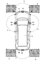
- FIG. 2 is a diagram illustrating positions where a plurality of in-vehicle cameras are arranged in the vehicle.
- FIG. 3 is a diagram illustrating a method for generating a composite image viewed from an arbitrary virtual viewpoint.
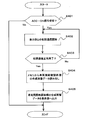
- FIG. 4 is a diagram illustrating a flow of processing of the image processing unit.
- FIG. 5 is a diagram illustrating screen transition of the composite image in the first embodiment.
- FIG. 6 is a diagram illustrating a flow of display processing of the display unit.
- FIG. 7 is a diagram illustrating a screen transition of the composite image in the second embodiment.
- FIG. 8 is a diagram illustrating a first modification of the processing of the image processing unit.
- FIG. 1 is a block diagram of an image display system.
- FIG. 2 is a diagram illustrating positions where a plurality of in-vehicle cameras are arranged in the vehicle.
- FIG. 3 is a diagram illustrating a method for
- FIG. 9 is a diagram illustrating a second modification of the processing of the image processing unit.
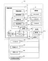
- FIG. 10 is a block diagram of an image display system according to the third embodiment.
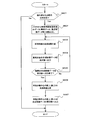
- FIG. 11 is a diagram illustrating a processing flow of the image processing unit according to the third embodiment.
- FIG. 12 is a diagram illustrating screen transition of the composite image according to the third embodiment.
- FIG. 13 is a diagram illustrating a first modification of the process of the image processing unit of the third embodiment.
- FIG. 14 is a diagram illustrating a second modification of the process of the image processing unit according to the third embodiment.
- FIG. 1 is a block diagram of an image display system 100 according to the first embodiment.
- the image display system 100 is an electronic device that is mounted on a vehicle (in this embodiment, an automobile), and has a function of photographing the periphery of the vehicle to generate an image and displaying the image in the vehicle interior.
- a driver of a vehicle serving as a user who uses the image display system 100 can easily grasp the periphery of the vehicle.
- the image display system 100 includes an image processing unit 10 and a photographing unit 5 that photographs the periphery of the vehicle.
- the image display system 100 includes a display unit 21 such as a liquid crystal display, and is installed on an instrument panel or the like of a vehicle so that the screen of the display unit 21 is visible from a driver.
- the image processing unit 10 processes an image to be displayed on the display unit 21.
- the photographing unit 5 is electrically connected to the image processing unit 10 and operates based on a signal from the image processing unit 10.
- the display unit 21 has a touch panel function and can accept various instructions from the user.
- the photographing unit 5 includes a front camera 51, a side camera 52, and a back camera 53, which are in-vehicle cameras. These in-vehicle cameras 51, 52, and 53 include a lens and an image sensor and electronically acquire an image.
- FIG. 2 is a diagram showing positions where the in-vehicle cameras 51, 52, 53 are arranged on the vehicle 9.
- the front camera 51 is provided at the substantially left and right center of the front bumper 91 that is the front end of the vehicle 9, and its optical axis is directed in the straight traveling direction of the vehicle 9.
- the side cameras 52 are provided on the left and right door mirrors 93, respectively, and their optical axes are directed to the outside of the vehicle 9 so as to be orthogonal to the straight traveling direction.
- the back camera 53 is provided at the substantially right and left center of the rear bumper 92 that is the rear end of the vehicle 9, and its optical axis is directed in the direction opposite to the straight traveling direction of the vehicle 9.
- a fish-eye lens or the like is employed as the lens of these in-vehicle cameras 51, 52, 53, and the in-vehicle cameras 51, 52, 53 have an angle of view ⁇ of 180 degrees or more. For this reason, it is possible to shoot the entire periphery of the vehicle 9 by using the four in-vehicle cameras 51, 52, and 53.
- the vehicle-mounted cameras 51, 52, and 53 have an angle of view ⁇ of 180 degrees or more, an overlapping region ⁇ where the shooting ranges of the cameras overlap is generated. In such an overlapping area, the same object is displayed in different directions. Therefore, in such overlapping region image processing, overlapping portions of the images of both cameras may be superimposed and displayed after adjusting the transmittance (for example, 50% of each other). Any range of images may be deleted.
- the image processing unit 10 processes the captured image acquired by the capturing unit 5 and converts it into a display image, the CPU 1 that performs various arithmetic processes, the display unit 21, and the like. And a communication unit 42 that performs communication.
- the image generated by the image conversion unit 3 is output from the communication unit 42 to the display unit 21 and displayed.
- the image conversion unit 3 can generate a composite image viewed from a virtual viewpoint based on a plurality of captured images acquired by the plurality of in-vehicle cameras 51, 52, and 53 of the imaging unit 5.
- the image conversion unit 3 is configured as a hardware circuit including a luminance adjustment unit 31, a multiplexing unit 32, and a viewpoint conversion unit 33 necessary for such image processing.
- the luminance adjustment unit 31 refers to the average luminance indicating the brightness of the entire captured image acquired by the imaging unit 5 and adjusts the gain of the captured image. Specifically, the gain adjustment value is decreased when the average luminance of the captured image is relatively high, and the gain adjustment value is increased when the average brightness is relatively low. Thereby, the brightness of the captured image is adjusted when the surrounding environment of the vehicle 9 is somewhat dark.
- the multiplexing unit 32 combines a plurality of captured images acquired by the plurality of in-vehicle cameras 51, 52, and 53 and gain-adjusted into one image to obtain a multiplexed image.
- the viewpoint conversion unit 33 generates a composite image viewed from an arbitrary virtual viewpoint around the vehicle 9 using the multiplexed image generated by the multiplexing unit 32. A method in which the viewpoint conversion unit 33 generates a composite image viewed from a virtual viewpoint will be described later.
- the CPU 1 functions as a control unit that comprehensively controls each unit of the image display system 100.
- Various control functions of the CPU 1 are realized by software by executing arithmetic processing according to a program stored in advance in a memory 11 or the like provided in the CPU 1.
- the image processing unit 10 includes a signal input unit 41 for inputting signals from various devices provided in the vehicle 9.
- a signal from the outside of the image display system 100 is input to the CPU 1 via the signal input unit 41.
- a vehicle ACC-ON / OFF signal is input from the vehicle power supply control device 84.
- the ACC is a switch for turning on / off a supply line for supplying power to accessories including the image display system 100 of the vehicle 9.
- signals indicating various information are input to the display unit 21 from the shift sensor 81, the vehicle speed sensor 82, the changeover switch 83, the vehicle power supply control device 84, and the like. From the shift lever 81, shift positions such as “P”, “D”, “N”, and “R” are input. Further, the vehicle speed sensor 82 inputs the traveling speed (km / h) of the vehicle 9 at that time. A signal for switching the camera image displayed on the display of the display unit 21 is input from the switch 83. For example, switching is performed in the order of the front camera image, the side camera image, and the back camera image. A vehicle ACC-ON / OFF signal is input from the vehicle power supply control device 84. The vehicle ACC-ON / OFF signal from the vehicle power supply control device 84 is also input to the CPU 1 of the image processing unit 10 via the signal input unit 41.
- FIG. 3 is a diagram for explaining a method of generating a composite image viewed from an arbitrary virtual viewpoint.
- the front camera 51, the side camera 52, and the back camera 53 of the photographing unit 5 perform photographing simultaneously, four photographed images P1 to P4 respectively showing the front, left side, right side, and rear of the vehicle 9 are acquired.
- the obtained four captured images P1 to P4 are multiplexed, and then projected onto the virtual three-dimensional solid curved surface SP by the viewpoint conversion unit 33.
- the three-dimensional curved surface SP has, for example, a substantially hemispherical shape (a bowl shape), and a central portion (a bottom portion of the bowl) is determined as the position of the vehicle 9.
- the correspondence between the positions of the pixels included in the captured images P1 to P4 and the positions of the pixels of the solid curved surface SP is determined in advance. Therefore, the value of each pixel of the three-dimensional curved surface SP can be determined based on this correspondence and the value of each pixel included in the captured images P1 to P4.
- the correspondence between the positions of the pixels of the captured images P1 to P4 and the positions of the pixels of the three-dimensional curved surface SP is stored as table data in the memory 11 provided in the CPU 1 of the image processing unit 10.
- virtual viewpoints such as VP1, VP2, VP5, and VP7 for the solid curved surface SP are set. Then, according to the set virtual viewpoints VP1, VP2, VP5, and VP7, a necessary area in the three-dimensional curved surface SP is cut out as an image, so that a composite image viewed from an arbitrary virtual viewpoint is generated.
- a composite image CP1 that looks down on the vehicle 9 from behind the vehicle 9 is generated.
- the composite image CP2 or CP5 that looks down on the vehicle 9 from the left side surface or the right side surface of the vehicle 9 is displayed.
- the virtual viewpoint VP7 directly above the vehicle 9 is set, a composite image CP7 that looks down from directly above the vehicle 9 is generated.
- the relationship between the virtual viewpoint and the necessary area in the three-dimensional curved surface SP is determined in advance, and is stored as table data in the memory 11 provided in the CPU 1 of the image processing unit 10.
- the processing speed can be improved.
- the image of the vehicle 9 shown in the composite image is prepared in advance in the memory 11 as data such as a bitmap, and the image of the vehicle 9 in the direction corresponding to the virtual viewpoint may be superimposed on the generated composite image. .
- table data for the correspondence between the positions of the pixels of the captured images P1 to P4 and the positions of the pixels of the three-dimensional curved surface SP table data that defines the relationship between the virtual viewpoint and the necessary area on the three-dimensional curved surface SP
- Data stored in the memory 11 such as image bitmap data can be rewritten to other data.
- the memory 11 is provided inside the CPU 1, but is not limited thereto, and may be provided outside the CPU 1 or outside the image processing unit 10.
- step S101 When the CPU 1 of the image processing unit 10 receives the ACC-ON signal from the vehicle power supply control device 84 via the signal input unit 41 (Yes in step S101), the communication unit 42 of the image processing unit 10 communicates with the display unit 21.
- Initial communication is started (step S102).
- the initial communication refers to processing for confirming whether or not communication is possible between the image processing unit 10 and the display unit 21. If the CPU 1 of the image processing unit 10 has not received the ACC-ON signal from the vehicle power supply control device 84, the process ends (No in step S101).
- step S103 If the initial communication between the image processing unit 10 and the display unit 21 is normally completed (step S103 is Yes), the image processing unit 10 reads data for performing a vehicle surrounding confirmation process from the memory 11 of the CPU 1 (step S104).
- vehicle periphery confirmation processing data include vehicle bitmap data, viewpoint movement data (viewpoint position and viewpoint direction data for each time), and the like.
- the communication is again performed with the display unit 21. If communication is not possible even after a plurality of communication attempts, the process ends.
- the case where the initial communication does not end normally is that the image processing unit 10 is not operating normally due to a failure or the like. In such a case, a warning that the system for displaying images around the vehicle has failed can be displayed on the display unit 21.
- the image conversion unit 3 of the image processing unit 10 After reading the vehicle periphery confirmation processing data from the memory 11, the image conversion unit 3 of the image processing unit 10 generates a composite image around the vehicle based on the read data (step S105). The generated composite image data is transmitted to the display unit 21 (step S106). The image processing unit 10 transmits data to the display unit 21 in order so that a plurality of synthesized images in which the positions of the created virtual viewpoints are changed in stages have continuity. As a result, the position of the virtual viewpoint is changed stepwise, and an image that goes around the vehicle 9 can be displayed on the display unit 21 in a state where the vehicle is looked down by continuous display.
- step S107 When transmission of the plurality of composite images to the display unit 21 is completed (Yes in step S107), a composite image immediately above (directly above) the approximate center of the vehicle 9 is generated (step S108), and the generated vehicle 9 is abbreviated. A composite image directly above (directly above) the center is transmitted to the display unit 21 (step S109).
- Step S107 If transmission of a plurality of composite image data to the display unit 21 has not been completed (No at Step S107), the process returns to Step S105 to perform a process of generating a composite image around the next vehicle.
- CP1 is a composite image in which the vehicle 9 is looked down from the rear of the vehicle 9
- CP2 is a composite image in which the vehicle 9 is looked down from the left side of the vehicle 9
- CP3 is that the vehicle 9 is looked down from the diagonally left side of the vehicle 9
- CP4 is a composite image as if the vehicle 9 was looked down from the front of the vehicle 9
- CP5 was a composite image as if the vehicle 9 was looked down from the right side surface of the vehicle 9
- CP6 was the vehicle 9 from the diagonally right side surface of the vehicle 9.
- the composite image CP7 is a composite image in which the vehicle 9 is looked down from directly above (directly above) the approximate center of the vehicle 9.
- the image processing unit 10 is configured to view the vehicle 9 from a plurality of virtual viewpoints arranged above the periphery of the vehicle 9 based on images around the vehicle 9 captured by the cameras 51, 52, and 53 of the imaging unit 5.
- Composite images CP1 to CP6 are generated. That is, the image processing unit 10 sequentially generates a composite image of CP1 to CP6 so that the user makes one round around the vehicle at the height of his / her eyes. Thereafter, the image processing unit 10 generates a composite image CP7 in which the vehicle 9 is viewed from a virtual viewpoint arranged immediately above the center of the vehicle 9.
- the image processing unit 10 generates a composite image of CP7 next to CP6 when the entire periphery of the vehicle is viewed from a viewpoint immediately above (directly above) the approximate center of the vehicle 9. Furthermore, the image processing unit 10 continuously outputs a plurality of synthesized images CP1 to CP7 generated on the display unit 21 through the communication unit 42 so that the virtual viewpoint continuously circulates. As a result, a plurality of composite images are displayed on the display unit 21 so as to circulate around the vehicle while looking down at the vehicle, so that the user confirms the entire periphery of the vehicle from a viewpoint in front of the vehicle. Thus, the positional relationship between the vehicle and the obstacle can be grasped intuitively on one screen.
- both a plurality of composite images showing that the position of the virtual viewpoint moves continuously and turning around the vehicle and a composite image viewed from directly above (directly above) the center of the vehicle are displayed.
- the user can intuitively grasp the positional relationship between the vehicle and the obstacle on one screen.
- safety around the vehicle can be confirmed from a plurality of viewpoints of the periphery of the vehicle and directly above (directly above) the approximate center of the vehicle.
- the safety confirmation can be performed again by the image above the vehicle displayed continuously with the image around the vehicle.
- the user can intuitively check obstacles around the entire vehicle on one screen.
- the composite image shown here is only an example, and the height and direction overlooking the vehicle of the composite image, the continuous display of the composite image is paused, the rotation speed of the continuous display is adjusted, and the rotation of the continuous display is reversed.
- the user can arbitrarily change the setting.
- the selected part can be enlarged and displayed by pausing the continuous display and selecting any part of the display screen by user operation.
- a composite image that displays the periphery of the vehicle is continuously displayed, and then a composite image immediately above (directly above) the vehicle's center is continuously displayed.
- the composite image around the vehicle may be displayed continuously after displaying the composite image directly above (directly above) the approximate center.
- the start position for transitioning the image is not specified and may be an arbitrary position.
- the number of times of circulation around the periphery is not limited to one, but may be any number of times such as two or more times or a half circle.
- the start condition of the vehicle surrounding confirmation process is that the image processing unit 10 or the display unit 21 receives the ACC-ON signal from the vehicle power supply control device 84, thereby performing image processing.
- the user can confirm the vicinity of the vehicle when the device is activated.
- the image processing apparatus is activated in response to ACC-ON before the vehicle travels, so that the user can check the surroundings of the vehicle before the vehicle travels.
- Such a vehicle surrounding confirmation process start condition may be not only the reception of the ACC-ON signal but also the pressing of the changeover switch 83 for a predetermined time or longer (for example, 3 seconds or longer). Thereby, when a user wants to confirm the circumference of a vehicle automatically, it can check anytime.
- a completion button (not shown) is provided on the display unit 21 and the composite image is continuously displayed by pressing the completion button even during the continuous display. It is also possible to provide a setting button (not shown) so that the vehicle surrounding confirmation process is not started by pressing the ACC-ON or the changeover switch 83 for a predetermined time or more in advance.
- the vehicle surroundings confirmation process is executed and the composite image is continuously displayed, a signal based on a user operation such as switching the vehicle speed to “R” or pressing the switch SW is displayed. If input to the unit 21, the vehicle surroundings confirmation process is terminated as described in detail below, and a process corresponding to the user's operation is started.
- step S201 When the display unit 21 receives the ACC-ON signal from the vehicle power supply control device 84 (Yes in step S201), the main unit power supply of the display unit is turned on (step S202). If the ACC-ON signal is not received from the vehicle power supply control device 84 (No in step S201), the process ends.
- initial communication is started with the image processing unit 10 that is also receiving the ACC-ON signal from the vehicle power supply control device 84 (step S203).
- the initial communication refers to processing for confirming whether or not communication is possible between the image processing unit 10 and the display unit 21.
- step S204 is Yes
- the composite image data of the vehicle surrounding confirmation process is received from the image processing unit 10 (step S205).
- step S204 If the initial communication has not ended normally (No in step S204), the process is ended if communication with the image processing unit 10 is performed again or communication is not possible even if a plurality of communication attempts are made.
- the case where the initial communication does not end normally is that the image processing unit 10 is not operating normally due to a failure or the like. In such a case, a warning that the image display system around the vehicle has failed can be displayed on the display unit 21.
- the display unit 21 While the display unit 21 is receiving composite image data from the image processing unit 10, the display unit 21 displays an opening screen (step S206). After the opening screen is displayed, a plurality of composite images around the vehicle received from the image processing unit 10 are continuously displayed as described above with reference to FIG. 5 (step S207). When a signal indicating that the shift position is switched to “R” is transmitted from the shift sensor 81 to the display unit 21 while a plurality of composite images are continuously displayed (Yes in step S208), the display unit 21 The screen that continuously displays the composite image is switched to the back mode image display screen that displays an image of the rear of the vehicle (step S209).
- Step S210 When the shift position is not switched to “R” (No at Step S208) and the changeover switch 83 is pressed (Yes at Step S210), the display unit 21 continuously displays composite images around the vehicle. The screen is switched to a front mode image display screen that displays an image of the front of the vehicle. (Step S211).
- Step S210 When the changeover switch 83 is not pressed (No in Step S210) and the vehicle speed is equal to or higher than a predetermined speed (for example, the vehicle speed is 12 km / h or higher) (Yes in Step S212), the composite image around the vehicle is continuously displayed. The displayed screen is switched to the screen for displaying the navigation image (step S215).
- a predetermined speed for example, the vehicle speed is 12 km / h or higher
- Step S213 When the continuous display of the composite image around the vehicle is completed (Yes in step S213), the composite image directly above (directly above) the substantial center of the vehicle 9 transmitted from the image processing unit 10 to the display unit 21 is displayed. (Step S214). As a result, a plurality of composite images are displayed on the display device so as to circulate around the vehicle while looking down at the vehicle, so that the user can check the entire periphery of the vehicle from the viewpoint in front of the vehicle. Thus, the positional relationship between the vehicle and the obstacle can be grasped intuitively on one screen.
- the display unit 21 After displaying the composite image immediately above (directly above) the approximate center of the vehicle 9, the display unit 21 displays a screen for displaying the navigation image (step S215).
- the user can Intuitively grasp the positional relationship between the vehicle and the obstacle. Furthermore, safety around the vehicle can be confirmed from a plurality of viewpoints of the periphery of the vehicle and directly above (directly above) the approximate center of the vehicle.
- the user can intuitively check obstacles around the entire vehicle on one screen.
- the composite image shown here is only an example, and the height and direction overlooking the vehicle of the composite image, the continuous display of the composite image is paused, the rotation speed of the continuous display is adjusted, and the rotation of the continuous display is reversed.
- the user can arbitrarily change the setting.
- the composite image displaying the vehicle periphery is continuously displayed, and then the composite image above the vehicle is continuously displayed.
- the present invention is not limited to this order. After the composite image is displayed, the composite image around the vehicle may be continuously displayed.
- the start position for transitioning the image is not specified and may be an arbitrary position.
- the number of times of circulation around the periphery is not limited to one, but may be any number of times such as two or more times or a half circle.
- the start condition of the vehicle surrounding confirmation process is that the image processing unit 10 or the display unit 21 receives the ACC-ON signal from the vehicle power supply control device 84, thereby performing image processing.
- the user can confirm the periphery of the vehicle when the apparatus is activated.
- the image processing apparatus is activated in response to ACC-ON before the vehicle travels, so that the user can check the surroundings of the vehicle before the vehicle travels.
- Such a vehicle surrounding confirmation process start condition may be not only the reception of the ACC-ON signal but also the pressing of the changeover switch 83 for a predetermined time or longer (for example, 3 seconds or longer). Thereby, when a user wants to confirm the circumference of a vehicle automatically, it can check anytime.
- Second Embodiment> The basic configuration of the second embodiment is the same as that of the first embodiment. This embodiment will be described with reference to a diagram showing a screen transition of a composite image in the second embodiment of FIG. CP1a to CP7a in FIG. 7 differ from the continuous display of the composite image around the vehicle of CP1 to CP7 shown in FIG.
- the virtual viewpoint is moved to the left side of the vehicle, the surrounding synthesized images CP1a to CP7a are generated by the image processing unit 10, and these synthesized images are continuously displayed on the display unit 21.
- CP1a is a composite image in which the vehicle 9 is looked down from a virtual viewpoint at a position moved to the left of the vehicle 9 behind the vehicle 9, and CP2a is a position moved to the left of the vehicle 9 on the left side of the vehicle 9 by a predetermined distance.
- CP3a is a composite image in which the vehicle 9 is looked down from the virtual viewpoint at a position moved to the left of the vehicle 9 on the left oblique side of the vehicle 9
- CP4a is the vehicle 9
- CP5a is a vehicle from a virtual viewpoint at a position moved to the left of the vehicle 9 on the right side of the vehicle 9 9 is a composite image as if looking down on the vehicle
- CP6a is a composite image as if the vehicle 9 was looked down from a virtual viewpoint at a position moved to the left of the vehicle 9 on the right side surface of the vehicle 9
- CP7a is a position directly at the approximate center of the vehicle 9.
- the position of the virtual viewpoint of the continuous display of surrounding composite images is switched within a range that includes even part of the vehicle image, thereby selecting and displaying the part that the user wants to check it can.
- a composite image is generated around the viewpoint of the position moved a predetermined distance to the left from the vehicle.
- the composite image can be continuously displayed.
- the change of the position of the virtual viewpoint can be manually performed by the user, and the composite image can be continuously displayed around an arbitrary position that the user desires to confirm within the range including the vehicle image.
- the user can check the situation around the position where the user wants to check mainly, and can intuitively grasp the positional relationship between the vehicle and the obstacle on one screen.
- a predetermined distance from a plurality of composite images shown to turn around a distance moved from the vehicle while the position of the virtual viewpoint changes continuously, and a virtual viewpoint just above (directly above) the center of the vehicle By displaying both of the moved composite images, the user can intuitively grasp the positional relationship between the vehicle and the obstacle on one screen. Furthermore, the safety around the vehicle can be confirmed from a plurality of virtual viewpoints including a virtual viewpoint around the vehicle moved a predetermined distance and a virtual viewpoint moved a predetermined distance directly above (directly above) the approximate center of the vehicle.
- the image is displayed immediately above the approximate center of the vehicle displayed continuously with the surrounding image moved by the predetermined distance from the vehicle ( Safety confirmation can be performed again using an image moved a predetermined distance from the virtual viewpoint directly above.
- FIG. 8 is a diagram illustrating an example of processing performed by the image processing unit 10 according to the first modification.
- the CPU 1 of the image processing unit 10 receives an ACC-ON signal that is an instruction signal for giving an instruction to output an image from the vehicle power supply control device 84 to the display unit 21 via the signal input unit 41 (Yes in step S301). ),
- the communication unit 42 of the image processing unit 10 starts initial communication with the display unit 21 (step S302).
- the initial communication refers to processing for confirming whether or not communication is possible between the image processing unit 10 and the display unit 21. If the CPU 1 of the image processing unit 10 has not received the ACC-ON signal from the vehicle power supply control device 84, the process ends (No in step S301).
- step S303 If the initial communication between the image processing unit 10 and the display unit 21 is normally completed (step S303 is Yes), the CPU 1 reads data for performing a vehicle surrounding confirmation process from the memory 11 (step S304).
- vehicle periphery confirmation processing data include parameter data such as vehicle bitmap data and viewpoint movement data (viewpoint position and viewpoint direction data for each time).
- step S303 If the initial communication has not ended normally (No in step S303), the communication is again performed with the display unit 21. If communication is not possible even after a plurality of communication attempts, the process ends.
- the case where the initial communication does not end normally is that the image processing unit 10 is not operating normally due to a failure or the like. In such a case, a warning that the system for displaying images around the vehicle has failed can be displayed on the display unit 21.
- the image conversion unit 3 of the image processing unit 10 After reading the vehicle periphery confirmation process data from the memory 11, the image conversion unit 3 of the image processing unit 10 generates a composite image of the vehicle periphery confirmation process based on the read data (step S305).
- the composite image of the vehicle periphery confirmation process refers to a composite image around the vehicle 9 and a composite image directly above (directly above) the substantial center of the vehicle 9.
- the generated composite image data of the vehicle periphery confirmation process is output to the display unit 21 (step S306).
- the image processing unit 10 outputs data to the display unit 21 together in an order in which a plurality of synthesized images in which the positions of the created virtual viewpoints are changed in stages have continuity.
- the position of the virtual viewpoint is changed in stages, and an image that continuously circulates around the vehicle 9 can be displayed on the display unit 21 when viewed from the upper virtual viewpoint around the vehicle 9 in the vehicle direction. it can.
- the image is changed stepwise and continuously.
- the display of the predetermined image can be skipped and the next image can be displayed or the previous image can be displayed again. The user confirms among the continuously displayed images. You can quickly display the image you want.
- FIG. 9 is a diagram illustrating an example of processing performed by the image processing unit 10 according to the second modification.
- the CPU 1 of the image processing unit 10 receives an ACC-ON signal that is an instruction signal for giving an instruction to output an image from the vehicle power supply control device 84 to the display unit 21 via the signal input unit 41 (Yes in step S401). ),
- the communication unit 42 of the image processing unit 10 starts initial communication with the display unit 21 (step S402).
- the initial communication refers to processing for confirming whether or not communication is possible between the image processing unit 10 and the display unit 21. If the CPU 1 of the image processing unit 10 has not received the ACC-ON signal from the vehicle power supply control device 84 (No in step S401), the process ends.
- step S404 the CPU 1 reads the composite image data of the vehicle surrounding confirmation process from the memory 11 (step S404).
- This composite image data is generated by the above-described image conversion process based on a plurality of photographed images photographed by a plurality of cameras of the photographing unit 5 that photographs the periphery of the vehicle 9 before receiving the ACC-ON signal. It is an image and is data stored in the memory 11 in advance.
- step S404 the composite image data of the vehicle surrounding confirmation process stored in the memory 11 in advance is read from the memory 11, and then the composite image data of the vehicle surrounding confirmation process is output to the display unit 21 (step S405). ).
- the CPU 1 of the image processing unit 10 receives the ACC-ON signal, which is an instruction signal for instructing the display device 21 to output an image, and immediately outputs the combined data of the vehicle periphery confirmation processing to the display unit 21.
- the time for outputting the composite image data to the display unit 21 after receiving the instruction signal can be shortened.
- the communication is again performed with the display unit 21. If communication is not possible even after a plurality of communication attempts, the process ends.
- the case where the initial communication does not end normally is that the image processing unit 10 is not operating normally due to a failure or the like. In such a case, a warning that the image display system around the vehicle is broken can be displayed on the display unit 21.
- the ACC-ON signal is mainly used as an instruction signal, and a plurality of synthesized images having different virtual viewpoint positions are transmitted in response to the instruction signal.
- a signal based on a user operation is used as an instruction signal, and a plurality of composite images are transmitted in response to the user operation.
- FIG. 10 is a block diagram of an image display system 101 according to the third embodiment.
- the basic configuration of the third embodiment is substantially the same as that of the first embodiment. 10 is different from the configuration described in FIG. 1 in that an operation unit 61a and an operation unit 61b provided in the display unit 21 are provided.
- the operation unit 61a includes a touch switch formed of a transparent electrode on the display screen of the display unit 21 and a fixed hard switch provided around the display unit 21.
- An instruction signal generated by a user operation is a signal input unit. It is transmitted to the CPU 1 via 41. Upon receiving this instruction signal, the CPU 1 generates a composite image and outputs the composite image to the display unit 21 in the image processing unit 10 described later.
- the composite image is generated based on a plurality of images acquired from a plurality of cameras (a front camera 51, a side camera 52, and a back camera 53) of the photographing unit 5 that photographs the periphery of the vehicle 9.
- An image in which the direction of the vehicle 9 is viewed from the upper virtual viewpoint around the vehicle 9 is given.
- Another specific example of the composite image is an image viewed from a virtual viewpoint directly above (directly above) the approximate center of the vehicle 9.
- the operation unit 61 b is a fixed switch provided integrally with the image processing system 101.
- An instruction signal generated by a user operation on the operation unit 61 b is transmitted to the CPU 1 through the signal input unit 41.
- the CPU 1 Upon receiving this instruction signal, the CPU 1 generates a composite image and outputs the composite image to the display unit 21 in the image processing unit 10 described later.
- the operation unit 61b may be a remote controller that can be remotely operated, or both a fixed switch and a remote controller may be used in combination.
- the other configuration of the image processing system 101 in FIG. 10 is the same as the configuration described in the image processing system 100 in FIG.
- FIG. 11 is a diagram illustrating a processing flow of the image processing unit according to the third embodiment.
- the CPU 1 of the image processing unit 10 When the CPU 1 of the image processing unit 10 receives an instruction signal from the operation unit 61a or the operation unit 61b by a user's operation (Yes in step S501), the CPU 1 stores data for performing vehicle surrounding confirmation processing from the memory 11. Read (step S502). Examples of the vehicle periphery confirmation processing data include vehicle bitmap data, viewpoint movement data (viewpoint position and viewpoint direction data for each time), and the like.
- step S501 If the CPU 1 of the image processing unit 10 has not received an instruction signal from either the operation unit 61a or the operation unit 61b (No in step S501), the process ends.
- the image conversion unit 3 of the image processing unit 10 After reading the vehicle periphery confirmation processing data from the memory 11, the image conversion unit 3 of the image processing unit 10 generates a composite image around the vehicle based on the read data (step S503).
- the generated composite image data is output to the display unit 21 (step S504).
- the image processing unit 10 outputs data to the display unit 21 in order so that a plurality of synthesized images in which the positions of the created virtual viewpoints are changed in stages have continuity. As a result, the position of the virtual viewpoint is changed in stages, and an image that continuously circulates around the vehicle 9 can be displayed on the display unit 21 when viewed from the upper virtual viewpoint around the vehicle 9 in the vehicle direction. it can.
- step S505 When the output of the plurality of composite images to the display unit 21 is completed (Yes in step S505), a composite image immediately above (directly above) the approximate center of the vehicle 9 is generated (step S506), and the generated vehicle 9 is abbreviated.
- the composite image directly above (directly above) the center is output to the display unit 21 (step S507).
- step S505 If output of a plurality of composite image data to the display unit 21 is not completed in step S505 (No in step S505), the process returns to step S503 to generate a composite image around the next vehicle 9. Perform the process.
- step S 602 the display unit 21 receives the composite image data of the vehicle surrounding confirmation process from the image processing unit 10 (Yes in step S ⁇ b> 601), the display unit 21 continuously displays a plurality of composite images around the vehicle 9 received from the image processing unit 10. It is displayed (step S602).
- step S601 If the composite image data of the vehicle surrounding confirmation process has not been received from the image processing unit 10 (No in step S601), the process ends.
- step S602 a signal indicating that the shift position is switched to “R” is transmitted from the shift sensor 81 to the display unit 21 while a plurality of composite images are being continuously displayed (step S603 is Yes).
- the unit 21 switches from the screen that continuously displays the composite image around the vehicle 9 to the back mode image display screen that displays an image of the rear of the vehicle 9 (step S604).
- Step S605 When the shift position is not switched to “R” (No in Step S603) and the changeover switch 83 is pressed (Yes in Step S605), the display unit 21 continuously displays composite images around the vehicle 9. The displayed screen is switched to a front mode image display screen that displays an image obtained by photographing the front of the vehicle 9. (Step S606).
- step S605 If the changeover switch 83 is not pressed in step S605 (step S605 is No) and the vehicle speed is equal to or higher than a predetermined speed (for example, the vehicle speed is 12 km / h or higher) (step S607 is Yes), the surroundings of the vehicle 9 The composite image is switched from the continuously displayed screen to the screen displaying the navigation image (step S610).
- a predetermined speed for example, the vehicle speed is 12 km / h or higher
- Step S607 it is determined whether or not the continuous display of the composite image around the vehicle 9 is complete (Step S608), and the continuous display of the composite image is complete. If not (No in step S608), a new composite image is transmitted from the image processing unit 10 to the display unit 21, and the display unit 21 uses the new composite image transmitted from the composite image processing unit 10 as the previous composite image. Display with continuity.
- step S608 When the continuous display of the composite image around the vehicle 9 is finished (Yes in step S608), the composite image immediately above (directly above) the approximate center of the vehicle 9 transmitted from the image processing unit 10 to the display unit 21 is displayed. It is displayed on the part 21 (step S609).
- a plurality of composite images are displayed on the display device so as to circulate around the vehicle while looking down at the vehicle, so that the user can check the entire periphery of the vehicle from the viewpoint in front of the vehicle.
- the positional relationship between the vehicle and the obstacle can be grasped intuitively on one screen.
- step S609 after displaying the composite image immediately above (directly above) the approximate center of the vehicle 9, the display unit 21 displays a screen for displaying the navigation image (step S610).
- the user can The positional relationship between the vehicle and the obstacle can be grasped intuitively on one screen. Furthermore, the safety of the surroundings of the vehicle 9 can be confirmed from a plurality of viewpoints of the surroundings of the vehicle 9 and directly above (directly above) the approximate center of the vehicle 9.
- the composite image shown here is only an example, and the height and direction overlooking the vehicle of the composite image, the continuous display of the composite image is paused, the rotation speed of the continuous display is adjusted, and the rotation of the continuous display is reversed.
- the user can arbitrarily change the setting.
- the periphery of the vehicle 9 is circled from the position of the virtual viewpoint behind the vehicle 9 has been described.
- the start position for transitioning the image is not specified and may be an arbitrary position.
- the number of times of circulation around the periphery is not limited to one, but may be any number of times such as two or more times or a half circle.
- the start condition of the surrounding confirmation process of the vehicle 9 is that the image processing unit 10 receives the instruction signal from the operation unit 61a or the operation unit 61b by the user's operation as a start condition.
- the surroundings of the vehicle 9 can be checked at any time.
- a completion button (not shown) is provided on the display unit 21 and the composite image is continuously displayed by pressing the completion button even during the continuous display. It is also possible not to end the vehicle surroundings confirmation process by ending or pressing down the operation unit 61a or the operation unit 61b for a predetermined time or more.
- FIG. 13 is a diagram illustrating an example of processing of the image processing unit in this case.
- the CPU 1 of the image processing unit 10 receives an instruction signal from the operation unit 61a or the operation unit 61b by a user's operation (Yes in step S701), the CPU 1 stores data for performing a vehicle surrounding confirmation process from the memory 11. Read (step S702).
- the vehicle periphery confirmation processing data include parameter data such as vehicle bitmap data and viewpoint movement data (viewpoint position and viewpoint direction data for each time).
- the image conversion unit 3 of the image processing unit 10 After reading the vehicle periphery confirmation process data from the memory 11, the image conversion unit 3 of the image processing unit 10 generates a composite image of the vehicle periphery confirmation process based on the read data (step S703).
- the composite image of the vehicle periphery confirmation process refers to a composite image around the vehicle 9 and a composite image directly above (directly above) the substantial center of the vehicle 9.
- step S703 the generated composite image data of the vehicle surrounding confirmation process is output to the display unit 21 (step S704).
- the image processing unit 10 outputs data to the display unit 21 together in an order in which a plurality of synthesized images in which the positions of the created virtual viewpoints are changed in stages have continuity.
- the position of the virtual viewpoint is changed in stages, and an image that continuously circulates around the vehicle 9 is displayed on the display unit 21 when viewed from the upper virtual viewpoint around the vehicle 9 in the direction of the vehicle 9. be able to.
- the image is changed stepwise and continuously.
- the display of the predetermined image can be skipped and the next image can be displayed or the previous image can be displayed again. The user confirms among the continuously displayed images. You can quickly display the image you want.
- FIG. 14 is a diagram illustrating a second modification of the processing of the image processing unit according to the third embodiment.
- the composite image data is based on a plurality of captured images captured by a plurality of cameras of the imaging unit 5 that captures the vicinity of the vehicle 9 before receiving an instruction signal from the operation unit 61a or the operation unit 61b.
- This is a composite image generated by the image conversion process and is data stored in the memory 11 in advance.
- step S801 if the CPU 1 has not received an instruction signal from the operation unit 61a or the operation unit 61b by a user operation, the process ends (No in step S801).
- step S802 after the composite image data of the vehicle surroundings confirmation process stored in the memory 11 in advance is read from the memory 11, the composite image data of the vehicle surroundings confirmation process is output to the display unit 21 (step S802). S803).
- the CPU 1 of the image processing unit 10 receives the signal from the operation unit 61a or the operation unit 62b, which is an instruction signal for giving an instruction to output an image to the display device 21, and immediately performs the vehicle periphery confirmation process.
- the composite data can be output to the display unit 21, and the time for outputting the composite image data to the display unit 21 after receiving the instruction signal can be shortened.
Landscapes
- Engineering & Computer Science (AREA)
- Multimedia (AREA)
- General Physics & Mathematics (AREA)
- Physics & Mathematics (AREA)
- Signal Processing (AREA)
- Mechanical Engineering (AREA)
- Theoretical Computer Science (AREA)
- Closed-Circuit Television Systems (AREA)
- Traffic Control Systems (AREA)
- Studio Devices (AREA)
- Controls And Circuits For Display Device (AREA)
- Studio Circuits (AREA)
- Image Analysis (AREA)
- Image Processing (AREA)
- Editing Of Facsimile Originals (AREA)
Abstract
Description
(1) 車両に搭載された表示装置に表示させる画像を処理する画像処理装置であって、指示信号を受信する受信部と、複数のカメラで撮影された前記車両の周辺の複数の画像に基づいて、前記車両の周囲の上方に配置された複数の仮想視点から前記車両をみた複数の第1合成画像を生成する合成画像生成部と、仮想視点が連続的に周回するように、前記指示信号に応答して、前記表示装置に前記複数の第1合成画像を連続して出力する出力部と、を備える。
<1.第1の実施の形態>
<1-1.構成>
図1は、第1の実施形態の画像表示システム100のブロック図である。この画像表示システム100は、車両(本実施の形態では、自動車)に搭載される電子装置であり、車両の周辺を撮影して画像を生成し、車室内に表示する機能を有している。この画像表示システム100を利用するユーザとなる車両のドライバは当該車両の周辺を容易に把握できる。
次に、画像変換部3の視点変換部33が、撮影部5で得られた複数の撮影画像に基づいて、任意の仮想視点からみた合成画像を生成する手法について説明する。図3は、任意の仮想視点からみた合成画像を生成する手法を説明するための図である。
次に、本実施形態の画像処理部10の動作について、図4の画像処理部10の処理の流れを示す図、および、図5の第1の実施形態における合成画像の画面遷移を示す図を参照して説明する。
<2.第2の実施の形態>
第2の実施形態は第1の実施形態と基本的な構成は同一である。本実施形態については図7の第2の実施形態における合成画像の画面遷移を示す図を用いて説明する。図7のCP1aからCP7aは上記図5に示したCP1からCP7の車両周囲の合成画像の連続表示とは周囲の合成画像を生成する視点の位置が異なる。本実施形態では、車両の左側に仮想視点を移動させた状態でその周囲の合成画像CP1aからCP7aを画像処理部10で生成し、これらの合成画像を表示部21に連続表示させる。
<3.画像処理部;変形例>
<3-1.変形例1>
次に、図4を用いて説明した画像処理部10の処理の変形例について説明する。
また、図4では、仮想視点の位置が異なる複数の合成画像を生成するごとに表示部21に送信していたが、変形例2では、予め生成されてメモリ11に記憶された複数の合成画像をACC-ON信号に応答して表示部21に送信するようにしている。
<4.第3の実施の形態>
次に、第3の実施の形態について説明する。上記第1の実施の形態では主に、ACC-ON信号を指示信号とし、この指示信号に応答して仮想視点の位置が異なる複数の合成画像を送信していた。これに対して、第3の実施の形態では、ユーザの操作に基づく信号を指示信号とし、ユーザの操作に応答して複数の合成画像が送信される。
図10は、第3の実施の形態の画像表示システム101のブロック図である。第3の実施形態も、第1の実施形態と基本的な構成はほぼ同一である。図10において、上記図1で説明した構成と異なる点は、表示部21に設けられた操作部61aと操作部61bとを備えていることである。
図11は、第3の実施形態の画像処理部の処理の流れを示す図である。
次に、第3の実施形態の画像処理部の処理の変形例について説明する。
この変形例2では、予め生成されてメモリ11に記憶された複数の合成画像を指示信号に応答して表示部21に送信するようにしている。図14は、第3の実施形態の画像処理部の処理の変形例2を示す図である。画像処理部10のCPU1がユーザの操作により操作部61a、または、操作部61bからの指示信号を受信した場合(ステップS801がYes)、画像処理部10はCPU1のメモリ11から車両周囲確認処理の合成画像データを読み出す(ステップS802)。この合成画像データは、操作部61a、または、操作部61bからの指示信号を受信する前に車両9の周辺を撮影する撮影部5の複数のカメラにより撮影された複数の撮影画像に基づいて、上記画像変換処理により生成された合成画像であり、予めメモリ11に保存されているデータである。
本出願は、2009年5月29日に提出された日本特許出願(特願2009-130102)および2010年3月9日に提出された日本特許出願(特願2010-052210)に基づくものであり、その内容はここに参照として取り込まれる。
10 画像処理部
5 撮影部
21 表示部
83 切替スイッチ
84 車両電源制御装置
Claims (9)
- 車両に搭載された表示装置に表示させる画像を処理する画像処理装置であって、
指示信号を受信する受信部と、
複数のカメラで撮影された前記車両の周辺の複数の画像に基づいて、前記車両の周囲の上方に配置された複数の仮想視点から前記車両をみた複数の第1合成画像を生成する合成画像生成部と、
仮想視点が連続的に周回するように、前記指示信号に応答して、前記表示装置に前記複数の第1合成画像を連続して出力する出力部と、を備える画像処理装置。 - 請求項1に記載の画像処理装置において、
前記合成画像生成部は、前記車両の略中心の直上に配置された仮想視点から前記車両をみた第2合成画像を生成し、
前記出力部は、前記複数の第1合成画像と前記第2合成画像との相互間において前記仮想視点が連続的に移動するように、前記表示装置に前記複数の第1合成画像および前記第2合成画像を連続して出力する画像処理装置。 - 請求項2に記載の画像処理装置において、
前記出力部は、前記複数の第1合成画像を出力した後に、前記第2合成画像を出力する画像処理装置。 - 請求項1に記載の画像処理装置において、
前記合成画像生成部は、前記複数の第1合成画像を、前記仮想視点が前記車両の位置を中心として周回するように生成する画像処理装置。 - 請求項1に記載の画像処理装置において、
前記合成画像生成部は、前記複数の第1合成画像を、前記仮想視点が前記車両の周辺のユーザ指定地点を中心として周回するように生成する画像処理装置。 - 請求項1に記載の画像処理装置において、
前記受信部は、前記画像処理装置の起動時に前記指示信号を受信する画像処理装置。 - 車両に搭載された表示装置に表示させる画像を処理する電子装置であって、
指示信号を出力する操作部と、
前記指示信号を受信する受信部と、
複数のカメラで撮影された前記車両の周辺の複数の画像に基づいて、前記車両の周囲の上方に配置された仮想視点から前記車両をみた、当該仮想視点が連続的に周回する合成画像を生成する合成画像生成部と、
前記指示信号に応答して、前記表示装置に前記合成画像を出力する出力部と、を備える電子装置。 - 請求項7に記載の電子装置において、
前記出力部から出力された前記合成画像を表示する前記表示装置、をさらに備える電子装置。 - 車両に搭載された表示装置に表示させる画像を処理するための画像処理方法であって、
指示信号を受信する工程と、
複数のカメラで撮影された前記車両の周辺の複数の画像に基づいて、前記車両の周囲の上方に配置された複数の仮想視点から前記車両をみた複数の合成画像を生成する工程と、
仮想視点が連続的に周回するように、前記指示信号に応答して、前記表示装置に前記複数の合成画像を連続して出力する工程と、を備える画像処理方法。
Priority Applications (3)
| Application Number | Priority Date | Filing Date | Title |
|---|---|---|---|
| CN201080023657.XA CN102450007B (zh) | 2009-05-29 | 2010-05-28 | 图像处理设备、电子设备和图像处理方法 |
| US13/322,712 US9077861B2 (en) | 2009-05-29 | 2010-05-28 | Image processing apparatus, electronic apparatus, and image processing method |
| US14/727,167 US10339811B2 (en) | 2009-05-29 | 2015-06-01 | Image processing apparatus, electronic apparatus, and image processing method |
Applications Claiming Priority (4)
| Application Number | Priority Date | Filing Date | Title |
|---|---|---|---|
| JP2009-130102 | 2009-05-29 | ||
| JP2009130102 | 2009-05-29 | ||
| JP2010-052210 | 2010-03-09 | ||
| JP2010052210A JP5627253B2 (ja) | 2009-05-29 | 2010-03-09 | 画像処理装置、電子装置、および、画像処理方法 |
Related Child Applications (2)
| Application Number | Title | Priority Date | Filing Date |
|---|---|---|---|
| US13/322,712 A-371-Of-International US9077861B2 (en) | 2009-05-29 | 2010-05-28 | Image processing apparatus, electronic apparatus, and image processing method |
| US14/727,167 Continuation US10339811B2 (en) | 2009-05-29 | 2015-06-01 | Image processing apparatus, electronic apparatus, and image processing method |
Publications (1)
| Publication Number | Publication Date |
|---|---|
| WO2010137680A1 true WO2010137680A1 (ja) | 2010-12-02 |
Family
ID=43222785
Family Applications (1)
| Application Number | Title | Priority Date | Filing Date |
|---|---|---|---|
| PCT/JP2010/059069 Ceased WO2010137680A1 (ja) | 2009-05-29 | 2010-05-28 | 画像処理装置、電子装置、および、画像処理方法 |
Country Status (4)
| Country | Link |
|---|---|
| US (2) | US9077861B2 (ja) |
| JP (1) | JP5627253B2 (ja) |
| CN (2) | CN102450007B (ja) |
| WO (1) | WO2010137680A1 (ja) |
Cited By (7)
| Publication number | Priority date | Publication date | Assignee | Title |
|---|---|---|---|---|
| CN102740056A (zh) * | 2011-03-31 | 2012-10-17 | 富士通天株式会社 | 图像显示系统 |
| JP2013156981A (ja) * | 2012-01-30 | 2013-08-15 | Harman Becker Automotive Systems Gmbh | 車両の環境を表示するための視認システムおよび方法 |
| WO2015041005A1 (ja) * | 2013-09-19 | 2015-03-26 | 富士通テン株式会社 | 画像生成装置、画像表示システム、画像生成方法、および画像表示方法 |
| JP2015061212A (ja) * | 2013-09-19 | 2015-03-30 | 富士通テン株式会社 | 画像生成装置、画像表示システム及び画像生成方法 |
| JP2015088942A (ja) * | 2013-10-31 | 2015-05-07 | 富士通テン株式会社 | 画像表示システム、画像表示方法及びプログラム |
| USD991273S1 (en) * | 2021-11-17 | 2023-07-04 | Mazda Motor Corporation | Portion of a display screen with graphical user interface |
| USD991949S1 (en) * | 2021-11-17 | 2023-07-11 | Mazda Motor Corporation | Portion of a display screen with graphical user interface |
Families Citing this family (43)
| Publication number | Priority date | Publication date | Assignee | Title |
|---|---|---|---|---|
| JP5362639B2 (ja) * | 2010-04-12 | 2013-12-11 | 住友重機械工業株式会社 | 画像生成装置及び操作支援システム |
| JP5682473B2 (ja) * | 2011-06-21 | 2015-03-11 | コニカミノルタ株式会社 | 広角歪補正処理を有する画像処理方法、画像処理装置及び撮像装置 |
| EP2554434B1 (en) * | 2011-08-05 | 2014-05-21 | Harman Becker Automotive Systems GmbH | Vehicle surround view system |
| US9990556B2 (en) | 2012-07-27 | 2018-06-05 | Kyocera Corporation | Image processing apparatus, imaging apparatus, movable object, program, and region setting method |
| JP6130118B2 (ja) * | 2012-09-28 | 2017-05-17 | 富士通テン株式会社 | 画像処理システム、画像処理装置、画像処理方法、及び、プログラム |
| CN104871204B (zh) * | 2012-11-27 | 2018-01-26 | 歌乐株式会社 | 车载图像处理装置 |
| JP6347934B2 (ja) * | 2013-10-11 | 2018-06-27 | 株式会社デンソーテン | 画像表示装置、画像表示システム、画像表示方法、及び、プログラム |
| US9800983B2 (en) * | 2014-07-24 | 2017-10-24 | Magna Electronics Inc. | Vehicle in cabin sound processing system |
| JP6172106B2 (ja) * | 2014-10-03 | 2017-08-02 | トヨタ自動車株式会社 | 車両用情報提示装置 |
| JP6548900B2 (ja) | 2015-01-20 | 2019-07-24 | 株式会社デンソーテン | 画像生成装置、画像生成方法及びプログラム |
| JP6585371B2 (ja) * | 2015-04-24 | 2019-10-02 | 株式会社デンソーテン | 画像処理装置、画像処理方法および車載装置 |
| JP6224029B2 (ja) * | 2015-05-21 | 2017-11-01 | 富士通テン株式会社 | 画像処理装置および画像処理方法 |
| JP2016225865A (ja) * | 2015-06-01 | 2016-12-28 | 東芝アルパイン・オートモティブテクノロジー株式会社 | 俯瞰画像生成装置 |
| CN105128743A (zh) * | 2015-09-07 | 2015-12-09 | 深圳市灵动飞扬科技有限公司 | 车辆全景显示方法及系统 |
| DE102015217258A1 (de) * | 2015-09-10 | 2017-03-16 | Robert Bosch Gmbh | Verfahren und Vorrichtung zum Darstellen eines Fahrzeugumfeldes eines Fahrzeuges |
| JP6606956B2 (ja) * | 2015-09-30 | 2019-11-20 | アイシン精機株式会社 | 周辺監視装置 |
| JP6610139B2 (ja) * | 2015-09-30 | 2019-11-27 | アイシン精機株式会社 | 周辺監視装置 |
| JP6613774B2 (ja) * | 2015-09-30 | 2019-12-04 | アイシン精機株式会社 | 周辺監視装置 |
| JP6555056B2 (ja) * | 2015-09-30 | 2019-08-07 | アイシン精機株式会社 | 周辺監視装置 |
| CN105459904B (zh) * | 2015-11-30 | 2017-12-22 | 深圳市灵动飞扬科技有限公司 | 车辆转弯显示方法及系统 |
| US10523865B2 (en) * | 2016-01-06 | 2019-12-31 | Texas Instruments Incorporated | Three dimensional rendering for surround view using predetermined viewpoint lookup tables |
| JP6370833B2 (ja) * | 2016-05-16 | 2018-08-08 | 株式会社デンソーテン | 画像生成装置、画像表示システム及び画像生成方法 |
| EP3522516B1 (en) * | 2016-09-28 | 2023-09-06 | Kyocera Corporation | Camera module, selector, controller, camera monitoring system, and moving body |
| JP6482580B2 (ja) | 2017-02-10 | 2019-03-13 | キヤノン株式会社 | 情報処理装置、情報処理方法、およびプログラム |
| JP7056034B2 (ja) | 2017-08-14 | 2022-04-19 | 株式会社アイシン | 周辺監視装置 |
| US11004226B2 (en) * | 2017-09-07 | 2021-05-11 | Sony Corporation | Image processing device, image processing method, and image display system for grasping a distance from an obstacle with a smaller visual line shift |
| KR102053527B1 (ko) * | 2017-10-15 | 2019-12-06 | 알레시오 주식회사 | 이미지 처리 방법 |
| WO2019077993A1 (ja) * | 2017-10-17 | 2019-04-25 | 株式会社タダノ | 作業車両 |
| JP2019125193A (ja) | 2018-01-17 | 2019-07-25 | アイシン精機株式会社 | 周辺監視装置 |
| JP7032950B2 (ja) * | 2018-02-19 | 2022-03-09 | 株式会社デンソーテン | 車両遠隔操作装置、車両遠隔操作システム及び車両遠隔操作方法 |
| JP7060418B2 (ja) * | 2018-03-15 | 2022-04-26 | 株式会社デンソーテン | 車両遠隔操作装置及び車両遠隔操作方法 |
| CN110843672A (zh) * | 2018-08-21 | 2020-02-28 | 上海博泰悦臻网络技术服务有限公司 | 模拟后车视角的车辆行驶全景监控方法、系统、及车辆 |
| JP7283059B2 (ja) | 2018-11-28 | 2023-05-30 | 株式会社アイシン | 周辺監視装置 |
| DE102018131104A1 (de) * | 2018-12-06 | 2020-06-10 | Valeo Schalter Und Sensoren Gmbh | Verfahren zum Unterstützen eines Benutzers beim Fernsteuern eines Kraftfahrzeugs, Computerprogrammprodukt, Fernsteuereinrichtung und Fahrerassistenzsystem für ein Kraftfahrzeug |
| US12088952B2 (en) | 2018-12-11 | 2024-09-10 | Sony Group Corporation | Image processing apparatus, image processing method, and image processing system |
| JP7160702B2 (ja) * | 2019-01-23 | 2022-10-25 | 株式会社小松製作所 | 作業機械のシステム及び方法 |
| JP7151643B2 (ja) * | 2019-06-28 | 2022-10-12 | 株式会社デンソー | 車両用装置 |
| JP2021150838A (ja) * | 2020-03-19 | 2021-09-27 | 株式会社デンソーテン | 画像処理装置 |
| JP7523196B2 (ja) * | 2020-12-16 | 2024-07-26 | 株式会社デンソー | 周辺画像表示装置 |
| US12498441B2 (en) | 2021-08-11 | 2025-12-16 | Magna Electronics Inc. | Vehicular sound processing system with enhanced recognition of audible alerts from other vehicles |
| CN113873156A (zh) * | 2021-09-27 | 2021-12-31 | 北京有竹居网络技术有限公司 | 图像处理方法、装置和电子设备 |
| JP2024106677A (ja) | 2023-01-27 | 2024-08-08 | 本田技研工業株式会社 | 画像処理装置 |
| CN120321473A (zh) * | 2025-06-17 | 2025-07-15 | 深蓝汽车科技有限公司 | 一种实现画面转动的视频生成方法、装置及车辆 |
Citations (3)
| Publication number | Priority date | Publication date | Assignee | Title |
|---|---|---|---|---|
| JP3300334B2 (ja) * | 1999-04-16 | 2002-07-08 | 松下電器産業株式会社 | 画像処理装置および監視システム |
| JP2008219559A (ja) * | 2007-03-06 | 2008-09-18 | Xanavi Informatics Corp | 車載カメラシステム |
| JP2008236403A (ja) * | 2007-03-20 | 2008-10-02 | Mazda Motor Corp | 車両用運転支援装置 |
Family Cites Families (19)
| Publication number | Priority date | Publication date | Assignee | Title |
|---|---|---|---|---|
| US691197A (en) * | 1901-09-24 | 1902-01-14 | Daniel T Spring | Fire-alarm appliance. |
| JPH10151995A (ja) | 1996-11-26 | 1998-06-09 | Fujitsu Ten Ltd | 再生装置 |
| JP3503466B2 (ja) | 1998-03-05 | 2004-03-08 | 日産自動車株式会社 | 車両用表示装置 |
| EP1179958B1 (en) * | 1999-04-16 | 2012-08-08 | Panasonic Corporation | Image processing device and monitoring system |
| JP3300341B2 (ja) * | 1999-10-12 | 2002-07-08 | 松下電器産業株式会社 | 監視システムおよびカメラ調整方法 |
| US6515597B1 (en) * | 2000-01-31 | 2003-02-04 | Matsushita Electric Industrial Co. Ltd. | Vicinity display for car |
| JP2001236418A (ja) | 2000-02-22 | 2001-08-31 | Matsushita Electric Works Ltd | インターネット住空間vrシステムを用いたビジネス方法とそのための記録媒体 |
| WO2002007443A1 (en) * | 2000-07-19 | 2002-01-24 | Matsushita Electric Industrial Co., Ltd. | Monitoring system |
| JP2002342408A (ja) | 2001-05-14 | 2002-11-29 | Matsushita Electric Works Ltd | ユニットハウスの見積り方法 |
| JP2002366976A (ja) | 2001-06-08 | 2002-12-20 | Fujitsu Ltd | オブジェクト表示プログラムおよびオブジェクト表示装置 |
| US7145519B2 (en) * | 2002-04-18 | 2006-12-05 | Nissan Motor Co., Ltd. | Image display apparatus, method, and program for automotive vehicle |
| JP2004185054A (ja) | 2002-11-29 | 2004-07-02 | Matsushita Electric Works Ltd | 住宅間取り設計支援システム |
| JP4353016B2 (ja) | 2004-07-12 | 2009-10-28 | 株式会社デンソー | 車両用後退ガイド表示装置 |
| JP5029062B2 (ja) | 2007-02-26 | 2012-09-19 | 富士通株式会社 | 多視点動画像伝送システム |
| JP5088669B2 (ja) * | 2007-03-23 | 2012-12-05 | 株式会社デンソー | 車両周辺監視装置 |
| JP2009035024A (ja) | 2007-07-31 | 2009-02-19 | Fujitsu Ten Ltd | 車載用電子システム及び車載用電子装置 |
| JP2009075166A (ja) * | 2007-09-18 | 2009-04-09 | Sharp Corp | 表示装置 |
| JP5347257B2 (ja) * | 2007-09-26 | 2013-11-20 | 日産自動車株式会社 | 車両用周辺監視装置および映像表示方法 |
| JP5439890B2 (ja) | 2009-03-25 | 2014-03-12 | 富士通株式会社 | 画像処理方法、画像処理装置及びプログラム |
-
2010
- 2010-03-09 JP JP2010052210A patent/JP5627253B2/ja active Active
- 2010-05-28 CN CN201080023657.XA patent/CN102450007B/zh active Active
- 2010-05-28 CN CN201510025547.1A patent/CN104660985B/zh active Active
- 2010-05-28 WO PCT/JP2010/059069 patent/WO2010137680A1/ja not_active Ceased
- 2010-05-28 US US13/322,712 patent/US9077861B2/en active Active
-
2015
- 2015-06-01 US US14/727,167 patent/US10339811B2/en active Active
Patent Citations (3)
| Publication number | Priority date | Publication date | Assignee | Title |
|---|---|---|---|---|
| JP3300334B2 (ja) * | 1999-04-16 | 2002-07-08 | 松下電器産業株式会社 | 画像処理装置および監視システム |
| JP2008219559A (ja) * | 2007-03-06 | 2008-09-18 | Xanavi Informatics Corp | 車載カメラシステム |
| JP2008236403A (ja) * | 2007-03-20 | 2008-10-02 | Mazda Motor Corp | 車両用運転支援装置 |
Cited By (8)
| Publication number | Priority date | Publication date | Assignee | Title |
|---|---|---|---|---|
| CN102740056A (zh) * | 2011-03-31 | 2012-10-17 | 富士通天株式会社 | 图像显示系统 |
| CN102740056B (zh) * | 2011-03-31 | 2015-10-14 | 富士通天株式会社 | 图像显示系统 |
| JP2013156981A (ja) * | 2012-01-30 | 2013-08-15 | Harman Becker Automotive Systems Gmbh | 車両の環境を表示するための視認システムおよび方法 |
| WO2015041005A1 (ja) * | 2013-09-19 | 2015-03-26 | 富士通テン株式会社 | 画像生成装置、画像表示システム、画像生成方法、および画像表示方法 |
| JP2015061212A (ja) * | 2013-09-19 | 2015-03-30 | 富士通テン株式会社 | 画像生成装置、画像表示システム及び画像生成方法 |
| JP2015088942A (ja) * | 2013-10-31 | 2015-05-07 | 富士通テン株式会社 | 画像表示システム、画像表示方法及びプログラム |
| USD991273S1 (en) * | 2021-11-17 | 2023-07-04 | Mazda Motor Corporation | Portion of a display screen with graphical user interface |
| USD991949S1 (en) * | 2021-11-17 | 2023-07-11 | Mazda Motor Corporation | Portion of a display screen with graphical user interface |
Also Published As
| Publication number | Publication date |
|---|---|
| US20150262488A1 (en) | 2015-09-17 |
| JP2011008762A (ja) | 2011-01-13 |
| CN102450007B (zh) | 2015-12-09 |
| CN104660985B (zh) | 2018-02-13 |
| CN104660985A (zh) | 2015-05-27 |
| US20120069188A1 (en) | 2012-03-22 |
| JP5627253B2 (ja) | 2014-11-19 |
| CN102450007A (zh) | 2012-05-09 |
| US10339811B2 (en) | 2019-07-02 |
| US9077861B2 (en) | 2015-07-07 |
Similar Documents
| Publication | Publication Date | Title |
|---|---|---|
| JP5627253B2 (ja) | 画像処理装置、電子装置、および、画像処理方法 | |
| US9706175B2 (en) | Image processing device, image processing system, and image processing method | |
| JP5302227B2 (ja) | 画像処理装置、画像処理システム、および、画像処理方法 | |
| JP5341789B2 (ja) | パラメータ取得装置、パラメータ取得システム、パラメータ取得方法、及び、プログラム | |
| JP5087051B2 (ja) | 画像生成装置及び画像表示システム | |
| JP6548900B2 (ja) | 画像生成装置、画像生成方法及びプログラム | |
| JP6118936B2 (ja) | 画像処理装置 | |
| JP5658507B2 (ja) | 画像表示システム、画像生成装置、及び、画像表示方法 | |
| US20120249796A1 (en) | Image processing device, image processing system, and image processing method | |
| JP7000383B2 (ja) | 画像処理装置および画像処理方法 | |
| JP2014197817A (ja) | 画像生成装置、画像表示システム及び画像生成方法 | |
| JP5479639B2 (ja) | 画像処理装置、画像処理システム、および、画像処理方法 | |
| JP6258000B2 (ja) | 画像表示システム、画像表示方法及びプログラム | |
| JP2012065228A (ja) | 画像処理装置、画像表示システム及び画像表示方法 | |
| JP6370833B2 (ja) | 画像生成装置、画像表示システム及び画像生成方法 | |
| JP6148896B2 (ja) | 画像生成装置及び画像生成方法 | |
| JP2016141303A (ja) | 視界支援装置 | |
| JP4285229B2 (ja) | 車両用表示装置 | |
| WO2017130368A1 (ja) | 監視装置及びプログラム | |
| JP2013132023A (ja) | 撮影領域明示装置 |
Legal Events
| Date | Code | Title | Description |
|---|---|---|---|
| WWE | Wipo information: entry into national phase |
Ref document number: 201080023657.X Country of ref document: CN |
|
| 121 | Ep: the epo has been informed by wipo that ep was designated in this application |
Ref document number: 10780634 Country of ref document: EP Kind code of ref document: A1 |
|
| WWE | Wipo information: entry into national phase |
Ref document number: 13322712 Country of ref document: US |
|
| NENP | Non-entry into the national phase |
Ref country code: DE |
|
| 122 | Ep: pct application non-entry in european phase |
Ref document number: 10780634 Country of ref document: EP Kind code of ref document: A1 |