WO2010137520A1 - 車両用ディスクブレーキのキャリパボディ支持構造 - Google Patents
車両用ディスクブレーキのキャリパボディ支持構造 Download PDFInfo
- Publication number
- WO2010137520A1 WO2010137520A1 PCT/JP2010/058585 JP2010058585W WO2010137520A1 WO 2010137520 A1 WO2010137520 A1 WO 2010137520A1 JP 2010058585 W JP2010058585 W JP 2010058585W WO 2010137520 A1 WO2010137520 A1 WO 2010137520A1
- Authority
- WO
- WIPO (PCT)
- Prior art keywords
- slide pin
- slide
- mounting
- pin mounting
- caliper body
- Prior art date
- Legal status (The legal status is an assumption and is not a legal conclusion. Google has not performed a legal analysis and makes no representation as to the accuracy of the status listed.)
- Ceased
Links
Images





Classifications
-
- F—MECHANICAL ENGINEERING; LIGHTING; HEATING; WEAPONS; BLASTING
- F16—ENGINEERING ELEMENTS AND UNITS; GENERAL MEASURES FOR PRODUCING AND MAINTAINING EFFECTIVE FUNCTIONING OF MACHINES OR INSTALLATIONS; THERMAL INSULATION IN GENERAL
- F16D—COUPLINGS FOR TRANSMITTING ROTATION; CLUTCHES; BRAKES
- F16D65/00—Parts or details
- F16D65/02—Braking members; Mounting thereof
- F16D65/04—Bands, shoes or pads; Pivots or supporting members therefor
- F16D65/092—Bands, shoes or pads; Pivots or supporting members therefor for axially-engaging brakes, e.g. disc brakes
- F16D65/095—Pivots or supporting members therefor
- F16D65/097—Resilient means interposed between pads and supporting members or other brake parts
- F16D65/0973—Resilient means interposed between pads and supporting members or other brake parts not subjected to brake forces
- F16D65/0974—Resilient means interposed between pads and supporting members or other brake parts not subjected to brake forces acting on or in the vicinity of the pad rim in a direction substantially transverse to the brake disc axis
- F16D65/0977—Springs made from sheet metal
-
- F—MECHANICAL ENGINEERING; LIGHTING; HEATING; WEAPONS; BLASTING
- F16—ENGINEERING ELEMENTS AND UNITS; GENERAL MEASURES FOR PRODUCING AND MAINTAINING EFFECTIVE FUNCTIONING OF MACHINES OR INSTALLATIONS; THERMAL INSULATION IN GENERAL
- F16D—COUPLINGS FOR TRANSMITTING ROTATION; CLUTCHES; BRAKES
- F16D55/00—Brakes with substantially-radial braking surfaces pressed together in axial direction, e.g. disc brakes
- F16D55/02—Brakes with substantially-radial braking surfaces pressed together in axial direction, e.g. disc brakes with axially-movable discs or pads pressed against axially-located rotating members
- F16D55/22—Brakes with substantially-radial braking surfaces pressed together in axial direction, e.g. disc brakes with axially-movable discs or pads pressed against axially-located rotating members by clamping an axially-located rotating disc between movable braking members, e.g. movable brake discs or brake pads
- F16D55/224—Brakes with substantially-radial braking surfaces pressed together in axial direction, e.g. disc brakes with axially-movable discs or pads pressed against axially-located rotating members by clamping an axially-located rotating disc between movable braking members, e.g. movable brake discs or brake pads with a common actuating member for the braking members
- F16D55/225—Brakes with substantially-radial braking surfaces pressed together in axial direction, e.g. disc brakes with axially-movable discs or pads pressed against axially-located rotating members by clamping an axially-located rotating disc between movable braking members, e.g. movable brake discs or brake pads with a common actuating member for the braking members the braking members being brake pads
- F16D55/226—Brakes with substantially-radial braking surfaces pressed together in axial direction, e.g. disc brakes with axially-movable discs or pads pressed against axially-located rotating members by clamping an axially-located rotating disc between movable braking members, e.g. movable brake discs or brake pads with a common actuating member for the braking members the braking members being brake pads in which the common actuating member is moved axially, e.g. floating caliper disc brakes
- F16D55/2265—Brakes with substantially-radial braking surfaces pressed together in axial direction, e.g. disc brakes with axially-movable discs or pads pressed against axially-located rotating members by clamping an axially-located rotating disc between movable braking members, e.g. movable brake discs or brake pads with a common actuating member for the braking members the braking members being brake pads in which the common actuating member is moved axially, e.g. floating caliper disc brakes the axial movement being guided by one or more pins engaging bores in the brake support or the brake housing
- F16D55/22655—Constructional details of guide pins
-
- F—MECHANICAL ENGINEERING; LIGHTING; HEATING; WEAPONS; BLASTING
- F16—ENGINEERING ELEMENTS AND UNITS; GENERAL MEASURES FOR PRODUCING AND MAINTAINING EFFECTIVE FUNCTIONING OF MACHINES OR INSTALLATIONS; THERMAL INSULATION IN GENERAL
- F16D—COUPLINGS FOR TRANSMITTING ROTATION; CLUTCHES; BRAKES
- F16D55/00—Brakes with substantially-radial braking surfaces pressed together in axial direction, e.g. disc brakes
- F16D55/02—Brakes with substantially-radial braking surfaces pressed together in axial direction, e.g. disc brakes with axially-movable discs or pads pressed against axially-located rotating members
- F16D55/22—Brakes with substantially-radial braking surfaces pressed together in axial direction, e.g. disc brakes with axially-movable discs or pads pressed against axially-located rotating members by clamping an axially-located rotating disc between movable braking members, e.g. movable brake discs or brake pads
- F16D55/224—Brakes with substantially-radial braking surfaces pressed together in axial direction, e.g. disc brakes with axially-movable discs or pads pressed against axially-located rotating members by clamping an axially-located rotating disc between movable braking members, e.g. movable brake discs or brake pads with a common actuating member for the braking members
- F16D55/225—Brakes with substantially-radial braking surfaces pressed together in axial direction, e.g. disc brakes with axially-movable discs or pads pressed against axially-located rotating members by clamping an axially-located rotating disc between movable braking members, e.g. movable brake discs or brake pads with a common actuating member for the braking members the braking members being brake pads
- F16D55/226—Brakes with substantially-radial braking surfaces pressed together in axial direction, e.g. disc brakes with axially-movable discs or pads pressed against axially-located rotating members by clamping an axially-located rotating disc between movable braking members, e.g. movable brake discs or brake pads with a common actuating member for the braking members the braking members being brake pads in which the common actuating member is moved axially, e.g. floating caliper disc brakes
- F16D55/2265—Brakes with substantially-radial braking surfaces pressed together in axial direction, e.g. disc brakes with axially-movable discs or pads pressed against axially-located rotating members by clamping an axially-located rotating disc between movable braking members, e.g. movable brake discs or brake pads with a common actuating member for the braking members the braking members being brake pads in which the common actuating member is moved axially, e.g. floating caliper disc brakes the axial movement being guided by one or more pins engaging bores in the brake support or the brake housing
- F16D55/227—Brakes with substantially-radial braking surfaces pressed together in axial direction, e.g. disc brakes with axially-movable discs or pads pressed against axially-located rotating members by clamping an axially-located rotating disc between movable braking members, e.g. movable brake discs or brake pads with a common actuating member for the braking members the braking members being brake pads in which the common actuating member is moved axially, e.g. floating caliper disc brakes the axial movement being guided by one or more pins engaging bores in the brake support or the brake housing by two or more pins
-
- F—MECHANICAL ENGINEERING; LIGHTING; HEATING; WEAPONS; BLASTING
- F16—ENGINEERING ELEMENTS AND UNITS; GENERAL MEASURES FOR PRODUCING AND MAINTAINING EFFECTIVE FUNCTIONING OF MACHINES OR INSTALLATIONS; THERMAL INSULATION IN GENERAL
- F16D—COUPLINGS FOR TRANSMITTING ROTATION; CLUTCHES; BRAKES
- F16D55/00—Brakes with substantially-radial braking surfaces pressed together in axial direction, e.g. disc brakes
- F16D2055/0004—Parts or details of disc brakes
- F16D2055/0008—Brake supports
- F16D2055/0012—Brake supports integral with vehicle suspension
-
- F—MECHANICAL ENGINEERING; LIGHTING; HEATING; WEAPONS; BLASTING
- F16—ENGINEERING ELEMENTS AND UNITS; GENERAL MEASURES FOR PRODUCING AND MAINTAINING EFFECTIVE FUNCTIONING OF MACHINES OR INSTALLATIONS; THERMAL INSULATION IN GENERAL
- F16D—COUPLINGS FOR TRANSMITTING ROTATION; CLUTCHES; BRAKES
- F16D55/00—Brakes with substantially-radial braking surfaces pressed together in axial direction, e.g. disc brakes
- F16D2055/0004—Parts or details of disc brakes
- F16D2055/007—Pins holding the braking members
-
- F—MECHANICAL ENGINEERING; LIGHTING; HEATING; WEAPONS; BLASTING
- F16—ENGINEERING ELEMENTS AND UNITS; GENERAL MEASURES FOR PRODUCING AND MAINTAINING EFFECTIVE FUNCTIONING OF MACHINES OR INSTALLATIONS; THERMAL INSULATION IN GENERAL
- F16D—COUPLINGS FOR TRANSMITTING ROTATION; CLUTCHES; BRAKES
- F16D2121/00—Type of actuator operation force
- F16D2121/02—Fluid pressure
Definitions
- the present invention relates to a caliper body support structure for a vehicle disc brake mounted on a motorcycle, and more particularly to a support structure for directly supporting a caliper body of a pin slide type disc brake on a vehicle suspension device such as a front fork.
- a pair of slide pin mounting portions project integrally from the outer peripheral side and the inner peripheral side of the disc of the vehicle suspension device, and the slide pin mounting portions are connected via the slide pins attached to the slide pin mounting portion.
- a caliper body disposed across the outer periphery of the disk rotor is attached so as to be movable in the disk axial direction.
- the mounting surface on the side opposite to the disk rotor of the slide pin mounting portion on the inner periphery side of the disk passes through the central axis of the vehicle suspension device and is parallel to the side surface of the disk rotor.
- the mounting surface on the side opposite to the disc rotor of the slide pin mounting portion on the outer peripheral side of the disc is provided outside the vehicle body with respect to the parallel surface.
- a long slide pin having a male threaded portion on the base end side is fastened to the slide pin mounting portion on the outer peripheral side of the disc, and the slide pin support portion of the caliper body is inserted into the distal end side of the slide pin.
- Some of the slide pin mounting portions on the inner peripheral side are fastened with a short slide pin having a male screw portion on the distal end side, with the proximal end side inserted into the slide pin support portion of the caliper body (for example, , See Patent Document 1).
- the mounting surface on the side opposite to the disk rotor of the pair of slide pin mounting portions formed on the vehicle suspension device passes through the central axis of the vehicle suspension device and is parallel to the side surface of the disk rotor. Since it is arranged on the parallel plane and on the outside of the vehicle body from the parallel plane, and there is a step in the width direction of the vehicle body at the formation position of the pair of slide pin mounting portions, it takes time to process the slide pin mounting portions. There was a risk that the cost would increase. Moreover, since the mounting structure of each slide pin is different, the work efficiency is not good.
- An object of the present invention is to provide a caliper body support structure for a vehicle disc brake.
- a caliper body support structure for a vehicle disc brake includes a pair of disc rotors sandwiched between an action portion and a reaction portion of a caliper body disposed across the outer periphery of the disc rotor.
- a pair of slide pin support portions provided with slide pin guide holes in the action portion, and a pair of slide pins inserted through the slide pin support portions provided in the vehicle suspension device.
- a caliper body support structure for a vehicle disc brake that is mounted on a slide pin mounting portion and supports the caliper body so as to be slidable in the disc axial direction.
- the slide pin includes a slide pin body that slides in the guide hole, and The pair of slides, the pin comprising a pin mounting bolt for mounting the slide pin body to the slide pin mounting portion.
- the mounting surface on the side opposite to the disc rotor of the engine mounting portion passes through the central axis of the vehicle suspension device and is on the same plane parallel to the parallel surface outside the vehicle body from the parallel surface parallel to the side surface of the disk rotor. Is arranged.
- first flange portion that contacts the mounting surface on the disk rotor side of the slide pin mounting portion on the slide pin main body, and a first flange portion that contacts the mounting surface on the anti-disk rotor side of the slide pin mounting portion on the pin mounting bolt.
- 2 flange portions are provided, mounting holes having the same diameter are formed in both slide pin mounting portions, the slide pin main body is fastened to the tip side of the pin mounting bolt inserted through each mounting hole, and the first flange
- the slide pin mounting portion may be sandwiched between the portion and the second flange portion, and the slide pin main body and the pin mounting bolt may be connected and fixed.
- the pair of pin mounting bolts that respectively attach the slide pin main body to the pair of slide pin mounting portions have the same shape.
- a notch portion is formed in a part of the outer peripheral surface of the first flange portion provided in each slide pin body, and the slide pin mounting portion abuts on the notch portion and rotates around the slide pin body. It is preferable that a stop surface to be stopped is formed, and each stop surface is on the same plane. Further, a notch portion is formed in a part of the outer peripheral surface of the first flange portion provided in each slide pin main body, and the slide pin mounting portion is brought into contact with the notch portion and rotates around the slide pin main body. A rotation stop surface to be stopped is formed, and each rotation stop surface is formed in parallel to each other on one side in the fastening rotation direction of the pin mounting bolt when the slide pin body and the pin mounting bolt are connected and fixed. Also good.
- the mounting surface on the side opposite to the disc rotor of the pair of slide pin mounting portions passes through the central axis of the vehicle suspension device and the side surface of the disc rotor. Since it is arranged on the same plane parallel to the parallel surface outside the vehicle body from the parallel parallel surface, the slide pin mounting portion can be easily formed.
- the slide pin includes a slide pin main body and a pin mounting bolt.
- the slide pin main body is provided with a first flange portion
- the pin mounting bolt is provided with a second flange portion.
- the slide pin body is fastened to the distal end side through the mounting holes of the same diameter drilled in the mounting portion, and the slide pin mounting portion is sandwiched between the first flange portion and the second flange portion, and the slide
- the pin body and the pin mounting bolt By connecting and fixing the pin body and the pin mounting bolt, it is only necessary to form a mounting hole of the same diameter in the slide pin mounting portion, and the slide pin mounting portion can be formed more easily. Furthermore, the cost can be reduced and the working efficiency can be improved by making the two pin mounting bolts have the same shape.
- each slide pin body is formed with a notch
- each slide pin mounting part is formed with a non-rotating surface, so that when the slide pin is mounted on the slide pin mounting part, the slide pin body is prevented from rotating.
- the pin mounting bolt can be fastened well.
- the notch portion formed in the slide pin body is shifted in the fastening rotation direction of the pin mounting bolt due to the fastening torque of the pin mounting bolt. Even if the slide pin abuts against the anti-rotation surface and is attached to the anti-rotation surface side, both slide pins are displaced in the same direction, so the distance between the pitches of the slide pins does not change. The drag of the friction pad can be prevented.
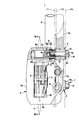
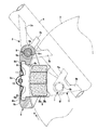
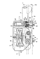
- FIG. 3 is a sectional view taken along line III-III in FIG. 1. It is IV-IV sectional drawing of FIG. It is a front view which shows the attachment state of the disc brake which shows the 2nd form example of this invention.
- FIG. 6 is a sectional view taken along line VI-VI in FIG. 5. It is VII-VII sectional drawing of FIG. It is a principal part cross-sectional side view which similarly shows the attachment state of a disc brake. It is principal part sectional drawing which shows the attachment state of the disc brake which shows the 3rd example of this invention.
- a pin slide type disc brake 1 shown in this embodiment is a brake for a bar handle vehicle such as a motorcycle and rotates together with a wheel (not shown).
- a front fork 4 serving as a vehicle suspension system according to the present invention through a first support leg 3a, a second support leg 3b, and a third support leg 3c at one side of the disk rotor 2.
- the arrow A indicates the direction of rotation of the disc rotor that rotates integrally with the front wheels when the vehicle moves forward, and the disk unloading side and the disk loading side described below are those when the vehicle moves forward.
- the caliper body 8 is composed of the action portion 8a and the reaction portion 8b that are arranged opposite to both sides of the disc rotor 2, and a bridge portion 8c that bridges the outside of the disc rotor 2 and connects them.
- the action portion 8a includes a cylinder hole 8d and a pair of slide pin support portions 8e and 8f, and the reaction portion 8b is provided with a reaction force claw 8g.
- a rectangular ceiling opening 8h is formed in the center of the bridge portion 8c so as to penetrate in and out.
- Torque receiving steps 8i and 8i are disposed on the disk insertion side and the extraction side of the ceiling opening 8h. In the torque receiving step 8i on the disk delivery side, a torque receiving surface 8k that receives the braking torque is formed along the caliper center side surface of the slide pin support 3 on the disk delivery side.
- Each friction pad 9 is formed by joining a lining 9a that is in sliding contact with the side surface of the disk rotor 2 to a metal back plate 9b.
- a hanger pin insertion portion 9c protrudes from the center of the back plate 9b in the radial direction of the disk.
- ear pieces 9d and 9d are provided on both sides of the back plate 9b.
- a hanger pin 10 that passes through the ceiling opening 8h and spans between the action portion 8a and the reaction portion 8b is inserted into the pin insertion portion 9c, and the ear pieces 9d and 9d are locked to the torque receiving steps 8i and 8i.
- the disk rotor 2 is suspended on both sides of the disk rotor 2 so as to be slidable in the disk axis direction, and is elastically supported inward in the disk radial direction by a pad spring 11 that is contracted between the hanger pin 10.
- the cylinder hole 8d is provided in the center of the action portion 8a so as to open to the disk rotor side.
- a cup-shaped piston 12 is liquid-tightly inserted into the cylinder hole 8d, and between the piston 12 and the bottom of the cylinder hole 8d.
- a hydraulic chamber 13 is defined in the interior.
- the slide pin support portions 8e and 8f are provided so as to project from the action portion 8a along the one side surface of the disk rotor 2 toward the disk delivery side and the inner side in the radial direction of the disk.
- the portion 8e extends in the disk axial direction from the action portion side to the reaction portion side, is formed with a long bag-shaped guide hole 8m that opens to the action portion side, and the caliper center side surface of the slide pin support portion 8e is the above-described side surface.
- the torque receiving surface is 8k.
- a guide hole 8n shorter than the guide hole 8m on the disk delivery side is formed in the slide pin support portion 8f on the inner side in the disk radial direction so as to penetrate in the disk axial direction.
- the slide pin mounting portion 3 on the outer periphery side of the disc provided in the front fork 4 includes a mounting hole 3d for the slide pin 6, and the disc is fed out through the first support leg 3a, the second support leg 3b, and the third support leg 3c. Projecting to the outer peripheral side.
- the first support leg 3a extends from the slide pin mounting portion 3 in the direction of the braking torque
- the second support leg 3b extends from the slide pin mounting portion 3 in a direction perpendicular to the first support leg 3a.
- the third support leg 3c protrudes at an intermediate portion between the first support leg 3a and the second support leg 3b.
- the slide pin mounting portion 5 on the inner periphery side of the disk has a mounting hole 5c for the slide pin 7, and protrudes to the disk insertion side and the inner periphery side of the disk via the first support leg 5a and the second support leg 5b. .
- the mounting surfaces 3e and 5d on the disk rotor side pass through the central axis of the front fork 4, and on the outer side of the vehicle body than the parallel surface F1 parallel to the side surface of the disk rotor.
- the mounting surfaces 3f and 5e on the side opposite to the disk rotor are disposed on the same plane F3 parallel to the parallel surface F1, and are arranged on the same plane F2 parallel to the parallel surface F1.
- 5c have the same diameter and the same length.
- the slide pin 6 on the disk delivery side includes a slide pin main body 6a that slides in a guide hole 8m formed in the slide pin support portion 8e, and a hexagon with a flange that attaches the slide pin main body 6a to the slide pin attachment portion 3. It is comprised with the volt
- the slide pin main body 6a includes a slide shaft portion 6c that slides in the guide hole 8m, a first flange portion 6d that contacts the mounting surface 3e on the disk rotor side of the slide pin mounting portion 3, and the first flange portion 6d.
- An open female screw hole 6e is provided.
- the hexagon bolt 6b includes a second flange portion 6h that abuts against the mounting surface 3f on the side opposite to the disk rotor of the slide pin mounting portion 3 between the hexagon head 6f and the shaft portion 6g, and is provided at the tip of the shaft portion 6g. Is formed with a male screw portion 6i.
- the slide pin 7 on the inner circumference side of the disc has the same structure as the slide pin 6 on the outer circumference side of the disc, and is composed of a slide pin main body 7a and a hexagon bolt 7b, and the slide pin main body 7a has a slide shaft portion. 7c, a first flange portion 7d, and a female screw hole 7e.
- the hexagon bolt 7b has a hexagon head portion 7f, a shaft portion 7g, a second flange portion 7h, and a male screw portion 7i.
- the hexagon bolt 6b of the slide pin 6 and the hexagon bolt 7b of the slide pin 7 are formed in the same shape.
- Each slide pin 6, 7 has a hexagon bolt 6 b, 7 b inserted into the mounting hole 3 d, 5 c of the slide pin mounting portion 3, 5 from the opposite side of the disk rotor, and the male screw portion 6 i, protruding from the mounting hole 3 d, 5 c, 7i is screwed into the female screw holes 6e and 7e of the slide pin main bodies 6a and 7a, respectively.
- the slide pin 6 sandwiches the mounting surfaces 3e and 3f of the slide pin mounting portion 3 between the first flange portion 6d and the second flange portion 6h
- the slide pin 7 has the first flange portion 7d and the second flange portion.
- 7h sandwiches the mounting surfaces 5d and 5e of the slide pin mounting portion 5, and the hexagon bolts 6b and 7b and the slide pin bodies 6a and 7a are connected and fixed.
- the slide pin 6 attached to the slide pin mounting portion 3 on the disk delivery side is inserted through the dust boot 14 into the guide hole 8m of the slide pin support portion 8e on the disc delivery side of the caliper body 8.
- the slide pin 7 attached to the slide pin mounting portion 5 on the inner peripheral side of the disc is inserted through the dust boot 15 into the guide hole 8n of the slide pin support portion 8f on the inner peripheral side of the disc of the caliper body 8, and the caliper
- the body 8 is supported so as to be slidable in the disk axial direction.
- the dust boots 14 and 15 have the same shape.
- the mounting surfaces 3f and 5e on the side opposite to the disc rotor of the pair of slide pin mounting portions 3 and 5 formed on the front fork 4, the mounting surfaces 3e and 5d on the disc rotor side, are disposed on the same planes F3 and F2 parallel to the parallel surface F1 outside of the parallel surface F1 passing through the central axis of the front fork 4 and parallel to the side surface of the disc rotor 2, respectively. Since only the mounting holes 3d and 5c having the same diameter and the same length need to be drilled, the slide pin mounting portions 3 and 5 can be easily formed.
- the slide pins 6 and 7 can be attached to the slide pin attachment portions 3 and 5 simply by screwing the male screw portions 6i and 7i of the hexagon bolts 6b and 7b into the female screw holes 6e and 7e of the slide pin bodies 6a and 7a, respectively.
- the slide pins 6 and 7 can be easily attached to the slide pin attachment portions 3 and 5, and the assembling property of the caliper body 8 can be improved.
- the two hexagon bolts 6b and 7b in the same shape and the two dust boots 14 and 15 in the same shape, it is possible to reduce costs and improve work efficiency.
- FIGS. 5 to 9 show other embodiments of the present invention. Components that are the same as those in the first embodiment are denoted by the same reference numerals, and detailed description thereof is omitted.
- the slide pins 6 and 7 of the present embodiment are planar on a part of the outer peripheral surface of the first flange portions 6d and 7d of the slide pin bodies 6a and 7a. Notch portions 6k and 7k are formed.
- the slide pin mounting portions 3 and 5 are each formed in a plate shape spreading in a substantially triangular shape.
- the slide pin mounting portions 3 and 5 are formed on the side of the disk rotor so as to prevent the slide pin main bodies 6 and 7 from rotating. Stop surfaces 3g and 5f are formed on the same plane parallel to the central axis CL1 of the front fork 4, respectively.
- the present embodiment is formed as described above, when the slide pins 6 and 7 are mounted on the slide pin mounting portions 3 and 5, the notches 6k and 7k are brought into contact with the rotation stop surfaces 3g and 5f.
- the slide pin bodies 6a and 7a are prevented from rotating, and the hexagon bolts 6b and 7b can be fastened well.
- the slide pin main bodies 6a, 7a and the hexagon bolts 6b, 7b are connected and fixed, the notch portions 6k, 7k of the slide pin main bodies 6a, 7a become the hexagon mounting bolt 6b by the fastening torque of the hexagon bolts 6b, 7b.
- 7b is in contact with the anti-rotation surface while being displaced toward the fastening rotation direction R1, and the slide pins 6 and 7 are attached to the non-anti-rotation surface. Since they are displaced in the same direction, the distance between the pitches of the slide pins 6 and 7 does not change, and the drag of the friction pad 9 can be prevented.
- FIG. 9 shows a third embodiment of the present invention, and the slide pin mounting portions 3 and 5 of the present embodiment are each formed in a plate shape spreading in a substantially triangular shape, similar to the second embodiment.
- the pin mounting portions 3 and 5 notches 6k and 7k are formed in the first flange portions 6d and 7d of the slide pin main bodies 6a and 7a.
- the rotation stop surfaces 3h and 5g formed on the slide pin mounting portions 3 and 5 are on one side in the fastening rotation direction R1 of the hexagon bolts 6b and 7b when the slide pin bodies 6a and 7a and the hexagon bolts 6b and 7b are connected and fixed. Are formed in parallel to each other.
- slide pin 6a, 7a ... slide pin body, 6b, 7b ... hexagon bolt, 6c, 7c ... sliding shaft, 6d, 7d ... first flange, 6e, 7e ... female screw hole, 6f, 7f ... hexagon head, 6g, 7g ... shaft, 6h, 7h ... second flange, 6i , 7i ... male screw part, 6k, 7k ... notch part, ... caliper body, 8a ... action part, 8b ... reaction part, 8c ... bridge part, 8d ... cylinder hole, 8e, 8f ... slide pin support part, 8g ... reaction force claw, 8h ... ceiling opening part, 8i ... torque step Part, 8k ...
Landscapes
- Engineering & Computer Science (AREA)
- General Engineering & Computer Science (AREA)
- Mechanical Engineering (AREA)
- Braking Arrangements (AREA)
Abstract
Description
Claims (5)
- ディスクロータの外周を跨いで配設されるキャリパボディの作用部と反作用部との間にディスクロータを挟んで一対の摩擦パッドを対向配置し、前記作用部にスライドピンのガイド孔を備えた一対のスライドピン支持部を形成し、該スライドピン支持部に挿通したスライドピンを、車両懸架装置に設けた一対のスライドピン取付部に装着して前記キャリパボディをディスク軸方向にスライド可能に支持する車両用ディスクブレーキのキャリパボディ支持構造であって、前記スライドピンは、前記ガイド孔を摺動するスライドピン本体と、該スライドピン本体を前記スライドピン取付部に取り付けるピン取付ボルトとで構成され、前記一対のスライドピン取付部の反ディスクロータ側の取付面は、前記車両懸架装置の中心軸を通り、且つ、前記ディスクロータの側面と平行な平行面よりも車体外側で、該平行面と平行な同一平面上に配置される、車両用ディスクブレーキのキャリパボディ支持構造。
- 前記スライドピン本体に前記スライドピン取付部のディスクロータ側の取付面に当接する第1フランジ部を、前記ピン取付ボルトに前記スライドピン取付部の反ディスクロータ側の取付面に当接する第2フランジ部をそれぞれ設け、両スライドピン取付部に同径の装着孔をそれぞれ穿設し、各装着孔に挿通したピン取付ボルトの先端側に前記スライドピン本体をそれぞれ締結し、前記第1フランジ部と第2フランジ部とで前記スライドピン取付部を挟持して、前記スライドピン本体とピン取付ボルトとを連結固定する、請求項1記載の車両用ディスクブレーキのキャリパボディ支持構造。
- 前記一対のスライドピン取付部にスライドピン本体をそれぞれ取り付ける一対のピン取付ボルトは同一形状である、請求項1又は2記載の車両用ディスクブレーキのキャリパボディ支持構造。
- 各スライドピン本体に設けた前記第1フランジ部の外周面の一部に、切欠部をそれぞれ形成すると共に、各スライドピン取付部に、前記切欠部に当接して前記スライドピン本体を回り止めする回止め面をそれぞれ形成し、該各回止め面は同一平面上にある、請求項1乃至3のいずれか1項記載のキャリパボディ支持構造。
- 各スライドピン本体に設けた前記第1フランジ部の外周面の一部に、切欠部をそれぞれ形成すると共に、各スライドピン取付部に、前記切欠部に当接して前記スライドピン本体を回り止めする回止め面をそれぞれ形成し、各回止め面は、前記スライドピン本体と前記ピン取付ボルトとを連結固定する際の前記ピン取付ボルトの締結回転方向の一方側に、互いに平行に形成される、請求項1乃至3のいずれか1項記載のキャリパボディ支持構造。
Priority Applications (2)
| Application Number | Priority Date | Filing Date | Title |
|---|---|---|---|
| JP2011515998A JP5587876B2 (ja) | 2009-05-27 | 2010-05-21 | 車両用ディスクブレーキのキャリパボディ支持構造 |
| CN201080023083.6A CN102449342B (zh) | 2009-05-27 | 2010-05-21 | 车辆用盘式制动器的钳体支承结构 |
Applications Claiming Priority (2)
| Application Number | Priority Date | Filing Date | Title |
|---|---|---|---|
| JP2009127486 | 2009-05-27 | ||
| JP2009-127486 | 2009-05-27 |
Publications (1)
| Publication Number | Publication Date |
|---|---|
| WO2010137520A1 true WO2010137520A1 (ja) | 2010-12-02 |
Family
ID=43222630
Family Applications (1)
| Application Number | Title | Priority Date | Filing Date |
|---|---|---|---|
| PCT/JP2010/058585 Ceased WO2010137520A1 (ja) | 2009-05-27 | 2010-05-21 | 車両用ディスクブレーキのキャリパボディ支持構造 |
Country Status (4)
| Country | Link |
|---|---|
| JP (1) | JP5587876B2 (ja) |
| CN (2) | CN102449342B (ja) |
| TW (1) | TWI457255B (ja) |
| WO (1) | WO2010137520A1 (ja) |
Families Citing this family (3)
| Publication number | Priority date | Publication date | Assignee | Title |
|---|---|---|---|---|
| CN106218604A (zh) * | 2016-08-25 | 2016-12-14 | 王新平 | 一种两轮机动车液压制动器安装机构 |
| US10604208B2 (en) | 2017-03-15 | 2020-03-31 | Shimano Inc. | Bicycle suspension tube and bicycle suspension fork |
| CN111365389A (zh) * | 2020-03-23 | 2020-07-03 | 兰溪奥通摩擦材料有限公司 | 一种刹车装置上便于更换刹车盘的插块 |
Citations (6)
| Publication number | Priority date | Publication date | Assignee | Title |
|---|---|---|---|---|
| JPS55165893U (ja) * | 1979-05-17 | 1980-11-28 | ||
| JPS5716635U (ja) * | 1980-07-03 | 1982-01-28 | ||
| JPS59191434U (ja) * | 1983-06-08 | 1984-12-19 | 住友電気工業株式会社 | 浮動型デイスクブレ−キ |
| JPH07310768A (ja) * | 1994-05-17 | 1995-11-28 | Nissin Kogyo Kk | ピンスライド型車両用ディスクブレーキの摺動ピン取付け構造 |
| JP2003254360A (ja) * | 2002-03-04 | 2003-09-10 | Akebono Brake Ind Co Ltd | フローティングタイプのディスクブレーキ |
| JP2008138737A (ja) * | 2006-11-30 | 2008-06-19 | Hitachi Ltd | ディスクブレーキ |
Family Cites Families (4)
| Publication number | Priority date | Publication date | Assignee | Title |
|---|---|---|---|---|
| JPS51109642A (en) * | 1975-03-20 | 1976-09-28 | Tokico Ltd | Nirinshayodeisukubureeki |
| JPH08169207A (ja) * | 1994-08-18 | 1996-07-02 | Bridgestone Metalpha Kk | 空気入りラジアルタイヤ |
| JP2002206576A (ja) * | 2001-01-12 | 2002-07-26 | Nissin Kogyo Co Ltd | 機械式車両用ディスクブレーキ |
| JP4521453B2 (ja) * | 2007-11-26 | 2010-08-11 | 日信工業株式会社 | 車両用ディスクブレーキのキャリパボディ支持構造 |
-
2010
- 2010-05-21 JP JP2011515998A patent/JP5587876B2/ja not_active Expired - Fee Related
- 2010-05-21 WO PCT/JP2010/058585 patent/WO2010137520A1/ja not_active Ceased
- 2010-05-21 CN CN201080023083.6A patent/CN102449342B/zh not_active Expired - Fee Related
- 2010-05-21 CN CN201510487721.4A patent/CN105134831B/zh not_active Expired - Fee Related
- 2010-05-26 TW TW099116787A patent/TWI457255B/zh not_active IP Right Cessation
Patent Citations (6)
| Publication number | Priority date | Publication date | Assignee | Title |
|---|---|---|---|---|
| JPS55165893U (ja) * | 1979-05-17 | 1980-11-28 | ||
| JPS5716635U (ja) * | 1980-07-03 | 1982-01-28 | ||
| JPS59191434U (ja) * | 1983-06-08 | 1984-12-19 | 住友電気工業株式会社 | 浮動型デイスクブレ−キ |
| JPH07310768A (ja) * | 1994-05-17 | 1995-11-28 | Nissin Kogyo Kk | ピンスライド型車両用ディスクブレーキの摺動ピン取付け構造 |
| JP2003254360A (ja) * | 2002-03-04 | 2003-09-10 | Akebono Brake Ind Co Ltd | フローティングタイプのディスクブレーキ |
| JP2008138737A (ja) * | 2006-11-30 | 2008-06-19 | Hitachi Ltd | ディスクブレーキ |
Also Published As
| Publication number | Publication date |
|---|---|
| CN102449342A (zh) | 2012-05-09 |
| CN105134831A (zh) | 2015-12-09 |
| JP5587876B2 (ja) | 2014-09-10 |
| CN105134831B (zh) | 2017-08-04 |
| CN102449342B (zh) | 2016-01-20 |
| TW201103789A (en) | 2011-02-01 |
| JPWO2010137520A1 (ja) | 2012-11-15 |
| TWI457255B (zh) | 2014-10-21 |
Similar Documents
| Publication | Publication Date | Title |
|---|---|---|
| JP7075848B2 (ja) | ディスクブレーキ | |
| US20180106310A1 (en) | Disc brake device | |
| JP2006057718A (ja) | フローティングキャリパ型ディスクブレーキ | |
| JP2014190478A (ja) | ディスクブレーキ装置 | |
| JP5587876B2 (ja) | 車両用ディスクブレーキのキャリパボディ支持構造 | |
| JP5832473B2 (ja) | 車両用ディスクブレーキのキャリパボディ | |
| JP6928564B2 (ja) | 車両用ディスクブレーキ | |
| JP5879032B2 (ja) | ディスクブレーキ | |
| JP4521453B2 (ja) | 車両用ディスクブレーキのキャリパボディ支持構造 | |
| JP2015055260A (ja) | 車両用ディスクブレーキ | |
| JP2009133356A (ja) | フローティングキャリパ型ディスクブレーキ | |
| JP5510144B2 (ja) | ディスクブレーキ | |
| JP4718422B2 (ja) | ディスクブレーキ | |
| JP4839272B2 (ja) | ピンスライド型車両用ディスクブレーキ | |
| JP5087645B2 (ja) | ピンレールキャリパを有するディスクブレーキ | |
| JP2013190035A (ja) | 車両用ディスクブレーキ | |
| JP5603797B2 (ja) | 車両用ディスクブレーキ | |
| JP4970345B2 (ja) | ディスクブレーキ | |
| JP4590427B2 (ja) | ピンスライド型車両用ディスクブレーキ | |
| CA2502525A1 (en) | Disc brake for a vehicle | |
| JP4288197B2 (ja) | 車両用ディスクブレーキ | |
| JP6144614B2 (ja) | 車両用ディスクブレーキ | |
| JP6027834B2 (ja) | ディスクブレーキ | |
| JP2011033130A (ja) | ディスクブレーキ | |
| JP2009264462A (ja) | ディスクブレーキ及びその製造方法 |
Legal Events
| Date | Code | Title | Description |
|---|---|---|---|
| WWE | Wipo information: entry into national phase |
Ref document number: 201080023083.6 Country of ref document: CN |
|
| 121 | Ep: the epo has been informed by wipo that ep was designated in this application |
Ref document number: 10780475 Country of ref document: EP Kind code of ref document: A1 |
|
| WWE | Wipo information: entry into national phase |
Ref document number: 2011515998 Country of ref document: JP |
|
| WWE | Wipo information: entry into national phase |
Ref document number: 8960/DELNP/2011 Country of ref document: IN |
|
| NENP | Non-entry into the national phase |
Ref country code: DE |
|
| 122 | Ep: pct application non-entry in european phase |
Ref document number: 10780475 Country of ref document: EP Kind code of ref document: A1 |