WO2010137401A1 - ヒートポンプ装置 - Google Patents
ヒートポンプ装置 Download PDFInfo
- Publication number
- WO2010137401A1 WO2010137401A1 PCT/JP2010/055686 JP2010055686W WO2010137401A1 WO 2010137401 A1 WO2010137401 A1 WO 2010137401A1 JP 2010055686 W JP2010055686 W JP 2010055686W WO 2010137401 A1 WO2010137401 A1 WO 2010137401A1
- Authority
- WO
- WIPO (PCT)
- Prior art keywords
- heat exchanger
- heat
- refrigerant
- water
- compressor
- Prior art date
Links
Images


Classifications
-
- F—MECHANICAL ENGINEERING; LIGHTING; HEATING; WEAPONS; BLASTING
- F25—REFRIGERATION OR COOLING; COMBINED HEATING AND REFRIGERATION SYSTEMS; HEAT PUMP SYSTEMS; MANUFACTURE OR STORAGE OF ICE; LIQUEFACTION SOLIDIFICATION OF GASES
- F25B—REFRIGERATION MACHINES, PLANTS OR SYSTEMS; COMBINED HEATING AND REFRIGERATION SYSTEMS; HEAT PUMP SYSTEMS
- F25B6/00—Compression machines, plants or systems, with several condenser circuits
- F25B6/04—Compression machines, plants or systems, with several condenser circuits arranged in series
-
- F—MECHANICAL ENGINEERING; LIGHTING; HEATING; WEAPONS; BLASTING
- F24—HEATING; RANGES; VENTILATING
- F24H—FLUID HEATERS, e.g. WATER OR AIR HEATERS, HAVING HEAT-GENERATING MEANS, e.g. HEAT PUMPS, IN GENERAL
- F24H4/00—Fluid heaters characterised by the use of heat pumps
- F24H4/02—Water heaters
-
- F—MECHANICAL ENGINEERING; LIGHTING; HEATING; WEAPONS; BLASTING
- F25—REFRIGERATION OR COOLING; COMBINED HEATING AND REFRIGERATION SYSTEMS; HEAT PUMP SYSTEMS; MANUFACTURE OR STORAGE OF ICE; LIQUEFACTION SOLIDIFICATION OF GASES
- F25B—REFRIGERATION MACHINES, PLANTS OR SYSTEMS; COMBINED HEATING AND REFRIGERATION SYSTEMS; HEAT PUMP SYSTEMS
- F25B30/00—Heat pumps
- F25B30/02—Heat pumps of the compression type
-
- F—MECHANICAL ENGINEERING; LIGHTING; HEATING; WEAPONS; BLASTING
- F25—REFRIGERATION OR COOLING; COMBINED HEATING AND REFRIGERATION SYSTEMS; HEAT PUMP SYSTEMS; MANUFACTURE OR STORAGE OF ICE; LIQUEFACTION SOLIDIFICATION OF GASES
- F25B—REFRIGERATION MACHINES, PLANTS OR SYSTEMS; COMBINED HEATING AND REFRIGERATION SYSTEMS; HEAT PUMP SYSTEMS
- F25B2339/00—Details of evaporators; Details of condensers
- F25B2339/04—Details of condensers
- F25B2339/047—Water-cooled condensers
-
- F—MECHANICAL ENGINEERING; LIGHTING; HEATING; WEAPONS; BLASTING
- F25—REFRIGERATION OR COOLING; COMBINED HEATING AND REFRIGERATION SYSTEMS; HEAT PUMP SYSTEMS; MANUFACTURE OR STORAGE OF ICE; LIQUEFACTION SOLIDIFICATION OF GASES
- F25B—REFRIGERATION MACHINES, PLANTS OR SYSTEMS; COMBINED HEATING AND REFRIGERATION SYSTEMS; HEAT PUMP SYSTEMS
- F25B2400/00—General features or devices for refrigeration machines, plants or systems, combined heating and refrigeration systems or heat-pump systems, i.e. not limited to a particular subgroup of F25B
- F25B2400/07—Details of compressors or related parts
- F25B2400/075—Details of compressors or related parts with parallel compressors
-
- F—MECHANICAL ENGINEERING; LIGHTING; HEATING; WEAPONS; BLASTING
- F25—REFRIGERATION OR COOLING; COMBINED HEATING AND REFRIGERATION SYSTEMS; HEAT PUMP SYSTEMS; MANUFACTURE OR STORAGE OF ICE; LIQUEFACTION SOLIDIFICATION OF GASES
- F25B—REFRIGERATION MACHINES, PLANTS OR SYSTEMS; COMBINED HEATING AND REFRIGERATION SYSTEMS; HEAT PUMP SYSTEMS
- F25B2400/00—General features or devices for refrigeration machines, plants or systems, combined heating and refrigeration systems or heat-pump systems, i.e. not limited to a particular subgroup of F25B
- F25B2400/13—Economisers
-
- F—MECHANICAL ENGINEERING; LIGHTING; HEATING; WEAPONS; BLASTING
- F25—REFRIGERATION OR COOLING; COMBINED HEATING AND REFRIGERATION SYSTEMS; HEAT PUMP SYSTEMS; MANUFACTURE OR STORAGE OF ICE; LIQUEFACTION SOLIDIFICATION OF GASES
- F25B—REFRIGERATION MACHINES, PLANTS OR SYSTEMS; COMBINED HEATING AND REFRIGERATION SYSTEMS; HEAT PUMP SYSTEMS
- F25B2500/00—Problems to be solved
- F25B2500/31—Low ambient temperatures
-
- F—MECHANICAL ENGINEERING; LIGHTING; HEATING; WEAPONS; BLASTING
- F28—HEAT EXCHANGE IN GENERAL
- F28D—HEAT-EXCHANGE APPARATUS, NOT PROVIDED FOR IN ANOTHER SUBCLASS, IN WHICH THE HEAT-EXCHANGE MEDIA DO NOT COME INTO DIRECT CONTACT
- F28D9/00—Heat-exchange apparatus having stationary plate-like or laminated conduit assemblies for both heat-exchange media, the media being in contact with different sides of a conduit wall
- F28D9/0031—Heat-exchange apparatus having stationary plate-like or laminated conduit assemblies for both heat-exchange media, the media being in contact with different sides of a conduit wall the conduits for one heat-exchange medium being formed by paired plates touching each other
- F28D9/0043—Heat-exchange apparatus having stationary plate-like or laminated conduit assemblies for both heat-exchange media, the media being in contact with different sides of a conduit wall the conduits for one heat-exchange medium being formed by paired plates touching each other the plates having openings therein for circulation of at least one heat-exchange medium from one conduit to another
- F28D9/005—Heat-exchange apparatus having stationary plate-like or laminated conduit assemblies for both heat-exchange media, the media being in contact with different sides of a conduit wall the conduits for one heat-exchange medium being formed by paired plates touching each other the plates having openings therein for circulation of at least one heat-exchange medium from one conduit to another the plates having openings therein for both heat-exchange media
Definitions
- the present invention relates to a heat pump apparatus such as a heat pump type hot water supply apparatus, and more particularly to a heat pump apparatus that can obtain a large heating capability even at a low outside air temperature and that can efficiently discharge hot water at a high temperature.
- a method for efficiently discharging hot water a method is known in which a binary compression cycle is configured and water is circulated in series through a low-stage condenser and a high-stage condenser. (For example, refer to Patent Document 2).
- the inlet refrigerant enthalpy of the outdoor heat exchanger serving as an evaporator does not change regardless of whether the high-stage compressor is operated or stopped, so that heat can be collected from outside air.
- the amount of heat is determined by the maximum capacity of the low stage compressor. Therefore, the high stage side compressor input is directly transferred to the condensing capacity, and in terms of heating efficiency, heating in the high stage side cycle is equivalent to heating by the electric heater, and it is difficult to say that the efficiency is high.
- An object of the present invention is to solve the above-described problems, and to provide a heat pump device that efficiently performs high-temperature tapping while increasing the condensing capacity at a low outside air temperature to the maximum. Objective.
- the heat pump device is A first refrigeration cycle configured by sequentially connecting a first compressor, a first heat exchanger, an internal heat exchanger, a first decompression device, and an evaporator; Branching from between the first heat exchanger and the first pressure reducing device, a second pressure reducing device, the internal heat exchanger, a second compressor, a third pressure reducing device are sequentially connected, A second refrigeration cycle that joins again between the first compressor and the first heat exchanger is provided.
- the second refrigeration cycle further includes a heat radiating means between the second compressor and the third decompression device.
- the heat dissipating means is a second heat exchanger, and the fluid after heat exchange with the refrigerant flowing through the first refrigeration cycle in the first heat exchanger flows to the second heat exchanger.
- the second heat exchanger is provided so as to exchange heat with the refrigerant flowing through the second refrigeration cycle.
- the heat pump device further includes: A control unit is provided that adjusts the opening of the third decompressor so that the condensation pressure of the second heat exchanger is higher than the condensation pressure of the first heat exchanger.
- the control unit controls the second compressor so that an evaporation pressure in the second refrigeration cycle is higher than an evaporation pressure in the first refrigeration cycle.
- the first heat exchanger is a water-refrigerant heat exchanger for exchanging heat between water and a refrigerant flowing through the first refrigeration cycle;
- the second heat exchanger is a water-refrigerant heat exchanger that exchanges heat between water and a refrigerant flowing through the second refrigeration cycle.
- At least one of the first heat exchanger and the second heat exchanger is a plate stacked heat exchanger.
- the heat dissipating means is constituted by a pipe disposed near the lower end of the evaporator.
- the second refrigeration cycle further includes a plurality of heat dissipating means arranged in parallel between the second compressor and the third pressure reducing device, And a heat dissipating means switching device for switching to which of the plurality of heat dissipating means the refrigerant flowing through the second refrigeration circuit is provided.
- the heat pump device expands the enthalpy difference of the evaporator by the heat recovery operation by the second compressor and the internal heat exchanger without using an expensive injection compressor, the second compressor In addition to obtaining a large heating capacity equal to or greater than the electrical input, an increase in the amount of heat collected from the outside air makes it possible to perform a hot water supply operation in which the COP is higher than the heating capacity increasing effect of the electric heater.
- the heating capacity is maximized by performing adjustment to maximize the electric input of the second compressor. Can do.
- circulated to a 1st heat exchanger becomes the sum total of a 1st compressor and a 2nd compressor, and a refrigerant
- a second heat exchanger is provided between the second compressor and the third decompression device so that different condensation temperatures are generated in the first refrigeration cycle and the second refrigeration cycle. Therefore, it is possible to perform a heating operation with high efficiency even when high-temperature water is required.
- FIG. 5 shows the first embodiment, and is a refrigerant circuit diagram of a heat pump hot water supply apparatus.
- FIG. 3 is a diagram showing the first embodiment, and is a perspective view showing an internal configuration of a first water-refrigerant heat exchanger 2 (plate stacked heat exchanger).
- FIG. 5 is a diagram illustrating the first embodiment and is a Ph diagram illustrating the operation of the refrigeration cycle.
- FIG. 5 shows the first embodiment, and is a refrigerant circuit diagram of a heat pump type hot water supply apparatus when the heat dissipating means is a water-refrigerant heat exchanger.
- FIG. 3 is a diagram showing the first embodiment, and is a perspective view showing an internal configuration of a first water-refrigerant heat exchanger 2 (plate stacked heat exchanger).
- FIG. 5 is a diagram illustrating the first embodiment and is a Ph diagram illustrating the operation of the refrigeration cycle.
- FIG. 5 shows the first embodiment, and is a refrigerant circuit diagram of
- FIG. 5 shows the first embodiment, and is a Ph diagram showing the refrigeration cycle operation when the heat dissipating means is a water-refrigerant heat exchanger.
- FIG. 5 shows the first embodiment, and shows a temperature change process inside the water-refrigerant heat exchanger when the heat radiating means is a water-refrigerant heat exchanger.
- FIG. 5 shows the first embodiment and is a refrigerant circuit configuration diagram in the case where the heat dissipating means is a freeze prevention heater.
- FIG. 5 shows the first embodiment, and is a Ph diagram showing the refrigeration cycle operation when the heat dissipating means is a freeze prevention heater.
- FIG. 1 to 7 are diagrams showing Embodiment 1
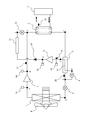
- FIG. 1 is a refrigerant circuit diagram of a heat pump type hot water supply apparatus
- FIG. 2 is an internal view of a first water-refrigerant heat exchanger 2 (plate stacked heat exchanger).
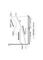
- FIG. 3 is a Ph diagram showing the operation of the refrigeration cycle
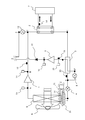
- FIG. 4 is a refrigerant circuit diagram of a heat pump hot water supply apparatus when the heat radiating means is a water-refrigerant heat exchanger
- FIG. 5 is a heat radiating means.
- Fig. 6 is a Ph diagram showing the refrigeration cycle operation when the water-refrigerant heat exchanger is used
- Fig. 6 is a Ph diagram showing the refrigeration cycle operation when the water-refrigerant heat exchanger is used
- FIG. 6 is a diagram showing the temperature change process inside the water-refrigerant heat exchanger when the heat radiating means is a water-refrigerant heat exchanger.
- 7 is a refrigerant circuit configuration diagram in the case where the heat dissipating means is an anti-freeze heater
- FIG. 8 is a Ph diagram showing the refrigeration cycle operation in the case where the heat dissipating means is an anti-freeze heater.
- the refrigerant circuit of the heat pump hot water supply apparatus shown in FIG. 1 includes a first refrigeration cycle and a second refrigeration cycle.
- the first refrigeration cycle includes a main compressor 1 (first compressor), a first water-refrigerant heat exchanger 2 (first heat exchanger), an internal heat exchanger 3, and an electric expansion valve 4 (first 1) and an air heat exchanger 5 (evaporator) for collecting heat from outside air are sequentially connected.
- the second refrigeration cycle branches from between the internal heat exchanger 3 and the electric expansion valve 4 of the first refrigeration cycle, and the main compressor 1 and the first water-refrigerant heat exchanger of the first refrigeration cycle. 2 and join. Note that the second refrigeration cycle may be branched from another position as long as it is between the first water-refrigerant heat exchanger 2 and the electric expansion valve 4.
- the second refrigeration cycle is branched from between the internal heat exchanger 3 and the electric expansion valve 4 of the first refrigeration cycle, and the branch expansion valve 8 (second decompression device) and the suction pipe of the sub compressor 9 22 (through the internal heat exchanger 3), sub-compressor 9 (second compressor), check valve 10, sub-heat radiating means 11 (heat radiating means), merging expansion valve 12 (third pressure reducing device) And are joined between the main compressor 1 and the first water-refrigerant heat exchanger 2 in the first refrigeration cycle.
- R410A is sealed as a refrigerant in the first refrigeration cycle and the second refrigeration cycle.
- the main compressor 1 is provided with a pressure sensor 13 for detecting the suction pressure and a pressure sensor 14 for detecting the discharge pressure.
- the sub-compressor 9 is provided with a pressure sensor 15 for detecting the suction pressure and a pressure sensor 16 for detecting the discharge pressure.
- a temperature sensor 17 that detects the discharge temperature of the main compressor 1, a temperature sensor 18 that detects the feed water temperature at the outlet of the first water-refrigerant heat exchanger 2, and a temperature sensor that detects the temperature of the intake refrigerant of the sub compressor 9 19.
- a temperature sensor 20 for detecting the temperature of the refrigerant at the outlet of the internal heat exchanger 3 of the first refrigeration cycle is provided.
- a control unit (not shown) controls the operation of the heat pump hot water supply apparatus based on information from the pressure sensors 13 to 16 and the temperature sensors 17 to 20.
- the control unit is composed of a microcomputer (microcomputer) in which a predetermined program is incorporated.
- microcomputer microcomputer
- the subject in the following various controls is the control unit, but the word “control unit” is not described.
- the air heat exchanger 5 is provided with a blower 6 that adjusts the amount of heat collected from outside air.
- a hot water supply tank 7 serving as a hot water supply load is connected to the first water-refrigerant heat exchanger 2, and water is circulated as a heat medium.
- the arrow of FIG. 1 has shown the flow of the water which is a heat medium.
- the first water-refrigerant heat exchanger 2 As the first water-refrigerant heat exchanger 2, a known plate-stacked heat exchanger is used. The internal configuration of the first water-refrigerant heat exchanger 2 (plate stacked heat exchanger) will be described briefly with reference to FIG. In FIG. 2, the cylindrical body which comprises an outer periphery cover is abbreviate
- a refrigerant pipe connection port 2a is provided in one outermost plate 2d. Further, a water pipe connection port 2b is provided on the other outermost plate 2d.
- a plurality of wave-shaped heat transfer plates 2c are arranged side by side between the pair of outermost plates 2d. Between the heat transfer plates 2c, refrigerant flow paths 2e and water flow paths 2f are alternately formed. And the refrigerant
- FIG. 3 is a Ph diagram (also referred to as a Mollier diagram) showing the operation of the refrigeration cycle during hot water supply operation.
- the horizontal axis represents specific enthalpy [kJ / kg] and the vertical axis represents refrigerant pressure [MPa].
- the first refrigeration cycle operates as indicated by the solid line A ⁇ B ⁇ C ⁇ D ⁇ E ⁇ A.
- the second refrigeration cycle operates as indicated by broken lines G ⁇ H ⁇ I ⁇ C ⁇ D ⁇ F ⁇ G.
- Low pressure gas refrigerant (state A) is sucked into the main compressor 1; (2) The low-pressure gas refrigerant (state A) is compressed by the main compressor 1 and discharged as a high-temperature and high-pressure gas refrigerant (state B); (3) The first water-refrigerant heat exchanger 2 dissipates heat into water and condenses to become a high-pressure liquid refrigerant (state C); (4) The internal heat exchanger 3 exchanges heat with the branched refrigerant of the second refrigeration cycle to become a supercooled liquid (state D); (5) The electric expansion valve 4 is depressurized to the first low pressure and becomes a low-pressure two-phase refrigerant (state E); (6) The air heat exchanger 5 collects heat from the outside air and evaporates to become a low-pressure gas refrigerant (state A) again.
- the opening degree of the electric expansion valve 4 is determined based on the operation characteristics of the main compressor 1 that are known in advance, the suction pressure detected by the pressure sensor 13, and the discharge pressure detected by the pressure sensor 14.
- the target discharge temperature at which the suction refrigerant (state A) sucked in is predicted to be saturated steam is adjusted so that the actual discharge temperature detected by the temperature sensor 17 matches the predicted target discharge temperature.
- the rotation speed (operating capacity) of the main compressor 1 is adjusted so that the feed water temperature detected by the temperature sensor 18 becomes a target value, for example, 45 ° C. By operating in this way, hot water heated to a predetermined temperature is supplied to the hot water supply tank 7 serving as a hot water supply load.
- the target water supply temperature (for example, 45 ° C.) may not be adjusted.
- a scroll compressor of about 5 horsepower is used for the main compressor 1
- a rotary compressor of about 2 horsepower is used for the sub compressor 9.
- the second refrigeration cycle is operated.
- a part of the refrigerant is branched from the outlet of the internal heat exchanger 3 (state D), and the pressure is reduced to the second low pressure (higher than the first low pressure) by the shunt expansion valve 8.
- the second low-pressure refrigerant (state F) is heated by the high-pressure liquid refrigerant (state C) in the internal heat exchanger 3 when the suction pipe 22 passes through the internal heat exchanger 3, and is then gas refrigerant (state G). ) And is sucked into the sub compressor 9.
- the second high-pressure gas refrigerant (state H) boosted by the sub-compressor 9 is decompressed by the merging expansion valve 12 and merges with the discharge refrigerant (state B) of the main compressor 1 to become the state I and become the first It flows into the water-refrigerant heat exchanger 2. Thereafter, the first water-refrigerant heat exchanger 2 dissipates heat into water and condenses to become high-pressure liquid refrigerant (state C), and the internal heat exchanger 3 exchanges heat with the branched refrigerant of the second refrigeration cycle. It becomes a supercooled liquid (state D).
- the opening degree of the diversion expansion valve 8 is adjusted so that the state of the refrigerant (state G) of the sub-compressor 9 detected by the temperature sensor 19 and the pressure sensor 15 is saturated steam or slightly overheated. Is done.
- the sub-compressor 9 may be a constant speed compressor. However, when the sub-compressor 9 is an inverter driven compressor capable of adjusting the rotation speed, the sub-compressor 9 is set so that the suction pressure detected by the pressure sensor 15 becomes a predetermined value. 9 is adjusted.
- the opening of the merging expansion valve 12 can manipulate the discharge pressure of the sub-compressor 9 detected by the pressure sensor 16, the discharge pressure of the sub-compressor 9 satisfies the required heating capacity. adjust.
- the heat pump type hot water supply apparatus dissipates heat to the water by the first water-refrigerant heat exchanger 2 by operating the second refrigeration cycle so that the heating capacity is maximized.
- the condensed high-pressure liquid refrigerant (state C) exchanges heat with the branched refrigerant of the second refrigeration cycle in the internal heat exchanger 3 to become supercooled liquid (state D), and the difference between the state E and the state A increases. As a result, the amount of heat collected from the outside air is increased, and the operating efficiency of the heating operation is improved.
- the input of the sub compressor 9 is also added to the total amount of heat of condensation, increasing the maximum heating capacity.
- the basic refrigeration cycle operation and operation control are the same as when nothing is connected to the sub-heat dissipating means 11 described above, but here the sub-heat dissipating means 11 is connected to the second water-refrigerant heat exchanger 23.
- the circulating water from the hot water supply tank 7 is passed through the first water-refrigerant heat exchanger 2 on the first refrigeration cycle side to the second water-refrigerant heat exchanger 23.
- the high-temperature and high-pressure gas refrigerant discharged from the sub-compressor 9 heats the water again in the second water-refrigerant heat exchanger 23, and the circulating water becomes higher in temperature and returns to the hot water supply tank 7.
- the refrigerant (state J) exiting the second water-refrigerant heat exchanger 23 is decompressed by the merging expansion valve 12 and merged with the refrigerant discharged in the main compressor 1 (state B) (state I), and then the first The water-refrigerant heat exchanger 2 is circulated.
- the main compressor 1 In the situation where the second refrigeration cycle is operated, the main compressor 1 is already operating at maximum capacity. Further, in the merging expansion valve 12, when a high temperature water of 50 ° C. or higher is required, a target discharge pressure that enables hot water discharge at the water temperature is set, and the target discharge pressure set by the discharge pressure of the sub compressor 9 is set. The opening degree is adjusted so as to be a pressure. In the sub-compressor 9, the rotation speed is adjusted so as to achieve a heating capacity capable of realizing the target hot water temperature detected by the temperature sensor 18.
- the discharge pressure of the sub-compressor 9 (the output value of the pressure sensor 16) is substantially determined by the water temperature flowing from the first water-refrigerant heat exchanger 2 into the second water-refrigerant heat exchanger 23. Therefore, the opening degree of the merging expansion valve 12 may be adjusted so that the degree of supercooling at the outlet of the second water-refrigerant heat exchanger 23 (state J) is 1 to 2 [K]. In this case, the suction pressure (output value of the pressure sensor 15) and the input of the sub compressor 9 change depending on the rotation speed of the sub compressor 9. Therefore, since the heating capacity in the second water-refrigerant heat exchanger 23 also changes with the rotation speed of the sub-compressor 9, the outlet water temperature can be controlled to be a set value.
- FIG. 6 shows the process of temperature change between water and refrigerant in the first water-refrigerant heat exchanger 2 and the second water-refrigerant heat exchanger 23.
- the circulating water side passes through the first water-refrigerant heat exchanger 2 and the second water-refrigerant heat exchanger 23 in series, and the temperature rises almost linearly from the inlet to the outlet.
- the condensing pressure of the second water-refrigerant heat exchanger 23 is set higher than that of the first water-refrigerant heat exchanger 2, and each has a different condensing temperature.
- the temperature difference with the refrigerant can be made smaller with respect to the rising water temperature than when the temperature is raised at the temperature.
- the temperature can be raised at a lower condensation temperature on the low water temperature side, and the temperature can be raised at a higher condensation temperature on the high water temperature side, so that the temperature difference between water and the refrigerant does not become larger than necessary. Therefore, the temperature can be raised with high efficiency with respect to the same hot water temperature, and the coefficient of performance (COP) of the refrigeration cycle can be improved.
- COP coefficient of performance
- the condensation temperature needs to be set to a level higher than that, but the refrigerant circuit of FIG. 4 in which the sub-heat dissipating means 11 serves as the second water-refrigerant heat exchanger 23.
- the second water-refrigerant heat exchanger 23 side that is, the second refrigeration cycle side needs to have the high condensation temperature, and the entire system can be operated with high efficiency. Since it is not necessary to collect heat, the second refrigeration cycle can be operated at a relatively low pressure. Therefore, even when the outside air is extremely low, it is difficult to achieve a high compression ratio, and operation restrictions such as an abnormal increase in discharge temperature are unlikely to occur. That is, reliability can be improved even under severe operating conditions by controlling the low pressure of the second refrigeration cycle to be higher than the low pressure of the first refrigeration cycle.
- the refrigerant circulated in the main compressor 1 and the refrigerant circulated in the sub compressor 9 are merged and circulated.
- a plate-stacked heat exchanger used as a water-refrigerant heat exchanger often has a slower flow rate on the refrigerant side because the flow paths on the water side and the refrigerant side are the same.
- the flow rate of the refrigerant flowing through the first water-refrigerant heat exchanger 2 is the sum of the main compressor 1 and the sub-compressor 9, and the refrigerant flow rate is increased.
- the heat transfer performance of the first water-refrigerant heat exchanger 2 is improved.
- the plate-stacked heat exchanger cannot reduce the degree of supercooling because the flow rate is lowered particularly in the supercooled liquid portion and the heat transfer characteristics deteriorate.
- a large degree of supercooling can be achieved with the internal heat exchanger, and even when a plate stacked heat exchanger is used, a highly efficient refrigeration cycle operation with a large degree of supercooling is possible.
- frost formation occurs in the air heat exchanger 5, and therefore the defrost operation for melting this is intermittently performed. However, it accumulates in the lower part of the air heat exchanger 5 or in the drain tray 21 and ice grows, and the hot water supply device itself may be damaged.
- a pipe in which a part of the heat transfer tube below the air heat exchanger 5 is diverted or in close contact with the drain tray 21 disposed below the air heat exchanger 5 is installed. The heat dissipation means 11 is used.
- the basic operation of the freeze prevention operation by the second refrigeration cycle in the refrigerant circuit of FIG. 7 is the same as that of the refrigerant circuit of FIG. 4 as shown in the Ph diagram of FIG.
- the sub-compressor 9 When the sub-compressor 9 is operated, heat is recovered by the internal heat exchanger 3, and the high-temperature and high-pressure gas refrigerant discharged from the sub-compressor 9 is circulated through the anti-freezing heater 24, which is the sub-heat dissipating means 11, and the frost that has not melted. Or thaw the frozen ice again.
- This anti-freezing operation is always operated during the hot water supply operation, or is operated for a predetermined time after the defrosting operation is completed.
- heat pump devices that are designed for cold regions are equipped with electric heaters as anti-freezing heaters.
- the difference in evaporator enthalpy difference is increased. Since the amount of heat collected from the outside air also increases, a heat of condensation exceeding the electric input can be obtained, and a highly efficient antifreezing operation can be performed.
- the heat pump type hot water supply apparatus expands the enthalpy difference of the evaporator by the heat recovery action of the sub compressor 9 and the internal heat exchanger 3, and thus exceeds the electric input of the sub compressor 9. A large overheating capability is obtained, and a hot water supply operation with a higher COP than the heating capability increasing action by the electric heater can be performed by increasing the amount of heat collected from the outside air.
- the flow rate of the refrigerant flowing through the first water-refrigerant heat exchanger 2 is the sum of the main compressor 1 and the sub-compressor 9 and the refrigerant flow rate is increased, the refrigerant in the first water-refrigerant heat exchanger 2 is increased. Side heat transfer performance is improved. This is particularly effective when the first water-refrigerant heat exchanger 2 is a plate stack type heat exchanger.
- the heat recovery action in the vessel 3 improves the COP of the refrigeration cycle, and can perform a hot water supply operation that is more efficient than that using an electric heater.
- the heat pump hot water supply apparatus includes a second water-refrigerant heat exchanger 23 between the sub-compressor 9 and the merging expansion valve 12, and the first refrigeration cycle and the second refrigeration are provided. Different condensation temperatures are generated in each cycle, and the water is heated in two stages. Therefore, even when high-temperature water is required, a highly efficient and reliable heating operation can be performed.
- the second water-refrigerant heat exchanger 23 or the antifreeze heater 24 is independently connected to the auxiliary heat radiating means 11 provided between the auxiliary compressor 9 and the merging expansion valve 12 of the second refrigeration cycle. It was something to do. However, a plurality of sub-heat dissipating means 11 are arranged in parallel, and a sub-heat dissipating means switching device (heat dissipating means switching device) is provided for switching to which of the plurality of sub heat dissipating means 11 the refrigerant flowing through the second refrigeration cycle is provided. You may do it.
- the heat pump type hot water supply apparatus which supplies warm water (hot water) to the hot water supply tank 7 was demonstrated as an example as an example of a heat pump apparatus.
- the heat pump device may be a heat pump heating device that supplies warm water to a radiator or the like.
- water is used as an example of the heat medium that exchanges heat with the refrigerant in the first water-refrigerant heat exchanger 2 and the second water-refrigerant heat exchanger 23.
- the heat medium that exchanges heat with the refrigerant in the first water-refrigerant heat exchanger 2 and the second water-refrigerant heat exchanger 23 may be a fluid other than water.
- an air heat exchanger that exchanges heat between air and the refrigerant may be used.
- an air heat exchanger it is particularly effective in a device that requires high-temperature air, such as a warm air drying device.
Landscapes
- Engineering & Computer Science (AREA)
- Physics & Mathematics (AREA)
- Mechanical Engineering (AREA)
- Thermal Sciences (AREA)
- General Engineering & Computer Science (AREA)
- Chemical & Material Sciences (AREA)
- Combustion & Propulsion (AREA)
- Heat-Pump Type And Storage Water Heaters (AREA)
Abstract
Description
第1の圧縮機、第1の熱交換器、内部熱交換器、第1の減圧装置、蒸発器が順次接続されて構成される第1の冷凍サイクルと、
前記第1の熱交換器と前記第1の減圧装置との間から分岐し、第2の減圧装置、前記内部熱交換器、第2の圧縮機、第3の減圧装置が順次接続され、前記第1の圧縮機と前記第1の熱交換器との間に再び合流する第2の冷凍サイクルと
を備えたことを特徴とする。
ことを特徴とする。
前記第2の熱交換器の凝縮圧力が、前記第1の熱交換器の凝縮圧力よりも高くなるように前記第3の減圧装置の開度を調整する制御部
を備えることを特徴とする。
ことを特徴とする。
前記第2の熱交換器は、水と、前記第2の冷凍サイクルを流れる冷媒とを熱交換する水-冷媒熱交換器である
ことを特徴とする。
ことを特徴とする。
ことを特徴とする。
前記第2の冷凍回路を流れる冷媒を前記複数の放熱手段のいずれへ流すかを切り替える放熱手段切替装置と
を備えたことを特徴とする。
図1乃至図7は実施の形態1を示す図で、図1はヒートポンプ式給湯装置の冷媒回路図、図2は第1の水-冷媒熱交換器2(プレート積層型熱交換器)の内部構成を示す斜視図、図3は冷凍サイクルの動作を示すP-h線図、図4は放熱手段が水―冷媒熱交換器の場合のヒートポンプ式給湯装置の冷媒回路図、図5は放熱手段が水―冷媒熱交換器の場合の冷凍サイクル動作を示すP-h線図、図6は放熱手段が水―冷媒熱交換器の場合の水-冷媒熱交換器内部の温度変化過程を示す図、図7は放熱手段が凍結防止ヒータの場合の冷媒回路構成図、図8は放熱手段が凍結防止ヒータの場合の冷凍サイクル動作を示すP-h線図である。
(1)主圧縮機1に、低圧ガス冷媒(状態A)が吸入される;
(2)低圧ガス冷媒(状態A)が主圧縮機1で圧縮されて高温高圧のガス冷媒(状態B)となり吐出される;
(3)第1の水-冷媒熱交換器2で水に放熱して凝縮し、高圧液冷媒(状態C)になる;
(4)内部熱交換器3で、第2の冷凍サイクルの分岐冷媒と熱交換を行い過冷却液(状態D)になる;
(5)電動膨張弁4で第1の低圧まで減圧され、低圧二相冷媒(状態E)になる;
(6)空気熱交換器5で外気から採熱して蒸発し、再び低圧ガス冷媒(状態A)となる。
また、副圧縮機9の吐出圧力(圧力センサ16出力値)は、第1の水-冷媒熱交換器2から第2の水-冷媒熱交換器23に流入する水温によってほぼ決まってしまう。そこで、合流膨張弁12は第2の水-冷媒熱交換器23出口(状態J)の過冷却度が1~2[K]となるように開度調整されるとしてもよい。この場合、副圧縮機9の回転数によって吸入圧力(圧力センサ15出力値)および副圧縮機9の入力が変化する。したがって、第2の水-冷媒熱交換器23での加熱能力も副圧縮機9の回転数に伴って変化するので、出口水温が設定値となるように制御できる。
また、プレート積層型熱交換器は過冷却液部分で特に流速が低下して伝熱特性が悪化するため、過冷却度を大きくとることができない。しかし、この実施の形態では内部熱交換器で大きな過冷却度をとることができ、プレート積層型熱交換器を用いる場合でも過冷却度が大きい高効率な冷凍サイクル運転が可能となる。
また、上記説明では、第1の水-冷媒熱交換器2や第2の水-冷媒熱交換器23で冷媒と熱交換される熱媒体の一例として水を用いて説明した。しかし、第1の水-冷媒熱交換器2や第2の水-冷媒熱交換器23で冷媒と熱交換される熱媒体は、水以外の流体であっても構わない。例えば、第1の水-冷媒熱交換器2や第2の水-冷媒熱交換器23の代わりに、空気と冷媒とを熱交換する空気熱交換器を用いていもよい。空気熱交換器を用いた場合、温風乾燥装置等、高温の空気が必要となる装置で特に効果を発揮する。
Claims (9)
- 第1の圧縮機、第1の熱交換器、内部熱交換器、第1の減圧装置、蒸発器が順次接続されて構成される第1の冷凍サイクルと、
前記第1の熱交換器と前記第1の減圧装置との間から分岐し、第2の減圧装置、前記内部熱交換器、第2の圧縮機、第3の減圧装置が順次接続され、前記第1の圧縮機と前記第1の熱交換器との間に再び合流する第2の冷凍サイクルと
を備えたことを特徴とするヒートポンプ装置。 - 前記第2の冷凍サイクルは、さらに、前記第2の圧縮機と前記第3の減圧装置との間に、放熱手段を備えたことを特徴とする請求項1に記載のヒートポンプ装置。
- 前記放熱手段は、第2の熱交換器であり、前記第1の熱交換器で前記第1の冷凍サイクルを流れる冷媒と熱交換された後の流体が、前記第2の熱交換器へ流通し、前記第2の熱交換器で前記第2の冷凍サイクルを流れる冷媒と熱交換されるように設けられる
ことを特徴とする請求項2に記載のヒートポンプ装置。 - 前記ヒートポンプ装置は、さらに、
前記第2の熱交換器の凝縮圧力が、前記第1の熱交換器の凝縮圧力よりも高くなるように前記第3の減圧装置の開度を調整する制御部
を備えることを特徴とする請求項3に記載のヒートポンプ装置。 - 前記制御部は、前記第2の冷凍サイクルにおける蒸発圧力が、前記第1の冷凍サイクルにおける蒸発圧力よりも高くなるように前記第2の圧縮機を制御する
ことを特徴とする請求項4に記載のヒートポンプ装置。 - 前記第1の熱交換器は、水と、前記第1の冷凍サイクルを流れる冷媒とを熱交換する水-冷媒熱交換器であり、
前記第2の熱交換器は、水と、前記第2の冷凍サイクルを流れる冷媒とを熱交換する水-冷媒熱交換器である
ことを特徴とする請求項3から5までのいずれかに記載のヒートポンプ装置。 - 前記第1の熱交換器と前記第2の熱交換器との少なくともいずれかは、プレート積層型熱交換器である
ことを特徴とする請求項6に記載のヒートポンプ装置。 - 前記放熱手段は、前記蒸発器の下端近傍に配置される配管で構成される
ことを特徴とする請求項2に記載のヒートポンプ装置。 - 前記第2の冷凍サイクルは、さらに、前記第2の圧縮機と前記第3の減圧装置との間に並列に配置される複数の放熱手段と、
前記第2の冷凍回路を流れる冷媒を前記複数の放熱手段のいずれへ流すかを切り替える放熱手段切替装置と
を備えたことを特徴とする請求項1に記載のヒートポンプ装置。
Priority Applications (4)
| Application Number | Priority Date | Filing Date | Title |
|---|---|---|---|
| EP10780358.7A EP2437007B1 (en) | 2009-05-26 | 2010-03-30 | Heat pump device |
| CN201080023258.3A CN102449412B (zh) | 2009-05-26 | 2010-03-30 | 热泵装置 |
| US13/320,167 US8973384B2 (en) | 2009-05-26 | 2010-03-30 | Heat pump apparatus |
| JP2011515942A JP5111663B2 (ja) | 2009-05-26 | 2010-03-30 | ヒートポンプ装置 |
Applications Claiming Priority (2)
| Application Number | Priority Date | Filing Date | Title |
|---|---|---|---|
| PCT/JP2009/059622 WO2010137120A1 (ja) | 2009-05-26 | 2009-05-26 | ヒートポンプ式給湯装置 |
| JPPCT/JP2009/059622 | 2009-05-26 |
Publications (1)
| Publication Number | Publication Date |
|---|---|
| WO2010137401A1 true WO2010137401A1 (ja) | 2010-12-02 |
Family
ID=43222261
Family Applications (2)
| Application Number | Title | Priority Date | Filing Date |
|---|---|---|---|
| PCT/JP2009/059622 WO2010137120A1 (ja) | 2009-05-26 | 2009-05-26 | ヒートポンプ式給湯装置 |
| PCT/JP2010/055686 WO2010137401A1 (ja) | 2009-05-26 | 2010-03-30 | ヒートポンプ装置 |
Family Applications Before (1)
| Application Number | Title | Priority Date | Filing Date |
|---|---|---|---|
| PCT/JP2009/059622 WO2010137120A1 (ja) | 2009-05-26 | 2009-05-26 | ヒートポンプ式給湯装置 |
Country Status (4)
| Country | Link |
|---|---|
| US (1) | US8973384B2 (ja) |
| EP (1) | EP2437007B1 (ja) |
| CN (1) | CN102449412B (ja) |
| WO (2) | WO2010137120A1 (ja) |
Cited By (2)
| Publication number | Priority date | Publication date | Assignee | Title |
|---|---|---|---|---|
| JP2018521295A (ja) * | 2015-07-31 | 2018-08-02 | ビツァー キュエールマシーネンバウ ゲゼルシャフト ミット ベシュレンクテル ハフツング | 蒸気冷却プロセスを実施する装置及び方法 |
| CN112169364A (zh) * | 2020-09-29 | 2021-01-05 | 江苏博颂化工科技有限公司 | 一种采用外部循环工质的分馏塔热泵系统 |
Families Citing this family (9)
| Publication number | Priority date | Publication date | Assignee | Title |
|---|---|---|---|---|
| KR101507454B1 (ko) * | 2011-06-23 | 2015-03-31 | 삼성전자 주식회사 | 히트펌프 및 그 제어 방법 |
| JP5447499B2 (ja) * | 2011-12-28 | 2014-03-19 | ダイキン工業株式会社 | 冷凍装置 |
| JP5494770B2 (ja) * | 2012-09-25 | 2014-05-21 | 三菱電機株式会社 | ヒートポンプ給湯機 |
| JP6073652B2 (ja) * | 2012-11-09 | 2017-02-01 | サンデンホールディングス株式会社 | 車両用空気調和装置 |
| US20140209280A1 (en) * | 2013-01-30 | 2014-07-31 | Visteon Global Technologies, Inc. | Thermal-storage evaporator with integrated coolant tank |
| US20140260380A1 (en) * | 2013-03-15 | 2014-09-18 | Energy Recovery Systems Inc. | Compressor control for heat transfer system |
| KR102240070B1 (ko) * | 2014-03-20 | 2021-04-13 | 엘지전자 주식회사 | 공기조화기 및 그 제어방법 |
| WO2016057854A1 (en) * | 2014-10-08 | 2016-04-14 | Inertech Ip Llc | Systems and methods for cooling electrical equipment |
| CN106288402B (zh) * | 2015-05-12 | 2019-08-06 | 青岛海尔新能源电器有限公司 | 热泵热水装置及其防冻结方法 |
Citations (6)
| Publication number | Priority date | Publication date | Assignee | Title |
|---|---|---|---|---|
| JPS5941746A (ja) | 1982-08-31 | 1984-03-08 | 三菱電機株式会社 | 冷凍装置 |
| JPH04263758A (ja) | 1991-02-18 | 1992-09-18 | Kansai Electric Power Co Inc:The | ヒートポンプ式給湯装置 |
| JP2000329416A (ja) * | 1999-03-15 | 2000-11-30 | Denso Corp | 冷凍サイクル |
| JP2005061784A (ja) * | 2003-08-20 | 2005-03-10 | Yanmar Co Ltd | エンジンヒートポンプ |
| US20070017240A1 (en) * | 2005-07-19 | 2007-01-25 | Hussmann Corporation | Refrigeration system with mechanical subcooling |
| WO2007142619A2 (en) * | 2006-06-01 | 2007-12-13 | Carrier Corporation | Multi-stage compressor unit for a refrigeration system |
Family Cites Families (40)
| Publication number | Priority date | Publication date | Assignee | Title |
|---|---|---|---|---|
| US4474018A (en) * | 1982-05-06 | 1984-10-02 | Arthur D. Little, Inc. | Heat pump system for production of domestic hot water |
| JPS59170656A (ja) | 1983-03-18 | 1984-09-26 | 株式会社日立製作所 | 冷凍装置 |
| US4947655A (en) * | 1984-01-11 | 1990-08-14 | Copeland Corporation | Refrigeration system |
| US4787211A (en) * | 1984-07-30 | 1988-11-29 | Copeland Corporation | Refrigeration system |
| JPS60226669A (ja) | 1984-04-24 | 1985-11-11 | 三洋電機株式会社 | 冷凍装置 |
| JPS62266364A (ja) | 1986-05-12 | 1987-11-19 | シャープ株式会社 | ヒ−トポンプ式融雪冷暖房給湯装置 |
| JPH0599534A (ja) | 1991-10-07 | 1993-04-20 | Mitsubishi Electric Corp | 給湯用ヒートポンプ装置 |
| JPH11270919A (ja) | 1998-03-25 | 1999-10-05 | Mitsubishi Electric Corp | 冷凍サイクル装置 |
| US6442951B1 (en) * | 1998-06-30 | 2002-09-03 | Ebara Corporation | Heat exchanger, heat pump, dehumidifier, and dehumidifying method |
| US6321564B1 (en) | 1999-03-15 | 2001-11-27 | Denso Corporation | Refrigerant cycle system with expansion energy recovery |
| JP3316570B2 (ja) * | 1999-08-31 | 2002-08-19 | 株式会社荏原製作所 | ヒートポンプ及び除湿装置 |
| JP3629587B2 (ja) * | 2000-02-14 | 2005-03-16 | 株式会社日立製作所 | 空気調和機及び室外機並びに冷凍装置 |
| US6276148B1 (en) * | 2000-02-16 | 2001-08-21 | David N. Shaw | Boosted air source heat pump |
| JP3709477B2 (ja) | 2000-05-22 | 2005-10-26 | ダイキン工業株式会社 | 空気調和機の冷媒回路 |
| US6601397B2 (en) * | 2001-03-16 | 2003-08-05 | Copeland Corporation | Digital scroll condensing unit controller |
| KR100567491B1 (ko) * | 2002-02-12 | 2006-04-03 | 마츠시타 덴끼 산교 가부시키가이샤 | 히트 펌프 급탕 장치 |
| US6708511B2 (en) * | 2002-08-13 | 2004-03-23 | Delaware Capital Formation, Inc. | Cooling device with subcooling system |
| JP3863480B2 (ja) * | 2002-10-31 | 2006-12-27 | 松下電器産業株式会社 | 冷凍サイクル装置 |
| JP2005147456A (ja) | 2003-11-13 | 2005-06-09 | Daikin Ind Ltd | 空気調和装置 |
| US7257958B2 (en) * | 2004-03-10 | 2007-08-21 | Carrier Corporation | Multi-temperature cooling system |
| US7131285B2 (en) * | 2004-10-12 | 2006-11-07 | Carrier Corporation | Refrigerant cycle with plural condensers receiving refrigerant at different pressure |
| US7155920B2 (en) * | 2004-10-18 | 2007-01-02 | Carrier Corporation | Refrigerant cycle with tandem compressors and multiple condensers |
| US7631510B2 (en) * | 2005-02-28 | 2009-12-15 | Thermal Analysis Partners, LLC. | Multi-stage refrigeration system including sub-cycle control characteristics |
| JP4284290B2 (ja) * | 2005-03-24 | 2009-06-24 | 日立アプライアンス株式会社 | ヒートポンプ給湯機 |
| JP2006275339A (ja) * | 2005-03-28 | 2006-10-12 | Hitachi Home & Life Solutions Inc | ヒートポンプ式給湯機 |
| JP2006275495A (ja) * | 2005-03-30 | 2006-10-12 | Sanyo Electric Co Ltd | 冷凍装置及び冷蔵庫 |
| SE531241C2 (sv) * | 2005-04-13 | 2009-01-27 | Alfa Laval Corp Ab | Plattvärmeväxlare med huvudsakligen jämn cylindrisk inloppskanal |
| US7654104B2 (en) * | 2005-05-27 | 2010-02-02 | Purdue Research Foundation | Heat pump system with multi-stage compression |
| US7406839B2 (en) * | 2005-10-05 | 2008-08-05 | American Power Conversion Corporation | Sub-cooling unit for cooling system and method |
| TWI298365B (en) * | 2005-11-21 | 2008-07-01 | Compressor for refrigerator equipment | |
| JP5040104B2 (ja) * | 2005-11-30 | 2012-10-03 | ダイキン工業株式会社 | 冷凍装置 |
| US7992395B2 (en) * | 2006-01-17 | 2011-08-09 | Hussmann Corporation | Expansion valve with piezo material |
| US20070186581A1 (en) * | 2006-02-14 | 2007-08-16 | Ingersoll-Rand Company | Compressor cooling system |
| US8322150B2 (en) * | 2006-03-27 | 2012-12-04 | Carrier Corporation | Refrigerating system with parallel staged economizer circuits discharging to interstage pressures of a main compressor |
| KR101282565B1 (ko) * | 2006-07-29 | 2013-07-04 | 엘지전자 주식회사 | 냉난방 동시형 멀티 공기 조화기 |
| US8181478B2 (en) * | 2006-10-02 | 2012-05-22 | Emerson Climate Technologies, Inc. | Refrigeration system |
| US9746218B2 (en) * | 2006-10-26 | 2017-08-29 | Johnson Controls Technology Company | Economized refrigeration system |
| WO2009041959A1 (en) * | 2007-09-24 | 2009-04-02 | Carrier Corporation | Refrigerant system with bypass line and dedicated economized flow compression chamber |
| GB2454344A (en) * | 2007-11-02 | 2009-05-06 | Shell Int Research | Method and apparatus for controlling a refrigerant compressor, and a method for cooling a hydrocarbon stream. |
| WO2009105092A1 (en) * | 2008-02-19 | 2009-08-27 | Carrier Corporation | Refrigerant vapor compression system |
-
2009
- 2009-05-26 WO PCT/JP2009/059622 patent/WO2010137120A1/ja active Application Filing
-
2010
- 2010-03-30 EP EP10780358.7A patent/EP2437007B1/en not_active Not-in-force
- 2010-03-30 CN CN201080023258.3A patent/CN102449412B/zh active Active
- 2010-03-30 US US13/320,167 patent/US8973384B2/en not_active Expired - Fee Related
- 2010-03-30 WO PCT/JP2010/055686 patent/WO2010137401A1/ja active Application Filing
Patent Citations (6)
| Publication number | Priority date | Publication date | Assignee | Title |
|---|---|---|---|---|
| JPS5941746A (ja) | 1982-08-31 | 1984-03-08 | 三菱電機株式会社 | 冷凍装置 |
| JPH04263758A (ja) | 1991-02-18 | 1992-09-18 | Kansai Electric Power Co Inc:The | ヒートポンプ式給湯装置 |
| JP2000329416A (ja) * | 1999-03-15 | 2000-11-30 | Denso Corp | 冷凍サイクル |
| JP2005061784A (ja) * | 2003-08-20 | 2005-03-10 | Yanmar Co Ltd | エンジンヒートポンプ |
| US20070017240A1 (en) * | 2005-07-19 | 2007-01-25 | Hussmann Corporation | Refrigeration system with mechanical subcooling |
| WO2007142619A2 (en) * | 2006-06-01 | 2007-12-13 | Carrier Corporation | Multi-stage compressor unit for a refrigeration system |
Non-Patent Citations (1)
| Title |
|---|
| See also references of EP2437007A4 * |
Cited By (3)
| Publication number | Priority date | Publication date | Assignee | Title |
|---|---|---|---|---|
| JP2018521295A (ja) * | 2015-07-31 | 2018-08-02 | ビツァー キュエールマシーネンバウ ゲゼルシャフト ミット ベシュレンクテル ハフツング | 蒸気冷却プロセスを実施する装置及び方法 |
| JP6998298B2 (ja) | 2015-07-31 | 2022-01-18 | ビツァー キュエールマシーネンバウ ゲゼルシャフト ミット ベシュレンクテル ハフツング | 蒸気冷却プロセスを実施する装置及び方法 |
| CN112169364A (zh) * | 2020-09-29 | 2021-01-05 | 江苏博颂化工科技有限公司 | 一种采用外部循环工质的分馏塔热泵系统 |
Also Published As
| Publication number | Publication date |
|---|---|
| EP2437007A1 (en) | 2012-04-04 |
| EP2437007B1 (en) | 2014-05-14 |
| US20120060538A1 (en) | 2012-03-15 |
| CN102449412B (zh) | 2014-08-06 |
| EP2437007A4 (en) | 2013-01-16 |
| WO2010137120A1 (ja) | 2010-12-02 |
| US8973384B2 (en) | 2015-03-10 |
| CN102449412A (zh) | 2012-05-09 |
Similar Documents
| Publication | Publication Date | Title |
|---|---|---|
| WO2010137401A1 (ja) | ヒートポンプ装置 | |
| KR102471584B1 (ko) | 증기압축냉동 시스템의 리버스-사이클 해동을 위한 상변환 물질 기반의 증진법 | |
| JP5868498B2 (ja) | ヒートポンプ装置 | |
| JP5585003B2 (ja) | 冷凍装置 | |
| CN103250012B (zh) | 二元制冷循环装置 | |
| JP5570531B2 (ja) | ヒートポンプ装置 | |
| JP5595140B2 (ja) | ヒートポンプ式給湯・空調装置 | |
| EP2924375B1 (en) | Refrigeration cycle device and hot water generation device provided therewith | |
| JP5094942B2 (ja) | ヒートポンプ装置 | |
| US8850837B2 (en) | Heat pump type speed heating apparatus | |
| WO2018025318A1 (ja) | ヒートポンプ装置 | |
| EP2765370A1 (en) | Refrigeration cycle apparatus and hot water generator provided with the same | |
| WO2010143373A1 (ja) | ヒートポンプシステム | |
| KR102173814B1 (ko) | 다단 히트펌프 시스템 | |
| KR101619016B1 (ko) | 핫가스 제상 사이클을 갖는 냉동 장치 | |
| JP6057871B2 (ja) | ヒートポンプシステム、及び、ヒートポンプ式給湯器 | |
| JP4317793B2 (ja) | 冷却システム | |
| JP2011179697A (ja) | 冷凍サイクル装置および冷温水装置 | |
| EP2918921B1 (en) | Hot water generator | |
| JP5677472B2 (ja) | 冷凍装置 | |
| JP5111663B2 (ja) | ヒートポンプ装置 | |
| KR20140097858A (ko) | 히트펌프 | |
| JP2014031930A (ja) | 冷凍サイクル装置 | |
| KR100874229B1 (ko) | 히트펌프 | |
| JP2006097992A (ja) | 空気調和機 |
Legal Events
| Date | Code | Title | Description |
|---|---|---|---|
| WWE | Wipo information: entry into national phase |
Ref document number: 201080023258.3 Country of ref document: CN |
|
| 121 | Ep: the epo has been informed by wipo that ep was designated in this application |
Ref document number: 10780358 Country of ref document: EP Kind code of ref document: A1 |
|
| ENP | Entry into the national phase |
Ref document number: 2011515942 Country of ref document: JP Kind code of ref document: A |
|
| WWE | Wipo information: entry into national phase |
Ref document number: 13320167 Country of ref document: US |
|
| WWE | Wipo information: entry into national phase |
Ref document number: 2010780358 Country of ref document: EP |
|
| NENP | Non-entry into the national phase |
Ref country code: DE |