WO2010131394A1 - 超音波探触子および超音波診断装置 - Google Patents
超音波探触子および超音波診断装置 Download PDFInfo
- Publication number
- WO2010131394A1 WO2010131394A1 PCT/JP2010/001088 JP2010001088W WO2010131394A1 WO 2010131394 A1 WO2010131394 A1 WO 2010131394A1 JP 2010001088 W JP2010001088 W JP 2010001088W WO 2010131394 A1 WO2010131394 A1 WO 2010131394A1
- Authority
- WO
- WIPO (PCT)
- Prior art keywords
- piezoelectric
- ultrasonic
- signal
- elements
- ultrasonic probe
- Prior art date
- Legal status (The legal status is an assumption and is not a legal conclusion. Google has not performed a legal analysis and makes no representation as to the accuracy of the status listed.)
- Ceased
Links
Images

Classifications
-
- A—HUMAN NECESSITIES
- A61—MEDICAL OR VETERINARY SCIENCE; HYGIENE
- A61B—DIAGNOSIS; SURGERY; IDENTIFICATION
- A61B8/00—Diagnosis using ultrasonic, sonic or infrasonic waves
-
- B—PERFORMING OPERATIONS; TRANSPORTING
- B06—GENERATING OR TRANSMITTING MECHANICAL VIBRATIONS IN GENERAL
- B06B—METHODS OR APPARATUS FOR GENERATING OR TRANSMITTING MECHANICAL VIBRATIONS OF INFRASONIC, SONIC, OR ULTRASONIC FREQUENCY, e.g. FOR PERFORMING MECHANICAL WORK IN GENERAL
- B06B1/00—Methods or apparatus for generating mechanical vibrations of infrasonic, sonic, or ultrasonic frequency
- B06B1/02—Methods or apparatus for generating mechanical vibrations of infrasonic, sonic, or ultrasonic frequency making use of electrical energy
- B06B1/06—Methods or apparatus for generating mechanical vibrations of infrasonic, sonic, or ultrasonic frequency making use of electrical energy operating with piezoelectric effect or with electrostriction
- B06B1/0607—Methods or apparatus for generating mechanical vibrations of infrasonic, sonic, or ultrasonic frequency making use of electrical energy operating with piezoelectric effect or with electrostriction using multiple elements
- B06B1/0622—Methods or apparatus for generating mechanical vibrations of infrasonic, sonic, or ultrasonic frequency making use of electrical energy operating with piezoelectric effect or with electrostriction using multiple elements on one surface
- B06B1/0629—Square array
-
- G—PHYSICS
- G01—MEASURING; TESTING
- G01S—RADIO DIRECTION-FINDING; RADIO NAVIGATION; DETERMINING DISTANCE OR VELOCITY BY USE OF RADIO WAVES; LOCATING OR PRESENCE-DETECTING BY USE OF THE REFLECTION OR RERADIATION OF RADIO WAVES; ANALOGOUS ARRANGEMENTS USING OTHER WAVES
- G01S15/00—Systems using the reflection or reradiation of acoustic waves, e.g. sonar systems
- G01S15/88—Sonar systems specially adapted for specific applications
- G01S15/89—Sonar systems specially adapted for specific applications for mapping or imaging
- G01S15/8906—Short-range imaging systems; Acoustic microscope systems using pulse-echo techniques
- G01S15/8909—Short-range imaging systems; Acoustic microscope systems using pulse-echo techniques using a static transducer configuration
Definitions
- the present invention relates to an ultrasonic probe capable of transmitting and receiving ultrasonic waves and an ultrasonic diagnostic apparatus equipped with the ultrasonic probe.
- Ultrasonic waves usually mean sound waves of 16000 Hz or higher and are applied to various fields such as defect inspection and disease diagnosis because they can be examined non-destructively, harmlessly and in real time.
- an ultrasound that scans the inside of the subject with ultrasound and images the internal state of the subject based on a reception signal generated from the reflected wave (echo) of the ultrasound coming from inside the subject.
- echo reflected wave
- This ultrasonic diagnostic apparatus is smaller and less expensive for medical use than other medical imaging apparatuses, has no radiation exposure such as X-rays, is highly safe, and has a blood flow utilizing the Doppler effect. It has various features such as display capability.
- an ultrasonic diagnostic apparatus includes a circulatory system (for example, diagnosis of the coronary artery of the heart), a digestive system (for example, diagnosis of the gastrointestinal tract), an internal system (for example, diagnosis of the liver, pancreas, spleen, etc.), urinary system ( For example, it is widely used in diagnosis of kidney and bladder, etc.) and obstetrics and gynecology.
- a circulatory system for example, diagnosis of the coronary artery of the heart
- a digestive system for example, diagnosis of the gastrointestinal tract
- an internal system for example, diagnosis of the liver, pancreas, spleen, etc.
- urinary system For example, it is widely used in diagnosis of kidney and bladder, etc.
- obstetrics and gynecology For example, it is widely used in diagnosis of kidney and bladder, etc.
- This ultrasonic probe uses a piezoelectric phenomenon to generate an ultrasonic wave (ultrasonic signal) by mechanical vibration based on an electric signal transmitted, and generates an ultrasonic wave due to mismatch of acoustic impedance inside the subject. It is configured to include one or a plurality of piezoelectric elements that receive a reflected wave of a sound wave (ultrasonic signal) and generate a received electrical signal.
- harmonic imaging technology that forms an image of the internal state of a subject using frequency components (harmonic components) of (harmonic frequency) has been researched and developed.
- the side lobe level is small compared to the level of the fundamental wave component, the S / N ratio (signal to noise ratio) is improved, the contrast resolution is improved, and the beam width is increased by increasing the frequency.
- the lateral resolution improves, the sound pressure is small and the fluctuation in sound pressure is small at short distances, so that multiple reflections are suppressed.
- the harmonic imaging technology is roughly classified into two methods, a filter method and a phase inversion method (pulse inversion method).
- This filter method separates the fundamental wave component and the harmonic component by a harmonic detection filter, extracts only the harmonic component, and shows an internal state in the subject (ultrasonic image) from this harmonic component.
- this phase inversion method transmits first and second transmission signals whose phases are successively inverted in the same direction, and first and second reception signals corresponding to the first and second transmission signals are transmitted.
- a harmonic component is extracted by addition and an ultrasonic image is generated from the harmonic component.
- the fundamental wave components in the first and second received signals are inverted in phase
- the second harmonic component of the harmonic for example, is in phase, so this can be achieved by adding the first and second received signals.
- Second harmonic components are extracted (see, for example, Patent Document 1).
- an ultrasonic probe disclosed in Patent Document 2 is suitably used for such a harmonic imaging technique.
- the ultrasonic probe disclosed in Patent Document 2 includes a high relative dielectric constant layer (ferroelectric layer) made of an organic material and a low relative dielectric constant layer laminated on the high relative dielectric constant layer. It comprises a receiving piezoelectric element and a transmitting piezoelectric element laminated on the receiving piezoelectric element.
- the ultrasonic probe disclosed in Patent Document 2 can be suitably used for the harmonic imaging technique, but there is room for improvement in forming a higher-quality ultrasonic image.
- the present invention has been made in view of the above circumstances, and an object of the present invention is to provide an ultrasonic probe capable of forming an ultrasonic image with higher image quality and an ultrasonic probe using the ultrasonic probe.
- An ultrasonic diagnostic apparatus is provided.
- An ultrasonic probe of the present invention and an ultrasonic diagnostic apparatus using the ultrasonic probe include first and second piezoelectric units including a plurality of first and second piezoelectric elements, and the first piezoelectric unit.
- the first element pitch in the plurality of first piezoelectric elements in FIG. 3 and the second element pitch P2 in the plurality of second piezoelectric elements in the second piezoelectric portion are different from each other. According to this configuration, the ultrasonic probe according to the present invention and the ultrasonic diagnostic apparatus including the same can form an ultrasonic image with higher image quality.
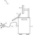
- FIG. 1 is a diagram illustrating an external configuration of an ultrasonic diagnostic apparatus according to an embodiment of the present invention.
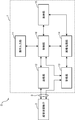
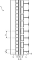
- FIG. 2 is a block diagram showing an electrical configuration of the ultrasonic diagnostic apparatus shown in FIG. 1. It is sectional drawing which shows the structure of the ultrasound probe in the ultrasound diagnosing device shown in FIG. It is a perspective view for demonstrating the manufacturing method in the ultrasonic probe shown in FIG. It is a perspective view for demonstrating the other form of the 2nd piezoelectric part in the ultrasonic probe shown in FIG.
- FIG. 1 is a diagram illustrating an external configuration of an ultrasonic diagnostic apparatus according to an embodiment.
- FIG. 2 is a block diagram illustrating an electrical configuration of the ultrasonic diagnostic apparatus according to the embodiment.
- FIG. 3 is a cross-sectional view illustrating a configuration of an ultrasonic probe in the ultrasonic diagnostic apparatus according to the embodiment.
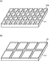
- FIG. 4 is a perspective view for explaining a manufacturing method in the ultrasonic probe of the embodiment. 4A shows the second piezoelectric part during the manufacturing process, and FIG. 4B shows the first piezoelectric part during the manufacturing process.
- FIG. 5 is a perspective view for explaining a modification of the second piezoelectric unit in the ultrasonic probe of the embodiment.
- the ultrasonic diagnostic apparatus S transmits an ultrasonic wave (first ultrasonic signal) to a subject such as a living body (not shown), and is based on the first ultrasonic signal.
- the ultrasonic probe 2 that receives ultrasonic waves (second ultrasonic signal) coming from within the subject, and the ultrasonic probe 2 and the cable 3 are connected to each other, and the cable 3 is connected to the ultrasonic probe 2.
- the ultrasonic probe 2 transmits the first ultrasonic signal to the subject by transmitting a transmission signal of an electrical signal via the, and also comes from within the subject received by the ultrasonic probe 2.
- an ultrasonic diagnostic apparatus main body 1 that images the internal state of the subject as an ultrasonic image based on the received signal of the electrical signal generated by the ultrasonic probe 2 according to the second ultrasonic signal. Configured.
- the ultrasonic waves coming from within the subject based on the first ultrasonic signal are not only reflected waves (echoes) reflected from the first ultrasonic signal in the subject due to acoustic impedance mismatches in the subject, for example,
- an ultrasonic contrast agent such as microbubbles (microbubbles)
- an ultrasonic contrast agent is irradiated with ultrasonic waves, the microbubbles of the ultrasonic contrast agent resonate or resonate, and further collapse or disappear at a sound pressure above a certain threshold.
- ultrasonic waves are generated by resonance of microbubbles or by collapse or disappearance of microbubbles.
- the ultrasonic diagnostic apparatus main body 1 includes an operation input unit 11, a transmission unit 12, a reception unit 13, an image processing unit 14, a display unit 15, and a control unit 16. Configured.
- the operation input unit 11 is a device for inputting data such as a command for instructing the start of diagnosis and personal information of a subject, for example, and is an operation panel or a keyboard provided with a plurality of input switches, for example.
- the transmission unit 12 supplies the transmission signal of the electric signal to the ultrasonic probe 2 via the cable 3 according to the control of the control unit 16, thereby causing the ultrasonic probe 2 to generate the first ultrasonic signal.
- the transmission unit 12 includes, for example, a high voltage pulse generator that generates a high voltage pulse. Then, the transmission unit 12 transmits the first ultrasonic signal of the transmission beam in which the main beam (main beam) is formed in the predetermined direction (predetermined direction) by the plurality of piezoelectric elements constituting the ultrasonic probe 2 into the subject.
- a transmission beamformer for generating a drive signal by adding a delay time to a pulse generated by a high voltage pulse generator by a delay circuit is also provided.
- the drive signal generated by the transmission unit 12 is a plurality of pulse-like signals in which delay times are individually set appropriately for each of the plurality of piezoelectric elements, and the ultrasonic probe 2 is transmitted via the cable 3. Are supplied to each of the plurality of piezoelectric elements. With this plurality of drive signals, the ultrasonic probe 2 causes the phases of the ultrasonic waves radiated from the piezoelectric elements to coincide with each other in a specific direction (specific direction) (or a specific transmission focus point), and the main direction is the main direction. A first ultrasonic signal of the transmission beam forming the beam is generated.
- the predetermined direction is represented by an angle based on a normal direction (0 degree) on a transmission / reception surface of an ultrasonic signal formed by the plurality of piezoelectric elements.
- Such electronic scanning methods include a linear scanning method, a sector scanning method, and a convex method.
- the receiving unit 13 is a circuit that receives a reception signal of an electrical signal from the ultrasonic probe 2 via the cable 3 under the control of the control unit 16, and outputs the reception signal to the image processing unit 14.
- the receiving unit 13 includes, for example, an amplifier that amplifies the received signal with a predetermined amplification factor to compensate for the transmission loss (transmission loss) of the cable 3. Similarly to the formation of the transmission beam at the time of transmission, a reception beam is formed by so-called phasing addition at the time of reception.
- the receiving unit 13 includes, for example, a reception beamformer to which each output signal amplified by the amplifier is input.
- the image processing unit 14 controls the inside of the subject based on a predetermined frequency component in the second ultrasound signal received from the inside of the subject based on the first ultrasound signal received by the receiving unit 13 according to the control of the control unit 16. It is a circuit which forms the image (ultrasonic image) showing the internal state of.
- the predetermined frequency component include a fundamental wave component and harmonic components such as a second harmonic component, a third harmonic component, and a fourth harmonic component.
- the image processing unit 14 may be configured to form an ultrasonic image using a plurality of frequency components.
- the image processing unit 14 performs processing by the DSP (Digital Signal Processor) that generates an ultrasonic image of the subject based on the output of the receiving unit 13 and the DSP to display the ultrasonic image on the display unit 15. And a digital-analog conversion circuit (DAC circuit) for converting the converted signal from a digital signal to an analog signal.
- the DSP includes, for example, a B-mode processing circuit, a Doppler processing circuit, a color mode processing circuit, and the like, and can generate so-called B-mode images, Doppler images, and color mode images.
- the display unit 15 is a device that displays an ultrasonic image of the subject generated by the image processing unit 14 under the control of the control unit 16.
- the display unit 15 is, for example, a display device such as a CRT display, LCD (liquid crystal display), organic EL display, or plasma display, or a printing device such as a printer.
- the control unit 16 includes, for example, a microprocessor, a storage element, and peripheral circuits thereof, and the ultrasonic probe 2, the operation input unit 11, the transmission unit 12, the reception unit 13, the image processing unit 14, and a display. It is a circuit that performs overall control of the ultrasound diagnostic apparatus S by controlling the unit 15 according to the function.
- the ultrasonic probe (ultrasonic probe) 2 is a device that transmits a first ultrasonic signal into the subject and receives a second ultrasonic signal coming from within the subject based on the first ultrasonic signal. It is.
- the ultrasonic probe 2 is laminated on a flat acoustic braking member (acoustic absorption member, backing layer, damper layer) 21 and one main surface of the acoustic braking member 21.
- the first piezoelectric portion 22, the first electrode layer 23 stacked on the first piezoelectric portion 22, the intermediate layer 24 stacked on the first electrode layer 23, and the intermediate layer 24 are stacked on the intermediate layer 24.
- the second electrode layer 25, the second piezoelectric part 26 laminated on the second electrode layer 25, and the acoustic matching layer 27 laminated on the second piezoelectric part 26 are configured.
- the acoustic braking member 21 mechanically supports the first piezoelectric portion 22 and applies an acoustic braking to keep the acoustic characteristics of the first piezoelectric portion 22 good, and is a material that absorbs ultrasonic waves ( Ultrasonic absorbers), and mainly absorbs ultrasonic waves radiated from the first piezoelectric portion 22 toward the acoustic braking member 21.
- Ultrasonic absorbers Ultrasonic absorbers
- the first piezoelectric unit 22 includes a first piezoelectric material, and includes a plurality of first piezoelectric elements that can mutually convert signals between an electrical signal and an ultrasonic signal by using a piezoelectric phenomenon. Configured.
- the first piezoelectric unit 22 is connected to the transmission unit 12 of the ultrasonic diagnostic apparatus body 1 via the cable 3 and is used for transmission for transmitting the first ultrasonic signal into the subject.
- the first piezoelectric unit 22 converts a transmission signal input from the transmission unit 12 of the ultrasonic diagnostic apparatus main body 1 via the cable 3 into an ultrasonic signal and converts the ultrasonic signal to the subject as a first ultrasonic signal. Send.
- the ultrasonic signal generated by the first piezoelectric unit 22 is transmitted into the subject as the first ultrasonic signal, and in this embodiment as described later, A second ultrasonic signal coming from within the subject is received by the second piezoelectric unit 26.
- Each of the plurality of first piezoelectric elements in the first piezoelectric portion 22 includes a pair of first and second electrodes facing each other, and includes a first piezoelectric material between the first and second electrodes.
- the plurality of first piezoelectric elements may be linearly arranged at a predetermined interval from each other to form a one-dimensional linear array type ultrasonic transducer.
- the plurality of first piezoelectric elements Is a two-dimensional array type arranged in two rows linearly independent from each other in a plan view at a predetermined interval, for example, j rows ⁇ k columns in two directions orthogonal to each other.
- An ultrasonic transducer may be configured (j and k are positive integers). Between the first piezoelectric elements in the first piezoelectric portion 22, an ultrasonic absorber that absorbs ultrasonic waves may be filled in order to reduce mutual interference.
- the second piezoelectric portion 26 includes a second piezoelectric material, and includes a plurality of second piezoelectric elements that can mutually convert signals between an electrical signal and an ultrasonic signal by using a piezoelectric phenomenon. Configured.
- the second piezoelectric unit 22 is connected to the receiving unit 13 of the ultrasonic diagnostic apparatus main body 1 via the cable 3, and the second ultrasonic wave coming from within the subject based on the first ultrasonic signal. Used for reception to receive signals.
- the second piezoelectric unit 22 converts the received second ultrasonic signal into an electric signal and outputs the electric signal (reception signal) to the receiving unit 13 of the ultrasonic diagnostic apparatus body 1 via the cable 3.
- Each of the plurality of second piezoelectric elements in the second piezoelectric unit 26 includes a pair of third and fourth electrodes facing each other, like the first piezoelectric element of the first piezoelectric unit 22, and these third and fourth electrodes are provided.
- a second piezoelectric material is provided between the electrodes.
- the plurality of second piezoelectric elements may be linearly arranged at a predetermined interval from each other to form a one-dimensional linear array type ultrasonic transducer.
- the plurality of second piezoelectric elements Is a two-dimensional array type arranged in two rows linearly independent from each other in a plan view with a predetermined interval, for example, arranged in m rows ⁇ n columns in two directions orthogonal to each other.
- An ultrasonic transducer may be configured (m and n are positive integers).
- the first piezoelectric unit 22 and the second piezoelectric unit 26 are configured of the same type, and when the first piezoelectric unit 22 is a one-dimensional linear array type ultrasonic transducer, the second piezoelectric unit 26 is also configured.
- the first piezoelectric unit 22 is a two-dimensional array type ultrasonic transducer
- the second piezoelectric unit 26 is also a two-dimensional array type ultrasonic transducer.
- an ultrasonic absorber that absorbs ultrasonic waves may be filled in order to reduce mutual interference.
- the intermediate layer 24 is a member for laminating the first piezoelectric portion 22 and the second piezoelectric portion 26, and matches the acoustic impedance between the first piezoelectric portion 22 and the second piezoelectric portion 26.
- the first electrode layer 23 is a common ground electrode for grounding each first piezoelectric element of the first piezoelectric unit 22.
- the first piezoelectric element of the first piezoelectric unit 22 has an acoustic braking member in the stacking direction. Electric transmission signals are respectively supplied by signal lines 28 penetrating 21.
- the second electrode layer 25 is a common ground electrode for grounding each second piezoelectric element of the second piezoelectric portion 26, and a signal line (not shown) is connected to each second piezoelectric element of the second piezoelectric portion 26. Connected to each other, an electric reception signal is taken out.
- the first electrode layer 23 is formed on one main surface of the intermediate layer 24, and the second electrode layer 25 is formed on the other main surface of the intermediate layer 24 (main surface opposite to the one main surface).
- the first piezoelectric portion 22 and the second piezoelectric portion 26 are indirectly stacked via the first electrode layer 23, the intermediate layer 24, and the second electrode layer 25.
- the first piezoelectric unit 22 and the second piezoelectric unit 26 may be directly stacked.
- the acoustic matching layer 27 is a member that matches the acoustic impedance of the first piezoelectric unit 22 and the acoustic impedance of the subject, and matches the acoustic impedance of the second piezoelectric unit 26 and the acoustic impedance of the subject.
- the acoustic matching layer 27 may include an acoustic lens that converges an ultrasonic wave that is transmitted toward the subject, and has an arcuate shape.
- the ultrasonic probe 2 of the present embodiment includes the first element pitch P1 in the plurality of first piezoelectric elements of the first piezoelectric unit 22 and the plurality of second elements of the second piezoelectric unit 26.
- the second element pitch P2 in the piezoelectric element is different from each other.
- the element pitches P1 and P2 are distances between the center of the first element and the center of the second element in the first and second elements adjacent to each other, as shown in FIG.
- the first element pitch P1 in the first piezoelectric element of the first piezoelectric portion 22 and the second element pitch P2 in the second piezoelectric element of the second piezoelectric portion 26 are as follows. Since they can be different from each other, the first element pitch P1 is designed to be a pitch (interval) suitable for transmission of the first ultrasonic signal when the first piezoelectric element transmits the first ultrasonic signal. In addition, when the second piezoelectric element receives the second ultrasonic signal, the second element pitch P1 can be designed to a pitch (interval) suitable for reception of the second ultrasonic signal. As a result, side lobes can be reduced and artifacts can be reduced. As a result, an ultrasonic image with higher image quality can be formed.
- the piezoelectric part (the first piezoelectric part 22, the second piezoelectric part 26, and the ultrasonic probe 2) including a plurality of piezoelectric elements
- the element pitch There is the following relation, and from this relational expression 1, it is possible to reduce the side lobes by designing the element pitch appropriately.
- p is the element pitch
- ⁇ the wavelength
- ⁇ is the scanning angle.
- the scanning angle ⁇ may be within a predetermined angle range, but in order to emit the first ultrasonic signal more favorably from the piezoelectric element and to make the second ultrasonic signal incident better to the piezoelectric element, the scanning angle ⁇ Is preferably ⁇ 45 ° ⁇ ⁇ ⁇ + 45 °.
- the second piezoelectric unit 26 should receive a high frequency.
- the ultrasonic probe 2 may be configured to be an approximate value obtained by dividing the first element pitch P1 by the order of the second harmonic.
- the second element pitch P2 of the second piezoelectric unit 26 is substantially equal to the first element pitch P1 of the first piezoelectric unit 22 divided by two.
- the second element pitch P2 is set to a magnitude according to the order of the higher harmonics to be received by the second piezoelectric unit 26, so that the second piezoelectric unit 26 has the order Can be received better (with a higher signal-to-noise ratio).
- Each of the first and second piezoelectric portions 22 and 26 is a one-dimensional linear array type in which the first and second piezoelectric elements are arranged in a row, and a plurality of first piezoelectric elements of the first piezoelectric portion 22 are provided. , Any number from 64 to 512, and the plurality of second piezoelectric elements of the second piezoelectric portion 26 is equal to the number of elements of the plurality of first piezoelectric elements of the first piezoelectric portion 22.
- the ultrasonic probe 2 may be configured to be any one of 2 times to 4 times.
- the ultrasonic probe When forming a tomographic image of the human body using an ultrasonic diagnostic device, the ultrasonic probe must be inserted into the human body or the ultrasonic probe pressed against the body surface.
- the ultrasonic probe is preferably small, and the size of the ultrasonic probe is generally limited to 80 mm because of the size of the flat surface of the body surface in the general physique of the human body. On the other hand, it is desirable that a wider area is made a measurable area by one-time pressing. Considering such circumstances and a general element pitch of about 0.1 to 0.8 mm, the opening size of the ultrasonic probe is preferably about 5 mm to 60 mm, and a margin in a manufacturing process or the like.
- the opening size of the ultrasonic probe is preferably about 6 mm to about 50 mm.
- the number of the first piezoelectric elements of the first piezoelectric portion 22 is from 64 to 512. It is preferable that it is the number in any one of these.
- the number of primes of the piezoelectric element is larger.
- the element pitch is about 0.1 to 0.4 mm. More preferably, it is about 0.1 to 0.2 mm.
- the second element pitch P2 is the second harmonic to the fourth harmonic. Since the size is set according to any one, the second piezoelectric unit 26 can receive the higher-order harmonics of the set order better (with a higher S / N ratio). As a result, when an ultrasonic image is formed by a so-called harmonic imaging technique, it is possible to form an ultrasonic image with higher image quality.
- Each of the first and second piezoelectric portions 22 and 26 is a one-dimensional linear array type in which the first and second piezoelectric elements are arranged in a row, and a plurality of first piezoelectric elements of the first piezoelectric portion 22 are provided. , 64 to 512, and the plurality of second piezoelectric elements of the second piezoelectric portion 26 is equal to the number of elements of the plurality of first piezoelectric elements of the first piezoelectric portion 22.
- the ultrasonic probe 2 may be configured so as to be approximately the order of the higher harmonics to be received by the two piezoelectric units 26.
- the number of second piezoelectric elements in the second piezoelectric unit 26 is approximately equal to the number of first piezoelectric elements in the first piezoelectric unit 22.
- the acoustic probe 2 is configured. By configuring in this way, it is possible to achieve both the handleability of the ultrasound probe 2 and the widening of the diagnostic range, and the second element pitch P2 is higher harmonics to be received by the second piezoelectric unit 26.
- the second piezoelectric unit 26 can receive the higher-order harmonic of the set order better (with a higher S / N ratio). As a result, when an ultrasonic image is formed by a so-called harmonic imaging technique, the ultrasonic image can be formed with higher image quality.
- a transmission signal of an electrical signal is generated by the transmission unit 12 under the control of the control unit 16.
- the generated electrical signal transmission signal is supplied to the ultrasonic probe 2 via the cable 3. More specifically, the transmission signal of the electrical signal is supplied to the first piezoelectric portion 22 in the ultrasonic probe 2, and the first piezoelectric portion 22 has the plurality of first piezoelectric portions in the first piezoelectric portion 22. Each element is supplied with a predetermined delay time. The first piezoelectric element expands and contracts in the thickness direction when the transmission signal of the electric signal is supplied, and ultrasonically vibrates in accordance with the transmission signal of the electric signal.
- the first piezoelectric element Due to this ultrasonic vibration, the first piezoelectric element emits a first ultrasonic signal.
- the first ultrasonic signal radiated from the first piezoelectric element toward the acoustic braking member 21 is absorbed by the acoustic braking member 21.
- the first ultrasonic signal radiated from the first piezoelectric element toward the acoustic matching layer 27 is a first electrode layer 23, an intermediate layer 24, a second electrode layer 25, a second piezoelectric portion 26, and an acoustic matching layer 27. Radiated through. For example, when the ultrasonic probe 2 is in contact with the subject, the first ultrasonic signal is transmitted from the ultrasonic probe 2 to the subject.
- the ultrasound probe 2 may be used in contact with the surface of the subject, or may be used by being inserted into the subject, for example, being inserted into a body cavity of a living body. .
- the ultrasonic wave transmitted to the subject is reflected at one or a plurality of boundary surfaces having different acoustic impedances inside the subject, and becomes a reflected wave of the ultrasonic wave.
- ultrasound is generated by the ultrasound contrast agent due to the first ultrasound signal.
- This ultrasonic wave includes not only the frequency (fundamental fundamental frequency) component of the transmitted first ultrasonic signal but also a harmonic frequency component that is an integral multiple of the fundamental frequency.
- second harmonic components such as twice, three times, and four times the fundamental frequency, third harmonic components, and fourth harmonic components are also included.
- This ultrasonic wave is received by the ultrasonic probe 2.
- the ultrasonic waves are received by the plurality of second piezoelectric elements in the second piezoelectric unit 26 via the acoustic matching layer 27. That is, this ultrasonic wave is received by the second piezoelectric element, and mechanical vibration is converted into an electric signal by the second piezoelectric element and is extracted as a received signal.
- reception signal of this electric signal taken out by the second piezoelectric unit 26 is received by the receiving unit 13 controlled by the control unit 16 via the cable 3.
- the reception unit 13 performs reception processing on the input reception signal, and more specifically, outputs the signal to the image processing unit 14 after amplification, for example.
- the first ultrasonic signal is sequentially transmitted from the first piezoelectric unit 22 toward the subject and reflected by the subject.
- the second ultrasonic signal is received by the second piezoelectric unit 26.
- the image processing unit 14 generates an ultrasound image of the subject based on the reception signal received by the receiving unit 13 from the time from transmission to reception, the received intensity, and the like under the control of the control unit 16.
- the image processing unit 14 extracts a harmonic component from the received signal by a filtering method, and generates an ultrasonic image of the internal state inside the subject using a harmonic imaging technique based on the extracted harmonic component.
- the image processing unit 14 extracts a harmonic component from the received signal by the phase inversion method (pulse inversion method), and uses the harmonic imaging technique based on the extracted harmonic component to inside the subject.
- An ultrasound image of the state is generated.
- the display unit 15 displays the ultrasound image of the subject generated by the image processing unit 14 under the control of the control unit 16.
- the first element pitch P1 of the first piezoelectric portion 22 and the element pitch P2 of the second piezoelectric portion 26 can be different from each other.
- the pitch (interval) suitable for each application can be designed. As a result, side lobes can be reduced and artifacts can be reduced. As a result, an ultrasonic image with higher image quality can be formed.
- the first and second piezoelectric portions 22 and 26 are stacked on each other, so that the size can be reduced.
- first and second piezoelectric portions 22 and 26 are configured to be stacked on each other as described above.
- first and second piezoelectric portions 22 and 26 may be configured to be adjacent to each other on substantially the same plane. Good.
- the first and second piezoelectric materials forming the first and second piezoelectric portions 22 and 26 in the ultrasonic probe 2 may both be inorganic piezoelectric materials, and both may be organic piezoelectric materials. It may be a material, and one may be an inorganic piezoelectric material and the other may be an organic piezoelectric material.
- the inorganic piezoelectric material include so-called PZT, quartz, lithium niobate (LiNbO 3 ), potassium niobate tantalate (K (Ta, Nb) O 3 ), barium titanate (BaTiO 3 ), lithium tantalate (LiTaO 3).
- a polymer of vinylidene fluoride can be used.
- a vinylidene fluoride (VDF) copolymer can be used as the organic piezoelectric material.
- This vinylidene fluoride copolymer is a copolymer (copolymer) of vinylidene fluoride and other monomers. Examples of the other monomers include ethylene trifluoride, tetrafluoroethylene, perfluoroalkyl vinyl ether ( PFA), perfluoroalkoxyethylene (PAE), perfluorohexaethylene, and the like can be used.
- the electromechanical coupling constant (piezoelectric effect) in the thickness direction varies depending on the copolymerization ratio.
- an appropriate copolymerization ratio is adopted according to the specifications of the ultrasonic probe, etc. .
- the copolymerization ratio of vinylidene fluoride is preferably 60 mol% to 99 mol%, and in the case of a composite element in which an organic piezoelectric element is laminated on an inorganic piezoelectric element, The copolymerization ratio of vinylidene is more preferably 85 mol% to 99 mol%.
- polyurea can be used for the organic piezoelectric material.
- PFA perfluoroalkyl vinyl ether
- PAE perfluoroalkoxyethylene
- polyurea it is preferable to produce a piezoelectric body by vapor deposition polymerization.
- a monomer for polyurea there can be mentioned a general formula, H 2 N—R—NH 2 structure.
- R may include an alkylene group, a phenylene group, a divalent heterocyclic group, or a heterocyclic group which may be substituted with any substituent.
- the polyurea may be a copolymer of a urea derivative and another monomer.
- Preferred polyureas include aromatic polyureas using 4,4′-diaminodiphenylmethane (MDA) and 4,4′-diphenylmethane diisocyanate (MDI).
- both the first and second piezoelectric materials are inorganic piezoelectric materials
- a second inorganic piezoelectric body made of a flat inorganic piezoelectric material having a predetermined thickness is prepared, and then Third and fourth electrodes are formed on the two main surfaces over substantially the entire surface by, for example, screen printing, vapor deposition, or sputtering.
- an acoustic matching layer 27 is provided on one main surface via signal lines (not shown).
- a groove (gap, gap, gap, slit) is formed on the second inorganic piezoelectric body with a second element pitch P2 in two directions that are linearly independent in plan view, and the acoustic matching layer 27 is formed on the second inorganic piezoelectric body by, for example, a dicing saw. It is formed in the stacking direction until it is exposed.
- a plurality of inorganic piezoelectric elements are formed as the second piezoelectric elements on the acoustic matching layer 27, and the second piezoelectric part 26A as the second piezoelectric part 26 shown in FIG. 3 is formed. Is done.
- a first inorganic piezoelectric body made of a flat inorganic piezoelectric material having a predetermined thickness is prepared, and then first and second electrodes are respectively formed on both main surfaces almost entirely over, for example, screen printing.
- an acoustic braking member 21 is laminated on one main surface, and then grooves (gap, gap,...) Are linearly independent in two directions in a plan view with a first element pitch P1. Gap, slit) are formed in the first inorganic piezoelectric body in the stacking direction until the acoustic braking member 21 is exposed by, for example, a dicing saw.
- a plurality of signal lines 28 (not shown) for transmitting electrical signals for transmission are formed so as to penetrate the acoustic braking member 21 in the stacking direction.
- each signal line 28 is electrically connected to an electrode layer formed on one main surface of the first inorganic piezoelectric body.
- FIG. 4B a plurality of inorganic piezoelectric elements are formed on the acoustic braking member 21 as the first piezoelectric elements, and the first piezoelectric portion 22 is formed.
- the groove of the first piezoelectric portion 22 and the groove of the second piezoelectric portion 26A are filled with an ultrasonic absorber, and then the first electrode layer 23 is formed on the first piezoelectric portion 22 by, for example, screen printing or vapor deposition.
- the intermediate layer 24 is formed thereon by, for example, screen printing or vapor deposition
- the second electrode layer 25 is formed thereon by, for example, screen printing, vapor deposition, or sputtering.
- the acoustic matching layer 27 and the second piezoelectric portion 26 shown in FIG. 4A are laminated thereon, and the ultrasonic probe 2 having the structure shown in FIG. 3 is manufactured.
- both the first and second piezoelectric materials are organic piezoelectric materials, or when one of the first and second piezoelectric materials is an inorganic piezoelectric material and the other is an organic piezoelectric material, the first and second piezoelectric materials are also used.
- the ultrasonic probe 2 may be manufactured, or when the piezoelectric material is an organic piezoelectric material, a plurality of piezoelectric elements are integrated. A sheet-like piezoelectric portion may be used.
- an organic piezoelectric body 261 made of a flat organic piezoelectric material having a predetermined thickness is prepared, and then a plurality of elementary electrodes 262 separated from each other on one main surface thereof are, for example, a screen. It is formed by printing, vapor deposition or sputtering.
- the plurality of elementary electrodes 262 are formed to be arranged in a two-dimensional array in two linearly independent directions in a plan view, for example, in two directions orthogonal to each other.
- the elementary electrode 262 has, for example, a rectangular shape in plan view.
- an electrode 263 is formed on the other main surface of the organic piezoelectric body 261 over substantially the entire surface by, for example, screen printing, vapor deposition, sputtering, or the like.
- a plurality of elementary electrodes 262 arranged in a two-dimensional array are provided on one main surface, and a piezoelectric portion 26B including an electrode 263 is formed on the other main surface over substantially the entire surface.
- the piezoelectric portion 26B having such a configuration includes a single electrode composed of an element electrode 262, an electrode 263 facing the element electrode 262, and an organic piezoelectric body 261 made of an organic piezoelectric material interposed between the element electrode 262 and the electrode 263.
- An element is configured and includes a plurality of organic piezoelectric elements. Since it is manufactured in this manner, there is no need to form a groove (gap, gap, gap, slit) in the sheet-like organic piezoelectric body 261 in order to form a plurality of organic piezoelectric elements. Accordingly, in such a configuration, a process for forming a groove in the organic piezoelectric element is not necessary, and thus the manufacturing process of the organic piezoelectric element is further simplified, and the ultrasonic probe 2 is manufactured with less man-hours. It becomes possible.
- the second piezoelectric material of the second piezoelectric portion 26 is preferably an organic piezoelectric material. That is, the second piezoelectric portion 26 shown in FIG. 3 is preferably the piezoelectric portion 26B shown in FIG. With this configuration, the second piezoelectric unit 26 (26B) for reception is made of an organic piezoelectric material, so that the second piezoelectric unit 26 (26B) can easily be widened, and the second ultrasonic signal It becomes easier to receive the higher harmonics.
- An ultrasonic probe includes a first piezoelectric material, and a plurality of first probes capable of mutually converting signals between an electric signal and an ultrasonic signal by using a piezoelectric phenomenon.
- a plurality of second piezoelectric elements each including a first piezoelectric part including a piezoelectric element and a second piezoelectric material and capable of mutually converting signals between an electric signal and an ultrasonic signal by utilizing a piezoelectric phenomenon.
- a second piezoelectric unit including an element, wherein the first piezoelectric unit is for transmitting a first ultrasonic signal into a subject, and the second piezoelectric unit is configured to transmit the first ultrasonic signal.
- the second element pitch in the plurality of second piezoelectric elements is mutually It made.
- the first element pitch in the first piezoelectric element of the first piezoelectric portion and the second element pitch in the second piezoelectric element of the second piezoelectric portion can be different from each other.
- the pitch can be designed to a pitch (interval) suitable for transmission of the first ultrasonic signal when the first piezoelectric element transmits the first ultrasonic signal
- the second element pitch is set to the second piezoelectric element.
- the element receives the second ultrasonic signal it can be designed to have a pitch (interval) suitable for receiving the second ultrasonic signal.
- side lobes can be reduced and artifacts can be reduced.
- an ultrasonic image with higher image quality can be formed.
- the element pitch (first element pitch, second element pitch) is a distance between the center of the first element and the center of the second element in the first and second elements adjacent to each other.
- the second element pitch in the plurality of second piezoelectric elements is the second frequency when the frequency of the first ultrasonic signal is a fundamental frequency. This is an approximate value obtained by dividing the first element pitch by the order of higher harmonics to be received by the piezoelectric unit.
- the second element pitch is set to a magnitude corresponding to the order of the higher order harmonics to be received by the second piezoelectric part, so that the second piezoelectric part has the higher order harmonics of the order. Waves can be received better (with a higher signal-to-noise ratio).
- harmonic imaging technique when an ultrasonic image is formed by a so-called harmonic imaging technique, the ultrasonic image can be formed with higher image quality.
- each of the first and second piezoelectric units is a linear array element in which the first and second piezoelectric elements are arranged in a row
- the plurality of first piezoelectric elements of the first piezoelectric portion is any number from 64 to 512
- the plurality of second piezoelectric elements of the second piezoelectric portion is the first piezoelectric portion.
- the number of the plurality of first piezoelectric elements is any one of twice to four times the number of the first piezoelectric elements.
- the second piezoelectric unit can receive the higher-order harmonics of the set order better (with a higher S / N ratio).
- the ultrasonic image can be formed with higher image quality.
- each of the first and second piezoelectric units is a linear array element in which the first and second piezoelectric elements are arranged in a row,
- the plurality of first piezoelectric elements of the first piezoelectric portion is any number from 64 to 512, and the plurality of second piezoelectric elements of the second piezoelectric portion is the first piezoelectric portion.
- the number of the first piezoelectric elements is approximately the order of the higher harmonics to be received by the second piezoelectric unit.
- the second element pitch depends on the order of higher harmonics to be received by the second piezoelectric unit. Therefore, the second piezoelectric unit can receive the higher-order harmonics of the set order better (with a higher S / N ratio). As a result, when an ultrasonic image is formed by a so-called harmonic imaging technique, the ultrasonic image can be formed with higher image quality.
- the second piezoelectric material of the second piezoelectric portion is an organic piezoelectric material.
- the second piezoelectric part for reception is made of an organic piezoelectric material, it is easy to widen the band of the second piezoelectric part, and it is easier to receive high-order harmonics of the second ultrasonic signal. It becomes.
- the first piezoelectric portion and the second piezoelectric portion are stacked in a sound axis direction.
- the size can be reduced.
- the ultrasonic diagnostic apparatus includes any one of the above-described ultrasonic probes.
- an ultrasonic diagnostic apparatus capable of forming an ultrasonic image with higher image quality is provided.
Landscapes
- Engineering & Computer Science (AREA)
- Physics & Mathematics (AREA)
- Health & Medical Sciences (AREA)
- Life Sciences & Earth Sciences (AREA)
- Remote Sensing (AREA)
- Radar, Positioning & Navigation (AREA)
- Acoustics & Sound (AREA)
- Radiology & Medical Imaging (AREA)
- Veterinary Medicine (AREA)
- Heart & Thoracic Surgery (AREA)
- Medical Informatics (AREA)
- Molecular Biology (AREA)
- Surgery (AREA)
- Animal Behavior & Ethology (AREA)
- General Health & Medical Sciences (AREA)
- Public Health (AREA)
- Biomedical Technology (AREA)
- Mechanical Engineering (AREA)
- Pathology (AREA)
- Nuclear Medicine, Radiotherapy & Molecular Imaging (AREA)
- Biophysics (AREA)
- Computer Networks & Wireless Communication (AREA)
- General Physics & Mathematics (AREA)
- Ultra Sonic Daignosis Equipment (AREA)
- Transducers For Ultrasonic Waves (AREA)
Abstract
本発明の超音波探触子2は、第1および第2圧電材料を備えて成り、圧電現象を利用することによって電気信号と超音波信号との間で相互に信号を変換することができる複数の第1および第2圧電素子を備える第1および第2圧電部22、26を備え、第1圧電部22は、被検体内に第1超音波信号を送信するための送信用であり、第2圧電部26は、第1超音波信号に基づく被検体内から来た第2超音波信号を受信するための受信用であり、第1圧電部22の複数の第1圧電素子における第1素子ピッチP1と、第2圧電部26の複数の第2圧電素子における第2素子ピッチP2とは、互いに異なる。
Description
本発明は、超音波を送受信可能な超音波探触子およびこの超音波探触子を備えた超音波診断装置に関する。
超音波は、通常、16000Hz以上の音波をいい、非破壊、無害および略リアルタイムでその内部を調べることが可能なことから、欠陥の検査や疾患の診断等の様々な分野に応用されている。その一つに、被検体内を超音波で走査し、被検体内から来た超音波の反射波(エコー)から生成した受信信号に基づいて当該被検体内の内部状態を画像化する超音波診断装置がある。この超音波診断装置は、医療用では、他の医療用画像装置に較べて小型で安価であり、そしてX線等の放射線被爆が無く安全性が高いこと、また、ドップラ効果を応用した血流表示が可能であること等の様々な特長を有している。このため、超音波診断装置は、循環器系(例えば心臓の冠動脈等の診断)、消化器系(例えば胃腸等の診断)、内科系(例えば肝臓、膵臓および脾臓等の診断)、泌尿器系(例えば腎臓および膀胱等の診断)および産婦人科系等で広く利用されている。この超音波診断装置には、被検体に対して超音波(超音波信号)を送受信する超音波探触子が用いられる。この超音波探触子は、圧電現象を利用することによって、送信の電気信号に基づいて機械振動して超音波(超音波信号)を発生し、被検体内部で音響インピーダンスの不整合によって生じる超音波(超音波信号)の反射波を受けて受信の電気信号を生成する1または複数の圧電素子を備えて構成されている。
また、近年では、超音波診断装置の超音波探触子から被検体内へ送信された超音波の周波数(基本周波数)の周波数成分(基本波成分)ではなく、その基本周波数の整数倍の周波数(高調波周波数)の周波数成分(高調波成分)によって被検体内の内部状態の画像を形成するハーモニックイメージング(Harmonic Imaging)技術が研究、開発されている。このハーモニックイメージング技術は、基本波成分のレベルに比較してサイドローブレベルが小さく、S/N比(signal to noise ratio)が良くなってコントラスト分解能が向上すること、周波数が高くなることによってビーム幅が細くなって横方向分解能が向上すること、近距離では音圧が小さくて音圧の変動が少ないために多重反射が抑制されること、および、焦点以遠の減衰が基本波並みであり高周波を基本波とする場合に較べて深速度を大きく取れること等の様々な利点を有している。このハーモニックイメージング技術には、大別すると、フィルタ法と位相反転法(パルスインバージョン法)との2つの方法がある。このフィルタ法は、高調波検出フィルタにより基本波成分と高調波成分とを分離し、高調波成分だけを抽出し、この高調波成分から、被検体内の内部状態を表す画像(超音波画像)を生成する方法である。また、この位相反転法は、同一方向に続けて互いに位相が反転している第1および第2送信信号を送信し、これら第1および第2送信信号に対応する第1および第2受信信号を加算することによって高調波成分を抽出し、この高調波成分から超音波画像を生成する方法である。第1および第2受信信号における基本波成分は、位相が反転しているが、高調波の例えば2次高調波成分は、同相となるため、第1および第2受信信号を加算することによってこの2次高調波成分が抽出される(例えば特許文献1参照)。
このようなハーモニックイメージング技術に好適に用いられる超音波探触子は、例えば、特許文献2に開示の超音波探触子がある。この特許文献2に開示の超音波探触子は、有機物質で構成された高比誘電率層(強誘電体層)と該高比誘電率層に積層された低比誘電率層とを備える受信用圧電素子と、該受信用圧電素子に積層された送信用圧電素子とを備えて構成される。ところで、この特許文献2に開示の超音波探触子は、ハーモニックイメージング技術に好適に用いることができるが、より高い画質の超音波画像を形成する上で改良の余地がある。
本発明は、上述の事情に鑑みて為された発明であり、その目的は、より高い画質の超音波画像を形成することができる超音波探触子およびこの超音波探触子を用いた超音波診断装置を提供することである。
本発明の超音波探触子およびこの超音波探触子を用いた超音波診断装置は、複数の第1および第2圧電素子を備える第1および第2圧電部を備え、前記第1圧電部における前記複数の第1圧電素子における第1素子ピッチと、前記第2圧電部における前記複数の第2圧電素子における第2素子ピッチP2とは、互いに異なる。この構成によれば、本発明にかかる超音波探触子およびこれを備えた超音波診断装置は、より高い画質の超音波画像を形成することが可能である。
上記並びにその他の本発明の目的、特徴及び利点は、以下の詳細な記載と添付図面から明らかになるであろう。
以下、本発明にかかる実施の一形態を図面に基づいて説明する。なお、各図において同一の符号を付した構成は、同一の構成であることを示し、適宜、その説明を省略する。
図1は、実施形態における超音波診断装置の外観構成を示す図である。図2は、実施形態における超音波診断装置の電気的な構成を示すブロック図である。図3は、実施形態の超音波診断装置における超音波探触子の構成を示す断面図である。図4は、実施形態の超音波探触子における製造方法を説明するための斜視図である。図4(A)は、製造工程中における第2圧電部を示し、図4(B)は、製造工程中における第1圧電部を示す。図5は、実施形態の超音波探触子における第2圧電部の変形形態を説明するための斜視図である。
実施形態における超音波診断装置Sは、図1に示すように、図略の生体等の被検体に対して超音波(第1超音波信号)を送信すると共に、この第1超音波信号に基づく被検体内から来た超音波(第2超音波信号)を受信する超音波探触子2と、超音波探触子2とケーブル3を介して接続され、超音波探触子2へケーブル3を介して電気信号の送信信号を送信することによって超音波探触子2に被検体に対して第1超音波信号を送信させると共に、超音波探触子2で受信された被検体内から来た第2超音波信号に応じて超音波探触子2で生成された電気信号の受信信号に基づいて被検体内の内部状態を超音波画像として画像化する超音波診断装置本体1とを備えて構成される。
この第1超音波信号に基づく被検体内から来た超音波は、被検体内における音響インピーダンスの不整合によって被検体内で第1超音波信号が反射した反射波(エコー)だけでなく、例えば微小気泡(マイクロバブル)等の超音波造影剤(コントラスト剤)が用いられている場合には、第1超音波信号に基づいて超音波造影剤の微小気泡で生成される超音波もある。超音波造影剤では、超音波の照射を受けると、超音波造影剤の微小気泡は、共振もしくは共鳴し、さらに一定の閾値以上の音圧では崩壊、消失する。超音波造影剤では、微小気泡の共振によって、あるいは微小気泡の崩壊、消失によって、超音波が生じている。
超音波診断装置本体1は、例えば、図2に示すように、操作入力部11と、送信部12と、受信部13と、画像処理部14と、表示部15と、制御部16とを備えて構成されている。
操作入力部11は、例えば、診断開始等を指示するコマンドや被検体の個人情報等のデータを入力するための装置であり、例えば、複数の入力スイッチを備えた操作パネルやキーボード等である。
送信部12は、制御部16の制御に従って、超音波探触子2へケーブル3を介して電気信号の送信信号を供給することによって、超音波探触子2に第1超音波信号を発生させる回路である。送信部12は、例えば、高電圧のパルスを生成する高圧パルス発生器等を備えて構成される。そして、送信部12は、超音波探触子2を構成する複数の圧電素子によって所定方向(所定方位)にメインビーム(主ビーム)を形成した送信ビームの第1超音波信号を被検体内へ送信すべく、例えば、高圧パルス発生器で生成されるパスルに遅延回路で遅延時間を付与することによって駆動信号を生成する送信ビームフォーマ等も備える。この送信部12で生成された駆動信号は、複数の圧電素子のそれぞれに対し適宜に遅延時間を個別に設定した、パルス状の複数の信号であり、ケーブル3を介して超音波探触子2における前記複数の圧電素子のそれぞれに供給される。この複数の駆動信号によって超音波探触子2は、各圧電素子から放射された超音波の位相が特定方向(特定方位)(あるいは、特定の送信フォーカス点)において一致し、その特定方向にメインビームを形成した送信ビームの第1超音波信号を発生する。前記所定方向は、前記複数の圧電素子によって形成される超音波信号の送受信面における法線方向を基準(0度)とした角度によって表される。このような電子走査方式には、リニア走査方式、セクタ走査方式およびコンベックス方式等がある。
受信部13は、制御部16の制御に従って、超音波探触子2からケーブル3を介して電気信号の受信信号を受信する回路であり、この受信信号を画像処理部14へ出力する。受信部13は、例えば、ケーブル3の伝送損失(伝送ロス)を補償すべく、受信信号を予め設定された所定の増幅率で増幅する増幅器等を備えて構成される。そして、送信時の送信ビームの形成と同様に、受信時もいわゆる整相加算することによって受信ビームが形成される。すなわち、超音波探触子2における前記複数の圧電素子のそれぞれから出力される複数の出力信号に対し適宜に遅延時間を個別に設定し、これら遅延された複数の出力信号を加算することによって、各出力信号の位相が特定方向(特定方位)(あるいは、特定の受信フォーカス点)において一致し、その特定方向にメインビームが形成される。このような場合において、受信部13は、例えば、前記増幅器で増幅された各出力信号が入力される受信ビームフォーマ等も備える。
画像処理部14は、制御部16の制御に従って、受信部13で受信された、第1超音波信号に基づく被検体内から来た第2超音波信号における所定の周波数成分に基づいて被検体内の内部状態を表す画像(超音波画像)を形成する回路である。前記所定の周波数成分は、例えば、基本波成分、ならびに、例えば2次高調波成分、3次高調波成分および4次高調波成分等の高調波成分を挙げることができる。画像処理部14は、複数の周波数成分を用いて超音波画像を形成するように構成されてもよい。画像処理部14は、例えば、受信部13の出力に基づいて被検体の超音波画像を生成するDSP(Digital Signal Processor)、および、表示部15に超音波画像を表示すべく、前記DSPで処理された信号をディジタル信号からアナログ信号へ変換するディジタル-アナログ変換回路(DAC回路)等を備えて構成される。前記DSPは、例えば、Bモード処理回路、ドプラ処理回路およびカラーモード処理回路等を備え、いわゆるBモード画像、ドプラ画像およびカラーモード画像の生成が可能とされている。
表示部15は、制御部16の制御に従って、画像処理部14で生成された被検体の超音波画像を表示する装置である。表示部15は、例えば、CRTディスプレイ、LCD(液晶ディスプレイ)、有機ELディスプレイおよびプラズマディスプレイ等の表示装置やプリンタ等の印刷装置等である。
制御部16は、例えば、マイクロプロセッサ、記憶素子およびその周辺回路等を備えて構成され、これら超音波探触子2、操作入力部11、送信部12、受信部13、画像処理部14および表示部15を当該機能に応じてそれぞれ制御することによって超音波診断装置Sの全体制御を行う回路である。
また、超音波探触子(超音波プローブ)2は、被検体内に第1超音波信号を送信しこの第1超音波信号に基づく被検体内から来た第2超音波信号を受信する装置である。超音波探触子2は、例えば、図3に示すように、平板状の音響制動部材(音響吸収部材、バッキング層、ダンパ層)21と、この音響制動部材21の一方主面上に積層された第1圧電部22と、この第1圧電部22上に積層された第1電極層23と、この第1電極層23上に積層された中間層24と、この中間層24上に積層された第2電極層25と、この第2電極層25上に積層された第2圧電部26と、この第2圧電部26上に積層された音響整合層27とを備えて構成される。
音響制動部材21は、第1圧電部22を機械的に支持し、また、第1圧電部22の音響特性を良好に保つべく音響的に制動をかけるものであり、超音波を吸収する材料(超音波吸収材)から構成され、主に、第1圧電部22から音響制動部材21方向へ放射される超音波を吸収するものである。
第1圧電部22は、第1圧電材料を備えて成り、圧電現象を利用することによって電気信号と超音波信号との間で相互に信号を変換することができる複数の第1圧電素子を備えて構成される。第1圧電部22は、本実施形態では、ケーブル3を介して超音波診断装置本体1の送信部12に接続され、被検体内に第1超音波信号を送信するための送信用に利用される。第1圧電部22は、超音波診断装置本体1の送信部12からケーブル3を介して入力された送信信号を超音波信号へ変換してこの超音波信号を被検体へ第1超音波信号として送信する。超音波探触子2が被検体に当てられることによって、第1圧電部22で生成された超音波信号が第1超音波信号として被検体内へ送信され、後述するように本実施形態では、被検体内から来た第2超音波信号が第2圧電部26で受信される。
第1圧電部22における複数の第1圧電素子は、それぞれ、互いに対向する一対の第1および第2電極を備え、これら第1および第2電極間に第1圧電材料を備えて構成されている。これら複数の第1圧電素子は、例えば、互いに所定の間隔を空けて直線的に配列され、1次元リニアアレイ型超音波振動子を構成してもよく、また例えば、これら複数の第1圧電素子は、互いに所定の間隔を空けて平面視にて互いに線形独立な2方向に、例えば、互いに直交する2方向にj行×k列で配列され、2次元アレイ状に構成された2次元アレイ型超音波振動子を構成してもよい(j、kは、正の整数である)。第1圧電部22における第1圧電素子間には、相互干渉を低減するために、超音波を吸収する超音波吸収材が充填されてもよい。
第2圧電部26は、第2圧電材料を備えて成り、圧電現象を利用することによって電気信号と超音波信号との間で相互に信号を変換することができる複数の第2圧電素子を備えて構成される。第2圧電部22は、本実施形態では、ケーブル3を介して超音波診断装置本体1の受信部13に接続され、前記第1超音波信号に基づく前記被検体内から来た第2超音波信号を受信するための受信用に利用される。第2圧電部22は、受信した第2超音波信号を電気信号へ変換してこの電気信号(受信信号)をケーブル3を介して超音波診断装置本体1の受信部13へ出力する。
第2圧電部26における複数の第2圧電素子は、それぞれ、第1圧電部22の第1圧電素子と同様に、互いに対向する一対の第3および第4電極を備え、これら第3および第4電極間に第2圧電材料を備えて構成されている。これら複数の第2圧電素子は、例えば、互いに所定の間隔を空けて直線的に配列され、1次元リニアアレイ型超音波振動子を構成してもよく、また例えば、これら複数の第2圧電素子は、互いに所定の間隔を空けて平面視にて互いに線形独立な2方向に、例えば、互いに直交する2方向にm行×n列で配列され、2次元アレイ状に構成された2次元アレイ型超音波振動子を構成してもよい(m、nは、正の整数である)。通常、第1圧電部22と第2圧電部26とは、同一のタイプで構成され、第1圧電部22が1次元リニアアレイ型超音波振動子である場合には、第2圧電部26も1次元リニアアレイ型超音波振動子であり、また、第1圧電部22が2次元アレイ型超音波振動子である場合には、第2圧電部26も2次元アレイ型超音波振動子である。第2圧電部26における第2圧電素子間には、相互干渉を低減するために、超音波を吸収する超音波吸収材が充填されてもよい。
中間層24は、第1圧電部22と第2圧電部26とを積層するための部材であり、第1圧電部22と第2圧電部26との音響インピーダンスを整合させるものである。
第1電極層23は、第1圧電部22の各第1圧電素子をそれぞれ接地するための共通接地電極であり、第1圧電部22の各第1圧電素子には、積層方向に音響制動部材21を貫通する信号線28によって電気の送信信号がそれぞれ供給される。第2電極層25は、第2圧電部26の各第2圧電素子をそれぞれ接地するための共通接地電極であり、第2圧電部26の各第2圧電素子には、図略の信号線が接続されており、電気の受信信信号がそれぞれ取り出される。
第1電極層23は、中間層24の一方主面に形成され、第2電極層25は、中間層24の他方主面(前記一方主面に対向する主面)に形成されている。このように本実施形態では、第1圧電部22と第2圧電部26とは、第1電極層23、中間層24および第2電極層25を介して間接的に積層されている。なお、第1圧電部22と第2圧電部26とは、直接的に積層されてもよい。
音響整合層27は、第1圧電部22の音響インピーダンスと被検体の音響インピーダンスとの整合をとると共に、第2圧電部26の音響インピーダンスと被検体の音響インピーダンスとの整合をとる部材である。そして、音響整合層27は、円弧状に膨出した形状とされる、被検体に向けて送信される超音波を収束する音響レンズを含んでもよい。
ここで、注目すべきは、本実施形態の超音波探触子2は、第1圧電部22の複数の第1圧電素子における第1素子ピッチP1と、第2圧電部26の複数の第2圧電素子における第2素子ピッチP2とは、互いに異なることである。なお、素子ピッチP1、P2とは、図3に示すように、互いに隣接する第1および第2素子における前記第1素子の中心と前記第2素子の中心との間の距離である。
このように本実施形態の超音波探触子2では、第1圧電部22の第1圧電素子における第1素子ピッチP1と第2圧電部26の第2圧電素子における第2素子ピッチP2とは互いに異なるものとすることができるので、第1素子ピッチP1は、第1圧電素子が第1超音波信号を送信する場合にこの第1超音波信号の送信に適したピッチ(間隔)に設計することができるとともに、第2素子ピッチP1は、第2圧電素子が第2超音波信号を受信する場合にこの第2超音波信号の受信に適したピッチ(間隔)に設計することができる。このため、サイドローブを低減することが可能となり、アーチフェクトを低減することができ、この結果、より高い画質の超音波画像を形成することが可能となる。
なお、複数の圧電素子を備える圧電部(第1圧電部22、第2圧電部26、超音波探触子2)の送受信特性において、素子ピッチPと超音波信号の周波数fとの間には、次の関係があり、この関係式1より、素子ピッチを適宜に設計することにより、サイドローブの低減を図ることが可能となる。
p≦λ/(1+|sinθ|) ・・・(1)
ここで、pは、素子ピッチであり、λは、波長であり、θは、走査角である。また、波長λは、音速cと周波数fとの間に、λ=c/fの関係がある。そして、走査角θは、所定の角度範囲でよいが、圧電素子からより良好に第1超音波信号を射出するとともに圧電素子へより良好に第2超音波信号を入射させるために、走査角θは、-45゜≦θ≦+45゜であることが好ましい。
p≦λ/(1+|sinθ|) ・・・(1)
ここで、pは、素子ピッチであり、λは、波長であり、θは、走査角である。また、波長λは、音速cと周波数fとの間に、λ=c/fの関係がある。そして、走査角θは、所定の角度範囲でよいが、圧電素子からより良好に第1超音波信号を射出するとともに圧電素子へより良好に第2超音波信号を入射させるために、走査角θは、-45゜≦θ≦+45゜であることが好ましい。
ここで、第2圧電部26の第2素子ピッチP2が、第1圧電部22から送信される第1超音波信号の周波数を基本周波数とした場合に、第2圧電部26で受信すべき高次高調波の次数で第1素子ピッチP1を割った略値であるように、超音波探触子2が構成されてもよい。例えば、第2圧電部26が2次高調波を主に受信しようとする場合、第2圧電部26の第2素子ピッチP2が第1圧電部22の第1素子ピッチP1を2で割った略値となるように(P2=P1/2)、超音波探触子2が構成される。このように構成することによって、第2素子ピッチP2は、第2圧電部26で受信すべき高次高調波の次数に応じた大きさに設定されるので、第2圧電部26は、前記次数の高次高調波をより良好に(より高いSN比で)受信することが可能となる。この結果、いわゆるハーモニックイメージング技術によって超音波画像を形成する場合に、より高い画質で超音波画像を形成することが可能となる。
また、第1および第2圧電部22、26が、それぞれ、第1および第2圧電素子を1列に配列した1次元リニアアレイ型であり、第1圧電部22の複数の第1圧電素子が、64個から512個までのうちのいずれかの個数であり、第2圧電部26の複数の第2圧電素子が、第1圧電部22の複数の第1圧電素子の素子数に対し、その2倍から4倍までのうちのいずれかであるように、超音波探触子2が構成されてもよい。
超音波診断装置によって人体の断層画像を形成する場合、超音波探触子を人体内部に挿入したり、超音波探触子を体表面に押し当てたり等することになり、挿入の容易性から、超音波探触子は、小さい方が好ましく、また、人体の一般的な体格における体表面の平坦面の大きさから、超音波探触子の大きさは、一般に80mmが限界である。その一方で、一度の押し当てによってより広い領域が測定可能域とされることが望ましい。このような事情、および、一般的な素子ピッチが約0.1ないし0.8mmであることを勘案すると、超音波探触子の開口サイズは、5mmないし60mm程度が好ましく、製造工程等におけるマージンを考慮すると、超音波探触子の開口サイズは、約6mmないし約50mmが好ましく、これを素子数に換算すると、第1圧電部22の複数の第1圧電素子は、64個から512個までのうちのいずれかの個数であることが好ましい。
また、超音波画像をより高解像度化(より精細化)するためには圧電素子の素数がより多い方が好ましく、前記事情およびこの観点から、素子ピッチは、約0.1ないし0.4mmであることがより好ましく、約0.1ないし0.2mmであることがさらにより好ましい。
このように構成することによって、超音波探触子2のハンドリング性と診断範囲の広域化とを両立することができ、第2素子ピッチP2は、第2次高調波ないし第4次高調波のいずれかに応じた大きさに設定されるので、第2圧電部26は、この設定された次数の高次高調波をより良好に(より高いSN比で)受信することが可能となる。この結果、いわゆるハーモニックイメージング技術によって超音波画像を形成する場合に、より高い画質で超音波画像を形成することが可能となる。
また、第1および第2圧電部22、26が、それぞれ、第1および第2圧電素子を1列に配列した1次元リニアアレイ型であり、第1圧電部22の複数の第1圧電素子が、64個から512個までのうちのいずれかの個数であり、第2圧電部26の複数の第2圧電素子が、第1圧電部22の複数の第1圧電素子の素子数に対し、第2圧電部26で受信すべき高次高調波の略次数倍であるように、超音波探触子2が構成されてもよい。例えば、第2圧電部26が2次高調波を主に受信しようとする場合、第2圧電部26における第2圧電素子の素子数が第1圧電部22における第1圧電素子の素子数の略2倍となるように、すなわち、第2圧電部26の第2素子ピッチP2が第1圧電部22の第1素子ピッチP1の略1/2となるように(P2=P1/2)、超音波探触子2が構成される。このように構成することによって、超音波探触子2のハンドリング性と診断範囲の広域化とを両立することができ、第2素子ピッチP2は、第2圧電部26で受信すべき高次高調波の次数に応じた大きさに設定されるので、第2圧電部26は、この設定された次数の高次高調波をより良好に(より高いSN比で)受信することが可能となる。この結果、いわゆるハーモニックイメージング技術によって超音波画像を形成する場合に、より高い画質で前記超音波画像を形成することが可能となる。
このような超音波診断装置Sでは、診断の際に、例えば、操作入力部11から診断開始の指示が入力されると、制御部16の制御によって送信部12で電気信号の送信信号が生成される。この生成された電気信号の送信信号は、ケーブル3を介して超音波探触子2へ供給される。より具体的には、この電気信号の送信信号は、超音波探触子2における第1圧電部22へ供給され、第1圧電部22では、当該第1圧電部22における前記複数の第1圧電素子へ所定の遅延時間でそれぞれ供給される。前記第1圧電素子では、この電気信号の送信信号が供給されることによってその厚さ方向に伸縮し、この電気信号の送信信号に応じて超音波振動する。この超音波振動によって、前記第1圧電素子は、第1超音波信号を放射する。前記第1圧電素子から音響制動部材21方向へ放射された第1超音波信号は、音響制動部材21によって吸収される。また、前記第1圧電素子から音響整合層27方向へ放射された第1超音波信号は、第1電極層23、中間層24、第2電極層25、第2圧電部26および音響整合層27を介して放射される。超音波探触子2が被検体に例えば当接されていると、これによって超音波探触子2から被検体に対して第1超音波信号が送信される。
なお、超音波探触子2は、被検体の表面上に当接して用いられてもよいし、被検体の内部に挿入して、例えば、生体の体腔内に挿入して用いられてもよい。
この被検体に対して送信された超音波は、被検体内部における音響インピーダンスが異なる1または複数の境界面で反射され、超音波の反射波となる。あるいは超音波造影剤が被検体内に注入されている場合には、第1超音波信号に起因して超音波造影剤によって超音波が生成される。この超音波には、送信された第1超音波信号の周波数(基本波の基本周波数)成分だけでなく、基本周波数の整数倍の高調波の周波数成分も含まれる。例えば、基本周波数の2倍、3倍および4倍等の2次高調波成分、3次高調波成分および4次高調波成分等も含まれる。この超音波は、超音波探触子2で受信される。より具体的には、この超音波は、音響整合層27を介して第2圧電部26における複数の第2圧電素子で受信される。すなわち、この超音波は、前記第2圧電素子で受信され、前記第2圧電素子で機械的な振動が電気信号に変換されて受信信号として取り出される。
そして、第2圧電部26で取り出されたこの電気信号の受信信号は、ケーブル3を介して制御部16で制御される受信部13で受信される。受信部13は、この入力された受信信号を受信処理し、より具体的には、例えば増幅した後に画像処理部14へ出力する。
ここで、上述において、方位およびフォーカス深度(観察点)を変えながら電子走査を行うべく、第1圧電部22から順次に第1超音波信号が被検体に向けて送信され、被検体で反射した第2超音波信号が第2圧電部26で受信される。
そして、画像処理部14は、制御部16の制御によって、受信部13で受信された受信信号に基づいて、送信から受信までの時間や受信強度等から被検体の超音波画像を生成する。例えば、画像処理部14では、フィルタ法によって受信信号から高調波成分が抽出され、この抽出された高調波成分に基づいてハーモニックイメージング技術を用いて被検体内部の内部状態の超音波画像が生成される。また例えば、画像処理部14では、位相反転法(パルスインバージョン法)によって受信信号から高調波成分が抽出され、この抽出された高調波成分に基づいてハーモニックイメージング技術を用いて被検体内部の内部状態の超音波画像が生成される。そして、表示部15は、制御部16の制御によって、画像処理部14で生成された被検体の超音波画像を表示する。
このように動作する超音波診断装置Sにおいて、上述したように、第1圧電部22の第1素子ピッチP1と第2圧電部26の素子ピッチP2とは、互いに異なるものとすることができるので、それぞれの用途に適したピッチ(間隔)に設計することができる。このため、サイドローブを低減することが可能となり、アーチフェクトを低減することができ、この結果、より高い画質の超音波画像を形成することが可能となる。
また、上述の超音波診断装置Sにおける超音波探触子2において、第1および第2圧電部22、26が互いに積層されているので、小型化が可能となる。
なお、上述の実施形態では、このように第1および第2圧電部22、26は、互いに積層されて構成されたが、略同一平面で互いに隣接して並設されるように構成されてもよい。
また、上述の実施形態において、超音波探触子2における第1および第2圧電部22、26を形成する第1および第2圧電材料は、共に無機圧電材料であってよく、また共に有機圧電材料であってよく、また一方が無機圧電材料であって他方が有機圧電材料であってもよい。無機圧電材料は、例えば、いわゆるPZT、水晶、ニオブ酸リチウム(LiNbO3)、ニオブ酸タンタル酸カリウム(K(Ta,Nb)O3)、チタン酸バリウム(BaTiO3)、タンタル酸リチウム(LiTaO3)およびチタン酸ストロンチウム(SrTiO3)等である。有機圧電材料は、例えば、フッ化ビニリデンの重合体を用いることができる。また例えば、有機圧電材料は、フッ化ビニリデン(VDF)系コポリマを用いることができる。このフッ化ビニリデン系コポリマは、フッ化ビニリデンと他の単量体との共重合体(コポリマ)であり、他の単量体としては、3フッ化エチレン、テトラフルオロエチレン、パーフルオロアルキルビニルエーテル(PFA)、パーフルオロアルコキシエチレン(PAE)およびパーフルオロヘキサエチレン等を用いることができる。フッ化ビニリデン系コポリマは、その共重合比によって厚み方向の電気機械結合定数(圧電効果)が変化するので、例えば、超音波探触子の仕様等に応じて適宜な共重合比が採用される。例えば、フッ化ビニリデン/3フッ化エチレンのコポリマの場合では、フッ化ビニリデンの共重合比が60mol%~99mol%が好ましく、有機圧電素子を無機圧電素子に積層する複合素子の場合では、フッ化ビニリデンの共重合比が85mol%~99mol%がより好ましい。また、このような複合素子の場合では、他の単量体は、パーフルオロアルキルビニルエーテル(PFA)、パーフルオロアルコキシエチレン(PAE)およびパーフルオロヘキサエチレンが好ましい。また例えば、有機圧電材料は、ポリ尿素を用いることができる。このポリ尿素の場合では、蒸着重合法で圧電体を作成することが好ましい。ポリ尿素用のモノマとして、一般式、H2N-R-NH2構造を挙げることができる。ここで、Rは、任意の置換基で置換されてもよいアルキレン基、フェニレン基、2価のヘテロ環基、ヘテロ環基を含んでもよい。ポリ尿素は、尿素誘導体と他の単量体との共重合体であってもよい。好ましいポリ尿素として、4,4’-ジアミノジフェニルメタン(MDA)と4,4’-ジフェニルメタンジイソシアナート(MDI)を用いる芳香族ポリ尿素を挙げることができる。
例えば、第1および第2圧電材料が共に無機圧電材料である場合には、まず、所定の厚さを持った平板状の無機圧電材料から成る第2無機圧電体が用意され、次に、その両主面に略全面に亘ってそれぞれ第3および第4電極が例えばスクリーン印刷、蒸着あるいはスパッタ等によって形成され、次に、一方主面上に音響整合層27が図略の信号線を介して積層され、次に、平面視にて線形独立な2方向に第2素子ピッチP2で溝(隙間、間隙、ギャップ、スリット)が前記第2無機圧電体に、例えばダイシングソ等によって音響整合層27が露出するまで積層方向に形成される。これによって図4(A)に示すように、音響整合層27上に第2圧電素子として複数の無機圧電素子が形成され、図3に示す第2圧電部26としての第2圧電部26Aが形成される。
また、所定の厚さを持った平板状の無機圧電材料から成る第1無機圧電体が用意され、次に、その両主面に略全面に亘ってそれぞれ第1および第2電極が例えばスクリーン印刷、蒸着あるいはスパッタ等によって形成され、次に、一方主面上に音響制動部材21が積層され、次に、平面視にて線形独立な2方向に第1素子ピッチP1で溝(隙間、間隙、ギャップ、スリット)が前記第1無機圧電体に、例えばダイシングソ等によって音響制動部材21が露出するまで積層方向に形成される。なお、この音響制動部材21内には、積層方向に当該音響制動部材21を貫通するように、送信の電気信号を伝送するための複数の信号線28(不図示)が形成されており、前記第1無機圧電体を音響制動部材21に積層する際には、これら各信号線28は、前記第1無機圧電体の一方主面に形成された電極層に電気的に接続される。これによって図4(B)に示すように、音響制動部材21上に第1圧電素子として複数の無機圧電素子が形成され、第1圧電部22が形成される。
そして、第1圧電部22の前記溝および第2圧電部26Aの前記溝に超音波吸収材が充填され、次に、第1圧電部22上に、第1電極層23が例えばスクリーン印刷、蒸着あるいはスパッタ等によって形成され、次に、その上に中間層24が例えばスクリーン印刷あるいは蒸着等によって形成され、次に、その上に第2電極層25が例えばスクリーン印刷、蒸着あるいはスパッタ等によって形成され、そして、その上に図4(A)に示す前記音響整合層27および第2圧電部26が積層され、図3に示す構造の超音波探触子2が製造される。
また、第1および第2圧電材料が共に有機圧電材料である場合や、第1および第2圧電材料における一方が無機圧電材料であってその他方が有機圧電材料である場合も、第1および第2圧電材料が共に無機圧電材料である場合と同様に、超音波探触子2が製造されてもよいし、あるいは、圧電材料が有機圧電材料である場合に、複数の圧電素子が一体化したシート状の圧電部が用いられてもよい。
より具体的には、まず、所定の厚さを持った平板状の有機圧電材料から成る有機圧電体261が用意され、次に、その一方主面に互いに分離した複数の素電極262が例えばスクリーン印刷、蒸着あるいはスパッタ等によって形成される。これら複数の素電極262は、平面視にて線形独立な2方向に、例えば互いに直交する2方向に2次元アレイ状に配列するように形成される。素電極262は、例えば、平面視にて矩形状とされる。続いて、有機圧電体261の他方主面に略全面に亘って電極263が例えばスクリーン印刷、蒸着あるいはスパッタ等によって形成される。これによって2次元アレイ状に配列された複数の素電極262を一方主面に備えると共に他方主面に略全面に亘って電極263を備える圧電部26Bが形成される。このような構成の圧電部26Bは、素電極262と、これに対向する電極263と、これら素電極262と電極263との間に介在する有機圧電材料の有機圧電体261とから1個の圧電素子が構成され、複数の有機圧電素子を含む。このように製造されるので、複数の有機圧電素子を形成するためにシート状の有機圧電体261に溝(間隙、隙間、ギャップ、スリット)を形成する工程が必要ない。したがって、このような構成では、有機圧電素子に対して溝を形成する工程が必要ではないため、有機圧電素子の製造工程がより単純化され、より少ない工数で超音波探触子2を製造することが可能となる。
ここで、本実施形態では、第2圧電部26の第2圧電材料が有機圧電材料であることが好ましい。すなわち、図3に示す第2圧電部26は、図5に示す圧電部26Bであることが好ましい。このように構成することによって、受信用の第2圧電部26(26B)が有機圧電材料によって構成されるので、第2圧電部26(26B)の広帯域化が容易であり、第2超音波信号の高次高調波の受信がより容易となる。
本明細書は、上記のように様々な態様の技術を開示しているが、そのうち主な技術を以下に纏める。
一態様にかかる超音波探触子は、第1圧電材料を備えて成り、圧電現象を利用することによって電気信号と超音波信号との間で相互に信号を変換することができる複数の第1圧電素子を備える第1圧電部と、第2圧電材料を備えて成り、圧電現象を利用することによって電気信号と超音波信号との間で相互に信号を変換することができる複数の第2圧電素子を備える第2圧電部とを備え、前記第1圧電部は、被検体内に第1超音波信号を送信するための送信用であり、前記第2圧電部は、前記第1超音波信号に基づく前記被検体内から来た第2超音波信号を受信するための受信用であり、前記第1圧電部の前記複数の第1圧電素子における第1素子ピッチと、前記第2圧電部の前記複数の第2圧電素子における第2素子ピッチとは、互いに異なる。
このような構成では、第1圧電部の第1圧電素子における第1素子ピッチと第2圧電部の第2圧電素子における第2素子ピッチとは互いに異なるものとすることができるので、第1素子ピッチは、第1圧電素子が第1超音波信号を送信する場合にこの第1超音波信号の送信に適したピッチ(間隔)に設計することができるとともに、第2素子ピッチは、第2圧電素子が第2超音波信号を受信する場合にこの第2超音波信号の受信に適したピッチ(間隔)に設計することができる。このため、サイドローブを低減することが可能となり、アーチフェクトを低減することができ、この結果、より高い画質の超音波画像を形成することが可能となる。
ここで、前記素子ピッチ(第1素子ピッチ、第2素子ピッチ)は、互いに隣接する第1および第2素子における第1素子の中心と第2素子の中心との間の距離である。
また、他の一態様では、上述の超音波探触子において、前記複数の第2圧電素子における第2素子ピッチは、前記第1超音波信号の周波数を基本周波数とした場合に、前記第2圧電部で受信すべき高次高調波の次数で第1素子ピッチを割った略値である。
この構成によれば、第2素子ピッチは、第2圧電部で受信すべき高次高調波の次数に応じた大きさに設定されるので、前記第2圧電部は、前記次数の高次高調波をより良好に(より高いSN比で)受信することが可能となる。この結果、いわゆるハーモニックイメージング技術によって超音波画像を形成する場合に、より高い画質で前記超音波画像を形成することが可能となる。
また、他の一態様では、上述の超音波探触子において、前記第1および第2圧電部は、それぞれ、前記第1および第2圧電素子を1列に配列したリニアアレイ素子であり、前記第1圧電部の前記複数の第1圧電素子は、64個から512個までのうちのいずれかの個数であり、前記第2圧電部の前記複数の第2圧電素子は、前記第1圧電部の前記複数の第1圧電素子の素子数に対し、その2倍から4倍までのうちのいずれかである。
この構成によれば、超音波探触子のハンドリング性と診断範囲の広域化とを両立することができ、第2素子ピッチは、第2次高調波ないし第4次高調波のいずれかに応じた大きさに設定されるので、前記第2圧電部は、この設定された次数の高次高調波をより良好に(より高いSN比で)受信することが可能となる。この結果、いわゆるハーモニックイメージング技術によって超音波画像を形成する場合に、より高い画質で前記超音波画像を形成することが可能となる。
また、他の一態様では、上述の超音波探触子において、前記第1および第2圧電部は、それぞれ、前記第1および第2圧電素子を1列に配列したリニアアレイ素子であり、前記第1圧電部の前記複数の第1圧電素子は、64個から512個までのうちのいずれかの個数であり、前記第2圧電部の前記複数の第2圧電素子は、前記第1圧電部の前記複数の第1圧電素子の素子数に対し、前記第2圧電部で受信すべき高次高調波の略次数倍である。
この構成によれば、超音波探触子のハンドリング性と診断範囲の広域化とを両立することができ、第2素子ピッチは、第2圧電部で受信すべき高次高調波の次数に応じた大きさに設定されるので、前記第2圧電部は、この設定された次数の高次高調波をより良好に(より高いSN比で)受信することが可能となる。この結果、いわゆるハーモニックイメージング技術によって超音波画像を形成する場合に、より高い画質で前記超音波画像を形成することが可能となる。
また、他の一態様では、これら上述の超音波探触子において、前記第2圧電部の前記第2圧電材料は、有機圧電材料である。
この構成によれば、受信用の第2圧電部が有機圧電材料によって構成されるので、第2圧電部の広帯域化が容易であり、第2超音波信号の高次高調波の受信がより容易となる。
また、他の一態様では、これら上述の超音波探触子において、前記第1圧電部と前記第2圧電部とは、音軸方向で積層されていることを特徴とする。
この構成によれば、第1および第2圧電部が積層されているので、小型化が可能となる。
そして、他の一態様にかかる超音波診断装置は、これら上述のいずれかの超音波探触子を備える。
この構成によれば、より高い画質の超音波画像を形成することができる超音波診断装置が提供される。
この出願は、2009年5月11日に出願された日本国特許出願特願2009-114412を基礎とするものであり、その内容は、本願に含まれるものである。
本発明を表現するために、上述において図面を参照しながら実施形態を通して本発明を適切且つ十分に説明したが、当業者であれば上述の実施形態を変更および/または改良することは容易に為し得ることであると認識すべきである。したがって、当業者が実施する変更形態または改良形態が、請求の範囲に記載された請求項の権利範囲を離脱するレベルのものでない限り、当該変更形態または当該改良形態は、当該請求項の権利範囲に包括されると解釈される。
Claims (7)
- 第1圧電材料を備えて成り、圧電現象を利用することによって電気信号と超音波信号との間で相互に信号を変換することができる複数の第1圧電素子を備える第1圧電部と、
第2圧電材料を備えて成り、圧電現象を利用することによって電気信号と超音波信号との間で相互に信号を変換することができる複数の第2圧電素子を備える第2圧電部とを備え、
前記第1圧電部は、被検体内に第1超音波信号を送信するための送信用であり、
前記第2圧電部は、前記第1超音波信号に基づく前記被検体内から来た第2超音波信号を受信するための受信用であり、
前記第1圧電部の前記複数の第1圧電素子における第1素子ピッチと、前記第2圧電部の前記複数の第2圧電素子における第2素子ピッチとは、互いに異なること
を特徴とする超音波探触子。 - 前記複数の第2圧電素子における第2素子ピッチは、前記第1超音波信号の周波数を基本周波数とした場合に、前記第2圧電部で受信すべき高次高調波の次数で第1素子ピッチを割った略値であること
を特徴とする請求項1に記載の超音波探触子。 - 前記第1および第2圧電部は、それぞれ、前記第1および第2圧電素子を1列に配列したリニアアレイ素子であり、
前記第1圧電部の前記複数の第1圧電素子は、64個から512個までのうちのいずれかの個数であり、
前記第2圧電部の前記複数の第2圧電素子は、前記第1圧電部の前記複数の第1圧電素子の素子数に対し、その2倍から4倍までのうちのいずれかであること
を特徴とする請求項1に記載の超音波探触子。 - 前記第1および第2圧電部は、それぞれ、前記第1および第2圧電素子を1列に配列したリニアアレイ素子であり、
前記第1圧電部の前記複数の第1圧電素子は、64個から512個までのうちのいずれかの個数であり、
前記第2圧電部の前記複数の第2圧電素子は、前記第1圧電部の前記複数の第1圧電素子の素子数に対し、前記第2圧電部で受信すべき高次高調波の略次数倍であること
を特徴とする請求項1に記載の超音波探触子。 - 前記第2圧電部の前記第2圧電材料は、有機圧電材料であること
を特徴とする請求項1ないし請求項4のいずれか1項に記載の超音波探触子。 - 前記第1圧電部と前記第2圧電部とは、音軸方向で積層されていること
を特徴とする請求項1ないし請求項5のいずれか1項に記載の超音波探触子。 - 被検体に対して第1超音波信号を送信すると共に、前記第1超音波信号に基づく前記被検体内から来た第2超音波信号を受信する超音波探触子と、
前記超音波探触子に前記被検体に対して前記第1超音波信号を送信させると共に、前記超音波探触子で受信された前記被検体内から来た前記第2超音波信号に基づいて前記被検体内の内部状態を超音波画像として画像化する超音波診断装置本体とを備え、
前記超音波探触子は、請求項1ないし請求項6のいずれか1項に記載の超音波探触子であること
を特徴とする超音波診断装置。
Priority Applications (1)
| Application Number | Priority Date | Filing Date | Title |
|---|---|---|---|
| JP2011513215A JP5582139B2 (ja) | 2009-05-11 | 2010-02-19 | 超音波探触子および超音波診断装置 |
Applications Claiming Priority (2)
| Application Number | Priority Date | Filing Date | Title |
|---|---|---|---|
| JP2009-114412 | 2009-05-11 | ||
| JP2009114412 | 2009-05-11 |
Publications (1)
| Publication Number | Publication Date |
|---|---|
| WO2010131394A1 true WO2010131394A1 (ja) | 2010-11-18 |
Family
ID=43084780
Family Applications (1)
| Application Number | Title | Priority Date | Filing Date |
|---|---|---|---|
| PCT/JP2010/001088 Ceased WO2010131394A1 (ja) | 2009-05-11 | 2010-02-19 | 超音波探触子および超音波診断装置 |
Country Status (2)
| Country | Link |
|---|---|
| JP (1) | JP5582139B2 (ja) |
| WO (1) | WO2010131394A1 (ja) |
Cited By (7)
| Publication number | Priority date | Publication date | Assignee | Title |
|---|---|---|---|---|
| CN103006258A (zh) * | 2011-09-27 | 2013-04-03 | 富士胶片株式会社 | 超声诊断设备和超声图像生成方法 |
| JP2013074375A (ja) * | 2011-09-27 | 2013-04-22 | Fujifilm Corp | 超音波探触子およびその製造方法 |
| US9056333B2 (en) | 2011-09-27 | 2015-06-16 | Fujifilm Corporation | Ultrasound probe and method of producing the same |
| JP2018164048A (ja) * | 2017-03-27 | 2018-10-18 | 日東電工株式会社 | 圧電積層体 |
| JP2020520140A (ja) * | 2017-04-28 | 2020-07-02 | ザ ボード オブ トラスティーズ オブ ザ レランド スタンフォード ジュニア ユニバーシティー | 音響生体識別タッチスキャナ |
| JP2021034968A (ja) * | 2019-08-28 | 2021-03-01 | 株式会社東芝 | 超音波センサ |
| JP2021034969A (ja) * | 2019-08-28 | 2021-03-01 | 株式会社東芝 | 超音波センサ |
Families Citing this family (1)
| Publication number | Priority date | Publication date | Assignee | Title |
|---|---|---|---|---|
| KR101818311B1 (ko) * | 2015-12-07 | 2018-01-12 | 동국대학교 산학협력단 | 고조파 영상 구현을 위한 배열형 초음파 변환자 및 그 제조 방법 |
Citations (4)
| Publication number | Priority date | Publication date | Assignee | Title |
|---|---|---|---|---|
| JPH11276478A (ja) * | 1998-03-26 | 1999-10-12 | Fujitsu Ltd | 超音波探触子および超音波診断装置 |
| JP2003169800A (ja) * | 2000-02-01 | 2003-06-17 | Hitachi Medical Corp | 超音波探触子およびこれを用いた超音波診断装置 |
| JP2003305043A (ja) * | 2002-03-26 | 2003-10-28 | Ge Medical Systems Global Technology Co Llc | 高調波変換器素子構造及び特性 |
| JP2006320415A (ja) * | 2005-05-17 | 2006-11-30 | Toshiba Corp | 超音波プローブ及び超音波診断装置 |
Family Cites Families (2)
| Publication number | Priority date | Publication date | Assignee | Title |
|---|---|---|---|---|
| JP4632728B2 (ja) * | 2004-09-10 | 2011-02-16 | 株式会社東芝 | 超音波プローブおよび超音波画像診断装置 |
| JP4945769B2 (ja) * | 2005-07-26 | 2012-06-06 | サーフ テクノロジー アクティーゼルスカブ | 二重周波数帯域の超音波送受波器アレイ |
-
2010
- 2010-02-19 WO PCT/JP2010/001088 patent/WO2010131394A1/ja not_active Ceased
- 2010-02-19 JP JP2011513215A patent/JP5582139B2/ja not_active Expired - Fee Related
Patent Citations (4)
| Publication number | Priority date | Publication date | Assignee | Title |
|---|---|---|---|---|
| JPH11276478A (ja) * | 1998-03-26 | 1999-10-12 | Fujitsu Ltd | 超音波探触子および超音波診断装置 |
| JP2003169800A (ja) * | 2000-02-01 | 2003-06-17 | Hitachi Medical Corp | 超音波探触子およびこれを用いた超音波診断装置 |
| JP2003305043A (ja) * | 2002-03-26 | 2003-10-28 | Ge Medical Systems Global Technology Co Llc | 高調波変換器素子構造及び特性 |
| JP2006320415A (ja) * | 2005-05-17 | 2006-11-30 | Toshiba Corp | 超音波プローブ及び超音波診断装置 |
Cited By (11)
| Publication number | Priority date | Publication date | Assignee | Title |
|---|---|---|---|---|
| CN103006258A (zh) * | 2011-09-27 | 2013-04-03 | 富士胶片株式会社 | 超声诊断设备和超声图像生成方法 |
| JP2013070734A (ja) * | 2011-09-27 | 2013-04-22 | Fujifilm Corp | 超音波診断装置および超音波画像生成方法 |
| JP2013074375A (ja) * | 2011-09-27 | 2013-04-22 | Fujifilm Corp | 超音波探触子およびその製造方法 |
| US8876718B2 (en) | 2011-09-27 | 2014-11-04 | Fujifilm Corporation | Ultrasound diagnostic apparatus and ultrasound image generating method |
| US9056333B2 (en) | 2011-09-27 | 2015-06-16 | Fujifilm Corporation | Ultrasound probe and method of producing the same |
| JP2018164048A (ja) * | 2017-03-27 | 2018-10-18 | 日東電工株式会社 | 圧電積層体 |
| JP2020520140A (ja) * | 2017-04-28 | 2020-07-02 | ザ ボード オブ トラスティーズ オブ ザ レランド スタンフォード ジュニア ユニバーシティー | 音響生体識別タッチスキャナ |
| JP2021034968A (ja) * | 2019-08-28 | 2021-03-01 | 株式会社東芝 | 超音波センサ |
| JP2021034969A (ja) * | 2019-08-28 | 2021-03-01 | 株式会社東芝 | 超音波センサ |
| JP7133521B2 (ja) | 2019-08-28 | 2022-09-08 | 株式会社東芝 | 超音波センサ |
| JP7222850B2 (ja) | 2019-08-28 | 2023-02-15 | 株式会社東芝 | 超音波センサ |
Also Published As
| Publication number | Publication date |
|---|---|
| JPWO2010131394A1 (ja) | 2012-11-01 |
| JP5582139B2 (ja) | 2014-09-03 |
Similar Documents
| Publication | Publication Date | Title |
|---|---|---|
| JP5582139B2 (ja) | 超音波探触子および超音波診断装置 | |
| JP2009296055A (ja) | 超音波探触子およびそれを用いる超音波診断装置 | |
| US20120220872A1 (en) | Ultrasound probe and ultrasound diagnostic apparatus | |
| JP5504921B2 (ja) | 超音波探触子および超音波診断装置 | |
| JP2011010794A (ja) | 超音波探触子およびそれを備えた超音波診断装置 | |
| JP2013146478A (ja) | 超音波探触子および超音波診断装置 | |
| Vos et al. | Transducer for harmonic intravascular ultrasound imaging | |
| JP4910999B2 (ja) | 超音波探触子および超音波診断装置 | |
| JP2009297326A (ja) | 超音波探触子および超音波診断装置 | |
| JP5552820B2 (ja) | 超音波探触子および超音波診断装置 | |
| JP4911000B2 (ja) | 超音波探触子および超音波診断装置 | |
| JP2011109448A (ja) | 超音波探触子およびそれを用いる超音波診断装置 | |
| JP2013070734A (ja) | 超音波診断装置および超音波画像生成方法 | |
| JP5682762B2 (ja) | 圧電デバイスおよび超音波探触子 | |
| JP5169845B2 (ja) | 超音波診断装置 | |
| US20150313576A1 (en) | Ultrasound diagnostic apparatus | |
| JP5472289B2 (ja) | 超音波診断装置 | |
| JP2009268807A (ja) | 超音波診断装置 | |
| Vos et al. | A 20-40 MHz ultrasound transducer for intravascular harmonic imaging | |
| JP5146101B2 (ja) | 超音波診断装置 | |
| JP2010213903A (ja) | 超音波診断装置 | |
| JP5299128B2 (ja) | 超音波探触子、超音波診断装置 | |
| JP5481971B2 (ja) | 超音波診断装置 | |
| JP2010051546A (ja) | 超音波振動子およびそれを用いる超音波診断装置 | |
| JP2010213906A (ja) | 超音波診断装置 |
Legal Events
| Date | Code | Title | Description |
|---|---|---|---|
| 121 | Ep: the epo has been informed by wipo that ep was designated in this application |
Ref document number: 10774656 Country of ref document: EP Kind code of ref document: A1 |
|
| WWE | Wipo information: entry into national phase |
Ref document number: 2011513215 Country of ref document: JP |
|
| NENP | Non-entry into the national phase |
Ref country code: DE |
|
| 122 | Ep: pct application non-entry in european phase |
Ref document number: 10774656 Country of ref document: EP Kind code of ref document: A1 |