WO2010125912A1 - 部品組付け装置及び方法 - Google Patents
部品組付け装置及び方法 Download PDFInfo
- Publication number
- WO2010125912A1 WO2010125912A1 PCT/JP2010/056640 JP2010056640W WO2010125912A1 WO 2010125912 A1 WO2010125912 A1 WO 2010125912A1 JP 2010056640 W JP2010056640 W JP 2010056640W WO 2010125912 A1 WO2010125912 A1 WO 2010125912A1
- Authority
- WO
- WIPO (PCT)
- Prior art keywords
- component
- assembly
- unit
- assembling
- component supply
- Prior art date
- Legal status (The legal status is an assumption and is not a legal conclusion. Google has not performed a legal analysis and makes no representation as to the accuracy of the status listed.)
- Ceased
Links
Images


Classifications
-
- B—PERFORMING OPERATIONS; TRANSPORTING
- B23—MACHINE TOOLS; METAL-WORKING NOT OTHERWISE PROVIDED FOR
- B23P—METAL-WORKING NOT OTHERWISE PROVIDED FOR; COMBINED OPERATIONS; UNIVERSAL MACHINE TOOLS
- B23P19/00—Machines for simply fitting together or separating metal parts or objects, or metal and non-metal parts, whether or not involving some deformation; Tools or devices therefor so far as not provided for in other classes
- B23P19/04—Machines for simply fitting together or separating metal parts or objects, or metal and non-metal parts, whether or not involving some deformation; Tools or devices therefor so far as not provided for in other classes for assembling or disassembling parts
- B23P19/06—Screw or nut setting or loosening machines
-
- B—PERFORMING OPERATIONS; TRANSPORTING
- B23—MACHINE TOOLS; METAL-WORKING NOT OTHERWISE PROVIDED FOR
- B23P—METAL-WORKING NOT OTHERWISE PROVIDED FOR; COMBINED OPERATIONS; UNIVERSAL MACHINE TOOLS
- B23P19/00—Machines for simply fitting together or separating metal parts or objects, or metal and non-metal parts, whether or not involving some deformation; Tools or devices therefor so far as not provided for in other classes
- B23P19/001—Article feeders for assembling machines
-
- B—PERFORMING OPERATIONS; TRANSPORTING
- B23—MACHINE TOOLS; METAL-WORKING NOT OTHERWISE PROVIDED FOR
- B23P—METAL-WORKING NOT OTHERWISE PROVIDED FOR; COMBINED OPERATIONS; UNIVERSAL MACHINE TOOLS
- B23P21/00—Machines for assembling a multiplicity of different parts to compose units, with or without preceding or subsequent working of such parts, e.g. with programme control
- B23P21/004—Machines for assembling a multiplicity of different parts to compose units, with or without preceding or subsequent working of such parts, e.g. with programme control the units passing two or more work-stations whilst being composed
- B23P21/006—Machines for assembling a multiplicity of different parts to compose units, with or without preceding or subsequent working of such parts, e.g. with programme control the units passing two or more work-stations whilst being composed the conveying means comprising a rotating table
Definitions
- the present invention relates to a part assembling apparatus and method for assembling parts such as electronic parts or mechanical parts, and more particularly, to a part assembling apparatus and method for assembling parts on an assembling object that is intermittently conveyed in a positioned state.
- a work supply unit including an index table that holds a work (assembly object) for fastening screws and intermittently conveys the work, and is arranged at a position separated from the index table in the horizontal direction.
- a screw supply unit that supplies screws, a driver unit (assembly tool) that holds and holds screws supplied by the screw supply unit, and an index table from the screw supply position of the screw supply unit
- a device including a driver unit driving means for driving the driver unit to move up and down and move in the horizontal direction so as to convey the screw to the upper assembly position (screw fastening position) is known (for example, Patent Documents). 1).
- an index table that is disposed substantially at the center and holds a work (assembly target object) and rotates intermittently, and an index table that is disposed in the outer peripheral area of the index table and is freely movable up and down.
- a workpiece supply unit including a chuck that freely rotates and grips a workpiece, a detection unit that is disposed in an outer peripheral region of the index table and detects a position of a rivet hole of the workpiece, and an outer peripheral region of the index table (separate in the horizontal direction)
- a rivet supply index portion (supply unit) that is arranged to supply rivets, a rivet insertion portion that holds a rivet and inserts it into a rivet hole of a workpiece, and a press portion that clamps and crimps the rivet inserted into the workpiece , Inspection unit for inspecting the rivet caulking state, unloading unit for unloading workpieces from the index table, etc.
- Those with is known (e.g., see Patent Document 2).
- components necessary for assembly are supplied at a supply position of a supply unit arranged in the outer peripheral area of the index table, and a driver for assembling the components Parts are supplied by the unit or rivet insertion portion moving horizontally between the supply position on the supply unit and the assembly position on the index table, so that the driver unit or rivet insertion portion is moved in the horizontal direction.
- Drive mechanism is required, and the assembly unit time is lost due to the horizontal movement of the driver unit or the rivet insertion portion.
- a drive mechanism for moving in the horizontal direction is required, there is a possibility that a mechanical positioning error occurs.
- the installation area of the apparatus around the index table is increased.
- the present invention has been made in view of the above-mentioned conventional technology, and the object of the present invention is to simplify the structure, consolidate the structure, reduce the cost, increase the operating rate, etc.
- the space required for factories and other facilities can be used effectively by reducing the installation area of the machine (and saving space), and it can be flexibly adapted to different models, and there are few mechanical errors and high precision of minute parts. It is an object of the present invention to provide a component assembling apparatus and method that can be assembled to a machine.
- the component assembling apparatus of the present invention is arranged below the assembly target positioned at the work position, the transport unit for holding and transporting the assembly target, and positioned at a predetermined work position.
- a component supply unit that demarcates a component supply position corresponding to the assembly position of the object and supplies and positions the component, and a standby unit that is disposed above the assembly target positioned at the work position and corresponds to the assembly position.
- An assembly unit having an assembly tool that is supported so as to be movable up and down between the position and the component supply position and can be assembled to an assembly object by receiving the component positioned at the component supply position, and the assembly tool is in the component supply position It includes a lift drive unit that receives the components positioned in the position and drives the assembly unit to move up and down to be mounted on the assembly object positioned at the work position. .
- the assembly unit having the assembly tool between the standby position above the work position (conveyance unit) and the component supply position below the work position (conveyance unit) is Driven up and down, the assembly tool receives the components supplied to the component supply position (defined by the component supply unit) below the work position (conveyance unit) and rises to the top of the conveyance unit (standby position), After that, when the transport unit holds the object to be assembled and positions it at a predetermined work position where it is transported and parts are assembled, the assembly tool is lowered again and the parts are assembled to the object to be assembled.
- the assembly unit having the assembly tool is arranged above the work position (conveyance unit), and the assembly tool can be moved up and down from the work position (conveyance unit). Since the component supply unit that demarcates the supply position is arranged, the space in the vertical direction can be used effectively, and the installation area of the device can be reduced (saving) while achieving simplification of the structure and integration of the structure. Space). In addition, the assembly unit only moves up and down and does not move in the horizontal direction, so the structure of the lifting drive unit can be simplified, and errors due to movement in the horizontal direction do not occur. (For example, screws) can be assembled with high accuracy. Furthermore, since the assembly unit (assembly tool) only moves up and down to receive and assemble parts, useless movement can be eliminated and handling time required from receipt of parts to assembly is reduced. Can do.
- the assembly tool and the component supply position are arranged on a vertical axis extending in the vertical direction through the assembly position of the assembly object positioned at the work position, and the elevating drive unit includes the assembly tool.
- a configuration including a guide member that guides the assembly unit so as to move up and down along the vertical axis can be adopted. According to this configuration, when the assembling unit is raised and lowered by the elevating drive unit, the assembling unit is guided by the guide member, and the assembling tool is moved down on the vertical axis and positioned at the component supply position. Therefore, the parts can be received with high accuracy.
- the component supply unit includes a plurality of parts on the second circular orbit that is coaxial with the center of the common first circular orbit passing through a plurality of assembling positions of the assembly object positioned at the work position and on the same diameter. And a rotating member that rotates about the same axis, the rotating member having a circular outer contour and a plurality of component supplying positions at the periphery thereof, upward and radially outward.
- the component supply unit includes a circular rotating member, a component introducing member that defines a component introducing path for guiding components from the radial outer side of the circular rotating member toward the component accommodating portion, and introduction of the component into the component accommodating portion.
- a configuration including a cylindrical fixing member that allows the rotation of the circular rotating member and a cylindrical fixing member that allows the rotation of the circular rotating member According to this configuration, the components that are continuously supplied through the component introduction passage of the component introduction member are sequentially transferred to the plurality of component accommodating portions by appropriately rotating the circular rotating member with respect to the cylindrical fixing member.
- the circular rotary member is accommodated and held, and is positioned at the component supply position by stopping at the predetermined rotational position.
- the component supply unit has a structure including a circular rotating member having a component accommodating portion, a component introducing member, a cylindrical fixing member, and a driving mechanism for the circular rotating member, the structure is provided while supplying a plurality of components. Simplification, integration, miniaturization, etc. can be achieved.
- the cylindrical fixing member may have a configuration having an opening that allows the component introduction passage to communicate with the component accommodating portion when the circular rotating member is at a predetermined rotation angle position.
- the simple structure in which the opening is formed in the cylindrical fixing member allows the introduction of the component into the component accommodating portion in cooperation with the rotation of the circular rotating member, and the introduction of the component into the component accommodating portion. Can be cut off.
- the component supply unit defines a component supply position and is supported and movable linearly in a predetermined direction parallel to the arrangement direction of the plurality of assembly positions of the assembly target objects positioned at the work position.
- the movable member includes a component receiving portion formed so as to open upward and horizontally in the horizontal direction perpendicular to the predetermined direction so as to define a component supply position, and to slide in a predetermined direction.
- a configuration consisting of possible slide members can be employed. According to this configuration, the movable member (sliding member) is appropriately moved in a predetermined direction while achieving simplification and downsizing of the component supply unit, so that the component supply position corresponding to the plurality of assembly positions can be obtained from below. Parts can be supplied and positioned.
- the component supply unit defines a slide member and a component introduction passage for guiding the component toward the component accommodating portion, permits introduction of the component into the component accommodating portion, and is used for the component accommodated in the component accommodating portion. It is possible to adopt a configuration including a component introduction member that defines a wall surface that regulates dropping and a drive mechanism that slide-drives the slide member. According to this configuration, the components that are continuously supplied through the component introduction passage of the component introduction member are accommodated in the component accommodation portion by appropriately moving the slide member relative to the wall surface of the component introduction member. The slide member is held at a predetermined position and positioned at the component supply position.
- the component supply unit has a structure including a slide member having a component accommodating portion, a component introduction member, and a drive mechanism for the slide member, the structure is simplified and integrated while continuously supplying components. Thus, miniaturization and the like can be achieved.
- the said structure WHEREIN The structure which has a some assembly
- a screw tightening tool such as a driver, a press-fit tool, etc.
- the above configuration further includes a fixed base provided with the transport unit and a movable base that can move two-dimensionally in a horizontal plane with respect to the fixed base, and the movable base holds the assembly unit and the component supply unit. And a first movable frame supported so as to be movable in a first direction within a horizontal plane, and a second movable frame supported so as to be movable in a second direction perpendicular to the first direction within the horizontal plane while holding the first movable frame.
- a configuration including a frame and a support frame provided on the fixed base and movably supporting the second movable frame can be employed.
- the transport unit is arranged on the fixed base, and the assembly unit and the component supply unit are on the movable base (the first movable frame) that can move two-dimensionally in a horizontal plane with respect to the fixed base. Since they are arranged, the relative positional relationship between the assembly unit and the component supply unit (component supply position) is maintained. Therefore, when the object to be assembled is changed, the movable base is appropriately moved and positioned at a predetermined position, so that various assembly objects having different assembling positions are not displaced. Parts can be assembled with high accuracy.
- the transport unit has a plurality of holding portions formed to protrude radially at predetermined intervals in the circumferential direction so as to hold the assembly target portion, and a rotary table that rotates around a predetermined vertical axis;
- a configuration including a drive mechanism that intermittently rotationally drives the rotary table can be employed.
- the apparatus can be downsized compared to a case where a conveyor or the like that is long in a predetermined direction is used as the transport unit.
- the assembly tool is defined between the holding portions. It can be raised and lowered smoothly so as not to interfere with the rotary table at the position facing the opening.
- the transport unit may employ a configuration including a holding unit that holds the assembly target, and a drive mechanism that moves and positions the holding unit along the transport track extending in a predetermined direction.
- a plurality of component assembling stations an assembling unit having an assembling tool, a component supplying unit, and a lifting drive unit
- the control unit includes a control unit that controls the transport unit, the component supply unit, the assembly tool, and the elevation drive unit, and the control unit controls the component supply unit to supply and position the component at the component supply position.
- the elevating drive unit and the assembly unit are controlled to be raised again to the standby position, the conveyance unit is controlled to convey the assembly object and position it at the work position, It is possible to adopt a configuration in which the elevating drive unit and the assembling tool are controlled so that the assembling tool is brought close to the assembling object positioned at the work position and the parts are assembled. According to this configuration, it is possible to eliminate a useless operation, to reduce mechanical errors, to assemble minute parts to an object to be assembled with high accuracy, and to achieve a high operating rate.
- the component assembling method of the present invention is a component assembling method for assembling a component with respect to an assembling object positioned at a predetermined work position, and below the assembling object positioned at the working position.
- the component is supplied to the component supply position corresponding to the assembly position and is disposed above the assembly target positioned at the work position.
- the assembly tool is lowered and the part positioned at the part supply position is received, it is raised again to the standby position, and the assembly unit is transported to the work position while being transported by the transport unit, and is positioned at the work position.
- the assembly tool is lowered toward the assembly position of the assembly object, and the parts are assembled to the assembly object. According to this configuration, it is possible to eliminate a useless operation, to reduce mechanical errors, to assemble minute parts to an object to be assembled with high accuracy, and to achieve a high operating rate.
- the factory is reduced in the installation area (space saving) while simplifying the structure, consolidating the structure, reducing the cost, increasing the operating rate, etc. It is possible to effectively use a space such as the above, and to flexibly deal with different models, and it is possible to assemble minute parts with high accuracy with little mechanical error.
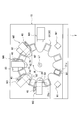
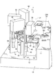
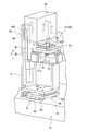
- FIG. 2 is a plan view illustrating a state in which a transport unit (rotary table) is rotated by a predetermined angle in the component assembly apparatus illustrated in FIG. 1. It is a fragmentary perspective view of the component assembly apparatus shown in FIG. It is a fragmentary perspective view of the component assembly apparatus shown in FIG. It is a perspective view which shows the components supply unit contained in the components assembly apparatus shown in FIG. It is a perspective view which shows the components supply unit contained in the components assembly apparatus shown in FIG. FIG.
- FIG. 2 is a partial perspective view showing a positional relationship between an assembly unit (assembly tool) and a component supply unit (components supplied to a component supply position) included in the component assembly apparatus shown in FIG. 1.
- FIG. 2 is a partial perspective view showing a positional relationship between an assembly unit (assembly tool) and a component supply unit (components supplied to a component supply position) included in the component assembly apparatus shown in FIG. 1.
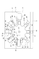
- this component assembling apparatus is provided along a base 10, a transport unit 20 provided on the base 10, and a transport direction (circumferential direction) R of the transport unit 20 (rotary table 21 thereof).
- the base 10 is used to perform a work of transferring a plurality of work units M1, M2, M3, M4, M5, M6, M7, an assembly target W1 to the transport unit 20 and a finished product assembled with parts.
- a control unit (not shown) as a control means for performing various controls.
- the assembly target object W1 is, for example, a main body case such as a recording medium and a lid or the like superimposed on the main body case, and a component W2 to be assembled to the assembly target object W1 (FIGS. 6 and 7).
- a screw or the like for fastening the lid to the main body case is applied.
- the base 10 includes an upper surface portion 11, a step portion 12 formed lower than the upper surface portion 11, and the like.
- a station S1, a second work station S2, a third work station S3, a fourth work station S4, a fifth work station S5, a sixth work station S6, a seventh work station S7, and an eighth work station S8 are defined.
- the transport unit 20 rotates the rotary table 21 that rotates about a predetermined vertical axis L ⁇ b> 1 and the rotary table 21 intermittently at a predetermined angle (here, 22.5 degrees).
- a drive source 22 as a drive mechanism is provided.
- the turntable 21 has a plurality of (in this case, eight) holding portions 21a that are arranged at equal intervals (45 ° intervals) in the circumferential direction R and project radially, and are equidistant between the holding portions 21a. It is formed so as to define a plurality of (here, eight) openings at an interval of 45 degrees.
- the eight holding portions 21a and the eight openings are alternately arranged in the circumferential direction R at equal intervals (22.5 degrees).
- the holding portion 21a is formed in a slightly concave shape so as to position and hold the assembly target object W1.
- the drive source 22 is for intermittently driving the rotary table 21 around the vertical axis L1 at a predetermined angle (here, 22.5 degrees).
- a stepping motor or the like is applied.
- the rotary table 21 and the rotary table 21 that rotate around the vertical axis L ⁇ b> 1 having a plurality of holding portions 21 a formed to protrude radially at a predetermined interval in the circumferential direction R are intermittently provided.
- the drive source 22 that is rotationally driven, it is possible to achieve downsizing and consolidation of the apparatus as compared with the case where a conveyor or the like that is long in a predetermined direction is used as the transport unit, and also to maintain Since the space between the portions 21a is formed, the assembly units 30, 30 ', 60, 60' (assembly tools 31, 32, 33) described later can be smoothly prevented from interfering with the rotary table 21. Can be moved up and down.
- the work unit M1 is arranged in the area of the second work station S2, and reads information (model, type, etc.) of the assembly target object W1 positioned and held on the transport unit 20.
- a barcode reader or the like that reads a two-dimensional barcode or the like attached to the assembly target object W1 can be adopted.
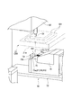
- the work unit M2 is disposed in the area of the third work station S3 as the first assembly station, and is supported so as to be movable up and down from the upper area to the lower area of the transport unit 20.
- the assembling unit 30 disposed at a position overlapping the holding portion 21a (of the rotary table 21) in the vertical direction Z, the elevating drive unit 40 for elevating and driving the assembling unit 30, and the lower region of the transport unit 20
- the component supply unit 50 and the like are arranged to define a component supply position.
- the assembly unit 30 is provided at an upper position of the rotary table 21 (above the work position), and the assembly object W ⁇ b> 1 positioned at the work position is assembled.
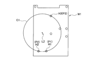
- Parts supply unit corresponding from below to assembly positions (screw holes) H1, H2, H3 of the assembly object W1 positioned at the standby position and work position corresponding to the positions (screw holes) H1, H2, H3 from above 50 parts supply positions P1, P2, and P3 supported by the parts supply positions P1, P2, and P3, and the parts (screws) W2 positioned at the parts supply positions P1, P2, and P3 can be received and assembled to the assembly object W1 (screws).
- a plurality of (here, three) assembly tools 31, 32, 33 and assembly tools 31, 32, 33 that extend downward in the vertical direction Z are driven to rotate (and as required). Later causes) rotating lifting mechanism (not shown), and a guided portion 30a (see FIG. 4) which is guided by the guide rails 42 to be described later.
- the three assembling tools 31, 32, and 33 are vertically moved to the three assembling positions (screw holes) H1, H2, and H3 of the assembling object W1 positioned at the working position.
- a predetermined position part supply positions P1, P2, P3 of a part supply unit 50 described later and the vertical direction Z
- a common first circular orbit C1 centered on a predetermined vertical axis L2.
- the assembly unit 30 the assembly tools 31, 32, 33
- the component can be moved from the standby position without interfering with the holding portion 21a.
- the elevating drive unit 40 is an upright frame 41 erected on the fixed base 10 and two guides as guide members provided on the upright frame 41 and extending in the vertical direction Z to guide the guided portion 30 a of the assembly unit 30.
- a rail 42 (see FIG. 4), a lead screw 43 (see FIG. 4) arranged extending in the vertical direction Z inside the guide rail 42, screwed into the lead screw 43 and fixed to the assembly unit 30
- a nut member 44 (see FIG. 4), a drive motor 45 fixed to the upright frame 41 to rotationally drive the lead screw 43, and the like are provided.
- the elevating drive unit 40 is disposed on the stepped portion 12 of the fixed base 10 at a position where it does not interfere with the rotary table 21.
- the assembly unit 30 (the tip of the assembly tools 31, 32, 33) at the standby position above the rotary table 21 is supplied to the parts below the rotary table 21.
- the drive motor 45 is lowered to the positions P1, P2, and P3 and rotated in the other direction, it is raised from the component supply positions P1, P2, and P3 to the upper standby position. That is, when the assembling tools 31, 32, and 33 are in positions where the assembling tools 31, 32, and 33 face the opening between the holding portions 21a of the rotary table 21, the lifting / lowering driving unit 40 is positioned at the component supply positions P1, P2, and P3.
- the assembly tools 31, 32, 33 are lowered from the standby position to receive the component W2, and are raised to the standby position after receiving the part W2, and then the assembly tools 31, 32 are attached to the assembly object W1 positioned at the work position. , 33 is moved down so as to approach and the assembly unit 30 is driven up and down to assemble the component W2.
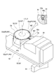
- the component supply unit 50 includes an upright frame 51 erected on the stepped portion 12 of the fixed base 10, a horizontal frame 52 fixed to the upright frame 51, and a horizontal frame 52.
- a circular rotating member 53 that is rotatably supported around the vertical axis L2 above, a drive motor (not shown) as a drive mechanism that rotationally drives the circular rotating member 53, and a horizontal frame 52 that is disposed on the outer periphery of the circular rotating member 53.
- a housing case 56 and the like for housing are provided.
- the circular rotating member 53 is disposed in a lower region than the rotary table 21, has a circular outer contour, and is coaxial with the center of the first circular track C1 and on the second circular track C2 having the same diameter.
- a plurality (three in this case) are formed so as to open upward and radially outward at the peripheral edge thereof to accommodate the component W2. It is formed so as to have a component accommodating portion 53a.
- the component introduction member 55 is formed so as to define a component introduction passage 55 a that guides the component W ⁇ b> 2 that is biased toward the component housing portion 53 a from the outside in the radial direction of the circular rotating member 53.
- the cylindrical fixing member 54 has the same height (or almost the same height) as the circular rotating member 53, and introduces components at one place in the circumferential direction and at the same height as the component accommodating portion 53 a of the circular rotating member 53.
- There is an opening 54a into which the member 55 is inserted that is, an opening that allows the component introduction passage 55a to communicate with the component housing portion 53a when the circular rotation member 53 is at a predetermined rotation angle position).
- the component W2 is supplied (pushed in) to the component accommodating portion 53a.
- the component W2 is not supplied to the component accommodating portion 53a when the component accommodating portion 53a is in a position not facing the component introduction passage 55a.
- the component W2 seated and accommodated in the component accommodating portion 53a is regulated by the inner peripheral surface (upper edge) of the cylindrical fixing member 54. That is, the cylindrical fixing member 54 allows the component W2 to be introduced into the component accommodating portion 53a when the component accommodating portion 53a faces the component introduction passage 55a as the circular rotating member 53 rotates, and the component accommodating portion.
- 53a deviates from the component introduction passage 55a the introduction of the component W2 into the component accommodating portion 53a is blocked and the dropping of the component W2 accommodated in the component accommodating portion 53a is restricted.
- the component W2 continuously supplied through the component introduction passage 55a of the component introduction member 55 has a plurality of (three) components by appropriately rotating the circular rotation member 53 with respect to the cylindrical fixing member 54.
- the components are sequentially accommodated and held in the component accommodating portion 53a, and the circular rotating member 53 stops at a predetermined rotation angle, thereby being positioned at the component supply positions P1, P2, and P3, respectively.
- the component supply unit 50 has a structure including the circular rotating member 53 having the component accommodating portion 53a, the component introducing member 55, the cylindrical fixing member 54, and the drive motor that rotationally drives the circular rotating member 53. It is possible to achieve simplification, integration, miniaturization, etc. of the structure while supplying the component W2.
- the work unit M3 is arranged in the area of the fourth work station S4 as the second assembly station, and is supported so as to be movable up and down from the upper area to the lower area of the transport unit 20 and work.
- the assembling unit 30 ′ arranged at a position overlapping the holding portion 21 a (of the rotary table 21) in the vertical direction Z, the elevating drive unit 40 for elevating and driving the assembling unit 30 ′, and the transport unit 20
- a component supply unit 50 ′ and the like arranged in the lower region and defining a component supply position are provided.
- the assembly unit 30 ′ is provided at an upper position (above the work position) of the rotary table 21 and is a set of the assembly object W ⁇ b> 1 positioned at the work position.
- the component W2 supported by the component supply positions P4, P5 and P6 of the unit 50 ′ so as to be movable up and down and positioned at the component supply positions P4, P5 and P6 is received and assembled (screwed) into the assembly target W1.
- the plurality of (in this case, three) assembly tools 31, 32, 33 and assembly tools 31, 32, 33 that extend downward in the vertical direction Z are rotationally driven (and moved up and down as necessary).
- a rotation elevating mechanism (not shown), and a guided portion 30a (see FIG. 4) guided by the guide rail 42.
- the three assembling tools 31, 32, and 33 are vertically moved to three assembling positions (screw holes) H4, H5, and H6 of the assembling object W1 positioned at the working position.
- Predetermined positions passing on a common first circular orbit C1 ′ centered on a predetermined vertical axis L3 so as to correspond in the direction Z part supply positions P4, P5, P6 of a part supply unit 50 ′ described later and the vertical direction
- Part supply positions P4, P5, P6 of a part supply unit 50 ′ described later and the vertical direction Part supply positions P4, P5, P6 of a part supply unit 50 ′ described later and the vertical direction
- the assembly unit 30 ′ (assembly tool 31, 32, 33) is located at a position facing the opening between the holding portions 21 a of the rotary table 21, the assembly unit 30 ′ can be moved from the standby position without interfering with the holding portion 21 a. It is formed so that it can be lowered to the component supply positions P4, P5, P6 of the component supply unit 50 '(its shape and arrangement position are adjusted).
- the assembly unit 30 ′ (the tips of the assembly tools 31, 32, and 33) is driven by the elevating drive unit 40 so that the standby position above the rotary table 21 and the component supply position below the rotary table 21. Can be moved up and down.
- the component supply unit 50 ′ includes an upright frame 51, a horizontal frame 52, a circular rotation member 53 ′ that is rotatably supported on the horizontal frame 52 around the vertical axis L 3, and a circular rotation member.
- a drive motor (not shown) that rotationally drives 53 ′, a cylindrical fixing member 54, a component introduction member 55, a housing case 56, and the like are provided.
- the circular rotating member 53 ′ is disposed in a lower region than the rotary table 21, has a circular outer contour, is coaxial with the center of the first circular track C1 ′, and has the same diameter as the second circular track C2 ′.
- a plurality in this case, 3) formed so as to be open upward and radially outward at the periphery thereof to accommodate the component W2.
- Component housing portion 53a The components W2 continuously supplied through the component introduction passage 55a of the component introduction member 55 are plural (three) by appropriately rotating the circular rotation member 53 ′ relative to the cylindrical fixing member 54. Are sequentially accommodated and held in the component accommodating portion 53a, and the circular rotating member 53 'stops at a predetermined rotation angle, thereby being positioned at the component supply positions P4, P5, and P6, respectively.
- the work unit M4 is disposed in the area of the fifth work station S5 as the third assembly station, and is supported so as to be movable up and down from the upper area to the lower area of the transport unit 20 and work.
- the assembling unit 60 arranged at a position overlapping the holding portion 21a (of the rotary table 21) in the vertical direction Z, the elevating drive unit 40 for elevating and driving the assembling unit 60, and the lower region of the transport unit 20
- the two component supply units 70, the assembly unit 60 (and the lifting drive unit 40), and the two component supply units 70 which are disposed in the horizontal direction and define the component supply position, are held in the horizontal direction with respect to the fixed base 10.
- a movable base 80 that moves two-dimensionally is provided.
- the assembly unit 60 is provided at an upper position (above the work position) of the rotary table 21 and a plurality of assembly objects W ⁇ b> 1 positioned at the work position.
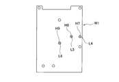
- the assembly position (screw hole) H7, H8, H9 of two assembly positions (screw holes) H7, H8 from the upper side corresponding to the assembly position and the assembly position of the assembly object W1 positioned at the work position (from above) Screw holes) H7, H8, and H9, two assembly positions (screw holes) H7 and H8 are supported in such a manner that they can be moved up and down between the component supply positions P7 and P8 of the component supply unit 70 corresponding from below.
- a plurality (in this case,) extending downward in the vertical direction Z so that the parts W2 positioned at the positions P7 and P8 are received and assembled (screwed) into the assembly positions (screw holes) H7 and H8 of the assembly object W1.
- the assembling tools 31 and 32, the assembling tools 31 and 32 are rotated and driven (and moved up and down as needed), and a guided portion 30a guided by the guide rail 42 (see FIG. 4). ).
- the two assembly tools 31 and 32 are assembly objects positioned at the working position. Positions passing through predetermined vertical axes L4 and L5 so as to correspond in the vertical direction Z to two assembly positions (screw holes) H7 and H8 among the three assembly positions (screw holes) H7, H8 and H9 of W1. Is arranged. Further, when the assembly unit 60 (the assembly tools 31 and 32) is located at a position facing the opening between the holding portions 21a of the rotary table 21, the component supply unit can be moved from the standby position without interfering with the holding portion 21a.
- the assembly unit 60 (the tips of the assembly tools 31 and 32) is driven between the standby position above the rotary table 21 and the component supply position below the rotary table 21 by driving of the elevating drive unit 40. Can be moved up and down.
- the two component supply units 70 are erected on an upright frame 71 and a horizontal frame fixed on the upright frame 71, respectively.
- a slide member 73 as a movable member supported so as to be reciprocally movable (slidable) in the horizontal direction on the frame 72 and the horizontal frame 72, and a drive mechanism (not shown) for reciprocally driving (sliding) the slide member 73;
- a component introduction passage 75a for introducing the component W2 into the slide member 73 (a component housing portion 73a described later) and a wall surface 75b adjacent to one side surface of the slide member 73 and a component introduction member 75 fixed on the horizontal frame 72 are defined.
- the parts W2 are sequentially sent out while being urged toward the slide member 73 through the part introduction passage 75a of the part introduction member 75.
- Accommodating case 76 for accommodating the W2, and a lock mechanism (not shown) or the like for locking the mounting angle in the horizontal plane relative to the horizontal frame 72 of the slide member 73 and the component introduction member 75 at an arbitrary angle.
- Each of the two slide members 73 is disposed in a lower region than the rotary table 21, and an array of a plurality of assembly positions of the assembly target object W1 (see FIG. 10A) positioned at the work position by the drive mechanism.
- One component housing portion formed so as to be slidable in a linear direction D1 in a horizontal plane parallel to the direction and opened upward and on the side facing the wall surface 75b of the component introduction member 75 so as to accommodate the component W2.
- 73a and by positioning the component accommodating portion 73a at a predetermined slide position, component supply positions P7 and P8 are defined on predetermined vertical axes L4 and L5, respectively.
- the component introduction member 75 is formed at the same height (or substantially the same height) as the slide member 73, and has a component introduction passage 75a at the same height position as the component storage portion 73a.
- the component housing portion 73a is supplied (pushed in) and seated, and the component housing portion 73a is seated.
- the component W2 is not supplied to the component housing portion 73a when the component introduction passage 75a is not located. Further, the component W2 seated and accommodated in the component accommodating portion 73a is regulated by the wall surface 75b of the component introduction member 75.
- the component introduction member 75 defines a component introduction passage 75a that guides the component W2 toward the component accommodation portion 73a, and the component introduction portion 75a faces the component introduction passage 75a as the slide member 73 moves. It is formed so as to demarcate a wall surface 75b that permits introduction of the component W2 into the housing portion 73a and restricts dropping of the component W2 housed in the component housing portion 73a when the component housing portion 73a deviates from the component introduction passage 75a. ing.
- the component W2 continuously supplied through the component introduction passage 75a of the component introduction member 75 is accommodated in the component accommodation portion 73a as the slide member 73 appropriately moves relative to the component introduction member 75.
- the slide member 73 is held and moved by a predetermined amount and stopped, so that it is positioned at the component supply positions P7 and P8, respectively.
- the component supply unit 70 has a structure including the slide member 73 having the component accommodating portion 73a, the component introduction member 75, and the drive mechanism for slidingly driving the slide member 73, a long component supply unit such as a conveyor is provided. Compared to, it is possible to achieve simplification, consolidation, miniaturization, and the like of the structure.
- the movable base 80 supports the first movable frame 81 that fixes the upright frames 41 and 71 in a standing manner, and supports the first movable frame 81 so as to reciprocate in a first direction D2 in a horizontal plane.
- the second movable frame 82, the support frame 83 that supports the second movable frame 82 so as to reciprocate in a second direction D3 perpendicular to the first direction D2 in the horizontal plane, and the first movable frame 81 are driven in the first direction D2.
- a first drive mechanism (not shown), a second drive mechanism (not shown) that drives the second movable frame 82 in the second direction D3, and a lock mechanism (not shown) that locks the movable base 80 at a predetermined position with respect to the fixed base 10. Etc.).
- the transport unit 20 is arranged on the fixed base 10
- the assembly unit 60 and the component supply unit 70 are arranged on the movable base 80 that can move two-dimensionally in the horizontal plane with respect to the fixed base 10. Therefore, the relative positional relationship between the assembly unit 60 (the assembly tools 31, 32) and the component supply unit 70 (the component supply positions P7, P8) is maintained.
- the movable base 80 is appropriately moved and positioned at a predetermined position, thereby causing a positional shift with respect to various assembly targets W1 having different assembly positions. Parts can be assembled with high accuracy without any problems.
- the work unit M5 is disposed in the area of the sixth work station S6 as the fourth assembly station, and is supported so as to be movable up and down from the upper area to the lower area of the transport unit 20 and work.
- the assembling unit 60 ′ disposed at a position overlapping the holding portion 21 a (of the rotary table 21) in the vertical direction Z, the elevating drive unit 40 for elevating and driving the assembling unit 60 ′, and the transport unit 20
- One component supply unit 70 which is disposed in the lower region and demarcating the component supply position, the assembly unit 60 ′ (and the lifting drive unit 40) and the component supply unit 70 are held together to be horizontal with respect to the fixed base 10.
- a movable base 80 or the like that moves two-dimensionally.
- the assembly unit 60 ′ is provided at an upper position (above the work position) of the rotary table 21, and an assembly position of the assembly target object W ⁇ b> 1 positioned at the work position ( Assembling positions (screw holes) H7, H8 of the assembly target object W1 positioned at the working position and the standby position corresponding to the assembling position (screw hole) H9 from among the screw holes H7, H8, H9 , H9, and receives the component W2 that is supported at the component supply position P9 and is positioned at the component supply position P9 from the lower side to the component supply position P9 of the component supply unit 70 corresponding to one assembly position (screw hole) H9.
- One assembly tool 31 that extends downward in the vertical direction Z so as to be assembled (screwed) into the assembly position (screw hole) H9 of the assembly object W1 and rotationally drive the assembly tool 31 (with Lift is allowed) rotating lifting mechanism in accordance with the requirements (not shown), and a guided portion 30a (see FIG. 4) which is guided by the guide rail 42.
- one assembling tool 31 has one assembling position (screw hole) H9 among three assembling positions (screw holes) H7, H8, H9 of the assembling object W1. Is arranged at a position passing through a predetermined vertical axis L6. Further, when the assembly unit 60 ′ (assembly tool 31) is located at a position facing the opening between the holding portions 21 a of the rotary table 21, the component supply unit 70 can be moved from the standby position without interfering with the holding portion 21 a. It is formed so that it can be lowered to the component supply position P9 (with its shape and arrangement position adjusted).
- the assembly unit 60 ′ (the tip of the assembly tool 31) is driven between the standby position above the rotary table 21 and the component supply position below the rotary table 21 by driving of the elevating drive unit 40. It can be moved up and down. Further, the component supply unit 70 supplies the component W2 to the component supply position P9 on the vertical axis L6.
- the configurations and operations of the lifting drive unit 40, the component supply unit 70, and the movable base 80 are basically the same as those included in the work unit M4, and thus description thereof is omitted.
- the work unit M6 is arranged in the area of the seventh work station S7, and the assembly object in which the component W2 is assembled and positioned and held on the transport unit 20 (the holding portion 21a thereof).
- An affixing unit that affixes a label on which predetermined information is printed to W1 and a detection unit that detects whether or not the component (screw) W2 is lifted are provided.
- the work unit M7 is arranged in the area of the eighth work station S8, and the component W2 is assembled and a label is attached to the work unit M7 so as to be positioned on the transport unit 20 (the holding part 21a).
- a bar code reader or the like can be adopted.
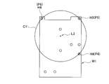
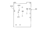
- the assembly position (screw hole) of the assembly object W1 assembled by the assembly units 60 and 60 ′ is limited to the assembly positions (screw holes) H7, H8, and H9 shown in FIG. 10A.
- the assembly positions (screw holes) H7, H8, H9 shown in FIG. 10A to FIG. 10B are shown. Assembling positions (screw holes) can be easily changed to H10, H11, and H12.
- This is performed based on the control signal of the control unit (control means).
- the work of handing the assembly object W1 with the lid placed on the main body case to the holding unit 21a of the transport unit 20 and the part W2 as described later are performed manually by the operator.
- An unloading operation for taking out the completed product after assembling from the holding portion 21a is performed.
- the delivery operation of the assembly target W1 and the removal operation of the finished product are performed each time the rotary table 21 is rotated by a predetermined angle (22.5 degrees ⁇ 2) and stopped.
- the assembly target W1 is positioned at the second work station S2, as shown in FIG.
- information (model, type, etc.) attached to the assembly object W1 is read by the work unit M1 (information reading unit), the position where the part W2 is to be attached is determined, and control is performed. Sent to the unit. This information reading operation is performed each time the turntable 21 is rotated by a predetermined angle (22.5 degrees ⁇ 2) and stopped.
- the assembly unit 30 (assembly tool 31, 32, 33) face the opening of the turntable 21, and directly face the component W2 supplied to the component supply positions P1, P2, P3 of the component supply unit 50.
- the assembling unit 30 descends from the standby position to a region below the rotary table 21, receives the component W2 at the tip, and again the assembling unit 30 (the assembling unit 31). , 32, 33) rises to a standby position above the rotary table 21 and stands by.
- the component receiving operation by the assembling unit 30 is performed every time the rotary table 21 is rotated by a predetermined angle (22.5 degrees ⁇ 2) and stopped. Further, the supply operation of the component W2 to the component supply positions P1, P2, P3 by the component supply unit 50 is performed until the assembly unit 30 receives the component W2 next time.
- the assembly target object W1 (holding portion 21a) is moved to the work position of the third work station S3. Is positioned.
- the assembling unit 30 (the assembling tools 31, 32, 33) is lowered by a predetermined amount and then driven to rotate.
- the component W2 is assembled to the assembly object W1. (Screw holes) Assemble (screw) into H1, H2, and H3.
- the assembling unit 30 (the assembling tools 31, 32, 33) rises and stops at the standby position.
- the parts assembling work by the assembling unit 30 is performed every time the rotary table 21 is rotated by a predetermined angle (22.5 degrees ⁇ 2) and stopped.
- the assembly unit 30 ′ (assembly tool 31) of the fourth work station S4. , 32, 33) face the opening of the rotary stable 21, and directly face the component W2 supplied to the component supply positions P4, P5, P6 of the component supply unit 50 ′.
- the assembling unit 30 ′ (the assembling tools 31, 32, 33) descends from the standby position to a region below the rotary table 21, and receives the part W2 at the tip thereof.
- the assembling unit 30 ′ (assembling again)
- the tools 31, 32, 33) rise to a standby position above the rotary table 21 and wait.
- the component receiving operation by the assembly unit 30 ′ is performed every time the rotary table 21 stops after rotating by a predetermined angle (22.5 degrees ⁇ 2). Further, the supply operation of the component W2 to the component supply positions P4, P5, P6 by the component supply unit 50 ′ is performed until the assembly unit 30 ′ next receives the component W2.
- the assembly target object W1 (holding portion 21a) is moved to the work position of the fourth work station S4. Is positioned.
- the assembling unit 30 ′ (the assembling tools 31, 32, 33) is lowered by a predetermined amount and then driven to rotate, and as shown in FIG. 9B, the component W2 is assembled to the assembling object W1. Assembling positions (screw holes) H4, H5, H6 are assembled (screwed).
- the assembling unit 30 ′ (the assembling tools 31, 32, 33) rises and stops at the standby position.
- the component assembling work by the assembling unit 30 ′ is performed every time the rotary table 21 rotates and stops at a predetermined angle (22.5 degrees ⁇ 2).
- the assembly unit 60 (assembly tool 31,. 32) faces the opening of the turntable 21 and directly faces the component W2 supplied to the component supply positions P7 and P8 of the component supply unit 70. Then, the assembling unit 60 (the assembling tools 31 and 32) descends from the standby position to a region below the rotary table 21 and receives the part W2 at its tip, and again, the assembling unit 60 (the assembling tools 31 and 32). ) Rises to a standby position above the rotary table 21 and stands by.
- the component receiving operation by the assembling unit 60 is performed every time the turntable 21 is rotated by a predetermined angle (22.5 degrees ⁇ 2) and stopped. Further, the supply operation of the component W2 to the component supply positions P7 and P8 by the component supply unit 70 is performed until the assembly unit 60 next receives the component W2.
- the assembly target W1 is positioned at the work position of the fifth work station S5 as shown in FIG.
- the assembling unit 60 (the assembling tools 31 and 32) is lowered by a predetermined amount and then driven to rotate.
- the component W2 is assembled to the assembly position (screw). Hole) Install (screw) into H7 and H8.
- the assembling unit 60 (the assembling tools 31, 32) rises and stops at the standby position.
- the parts assembling work by the assembling unit 60 is performed every time the rotary table 21 is rotated by a predetermined angle (22.5 degrees ⁇ 2) and stopped.
- the assembly unit 60 ′ (assembly tool 31) of the sixth work station S6. ) Faces the opening of the rotary table 21 and directly faces the component W2 supplied to the component supply position P9 of the component supply unit 70. Then, the assembling unit 60 ′ (the assembling tool 31) descends from the standby position to a region below the rotary table 21 and receives the part W2 at its tip, and the assembling unit 60 ′ (the assembling tool 31) again. Ascend to the standby position above the rotary table 21 and wait.
- the component receiving operation by the assembly unit 60 ' is performed every time the turntable 21 is rotated by a predetermined angle (22.5 degrees ⁇ 2) and stopped. Further, the supply operation of the component W2 to the component supply position P9 by the component supply unit 70 is performed until the assembly unit 60 ′ next receives the component W2.
- the assembly target W1 is positioned at the work position of the sixth work station S6 as shown in FIG.
- the assembling unit 60 ′ (the assembling tool 31) is lowered by a predetermined amount and then driven to rotate.
- the component W2 is assembled to the assembly object W1 (screw hole). ) Assemble (screw) into H9.
- the assembling unit 60 ′ (the assembling tool 31) moves up and stops at the standby position.
- the component assembling work by the assembling unit 60 ' is performed every time the rotary table 21 is rotated by a predetermined angle (22.5 degrees x 2) and stopped.
- the turntable 21 rotates clockwise by a predetermined angle (22.5 degrees ⁇ 2) and stops, the assembly target object W1 is positioned at the eighth work station S8 as shown in FIG. Then, in the eighth work station S8, the work unit M7 (information reading unit) reads the information on the label of the assembly object W1 to which the part W2 is assembled and the label is attached, and the information is sent to the control unit. It is done. This information reading operation is performed each time the turntable 21 is rotated by a predetermined angle (22.5 degrees ⁇ 2) and stopped.
- the assembly position (screw hole) for assembling the part W2 is one of the three assembly positions (screw holes) H7, H8, H9.
- the assembly positions (screw holes) H7, H8 are changed from the two assembly positions (screw holes) H7, H8 to two assembly positions (screw holes) H7, H9 or H8, H9, or the assembly in which the part W2 is assembled at the sixth work station S6.
- the movable base 80 is appropriately moved to attach the assembling unit 60, 60 'and the component supply unit 70 are positioned at predetermined positions in the horizontal plane.
- the assembling units 30, 30 ′, 60, 60 ′ are disposed so as to be movable up and down from the upper region to the lower region of the transport unit 20, and the component supply position is disposed in the lower region of the transport unit 20. Since the component supply units 50, 50 'and 70 that define P1 to P3, P4 to P6, P7 and P8, and P9 are arranged, the space in the vertical direction Z can be used effectively, the structure can be simplified, The installation area of the apparatus can be reduced (space saving) while achieving the integration of the structure and the like.
- the structure of the elevating drive unit 40 can be simplified, and errors due to movement in the horizontal direction do not occur. Therefore, there are few mechanical errors, a minute part (for example, a screw etc.) can be assembled with high accuracy, and the assembly units 30, 30 ′, 60, 60 ′ perform only the raising / lowering operation, and the component W2 Since reception and assembly are performed, useless movement can be abolished, and handling time required from reception of the part W2 to assembly can be shortened.
- a minute part for example, a screw etc.
- the movable base 80 is appropriately moved and positioned at a predetermined position, thereby causing a positional shift with respect to various assembly targets W1 having different assembly positions.
- Parts can be assembled with high accuracy without any problems. Furthermore, it is not possible to assemble at a time by assembling the part W2 in a plurality of assembling stations (the third working station S3, the fourth working station S4, the fifth working station S5, and the sixth working station S6). Such a plurality of parts W2 can be assembled smoothly and efficiently, and the operating efficiency can be improved.
- the component W2 is supplied to the component supply position corresponding to the assembly position of the assembly target object W1 positioned at the work position from below and corresponds to the work position from above.
- the assembly tools 31, 32, 33 are lowered between the standby position and the component supply position to receive the component W2 positioned at the component supply position, and then are raised again to the standby position.
- W1 is conveyed and positioned at the work position, and the assembling tools 31, 32, 33 are lowered toward the assembling position of the assembling object W1 positioned at the working position, and the part W2 is set as the assembling object W1.
- a part assembling method to be assembled is applied. According to this assembling method, it is possible to eliminate useless operations, reduce mechanical errors, assemble minute parts to an assembling object with high accuracy, and achieve a high operating rate.
- the present invention is not limited to a mode in which openings are defined between the radially projecting holding portions 21a, and other modes may be adopted.
- the conveyance unit 20 containing the rotation table 21 was employ
- adopted as a conveyance unit At least 1 holding
- a transport conveyor equipped with a drive mechanism or the like that moves the holding portion along a transport track extending in a predetermined direction and that is positioned at a work position is adopted.
- a component supply unit is disposed below the transport conveyor, and the component supply unit.
- a configuration may be adopted in which the assembly unit is placed on the upper side of the conveyor so as to be opposed to each other.
- the component supply units 50 and 50 ′ including the circular rotating members 53 and 53 ′ having the component accommodating portion 53 a are shown as the component supply units.
- the present invention is not limited to this, and components are supplied.
- a rotating member having another form may be adopted.
- the component supply unit 70 including the slide member 73 having the component accommodating portion 73a is shown as the component supply unit.
- the present invention is not limited to this, and the component supply position for supplying and positioning the component is not limited thereto. As long as it moves linearly in a predetermined direction in a horizontal plane, other forms of movable members may be employed.
- a screw is shown as the component W2
- a screw tightening tool (driver) is shown as an assembly tool of the assembly unit.
- the present invention is not limited to this, and a press-fit pin is adopted as the component W2.
- a press-fit rod may be employed as the assembly tool, or another component and another assembly tool according to the assembly of the component may be employed.
- the delivery work of the assembly target object W1 and the work of taking out the finished product in one work station S1 may be automatically performed using a conveyor, a transfer unit, and the like.
- the component supply apparatus and method of the present invention achieves the simplification of the structure, the integration of the structure, the reduction in cost, the increase in the operating rate, and the like, while reducing the installation area of the apparatus (saving space). ) And can effectively use the space in factories, etc., and can flexibly support different models, and there are few mechanical errors and it is possible to assemble minute parts with high precision. In the electrical and mechanical fields, it is also useful for assembling child parts to parent parts.
Landscapes
- Engineering & Computer Science (AREA)
- Mechanical Engineering (AREA)
- Automatic Assembly (AREA)
Applications Claiming Priority (2)
| Application Number | Priority Date | Filing Date | Title |
|---|---|---|---|
| JP2009108583A JP5313759B2 (ja) | 2009-04-28 | 2009-04-28 | 部品組付け装置 |
| JP2009-108583 | 2009-04-28 |
Publications (1)
| Publication Number | Publication Date |
|---|---|
| WO2010125912A1 true WO2010125912A1 (ja) | 2010-11-04 |
Family
ID=43032065
Family Applications (1)
| Application Number | Title | Priority Date | Filing Date |
|---|---|---|---|
| PCT/JP2010/056640 Ceased WO2010125912A1 (ja) | 2009-04-28 | 2010-04-14 | 部品組付け装置及び方法 |
Country Status (2)
| Country | Link |
|---|---|
| JP (1) | JP5313759B2 (enExample) |
| WO (1) | WO2010125912A1 (enExample) |
Cited By (5)
| Publication number | Priority date | Publication date | Assignee | Title |
|---|---|---|---|---|
| CN104070350A (zh) * | 2013-03-28 | 2014-10-01 | 爱司帝光电科技(苏州)有限公司 | 组装设备与组装方法 |
| CN110524231A (zh) * | 2019-09-06 | 2019-12-03 | 广汽丰田发动机有限公司 | 一种拧松机 |
| CN111203712A (zh) * | 2020-03-10 | 2020-05-29 | 杨浩 | 一种玻璃升降器叉臂自动组装设备 |
| CN112959064A (zh) * | 2021-04-21 | 2021-06-15 | 深圳市合力士机电设备有限公司 | 轴承座移料组装机构及其组装方法 |
| CN113909886A (zh) * | 2021-11-04 | 2022-01-11 | 中国兵器装备集团自动化研究所有限公司 | 一种玻璃贴合压装设备 |
Families Citing this family (4)
| Publication number | Priority date | Publication date | Assignee | Title |
|---|---|---|---|---|
| KR101422416B1 (ko) | 2013-10-23 | 2014-07-23 | 엘지전자 주식회사 | 부품 공급 장치 |
| CN111791054B (zh) * | 2020-07-13 | 2021-08-10 | 深圳市优迪泰自动化科技有限公司 | 摇杆弹片装配机 |
| CN111958217B (zh) * | 2020-08-16 | 2021-12-03 | 济南奥普瑞思智能装备有限公司 | 一种用于装配逆变器的接电模块与底板的机器人以及装配方法 |
| CN111958237B (zh) * | 2020-08-16 | 2021-08-31 | 瑞安市恩驰电子科技有限公司 | 一种用于装配逆变器的接电机构的机器人以及方法 |
Citations (1)
| Publication number | Priority date | Publication date | Assignee | Title |
|---|---|---|---|---|
| JP2007222977A (ja) * | 2006-02-22 | 2007-09-06 | Ricoh Co Ltd | 部品組付け装置 |
Family Cites Families (6)
| Publication number | Priority date | Publication date | Assignee | Title |
|---|---|---|---|---|
| JP2832489B2 (ja) * | 1990-07-23 | 1998-12-09 | スズキ株式会社 | サラ小ネジの自動供給装置 |
| JPH04123597U (ja) * | 1991-02-08 | 1992-11-09 | 富士通テン株式会社 | 部品の自動装着装置 |
| JP3276400B2 (ja) * | 1992-06-12 | 2002-04-22 | 蛇の目ミシン工業株式会社 | 六角穴付き止めネジ自動供給装置 |
| JP3733222B2 (ja) * | 1997-10-06 | 2006-01-11 | キヤノン株式会社 | 物品組み立て装置及び物品組み立て方法 |
| JP3356038B2 (ja) * | 1997-12-10 | 2002-12-09 | 三菱自動車エンジニアリング株式会社 | ストラットアセンブリの組立装置および組立方法 |
| JP4446588B2 (ja) * | 2000-12-13 | 2010-04-07 | 日東精工株式会社 | 部品検査装置 |
-
2009
- 2009-04-28 JP JP2009108583A patent/JP5313759B2/ja active Active
-
2010
- 2010-04-14 WO PCT/JP2010/056640 patent/WO2010125912A1/ja not_active Ceased
Patent Citations (1)
| Publication number | Priority date | Publication date | Assignee | Title |
|---|---|---|---|---|
| JP2007222977A (ja) * | 2006-02-22 | 2007-09-06 | Ricoh Co Ltd | 部品組付け装置 |
Cited By (6)
| Publication number | Priority date | Publication date | Assignee | Title |
|---|---|---|---|---|
| CN104070350A (zh) * | 2013-03-28 | 2014-10-01 | 爱司帝光电科技(苏州)有限公司 | 组装设备与组装方法 |
| CN110524231A (zh) * | 2019-09-06 | 2019-12-03 | 广汽丰田发动机有限公司 | 一种拧松机 |
| CN111203712A (zh) * | 2020-03-10 | 2020-05-29 | 杨浩 | 一种玻璃升降器叉臂自动组装设备 |
| CN111203712B (zh) * | 2020-03-10 | 2022-01-14 | 昆山广振汽车部件有限公司 | 一种玻璃升降器叉臂自动组装设备 |
| CN112959064A (zh) * | 2021-04-21 | 2021-06-15 | 深圳市合力士机电设备有限公司 | 轴承座移料组装机构及其组装方法 |
| CN113909886A (zh) * | 2021-11-04 | 2022-01-11 | 中国兵器装备集团自动化研究所有限公司 | 一种玻璃贴合压装设备 |
Also Published As
| Publication number | Publication date |
|---|---|
| JP5313759B2 (ja) | 2013-10-09 |
| JP2010253647A (ja) | 2010-11-11 |
Similar Documents
| Publication | Publication Date | Title |
|---|---|---|
| JP5313759B2 (ja) | 部品組付け装置 | |
| CN106239144B (zh) | 灵活的装配机械、系统及方法 | |
| CN100448341C (zh) | 基板相关操作执行设备、用于基板相关操作执行设备的操作执行头、基板相关操作执行系统以及操作执行头使用准备方法 | |
| CN101400478B (zh) | 机床和控制机床的方法 | |
| CN113858818A (zh) | 打标系统 | |
| TW200924904A (en) | Method and apparatus for assembling a complex product in a parallel process system | |
| EP0637199A1 (en) | Automatic electronic parts mounting apparatus | |
| JPWO2004066701A1 (ja) | 対回路基板作業機およびそれに対する構成要素の供給方法 | |
| CN110103017B (zh) | 磁系统半自动组装设备 | |
| US11396076B2 (en) | Modular automated table-top production pod | |
| CN113500364A (zh) | 手写笔自动组装系统及控制方法 | |
| CN114566450B (zh) | 晶圆上料装置 | |
| CN217296334U (zh) | 可旋翻转上下料装置 | |
| CN116101753A (zh) | 一种自动上下料设备 | |
| CN214445323U (zh) | 一种可不停机上下料的面板加工设备 | |
| CN210878122U (zh) | 全自动蓝宝石切割设备 | |
| CN114435913B (zh) | 多功能摄像头组件自动化贴附设备 | |
| CN118405461A (zh) | 第二输送装置及pcb板输送系统 | |
| CN218771672U (zh) | 定子装配设备 | |
| US20080019804A1 (en) | Container Opening-Closing Apparatus and Container-Placement-Position Adjustment Method for the Same | |
| CN212043446U (zh) | 锁附装置 | |
| CN220411975U (zh) | 一种石英晶片自动收料盘机 | |
| CN210255409U (zh) | Pcb板中转装置及pcb板输送系统 | |
| JP4182165B2 (ja) | 電子部品の自動組立装置 | |
| CN114435889A (zh) | 双层输送线 |
Legal Events
| Date | Code | Title | Description |
|---|---|---|---|
| 121 | Ep: the epo has been informed by wipo that ep was designated in this application |
Ref document number: 10769611 Country of ref document: EP Kind code of ref document: A1 |
|
| NENP | Non-entry into the national phase |
Ref country code: DE |
|
| 122 | Ep: pct application non-entry in european phase |
Ref document number: 10769611 Country of ref document: EP Kind code of ref document: A1 |