WO2010125912A1 - 部品組付け装置及び方法 - Google Patents
部品組付け装置及び方法 Download PDFInfo
- Publication number
- WO2010125912A1 WO2010125912A1 PCT/JP2010/056640 JP2010056640W WO2010125912A1 WO 2010125912 A1 WO2010125912 A1 WO 2010125912A1 JP 2010056640 W JP2010056640 W JP 2010056640W WO 2010125912 A1 WO2010125912 A1 WO 2010125912A1
- Authority
- WO
- WIPO (PCT)
- Prior art keywords
- component
- assembly
- unit
- assembling
- component supply
- Prior art date
- Legal status (The legal status is an assumption and is not a legal conclusion. Google has not performed a legal analysis and makes no representation as to the accuracy of the status listed.)
- Ceased
Links
Images


Classifications
-
- B—PERFORMING OPERATIONS; TRANSPORTING
- B23—MACHINE TOOLS; METAL-WORKING NOT OTHERWISE PROVIDED FOR
- B23P—METAL-WORKING NOT OTHERWISE PROVIDED FOR; COMBINED OPERATIONS; UNIVERSAL MACHINE TOOLS
- B23P19/00—Machines for simply fitting together or separating metal parts or objects, or metal and non-metal parts, whether or not involving some deformation; Tools or devices therefor so far as not provided for in other classes
- B23P19/04—Machines for simply fitting together or separating metal parts or objects, or metal and non-metal parts, whether or not involving some deformation; Tools or devices therefor so far as not provided for in other classes for assembling or disassembling parts
- B23P19/06—Screw or nut setting or loosening machines
-
- B—PERFORMING OPERATIONS; TRANSPORTING
- B23—MACHINE TOOLS; METAL-WORKING NOT OTHERWISE PROVIDED FOR
- B23P—METAL-WORKING NOT OTHERWISE PROVIDED FOR; COMBINED OPERATIONS; UNIVERSAL MACHINE TOOLS
- B23P19/00—Machines for simply fitting together or separating metal parts or objects, or metal and non-metal parts, whether or not involving some deformation; Tools or devices therefor so far as not provided for in other classes
- B23P19/001—Article feeders for assembling machines
-
- B—PERFORMING OPERATIONS; TRANSPORTING
- B23—MACHINE TOOLS; METAL-WORKING NOT OTHERWISE PROVIDED FOR
- B23P—METAL-WORKING NOT OTHERWISE PROVIDED FOR; COMBINED OPERATIONS; UNIVERSAL MACHINE TOOLS
- B23P21/00—Machines for assembling a multiplicity of different parts to compose units, with or without preceding or subsequent working of such parts, e.g. with program control
- B23P21/004—Machines for assembling a multiplicity of different parts to compose units, with or without preceding or subsequent working of such parts, e.g. with program control the units passing two or more work-stations whilst being composed
- B23P21/006—Machines for assembling a multiplicity of different parts to compose units, with or without preceding or subsequent working of such parts, e.g. with program control the units passing two or more work-stations whilst being composed the conveying means comprising a rotating table
Definitions
- the present invention relates to a part assembling apparatus and method for assembling parts such as electronic parts or mechanical parts, and more particularly, to a part assembling apparatus and method for assembling parts on an assembling object that is intermittently conveyed in a positioned state.
- a work supply unit including an index table that holds a work (assembly object) for fastening screws and intermittently conveys the work, and is arranged at a position separated from the index table in the horizontal direction.
- a screw supply unit that supplies screws, a driver unit (assembly tool) that holds and holds screws supplied by the screw supply unit, and an index table from the screw supply position of the screw supply unit
- a device including a driver unit driving means for driving the driver unit to move up and down and move in the horizontal direction so as to convey the screw to the upper assembly position (screw fastening position) is known (for example, Patent Documents). 1).
- an index table that is disposed substantially at the center and holds a work (assembly target object) and rotates intermittently, and an index table that is disposed in the outer peripheral area of the index table and is freely movable up and down.
- a workpiece supply unit including a chuck that freely rotates and grips a workpiece, a detection unit that is disposed in an outer peripheral region of the index table and detects a position of a rivet hole of the workpiece, and an outer peripheral region of the index table (separate in the horizontal direction)
- a rivet supply index portion (supply unit) that is arranged to supply rivets, a rivet insertion portion that holds a rivet and inserts it into a rivet hole of a workpiece, and a press portion that clamps and crimps the rivet inserted into the workpiece , Inspection unit for inspecting the rivet caulking state, unloading unit for unloading workpieces from the index table, etc.
- Those with is known (e.g., see Patent Document 2).
- components necessary for assembly are supplied at a supply position of a supply unit arranged in the outer peripheral area of the index table, and a driver for assembling the components Parts are supplied by the unit or rivet insertion portion moving horizontally between the supply position on the supply unit and the assembly position on the index table, so that the driver unit or rivet insertion portion is moved in the horizontal direction.
- Drive mechanism is required, and the assembly unit time is lost due to the horizontal movement of the driver unit or the rivet insertion portion.
- a drive mechanism for moving in the horizontal direction is required, there is a possibility that a mechanical positioning error occurs.
- the installation area of the apparatus around the index table is increased.
- the present invention has been made in view of the above-mentioned conventional technology, and the object of the present invention is to simplify the structure, consolidate the structure, reduce the cost, increase the operating rate, etc.
- the space required for factories and other facilities can be used effectively by reducing the installation area of the machine (and saving space), and it can be flexibly adapted to different models, and there are few mechanical errors and high precision of minute parts. It is an object of the present invention to provide a component assembling apparatus and method that can be assembled to a machine.
- the component assembling apparatus of the present invention is arranged below the assembly target positioned at the work position, the transport unit for holding and transporting the assembly target, and positioned at a predetermined work position.
- a component supply unit that demarcates a component supply position corresponding to the assembly position of the object and supplies and positions the component, and a standby unit that is disposed above the assembly target positioned at the work position and corresponds to the assembly position.
- An assembly unit having an assembly tool that is supported so as to be movable up and down between the position and the component supply position and can be assembled to an assembly object by receiving the component positioned at the component supply position, and the assembly tool is in the component supply position It includes a lift drive unit that receives the components positioned in the position and drives the assembly unit to move up and down to be mounted on the assembly object positioned at the work position. .
- the assembly unit having the assembly tool between the standby position above the work position (conveyance unit) and the component supply position below the work position (conveyance unit) is Driven up and down, the assembly tool receives the components supplied to the component supply position (defined by the component supply unit) below the work position (conveyance unit) and rises to the top of the conveyance unit (standby position), After that, when the transport unit holds the object to be assembled and positions it at a predetermined work position where it is transported and parts are assembled, the assembly tool is lowered again and the parts are assembled to the object to be assembled.
- the assembly unit having the assembly tool is arranged above the work position (conveyance unit), and the assembly tool can be moved up and down from the work position (conveyance unit). Since the component supply unit that demarcates the supply position is arranged, the space in the vertical direction can be used effectively, and the installation area of the device can be reduced (saving) while achieving simplification of the structure and integration of the structure. Space). In addition, the assembly unit only moves up and down and does not move in the horizontal direction, so the structure of the lifting drive unit can be simplified, and errors due to movement in the horizontal direction do not occur. (For example, screws) can be assembled with high accuracy. Furthermore, since the assembly unit (assembly tool) only moves up and down to receive and assemble parts, useless movement can be eliminated and handling time required from receipt of parts to assembly is reduced. Can do.
- the assembly tool and the component supply position are arranged on a vertical axis extending in the vertical direction through the assembly position of the assembly object positioned at the work position, and the elevating drive unit includes the assembly tool.
- a configuration including a guide member that guides the assembly unit so as to move up and down along the vertical axis can be adopted. According to this configuration, when the assembling unit is raised and lowered by the elevating drive unit, the assembling unit is guided by the guide member, and the assembling tool is moved down on the vertical axis and positioned at the component supply position. Therefore, the parts can be received with high accuracy.
- the component supply unit includes a plurality of parts on the second circular orbit that is coaxial with the center of the common first circular orbit passing through a plurality of assembling positions of the assembly object positioned at the work position and on the same diameter. And a rotating member that rotates about the same axis, the rotating member having a circular outer contour and a plurality of component supplying positions at the periphery thereof, upward and radially outward.
- the component supply unit includes a circular rotating member, a component introducing member that defines a component introducing path for guiding components from the radial outer side of the circular rotating member toward the component accommodating portion, and introduction of the component into the component accommodating portion.
- a configuration including a cylindrical fixing member that allows the rotation of the circular rotating member and a cylindrical fixing member that allows the rotation of the circular rotating member According to this configuration, the components that are continuously supplied through the component introduction passage of the component introduction member are sequentially transferred to the plurality of component accommodating portions by appropriately rotating the circular rotating member with respect to the cylindrical fixing member.
- the circular rotary member is accommodated and held, and is positioned at the component supply position by stopping at the predetermined rotational position.
- the component supply unit has a structure including a circular rotating member having a component accommodating portion, a component introducing member, a cylindrical fixing member, and a driving mechanism for the circular rotating member, the structure is provided while supplying a plurality of components. Simplification, integration, miniaturization, etc. can be achieved.
- the cylindrical fixing member may have a configuration having an opening that allows the component introduction passage to communicate with the component accommodating portion when the circular rotating member is at a predetermined rotation angle position.
- the simple structure in which the opening is formed in the cylindrical fixing member allows the introduction of the component into the component accommodating portion in cooperation with the rotation of the circular rotating member, and the introduction of the component into the component accommodating portion. Can be cut off.
- the component supply unit defines a component supply position and is supported and movable linearly in a predetermined direction parallel to the arrangement direction of the plurality of assembly positions of the assembly target objects positioned at the work position.
- the movable member includes a component receiving portion formed so as to open upward and horizontally in the horizontal direction perpendicular to the predetermined direction so as to define a component supply position, and to slide in a predetermined direction.
- a configuration consisting of possible slide members can be employed. According to this configuration, the movable member (sliding member) is appropriately moved in a predetermined direction while achieving simplification and downsizing of the component supply unit, so that the component supply position corresponding to the plurality of assembly positions can be obtained from below. Parts can be supplied and positioned.
- the component supply unit defines a slide member and a component introduction passage for guiding the component toward the component accommodating portion, permits introduction of the component into the component accommodating portion, and is used for the component accommodated in the component accommodating portion. It is possible to adopt a configuration including a component introduction member that defines a wall surface that regulates dropping and a drive mechanism that slide-drives the slide member. According to this configuration, the components that are continuously supplied through the component introduction passage of the component introduction member are accommodated in the component accommodation portion by appropriately moving the slide member relative to the wall surface of the component introduction member. The slide member is held at a predetermined position and positioned at the component supply position.
- the component supply unit has a structure including a slide member having a component accommodating portion, a component introduction member, and a drive mechanism for the slide member, the structure is simplified and integrated while continuously supplying components. Thus, miniaturization and the like can be achieved.
- the said structure WHEREIN The structure which has a some assembly
- a screw tightening tool such as a driver, a press-fit tool, etc.
- the above configuration further includes a fixed base provided with the transport unit and a movable base that can move two-dimensionally in a horizontal plane with respect to the fixed base, and the movable base holds the assembly unit and the component supply unit. And a first movable frame supported so as to be movable in a first direction within a horizontal plane, and a second movable frame supported so as to be movable in a second direction perpendicular to the first direction within the horizontal plane while holding the first movable frame.
- a configuration including a frame and a support frame provided on the fixed base and movably supporting the second movable frame can be employed.
- the transport unit is arranged on the fixed base, and the assembly unit and the component supply unit are on the movable base (the first movable frame) that can move two-dimensionally in a horizontal plane with respect to the fixed base. Since they are arranged, the relative positional relationship between the assembly unit and the component supply unit (component supply position) is maintained. Therefore, when the object to be assembled is changed, the movable base is appropriately moved and positioned at a predetermined position, so that various assembly objects having different assembling positions are not displaced. Parts can be assembled with high accuracy.
- the transport unit has a plurality of holding portions formed to protrude radially at predetermined intervals in the circumferential direction so as to hold the assembly target portion, and a rotary table that rotates around a predetermined vertical axis;
- a configuration including a drive mechanism that intermittently rotationally drives the rotary table can be employed.
- the apparatus can be downsized compared to a case where a conveyor or the like that is long in a predetermined direction is used as the transport unit.
- the assembly tool is defined between the holding portions. It can be raised and lowered smoothly so as not to interfere with the rotary table at the position facing the opening.
- the transport unit may employ a configuration including a holding unit that holds the assembly target, and a drive mechanism that moves and positions the holding unit along the transport track extending in a predetermined direction.
- a plurality of component assembling stations an assembling unit having an assembling tool, a component supplying unit, and a lifting drive unit
- the control unit includes a control unit that controls the transport unit, the component supply unit, the assembly tool, and the elevation drive unit, and the control unit controls the component supply unit to supply and position the component at the component supply position.
- the elevating drive unit and the assembly unit are controlled to be raised again to the standby position, the conveyance unit is controlled to convey the assembly object and position it at the work position, It is possible to adopt a configuration in which the elevating drive unit and the assembling tool are controlled so that the assembling tool is brought close to the assembling object positioned at the work position and the parts are assembled. According to this configuration, it is possible to eliminate a useless operation, to reduce mechanical errors, to assemble minute parts to an object to be assembled with high accuracy, and to achieve a high operating rate.
- the component assembling method of the present invention is a component assembling method for assembling a component with respect to an assembling object positioned at a predetermined work position, and below the assembling object positioned at the working position.
- the component is supplied to the component supply position corresponding to the assembly position and is disposed above the assembly target positioned at the work position.
- the assembly tool is lowered and the part positioned at the part supply position is received, it is raised again to the standby position, and the assembly unit is transported to the work position while being transported by the transport unit, and is positioned at the work position.
- the assembly tool is lowered toward the assembly position of the assembly object, and the parts are assembled to the assembly object. According to this configuration, it is possible to eliminate a useless operation, to reduce mechanical errors, to assemble minute parts to an object to be assembled with high accuracy, and to achieve a high operating rate.
- the factory is reduced in the installation area (space saving) while simplifying the structure, consolidating the structure, reducing the cost, increasing the operating rate, etc. It is possible to effectively use a space such as the above, and to flexibly deal with different models, and it is possible to assemble minute parts with high accuracy with little mechanical error.
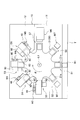
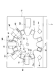
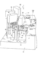
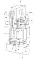
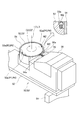
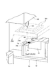
- FIG. 2 is a plan view illustrating a state in which a transport unit (rotary table) is rotated by a predetermined angle in the component assembly apparatus illustrated in FIG. 1. It is a fragmentary perspective view of the component assembly apparatus shown in FIG. It is a fragmentary perspective view of the component assembly apparatus shown in FIG. It is a perspective view which shows the components supply unit contained in the components assembly apparatus shown in FIG. It is a perspective view which shows the components supply unit contained in the components assembly apparatus shown in FIG. FIG.
- FIG. 2 is a partial perspective view showing a positional relationship between an assembly unit (assembly tool) and a component supply unit (components supplied to a component supply position) included in the component assembly apparatus shown in FIG. 1.
- FIG. 2 is a partial perspective view showing a positional relationship between an assembly unit (assembly tool) and a component supply unit (components supplied to a component supply position) included in the component assembly apparatus shown in FIG. 1.
- this component assembling apparatus is provided along a base 10, a transport unit 20 provided on the base 10, and a transport direction (circumferential direction) R of the transport unit 20 (rotary table 21 thereof).
- the base 10 is used to perform a work of transferring a plurality of work units M1, M2, M3, M4, M5, M6, M7, an assembly target W1 to the transport unit 20 and a finished product assembled with parts.
- a control unit (not shown) as a control means for performing various controls.
- the assembly target object W1 is, for example, a main body case such as a recording medium and a lid or the like superimposed on the main body case, and a component W2 to be assembled to the assembly target object W1 (FIGS. 6 and 7).
- a screw or the like for fastening the lid to the main body case is applied.
- the base 10 includes an upper surface portion 11, a step portion 12 formed lower than the upper surface portion 11, and the like.
- a station S1, a second work station S2, a third work station S3, a fourth work station S4, a fifth work station S5, a sixth work station S6, a seventh work station S7, and an eighth work station S8 are defined.
- the transport unit 20 rotates the rotary table 21 that rotates about a predetermined vertical axis L ⁇ b> 1 and the rotary table 21 intermittently at a predetermined angle (here, 22.5 degrees).
- a drive source 22 as a drive mechanism is provided.
- the turntable 21 has a plurality of (in this case, eight) holding portions 21a that are arranged at equal intervals (45 ° intervals) in the circumferential direction R and project radially, and are equidistant between the holding portions 21a. It is formed so as to define a plurality of (here, eight) openings at an interval of 45 degrees.
- the eight holding portions 21a and the eight openings are alternately arranged in the circumferential direction R at equal intervals (22.5 degrees).
- the holding portion 21a is formed in a slightly concave shape so as to position and hold the assembly target object W1.
- the drive source 22 is for intermittently driving the rotary table 21 around the vertical axis L1 at a predetermined angle (here, 22.5 degrees).
- a stepping motor or the like is applied.
- the rotary table 21 and the rotary table 21 that rotate around the vertical axis L ⁇ b> 1 having a plurality of holding portions 21 a formed to protrude radially at a predetermined interval in the circumferential direction R are intermittently provided.
- the drive source 22 that is rotationally driven, it is possible to achieve downsizing and consolidation of the apparatus as compared with the case where a conveyor or the like that is long in a predetermined direction is used as the transport unit, and also to maintain Since the space between the portions 21a is formed, the assembly units 30, 30 ', 60, 60' (assembly tools 31, 32, 33) described later can be smoothly prevented from interfering with the rotary table 21. Can be moved up and down.
- the work unit M1 is arranged in the area of the second work station S2, and reads information (model, type, etc.) of the assembly target object W1 positioned and held on the transport unit 20.
- a barcode reader or the like that reads a two-dimensional barcode or the like attached to the assembly target object W1 can be adopted.
- the work unit M2 is disposed in the area of the third work station S3 as the first assembly station, and is supported so as to be movable up and down from the upper area to the lower area of the transport unit 20.
- the assembling unit 30 disposed at a position overlapping the holding portion 21a (of the rotary table 21) in the vertical direction Z, the elevating drive unit 40 for elevating and driving the assembling unit 30, and the lower region of the transport unit 20
- the component supply unit 50 and the like are arranged to define a component supply position.
- the assembly unit 30 is provided at an upper position of the rotary table 21 (above the work position), and the assembly object W ⁇ b> 1 positioned at the work position is assembled.
- Parts supply unit corresponding from below to assembly positions (screw holes) H1, H2, H3 of the assembly object W1 positioned at the standby position and work position corresponding to the positions (screw holes) H1, H2, H3 from above 50 parts supply positions P1, P2, and P3 supported by the parts supply positions P1, P2, and P3, and the parts (screws) W2 positioned at the parts supply positions P1, P2, and P3 can be received and assembled to the assembly object W1 (screws).
- a plurality of (here, three) assembly tools 31, 32, 33 and assembly tools 31, 32, 33 that extend downward in the vertical direction Z are driven to rotate (and as required). Later causes) rotating lifting mechanism (not shown), and a guided portion 30a (see FIG. 4) which is guided by the guide rails 42 to be described later.
- the three assembling tools 31, 32, and 33 are vertically moved to the three assembling positions (screw holes) H1, H2, and H3 of the assembling object W1 positioned at the working position.
- a predetermined position part supply positions P1, P2, P3 of a part supply unit 50 described later and the vertical direction Z
- a common first circular orbit C1 centered on a predetermined vertical axis L2.
- the assembly unit 30 the assembly tools 31, 32, 33
- the component can be moved from the standby position without interfering with the holding portion 21a.
- the elevating drive unit 40 is an upright frame 41 erected on the fixed base 10 and two guides as guide members provided on the upright frame 41 and extending in the vertical direction Z to guide the guided portion 30 a of the assembly unit 30.
- a rail 42 (see FIG. 4), a lead screw 43 (see FIG. 4) arranged extending in the vertical direction Z inside the guide rail 42, screwed into the lead screw 43 and fixed to the assembly unit 30
- a nut member 44 (see FIG. 4), a drive motor 45 fixed to the upright frame 41 to rotationally drive the lead screw 43, and the like are provided.
- the elevating drive unit 40 is disposed on the stepped portion 12 of the fixed base 10 at a position where it does not interfere with the rotary table 21.
- the assembly unit 30 (the tip of the assembly tools 31, 32, 33) at the standby position above the rotary table 21 is supplied to the parts below the rotary table 21.
- the drive motor 45 is lowered to the positions P1, P2, and P3 and rotated in the other direction, it is raised from the component supply positions P1, P2, and P3 to the upper standby position. That is, when the assembling tools 31, 32, and 33 are in positions where the assembling tools 31, 32, and 33 face the opening between the holding portions 21a of the rotary table 21, the lifting / lowering driving unit 40 is positioned at the component supply positions P1, P2, and P3.
- the assembly tools 31, 32, 33 are lowered from the standby position to receive the component W2, and are raised to the standby position after receiving the part W2, and then the assembly tools 31, 32 are attached to the assembly object W1 positioned at the work position. , 33 is moved down so as to approach and the assembly unit 30 is driven up and down to assemble the component W2.
- the component supply unit 50 includes an upright frame 51 erected on the stepped portion 12 of the fixed base 10, a horizontal frame 52 fixed to the upright frame 51, and a horizontal frame 52.
- a circular rotating member 53 that is rotatably supported around the vertical axis L2 above, a drive motor (not shown) as a drive mechanism that rotationally drives the circular rotating member 53, and a horizontal frame 52 that is disposed on the outer periphery of the circular rotating member 53.
- a housing case 56 and the like for housing are provided.
- the circular rotating member 53 is disposed in a lower region than the rotary table 21, has a circular outer contour, and is coaxial with the center of the first circular track C1 and on the second circular track C2 having the same diameter.
- a plurality (three in this case) are formed so as to open upward and radially outward at the peripheral edge thereof to accommodate the component W2. It is formed so as to have a component accommodating portion 53a.
- the component introduction member 55 is formed so as to define a component introduction passage 55 a that guides the component W ⁇ b> 2 that is biased toward the component housing portion 53 a from the outside in the radial direction of the circular rotating member 53.
- the cylindrical fixing member 54 has the same height (or almost the same height) as the circular rotating member 53, and introduces components at one place in the circumferential direction and at the same height as the component accommodating portion 53 a of the circular rotating member 53.
- There is an opening 54a into which the member 55 is inserted that is, an opening that allows the component introduction passage 55a to communicate with the component housing portion 53a when the circular rotation member 53 is at a predetermined rotation angle position).
- the component W2 is supplied (pushed in) to the component accommodating portion 53a.
- the component W2 is not supplied to the component accommodating portion 53a when the component accommodating portion 53a is in a position not facing the component introduction passage 55a.
- the component W2 seated and accommodated in the component accommodating portion 53a is regulated by the inner peripheral surface (upper edge) of the cylindrical fixing member 54. That is, the cylindrical fixing member 54 allows the component W2 to be introduced into the component accommodating portion 53a when the component accommodating portion 53a faces the component introduction passage 55a as the circular rotating member 53 rotates, and the component accommodating portion.
- 53a deviates from the component introduction passage 55a the introduction of the component W2 into the component accommodating portion 53a is blocked and the dropping of the component W2 accommodated in the component accommodating portion 53a is restricted.
- the component W2 continuously supplied through the component introduction passage 55a of the component introduction member 55 has a plurality of (three) components by appropriately rotating the circular rotation member 53 with respect to the cylindrical fixing member 54.
- the components are sequentially accommodated and held in the component accommodating portion 53a, and the circular rotating member 53 stops at a predetermined rotation angle, thereby being positioned at the component supply positions P1, P2, and P3, respectively.
- the component supply unit 50 has a structure including the circular rotating member 53 having the component accommodating portion 53a, the component introducing member 55, the cylindrical fixing member 54, and the drive motor that rotationally drives the circular rotating member 53. It is possible to achieve simplification, integration, miniaturization, etc. of the structure while supplying the component W2.
- the work unit M3 is arranged in the area of the fourth work station S4 as the second assembly station, and is supported so as to be movable up and down from the upper area to the lower area of the transport unit 20 and work.
- the assembling unit 30 ′ arranged at a position overlapping the holding portion 21 a (of the rotary table 21) in the vertical direction Z, the elevating drive unit 40 for elevating and driving the assembling unit 30 ′, and the transport unit 20
- a component supply unit 50 ′ and the like arranged in the lower region and defining a component supply position are provided.
- the assembly unit 30 ′ is provided at an upper position (above the work position) of the rotary table 21 and is a set of the assembly object W ⁇ b> 1 positioned at the work position.
- the component W2 supported by the component supply positions P4, P5 and P6 of the unit 50 ′ so as to be movable up and down and positioned at the component supply positions P4, P5 and P6 is received and assembled (screwed) into the assembly target W1.
- the plurality of (in this case, three) assembly tools 31, 32, 33 and assembly tools 31, 32, 33 that extend downward in the vertical direction Z are rotationally driven (and moved up and down as necessary).
- a rotation elevating mechanism (not shown), and a guided portion 30a (see FIG. 4) guided by the guide rail 42.
- the three assembling tools 31, 32, and 33 are vertically moved to three assembling positions (screw holes) H4, H5, and H6 of the assembling object W1 positioned at the working position.
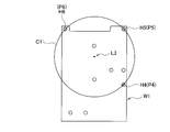
- Predetermined positions passing on a common first circular orbit C1 ′ centered on a predetermined vertical axis L3 so as to correspond in the direction Z part supply positions P4, P5, P6 of a part supply unit 50 ′ described later and the vertical direction
- Part supply positions P4, P5, P6 of a part supply unit 50 ′ described later and the vertical direction Part supply positions P4, P5, P6 of a part supply unit 50 ′ described later and the vertical direction
- the assembly unit 30 ′ (assembly tool 31, 32, 33) is located at a position facing the opening between the holding portions 21 a of the rotary table 21, the assembly unit 30 ′ can be moved from the standby position without interfering with the holding portion 21 a. It is formed so that it can be lowered to the component supply positions P4, P5, P6 of the component supply unit 50 '(its shape and arrangement position are adjusted).
- the assembly unit 30 ′ (the tips of the assembly tools 31, 32, and 33) is driven by the elevating drive unit 40 so that the standby position above the rotary table 21 and the component supply position below the rotary table 21. Can be moved up and down.
- the component supply unit 50 ′ includes an upright frame 51, a horizontal frame 52, a circular rotation member 53 ′ that is rotatably supported on the horizontal frame 52 around the vertical axis L 3, and a circular rotation member.
- a drive motor (not shown) that rotationally drives 53 ′, a cylindrical fixing member 54, a component introduction member 55, a housing case 56, and the like are provided.
- the circular rotating member 53 ′ is disposed in a lower region than the rotary table 21, has a circular outer contour, is coaxial with the center of the first circular track C1 ′, and has the same diameter as the second circular track C2 ′.
- a plurality in this case, 3) formed so as to be open upward and radially outward at the periphery thereof to accommodate the component W2.
- Component housing portion 53a The components W2 continuously supplied through the component introduction passage 55a of the component introduction member 55 are plural (three) by appropriately rotating the circular rotation member 53 ′ relative to the cylindrical fixing member 54. Are sequentially accommodated and held in the component accommodating portion 53a, and the circular rotating member 53 'stops at a predetermined rotation angle, thereby being positioned at the component supply positions P4, P5, and P6, respectively.
- the work unit M4 is disposed in the area of the fifth work station S5 as the third assembly station, and is supported so as to be movable up and down from the upper area to the lower area of the transport unit 20 and work.
- the assembling unit 60 arranged at a position overlapping the holding portion 21a (of the rotary table 21) in the vertical direction Z, the elevating drive unit 40 for elevating and driving the assembling unit 60, and the lower region of the transport unit 20
- the two component supply units 70, the assembly unit 60 (and the lifting drive unit 40), and the two component supply units 70 which are disposed in the horizontal direction and define the component supply position, are held in the horizontal direction with respect to the fixed base 10.
- a movable base 80 that moves two-dimensionally is provided.
- the assembly unit 60 is provided at an upper position (above the work position) of the rotary table 21 and a plurality of assembly objects W ⁇ b> 1 positioned at the work position.
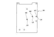
- the assembly position (screw hole) H7, H8, H9 of two assembly positions (screw holes) H7, H8 from the upper side corresponding to the assembly position and the assembly position of the assembly object W1 positioned at the work position (from above) Screw holes) H7, H8, and H9, two assembly positions (screw holes) H7 and H8 are supported in such a manner that they can be moved up and down between the component supply positions P7 and P8 of the component supply unit 70 corresponding from below.
- a plurality (in this case,) extending downward in the vertical direction Z so that the parts W2 positioned at the positions P7 and P8 are received and assembled (screwed) into the assembly positions (screw holes) H7 and H8 of the assembly object W1.
- the assembling tools 31 and 32, the assembling tools 31 and 32 are rotated and driven (and moved up and down as needed), and a guided portion 30a guided by the guide rail 42 (see FIG. 4). ).
- the two assembly tools 31 and 32 are assembly objects positioned at the working position. Positions passing through predetermined vertical axes L4 and L5 so as to correspond in the vertical direction Z to two assembly positions (screw holes) H7 and H8 among the three assembly positions (screw holes) H7, H8 and H9 of W1. Is arranged. Further, when the assembly unit 60 (the assembly tools 31 and 32) is located at a position facing the opening between the holding portions 21a of the rotary table 21, the component supply unit can be moved from the standby position without interfering with the holding portion 21a.
- the assembly unit 60 (the tips of the assembly tools 31 and 32) is driven between the standby position above the rotary table 21 and the component supply position below the rotary table 21 by driving of the elevating drive unit 40. Can be moved up and down.
- the two component supply units 70 are erected on an upright frame 71 and a horizontal frame fixed on the upright frame 71, respectively.
- a slide member 73 as a movable member supported so as to be reciprocally movable (slidable) in the horizontal direction on the frame 72 and the horizontal frame 72, and a drive mechanism (not shown) for reciprocally driving (sliding) the slide member 73;
- a component introduction passage 75a for introducing the component W2 into the slide member 73 (a component housing portion 73a described later) and a wall surface 75b adjacent to one side surface of the slide member 73 and a component introduction member 75 fixed on the horizontal frame 72 are defined.
- the parts W2 are sequentially sent out while being urged toward the slide member 73 through the part introduction passage 75a of the part introduction member 75.
- Accommodating case 76 for accommodating the W2, and a lock mechanism (not shown) or the like for locking the mounting angle in the horizontal plane relative to the horizontal frame 72 of the slide member 73 and the component introduction member 75 at an arbitrary angle.
- Each of the two slide members 73 is disposed in a lower region than the rotary table 21, and an array of a plurality of assembly positions of the assembly target object W1 (see FIG. 10A) positioned at the work position by the drive mechanism.
- One component housing portion formed so as to be slidable in a linear direction D1 in a horizontal plane parallel to the direction and opened upward and on the side facing the wall surface 75b of the component introduction member 75 so as to accommodate the component W2.
- 73a and by positioning the component accommodating portion 73a at a predetermined slide position, component supply positions P7 and P8 are defined on predetermined vertical axes L4 and L5, respectively.
- the component introduction member 75 is formed at the same height (or substantially the same height) as the slide member 73, and has a component introduction passage 75a at the same height position as the component storage portion 73a.
- the component housing portion 73a is supplied (pushed in) and seated, and the component housing portion 73a is seated.
- the component W2 is not supplied to the component housing portion 73a when the component introduction passage 75a is not located. Further, the component W2 seated and accommodated in the component accommodating portion 73a is regulated by the wall surface 75b of the component introduction member 75.
- the component introduction member 75 defines a component introduction passage 75a that guides the component W2 toward the component accommodation portion 73a, and the component introduction portion 75a faces the component introduction passage 75a as the slide member 73 moves. It is formed so as to demarcate a wall surface 75b that permits introduction of the component W2 into the housing portion 73a and restricts dropping of the component W2 housed in the component housing portion 73a when the component housing portion 73a deviates from the component introduction passage 75a. ing.
- the component W2 continuously supplied through the component introduction passage 75a of the component introduction member 75 is accommodated in the component accommodation portion 73a as the slide member 73 appropriately moves relative to the component introduction member 75.
- the slide member 73 is held and moved by a predetermined amount and stopped, so that it is positioned at the component supply positions P7 and P8, respectively.
- the component supply unit 70 has a structure including the slide member 73 having the component accommodating portion 73a, the component introduction member 75, and the drive mechanism for slidingly driving the slide member 73, a long component supply unit such as a conveyor is provided. Compared to, it is possible to achieve simplification, consolidation, miniaturization, and the like of the structure.
- the movable base 80 supports the first movable frame 81 that fixes the upright frames 41 and 71 in a standing manner, and supports the first movable frame 81 so as to reciprocate in a first direction D2 in a horizontal plane.
- the second movable frame 82, the support frame 83 that supports the second movable frame 82 so as to reciprocate in a second direction D3 perpendicular to the first direction D2 in the horizontal plane, and the first movable frame 81 are driven in the first direction D2.
- a first drive mechanism (not shown), a second drive mechanism (not shown) that drives the second movable frame 82 in the second direction D3, and a lock mechanism (not shown) that locks the movable base 80 at a predetermined position with respect to the fixed base 10. Etc.).
- the transport unit 20 is arranged on the fixed base 10
- the assembly unit 60 and the component supply unit 70 are arranged on the movable base 80 that can move two-dimensionally in the horizontal plane with respect to the fixed base 10. Therefore, the relative positional relationship between the assembly unit 60 (the assembly tools 31, 32) and the component supply unit 70 (the component supply positions P7, P8) is maintained.
- the movable base 80 is appropriately moved and positioned at a predetermined position, thereby causing a positional shift with respect to various assembly targets W1 having different assembly positions. Parts can be assembled with high accuracy without any problems.
- the work unit M5 is disposed in the area of the sixth work station S6 as the fourth assembly station, and is supported so as to be movable up and down from the upper area to the lower area of the transport unit 20 and work.
- the assembling unit 60 ′ disposed at a position overlapping the holding portion 21 a (of the rotary table 21) in the vertical direction Z, the elevating drive unit 40 for elevating and driving the assembling unit 60 ′, and the transport unit 20
- One component supply unit 70 which is disposed in the lower region and demarcating the component supply position, the assembly unit 60 ′ (and the lifting drive unit 40) and the component supply unit 70 are held together to be horizontal with respect to the fixed base 10.
- a movable base 80 or the like that moves two-dimensionally.
- the assembly unit 60 ′ is provided at an upper position (above the work position) of the rotary table 21, and an assembly position of the assembly target object W ⁇ b> 1 positioned at the work position ( Assembling positions (screw holes) H7, H8 of the assembly target object W1 positioned at the working position and the standby position corresponding to the assembling position (screw hole) H9 from among the screw holes H7, H8, H9 , H9, and receives the component W2 that is supported at the component supply position P9 and is positioned at the component supply position P9 from the lower side to the component supply position P9 of the component supply unit 70 corresponding to one assembly position (screw hole) H9.
- One assembly tool 31 that extends downward in the vertical direction Z so as to be assembled (screwed) into the assembly position (screw hole) H9 of the assembly object W1 and rotationally drive the assembly tool 31 (with Lift is allowed) rotating lifting mechanism in accordance with the requirements (not shown), and a guided portion 30a (see FIG. 4) which is guided by the guide rail 42.
- one assembling tool 31 has one assembling position (screw hole) H9 among three assembling positions (screw holes) H7, H8, H9 of the assembling object W1. Is arranged at a position passing through a predetermined vertical axis L6. Further, when the assembly unit 60 ′ (assembly tool 31) is located at a position facing the opening between the holding portions 21 a of the rotary table 21, the component supply unit 70 can be moved from the standby position without interfering with the holding portion 21 a. It is formed so that it can be lowered to the component supply position P9 (with its shape and arrangement position adjusted).
- the assembly unit 60 ′ (the tip of the assembly tool 31) is driven between the standby position above the rotary table 21 and the component supply position below the rotary table 21 by driving of the elevating drive unit 40. It can be moved up and down. Further, the component supply unit 70 supplies the component W2 to the component supply position P9 on the vertical axis L6.
- the configurations and operations of the lifting drive unit 40, the component supply unit 70, and the movable base 80 are basically the same as those included in the work unit M4, and thus description thereof is omitted.
- the work unit M6 is arranged in the area of the seventh work station S7, and the assembly object in which the component W2 is assembled and positioned and held on the transport unit 20 (the holding portion 21a thereof).
- An affixing unit that affixes a label on which predetermined information is printed to W1 and a detection unit that detects whether or not the component (screw) W2 is lifted are provided.
- the work unit M7 is arranged in the area of the eighth work station S8, and the component W2 is assembled and a label is attached to the work unit M7 so as to be positioned on the transport unit 20 (the holding part 21a).
- a bar code reader or the like can be adopted.
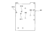
- the assembly position (screw hole) of the assembly object W1 assembled by the assembly units 60 and 60 ′ is limited to the assembly positions (screw holes) H7, H8, and H9 shown in FIG. 10A.
- the assembly positions (screw holes) H7, H8, H9 shown in FIG. 10A to FIG. 10B are shown. Assembling positions (screw holes) can be easily changed to H10, H11, and H12.
- This is performed based on the control signal of the control unit (control means).
- the work of handing the assembly object W1 with the lid placed on the main body case to the holding unit 21a of the transport unit 20 and the part W2 as described later are performed manually by the operator.
- An unloading operation for taking out the completed product after assembling from the holding portion 21a is performed.
- the delivery operation of the assembly target W1 and the removal operation of the finished product are performed each time the rotary table 21 is rotated by a predetermined angle (22.5 degrees ⁇ 2) and stopped.
- the assembly target W1 is positioned at the second work station S2, as shown in FIG.
- information (model, type, etc.) attached to the assembly object W1 is read by the work unit M1 (information reading unit), the position where the part W2 is to be attached is determined, and control is performed. Sent to the unit. This information reading operation is performed each time the turntable 21 is rotated by a predetermined angle (22.5 degrees ⁇ 2) and stopped.
- the assembly unit 30 (assembly tool 31, 32, 33) face the opening of the turntable 21, and directly face the component W2 supplied to the component supply positions P1, P2, P3 of the component supply unit 50.
- the assembling unit 30 descends from the standby position to a region below the rotary table 21, receives the component W2 at the tip, and again the assembling unit 30 (the assembling unit 31). , 32, 33) rises to a standby position above the rotary table 21 and stands by.
- the component receiving operation by the assembling unit 30 is performed every time the rotary table 21 is rotated by a predetermined angle (22.5 degrees ⁇ 2) and stopped. Further, the supply operation of the component W2 to the component supply positions P1, P2, P3 by the component supply unit 50 is performed until the assembly unit 30 receives the component W2 next time.
- the assembly target object W1 (holding portion 21a) is moved to the work position of the third work station S3. Is positioned.
- the assembling unit 30 (the assembling tools 31, 32, 33) is lowered by a predetermined amount and then driven to rotate.
- the component W2 is assembled to the assembly object W1. (Screw holes) Assemble (screw) into H1, H2, and H3.
- the assembling unit 30 (the assembling tools 31, 32, 33) rises and stops at the standby position.
- the parts assembling work by the assembling unit 30 is performed every time the rotary table 21 is rotated by a predetermined angle (22.5 degrees ⁇ 2) and stopped.
- the assembly unit 30 ′ (assembly tool 31) of the fourth work station S4. , 32, 33) face the opening of the rotary stable 21, and directly face the component W2 supplied to the component supply positions P4, P5, P6 of the component supply unit 50 ′.
- the assembling unit 30 ′ (the assembling tools 31, 32, 33) descends from the standby position to a region below the rotary table 21, and receives the part W2 at the tip thereof.
- the assembling unit 30 ′ (assembling again)
- the tools 31, 32, 33) rise to a standby position above the rotary table 21 and wait.
- the component receiving operation by the assembly unit 30 ′ is performed every time the rotary table 21 stops after rotating by a predetermined angle (22.5 degrees ⁇ 2). Further, the supply operation of the component W2 to the component supply positions P4, P5, P6 by the component supply unit 50 ′ is performed until the assembly unit 30 ′ next receives the component W2.
- the assembly target object W1 (holding portion 21a) is moved to the work position of the fourth work station S4. Is positioned.
- the assembling unit 30 ′ (the assembling tools 31, 32, 33) is lowered by a predetermined amount and then driven to rotate, and as shown in FIG. 9B, the component W2 is assembled to the assembling object W1. Assembling positions (screw holes) H4, H5, H6 are assembled (screwed).
- the assembling unit 30 ′ (the assembling tools 31, 32, 33) rises and stops at the standby position.
- the component assembling work by the assembling unit 30 ′ is performed every time the rotary table 21 rotates and stops at a predetermined angle (22.5 degrees ⁇ 2).
- the assembly unit 60 (assembly tool 31,. 32) faces the opening of the turntable 21 and directly faces the component W2 supplied to the component supply positions P7 and P8 of the component supply unit 70. Then, the assembling unit 60 (the assembling tools 31 and 32) descends from the standby position to a region below the rotary table 21 and receives the part W2 at its tip, and again, the assembling unit 60 (the assembling tools 31 and 32). ) Rises to a standby position above the rotary table 21 and stands by.
- the component receiving operation by the assembling unit 60 is performed every time the turntable 21 is rotated by a predetermined angle (22.5 degrees ⁇ 2) and stopped. Further, the supply operation of the component W2 to the component supply positions P7 and P8 by the component supply unit 70 is performed until the assembly unit 60 next receives the component W2.
- the assembly target W1 is positioned at the work position of the fifth work station S5 as shown in FIG.
- the assembling unit 60 (the assembling tools 31 and 32) is lowered by a predetermined amount and then driven to rotate.
- the component W2 is assembled to the assembly position (screw). Hole) Install (screw) into H7 and H8.
- the assembling unit 60 (the assembling tools 31, 32) rises and stops at the standby position.
- the parts assembling work by the assembling unit 60 is performed every time the rotary table 21 is rotated by a predetermined angle (22.5 degrees ⁇ 2) and stopped.
- the assembly unit 60 ′ (assembly tool 31) of the sixth work station S6. ) Faces the opening of the rotary table 21 and directly faces the component W2 supplied to the component supply position P9 of the component supply unit 70. Then, the assembling unit 60 ′ (the assembling tool 31) descends from the standby position to a region below the rotary table 21 and receives the part W2 at its tip, and the assembling unit 60 ′ (the assembling tool 31) again. Ascend to the standby position above the rotary table 21 and wait.
- the component receiving operation by the assembly unit 60 ' is performed every time the turntable 21 is rotated by a predetermined angle (22.5 degrees ⁇ 2) and stopped. Further, the supply operation of the component W2 to the component supply position P9 by the component supply unit 70 is performed until the assembly unit 60 ′ next receives the component W2.
- the assembly target W1 is positioned at the work position of the sixth work station S6 as shown in FIG.
- the assembling unit 60 ′ (the assembling tool 31) is lowered by a predetermined amount and then driven to rotate.
- the component W2 is assembled to the assembly object W1 (screw hole). ) Assemble (screw) into H9.
- the assembling unit 60 ′ (the assembling tool 31) moves up and stops at the standby position.
- the component assembling work by the assembling unit 60 ' is performed every time the rotary table 21 is rotated by a predetermined angle (22.5 degrees x 2) and stopped.
- the turntable 21 rotates clockwise by a predetermined angle (22.5 degrees ⁇ 2) and stops, the assembly target object W1 is positioned at the eighth work station S8 as shown in FIG. Then, in the eighth work station S8, the work unit M7 (information reading unit) reads the information on the label of the assembly object W1 to which the part W2 is assembled and the label is attached, and the information is sent to the control unit. It is done. This information reading operation is performed each time the turntable 21 is rotated by a predetermined angle (22.5 degrees ⁇ 2) and stopped.
- the assembly position (screw hole) for assembling the part W2 is one of the three assembly positions (screw holes) H7, H8, H9.
- the assembly positions (screw holes) H7, H8 are changed from the two assembly positions (screw holes) H7, H8 to two assembly positions (screw holes) H7, H9 or H8, H9, or the assembly in which the part W2 is assembled at the sixth work station S6.
- the movable base 80 is appropriately moved to attach the assembling unit 60, 60 'and the component supply unit 70 are positioned at predetermined positions in the horizontal plane.
- the assembling units 30, 30 ′, 60, 60 ′ are disposed so as to be movable up and down from the upper region to the lower region of the transport unit 20, and the component supply position is disposed in the lower region of the transport unit 20. Since the component supply units 50, 50 'and 70 that define P1 to P3, P4 to P6, P7 and P8, and P9 are arranged, the space in the vertical direction Z can be used effectively, the structure can be simplified, The installation area of the apparatus can be reduced (space saving) while achieving the integration of the structure and the like.
- the structure of the elevating drive unit 40 can be simplified, and errors due to movement in the horizontal direction do not occur. Therefore, there are few mechanical errors, a minute part (for example, a screw etc.) can be assembled with high accuracy, and the assembly units 30, 30 ′, 60, 60 ′ perform only the raising / lowering operation, and the component W2 Since reception and assembly are performed, useless movement can be abolished, and handling time required from reception of the part W2 to assembly can be shortened.
- a minute part for example, a screw etc.
- the movable base 80 is appropriately moved and positioned at a predetermined position, thereby causing a positional shift with respect to various assembly targets W1 having different assembly positions.
- Parts can be assembled with high accuracy without any problems. Furthermore, it is not possible to assemble at a time by assembling the part W2 in a plurality of assembling stations (the third working station S3, the fourth working station S4, the fifth working station S5, and the sixth working station S6). Such a plurality of parts W2 can be assembled smoothly and efficiently, and the operating efficiency can be improved.
- the component W2 is supplied to the component supply position corresponding to the assembly position of the assembly target object W1 positioned at the work position from below and corresponds to the work position from above.
- the assembly tools 31, 32, 33 are lowered between the standby position and the component supply position to receive the component W2 positioned at the component supply position, and then are raised again to the standby position.
- W1 is conveyed and positioned at the work position, and the assembling tools 31, 32, 33 are lowered toward the assembling position of the assembling object W1 positioned at the working position, and the part W2 is set as the assembling object W1.
- a part assembling method to be assembled is applied. According to this assembling method, it is possible to eliminate useless operations, reduce mechanical errors, assemble minute parts to an assembling object with high accuracy, and achieve a high operating rate.
- the present invention is not limited to a mode in which openings are defined between the radially projecting holding portions 21a, and other modes may be adopted.
- the conveyance unit 20 containing the rotation table 21 was employ
- adopted as a conveyance unit At least 1 holding
- a transport conveyor equipped with a drive mechanism or the like that moves the holding portion along a transport track extending in a predetermined direction and that is positioned at a work position is adopted.
- a component supply unit is disposed below the transport conveyor, and the component supply unit.
- a configuration may be adopted in which the assembly unit is placed on the upper side of the conveyor so as to be opposed to each other.
- the component supply units 50 and 50 ′ including the circular rotating members 53 and 53 ′ having the component accommodating portion 53 a are shown as the component supply units.
- the present invention is not limited to this, and components are supplied.
- a rotating member having another form may be adopted.
- the component supply unit 70 including the slide member 73 having the component accommodating portion 73a is shown as the component supply unit.
- the present invention is not limited to this, and the component supply position for supplying and positioning the component is not limited thereto. As long as it moves linearly in a predetermined direction in a horizontal plane, other forms of movable members may be employed.
- a screw is shown as the component W2
- a screw tightening tool (driver) is shown as an assembly tool of the assembly unit.
- the present invention is not limited to this, and a press-fit pin is adopted as the component W2.
- a press-fit rod may be employed as the assembly tool, or another component and another assembly tool according to the assembly of the component may be employed.
- the delivery work of the assembly target object W1 and the work of taking out the finished product in one work station S1 may be automatically performed using a conveyor, a transfer unit, and the like.
- the component supply apparatus and method of the present invention achieves the simplification of the structure, the integration of the structure, the reduction in cost, the increase in the operating rate, and the like, while reducing the installation area of the apparatus (saving space). ) And can effectively use the space in factories, etc., and can flexibly support different models, and there are few mechanical errors and it is possible to assemble minute parts with high precision. In the electrical and mechanical fields, it is also useful for assembling child parts to parent parts.
Landscapes
- Engineering & Computer Science (AREA)
- Mechanical Engineering (AREA)
- Automatic Assembly (AREA)
Abstract
本発明の部品組付け装置は、組付け対象物を保持して搬送しつつ作業位置に位置決めする搬送ユニット(20)、作業位置にある組付け対象物の組付け位置に下方から対応する部品供給位置を画定して部品を供給し位置決めする部品供給ユニット(50)、作業位置にある組付け対象物の組付け位置に上方から対応する待機位置と部品供給位置との間で昇降自在に支持されて部品を受け取って組付け対象物に組み付け組付けツール(31~33)をもつ組付けユニット(30)、組付けツールが部品供給位置にある部品を受け取り作業位置にある組付け対象物に組付けるべく組付けユニットを昇降駆動する昇降駆動ユニット(40)を含む。これによれば、構造の簡素化、構造の集約化、装置の設置面積の省スペース化等を達成できる。
Description
本発明は、電子部品あるいは機械部品等の部品を組み付ける部品組付け装置及び方法に関し、特に位置決めされた状態で間欠的に搬送される組付け対象物に部品を組み付ける部品組付け装置及び方法に関する。
従来の部品組付け装置としては、ネジを締結するワーク(組付け対象物)を保持して間欠的に搬送するインデックステーブルを含むワーク供給ユニットと、インデックステーブルから水平方向に離れた位置に配置されてネジを供給するネジ供給ユニットと、ネジ供給ユニットにより供給されたネジを吸着保持すると共にワークに対して締結動作を行うドライバユニット(組付けツール)と、ネジ供給ユニットのネジ供給位置からインデックステーブル上の組付け位置(ネジ締結位置)までネジを搬送するべくドライバユニットを昇降自在にかつ水平方向に移動自在に駆動するドライバユニット駆動手段等を備えたものが知られている(例えば、特許文献1参照)。
また、他の部品組付け装置としては、略中央に配置されると共にワーク(組付け対象物)を保持して間欠的に回転するインデックステーブルと、インデックステーブルの外周領域に配置されて昇降自在かつ回転自在でワークを把持するチャックを含むワーク供給部と、インデックステーブルの外周領域に配置されてワークのリベット孔の位置を検出する検出部と、インデックステーブルの外周領域に(水平方向に離れて)配置されてリベットを供給するリベット供給インデックス部(供給ユニット)と、リベットを保持してワークのリベット孔内に挿入するリベット挿入部と、ワークに挿入されたリベットを挟圧してかしめるプレス部と、リベットのかしめ状態を検査する検査部と、ワークをインデックステーブル上から搬出する搬出部等を備えたものが知られている(例えば、特許文献2参照)。
しかしながら、上記のような従来の部品組付け装置においては、組付けに必要な部品(ネジ、リベット)は、インデックステーブルの外周領域に配置された供給ユニットの供給位置において供給され、部品を組み付けるドライバユニット又はリベット挿入部が、供給ユニット上の供給位置とインデックステーブル上の組付け位置との間を水平移動することによって部品の供給が行われるため、ドライバユニット又はリベット挿入部を水平方向に移動させるための駆動機構が必要になり、ドライバユニット又はリベット挿入部の水平移動により組付け時間のロスを生じる。また、水平方向への移動を行うための駆動機構を必要とするため機械的な位置決め誤差を生じる虞がある。さらに、インデックステーブルの周りにおける装置の設置面積が大きくなる。
本発明は、上記従来の技術の事情に鑑みてなされたものであり、その目的とするところは、構造の簡素化、構造の集約化、低コスト化、高稼働率化等を図りつつ、装置の設置面積を小さく(省スペース化)して工場等の空間スペースを有効に活用することができ、又、異なる機種にも柔軟に対応することができ、機械的誤差が少なく微小部品を高精度に組み付けることができる部品組付け装置及び方法を提供することにある。
本発明の部品組付け装置は、組付け対象物を保持して搬送しつつ所定の作業位置に位置決めする搬送ユニットと、作業位置に位置決めされた組付け対象物の下方に配置され,組付け対象物の組付け位置に対応する部品供給位置を画定して部品を供給し位置決めする部品供給ユニットと、作業位置に位置決めされた組付け対象物の上方に配置され,上記組付け位置に対応する待機位置と部品供給位置との間で昇降自在に支持されて部品供給位置に位置決めされた部品を受け取って組付け対象物に組み付け得る組付けツールを有する組付けユニットと、組付けツールが部品供給位置に位置決めされた部品を受け取って作業位置に位置決めされた組付け対象物に組付けるべく組付けユニットを昇降駆動する昇降駆動ユニットを含む、構成となっている。
この構成によれば、例えば、作業位置(搬送ユニット)の上方の待機位置と作業位置(搬送ユニット)の下方の部品供給位置との間で組付けツールを有する組付けユニットが、昇降駆動ユニットにより昇降駆動されて、組付けツールが作業位置(搬送ユニット)の下方の(部品供給ユニットにより画定される)部品供給位置に供給された部品を受け取って搬送ユニットの上方(待機位置)まで上昇し、その後、搬送ユニットが組付け対象物を保持して搬送し部品の組付けを行う所定の作業位置に位置決めすると、組付けツールが再び下降してその部品を組付け対象物に組み付ける。
このように、作業位置(搬送ユニット)の上方に組付けツールを有する組付けユニットが配置され作業位置の上方から下方まで組付けツールが昇降可能であり、作業位置(搬送ユニット)の下方に部品供給位置を画定する部品供給ユニットが配置されるため、上下方向の空間を有効に活用することができ、構造の簡素化、構造の集約化等を達成しつつ、装置の設置面積を小さく(省スペース化)することができる。
また、組付けユニットは昇降移動のみで水平方向に移動しないため、昇降駆動ユニットの構造を簡素化でき、又、水平方向への移動に伴う誤差が発生しないため、機械的誤差が少なく、微小部品(例えば、ネジ等)を高精度に組み付けることができる。さらに、組付けユニット(組付けツール)が昇降動作のみを行って、部品の受け取り及び組付けを行うため、無駄な移動を廃止でき、部品の受け取りから組付けまでに要するハンドリング時間を短縮することができる。
この構成によれば、例えば、作業位置(搬送ユニット)の上方の待機位置と作業位置(搬送ユニット)の下方の部品供給位置との間で組付けツールを有する組付けユニットが、昇降駆動ユニットにより昇降駆動されて、組付けツールが作業位置(搬送ユニット)の下方の(部品供給ユニットにより画定される)部品供給位置に供給された部品を受け取って搬送ユニットの上方(待機位置)まで上昇し、その後、搬送ユニットが組付け対象物を保持して搬送し部品の組付けを行う所定の作業位置に位置決めすると、組付けツールが再び下降してその部品を組付け対象物に組み付ける。
このように、作業位置(搬送ユニット)の上方に組付けツールを有する組付けユニットが配置され作業位置の上方から下方まで組付けツールが昇降可能であり、作業位置(搬送ユニット)の下方に部品供給位置を画定する部品供給ユニットが配置されるため、上下方向の空間を有効に活用することができ、構造の簡素化、構造の集約化等を達成しつつ、装置の設置面積を小さく(省スペース化)することができる。
また、組付けユニットは昇降移動のみで水平方向に移動しないため、昇降駆動ユニットの構造を簡素化でき、又、水平方向への移動に伴う誤差が発生しないため、機械的誤差が少なく、微小部品(例えば、ネジ等)を高精度に組み付けることができる。さらに、組付けユニット(組付けツール)が昇降動作のみを行って、部品の受け取り及び組付けを行うため、無駄な移動を廃止でき、部品の受け取りから組付けまでに要するハンドリング時間を短縮することができる。
上記構成において、組付けツール及び部品供給位置は、作業位置に位置決めされた組付け対象物の組付け位置を通り上下方向に伸長する鉛直軸上に配置され、昇降駆動ユニットは、組付けツールを鉛直軸上に沿って昇降させるべく組付けユニットを昇降自在にガイドするガイド部材を含む、構成を採用することができる。
この構成によれば、昇降駆動ユニットにより組付けユニットを昇降させる際に、組付けユニットがガイド部材によりガイドされて、組付けツールが鉛直軸上を下降して部品供給位置に位置決めされた部品を受け取るため、部品の受け取りを高精度に行うことができる。
この構成によれば、昇降駆動ユニットにより組付けユニットを昇降させる際に、組付けユニットがガイド部材によりガイドされて、組付けツールが鉛直軸上を下降して部品供給位置に位置決めされた部品を受け取るため、部品の受け取りを高精度に行うことができる。
上記構成において、部品供給ユニットは、作業位置に位置決めされた組付け対象物の複数の組付け位置を通る共通の第1円軌道の中心と同軸上でかつ同一径の第2円軌道上において複数の部品供給位置を画定すると共に上記同軸回りに回転する回転部材を含み、この回転部材は、円形の外輪郭をなすと共にその周縁において複数の部品供給位置を画定するべく上向き及び径方向外向きに開口して部品を収容し得るように形成された複数の部品収容部を有する円形回転部材からなる、構成を採用することができる。
この構成によれば、一つの回転部材(円形回転部材)で、複数の部品供給位置を画定することができるため、部品供給ユニットを小型化することができ、それ故に、装置の簡素化、小型化等を達成することができる。
この構成によれば、一つの回転部材(円形回転部材)で、複数の部品供給位置を画定することができるため、部品供給ユニットを小型化することができ、それ故に、装置の簡素化、小型化等を達成することができる。
上記構成において、部品供給ユニットは、円形回転部材と、円形回転部材の径方向外側から部品収容部に向けて部品を導く部品導入通路を画定する部品導入部材と、部品収容部への部品の導入を許容しかつ部品収容部に収容された部品の脱落を規制する円筒状固定部材と、円形回転部材を回転駆動する駆動機構を含む、構成を採用することができる。
この構成によれば、部品導入部材の部品導入通路を通して連続的に供給される部品は、円形回転部材が円筒状固定部材に対して適宜相対的に回転することで、複数の部品収容部に順次収容されて保持され、円形回転部材が所定の回転位置に停止することにより部品供給位置にそれぞれ位置決めされる。
このように、部品供給ユニットが、部品収容部を有する円形回転部材、部品導入部材、円筒状固定部材、円形回転部材の駆動機構を含む構造をなすため、複数の部品を供給しつつも、構造の簡素化、集約化、小型化等を達成することができる。
この構成によれば、部品導入部材の部品導入通路を通して連続的に供給される部品は、円形回転部材が円筒状固定部材に対して適宜相対的に回転することで、複数の部品収容部に順次収容されて保持され、円形回転部材が所定の回転位置に停止することにより部品供給位置にそれぞれ位置決めされる。
このように、部品供給ユニットが、部品収容部を有する円形回転部材、部品導入部材、円筒状固定部材、円形回転部材の駆動機構を含む構造をなすため、複数の部品を供給しつつも、構造の簡素化、集約化、小型化等を達成することができる。
上記構成において、円筒状固定部材は、円形回転部材が所定の回転角度位置にあるとき部品導入通路を部品収容部に連通させる開口を有する、構成を採用することができる。
この構成によれば、円筒状固定部材に開口を設ける簡単な構造により、円形回転部材の回転と協働して、部品収容部への部品の導入を許容し又部品収容部への部品の導入を遮断することができる。
この構成によれば、円筒状固定部材に開口を設ける簡単な構造により、円形回転部材の回転と協働して、部品収容部への部品の導入を許容し又部品収容部への部品の導入を遮断することができる。
上記構成において、部品供給ユニットは、部品供給位置を画定すると共に,作業位置に位置決めされた組付け対象物の複数の組付け位置の配列方向に平行な所定方向に直線的に可動に支持され可動部材を含み、この可動部材は、部品供給位置を画定するべく上向き及び上記所定方向に垂直な水平方向に開口して部品を収容し得るように形成された部品収容部を有し所定方向にスライド可能なスライド部材からなる、構成を採用することができる。
この構成によれば、部品供給ユニットの簡素化、小型化を達成しつつ、可動部材(スライド部材)を適宜所定方向に移動させることで、複数の組付け位置に下方から対応する部品供給位置に部品を供給して位置決めすることができる。
この構成によれば、部品供給ユニットの簡素化、小型化を達成しつつ、可動部材(スライド部材)を適宜所定方向に移動させることで、複数の組付け位置に下方から対応する部品供給位置に部品を供給して位置決めすることができる。
上記構成において、部品供給ユニットは、スライド部材と、部品収容部に向けて部品を導く部品導入通路を画定すると共に部品収容部への部品の導入を許容しかつ部品収容部に収容された部品の脱落を規制する壁面を画定する部品導入部材と、スライド部材をスライド駆動する駆動機構を含む、構成を採用することができる。
この構成によれば、部品導入部材の部品導入通路を通して連続的に供給される部品は、スライド部材が部品導入部材の壁面に対して適宜相対的に移動することで、部品収容部に収容されて保持され、スライド部材が所定位置に停止することにより部品供給位置にそれぞれ位置決めされる。
このように、部品供給ユニットが、部品収容部を有するスライド部材、部品導入部材、スライド部材の駆動機構を含む構造をなすため、部品を連続的に供給しつつも、構造の簡素化、集約化、小型化等を達成することができる。
この構成によれば、部品導入部材の部品導入通路を通して連続的に供給される部品は、スライド部材が部品導入部材の壁面に対して適宜相対的に移動することで、部品収容部に収容されて保持され、スライド部材が所定位置に停止することにより部品供給位置にそれぞれ位置決めされる。
このように、部品供給ユニットが、部品収容部を有するスライド部材、部品導入部材、スライド部材の駆動機構を含む構造をなすため、部品を連続的に供給しつつも、構造の簡素化、集約化、小型化等を達成することができる。
上記構成において、組付けユニットは、作業位置に位置決めされた組付け対象物の複数の組付け位置にそれぞれ対応する複数の組付けツールを有する、構成を採用することができる。
この構成によれば、一つの組付けユニットが複数の組付けツール(例えば、ドライバ等のネジ締めツール、圧入ツール等)を含むため、同時に複数の部品を組み付けることができる。
この構成によれば、一つの組付けユニットが複数の組付けツール(例えば、ドライバ等のネジ締めツール、圧入ツール等)を含むため、同時に複数の部品を組み付けることができる。
上記構成において、搬送ユニットが設けられた固定ベースと、固定ベースに対して水平面内で二次元的に移動可能な可動ベースとをさらに含み、可動ベースは、組付けユニット及び部品供給ユニットを保持すると共に水平面内の第1方向に移動自在に支持された第1可動フレームと、第1可動フレームを保持して水平面内の第1方向に垂直な第2方向に移動自在に支持された第2可動フレームと、固定ベース上に設けられて第2可動フレームを移動自在に支持する支持フレームを含む、構成を採用することができる。
この構成によれば、搬送ユニットが固定ベース上に配置され、組付けユニット及び部品供給ユニットが固定ベースに対して水平面内で二次元的に移動可能な可動ベース(の第1可動フレーム)上に配置されているため、組付けユニットと部品供給ユニット(部品供給位置)との相対的な位置関係が維持される。したがって、組付け対象物が変更になった場合、可動ベースを適宜移動させて所定位置に位置決めすることで、組付け位置の異なる種々の組付け対象物に対して、位置ずれを生じることなく高精度に部品を組み付けることができる。
この構成によれば、搬送ユニットが固定ベース上に配置され、組付けユニット及び部品供給ユニットが固定ベースに対して水平面内で二次元的に移動可能な可動ベース(の第1可動フレーム)上に配置されているため、組付けユニットと部品供給ユニット(部品供給位置)との相対的な位置関係が維持される。したがって、組付け対象物が変更になった場合、可動ベースを適宜移動させて所定位置に位置決めすることで、組付け位置の異なる種々の組付け対象物に対して、位置ずれを生じることなく高精度に部品を組み付けることができる。
上記構成において、搬送ユニットは、組付け対象部を保持するべく周方向に所定の間隔をおいて放射状に突出して形成された複数の保持部を有すると共に所定の鉛直軸回りに回転する回転テーブルと、回転テーブルを間欠的に回転駆動する駆動機構とを含む、構成を採用することができる。
この構成によれば、搬送ユニットとして、複数の保持部が放射状に突出する回転テーブルを採用することで、所定方向に長尺なコンベア等を搬送ユニットとして採用する場合に比べて、装置の小型化、集約化を達成することができ、又、複数の保持部が周方向に所定間隔をおいて放射状に突出するように形成されているため、組付けツールを保持部同士の間に画定される開口に臨む位置において回転テーブルに干渉しないように円滑に昇降させることができる。
この構成によれば、搬送ユニットとして、複数の保持部が放射状に突出する回転テーブルを採用することで、所定方向に長尺なコンベア等を搬送ユニットとして採用する場合に比べて、装置の小型化、集約化を達成することができ、又、複数の保持部が周方向に所定間隔をおいて放射状に突出するように形成されているため、組付けツールを保持部同士の間に画定される開口に臨む位置において回転テーブルに干渉しないように円滑に昇降させることができる。
上記構成において、搬送ユニットは、組付け対象物を保持する保持部と、保持部を所定方向に伸長する搬送軌道に沿って移動させると共に位置決めする駆動機構とを含む、構成を採用することができる。
この構成によれば、搬送ユニットの搬送軌道に沿って複数の部品組付けステーション(組付けツールを有する組付けユニット、部品供給ユニット、昇降駆動ユニット)を容易に配置することができ、複数の部品が複数の作業ステーションに亘って組付けされる場合に適している。
この構成によれば、搬送ユニットの搬送軌道に沿って複数の部品組付けステーション(組付けツールを有する組付けユニット、部品供給ユニット、昇降駆動ユニット)を容易に配置することができ、複数の部品が複数の作業ステーションに亘って組付けされる場合に適している。
上記構成において、搬送ユニット、部品供給ユニット、組付けツール、及び昇降駆動ユニットを制御する制御手段を含み、制御手段は、部品供給位置に部品を供給して位置決めするべく部品供給ユニットを制御し、部品供給位置に位置決めされた部品を受け取った後に再び待機位置まで上昇させるべく昇降駆動ユニット及び組付けユニットを制御し、組付け対象物を搬送して作業位置に位置決めするべく搬送ユニットを制御し、作業位置に位置決めされた組付け対象物に組付けツールを接近させて部品を組み付けるべく昇降駆動ユニット及び組付けツールを制御する、構成を採用することができる。
この構成によれば、無駄な動作を無くして、機械的誤差が少なく、微小部品を組付け対象物に高精度に組み付けることができ、高稼働率化を達成することができる。
この構成によれば、無駄な動作を無くして、機械的誤差が少なく、微小部品を組付け対象物に高精度に組み付けることができ、高稼働率化を達成することができる。
また、本発明の部品組付け方法は、所定の作業位置に位置決めされた組付け対象物に対して部品を組み付ける部品組付け方法であって、作業位置に位置決めされる組付け対象物の下方に配置されて組付け位置に対応する部品供給位置に部品を供給し、作業位置に位置決めされる組付け対象物の上方に配置されて上記組付け位置に対応する待機位置と部品供給位置との間で組付けツールを下降させて部品供給位置に位置決めされた部品を受け取った後再び待機位置まで上昇させ、搬送ユニットにより組付け対象物を搬送しつつ作業位置に位置決めし、作業位置に位置決めされた組付け対象物の組付け位置に向けて組付けツールを下降させて部品を組付け対象物に組み付ける、構成となっている。
この構成によれば、無駄な動作を無くして、機械的誤差が少なく、微小部品を組付け対象物に高精度に組み付けることができ、高稼働率化を達成することができる。
この構成によれば、無駄な動作を無くして、機械的誤差が少なく、微小部品を組付け対象物に高精度に組み付けることができ、高稼働率化を達成することができる。
上記構成をなす部品組付け装置によれば、構造の簡素化、構造の集約化、低コスト化、高稼働率化等を達成しつつ、装置の設置面積を小さく(省スペース化)して工場等の空間スペースを有効に活用することができ、又、異なる機種にも柔軟に対応することができ、機械的誤差が少なく微小部品を高精度に組み付けることができる。
以下、本発明の実施形態について、添付図面を参照しつつ説明する。
この部品組付け装置は、図1及び図2に示すように、ベース10、ベース10上に設けられた搬送ユニット20、搬送ユニット20(の回転テーブル21)の搬送方向(周方向)Rに沿って配列された複数の作業ユニットM1,M2,M3,M4,M5,M6,M7、組付け対象物W1を搬送ユニット20に受け渡す作業及び部品を組み付けた完成品を取り出す作業を行うべくベース10に取り付けられた作業テーブルT、種々の制御を行う制御手段としての制御ユニット(不図示)等を備えている。
ここで、組付け対象物W1としては、例えば、記録媒体等の本体ケースと本体ケースの上に重ねられた蓋体等であり、組付け対象物W1に組み付けられる部品W2(図6及び図7参照)としては、蓋体を本体ケースに締結するネジ等が適用される。
この部品組付け装置は、図1及び図2に示すように、ベース10、ベース10上に設けられた搬送ユニット20、搬送ユニット20(の回転テーブル21)の搬送方向(周方向)Rに沿って配列された複数の作業ユニットM1,M2,M3,M4,M5,M6,M7、組付け対象物W1を搬送ユニット20に受け渡す作業及び部品を組み付けた完成品を取り出す作業を行うべくベース10に取り付けられた作業テーブルT、種々の制御を行う制御手段としての制御ユニット(不図示)等を備えている。
ここで、組付け対象物W1としては、例えば、記録媒体等の本体ケースと本体ケースの上に重ねられた蓋体等であり、組付け対象物W1に組み付けられる部品W2(図6及び図7参照)としては、蓋体を本体ケースに締結するネジ等が適用される。
ベース10は、図1ないし図4に示すように、上面部11、上面部11よりも低く形成された段差部12等を有し、図1に示すように周方向Rに順に、第1作業ステーションS1、第2作業ステーションS2、第3作業ステーションS3、第4作業ステーションS4、第5作業ステーションS5、第6作業ステーションS6、第7作業ステーションS7、第8作業ステーションS8を画定している。
搬送ユニット20は、図1ないし図4に示すように、所定の鉛直軸L1回りに回転する回転テーブル21、回転テーブル21を所定の角度(ここでは、22.5度)刻みで間欠的に回転させる駆動機構としての駆動源22等を備えている。
回転テーブル21は、周方向Rにおいて等間隔(45度の間隔)で配列されて放射状に突出する複数(ここでは、8つ)の保持部21aを有し、保持部21a同士の間に等間隔(45度の間隔)で複数(ここでは、8つ)の開口を画定するように形成されている。
すなわち、8つの保持部21aと8つの開口は、周方向Rにおいて等間隔(22.5度)で交互に配列された状態となっている。
保持部21aは、組付け対象物W1を位置決めして保持するように、例えば、若干凹状に形成されている。
駆動源22は、回転テーブル21を鉛直軸L1回りに所定の角度(ここでは、22.5度)刻みで間欠駆動するものであり、例えば、ステッピングモータ等が適用される。
このように、搬送ユニット20として、周方向Rに所定の間隔をおいて放射状に突出して形成された複数の保持部21aを有し鉛直軸L1回りに回転する回転テーブル21及び回転テーブル21を間欠的に回転駆動する駆動源22を採用することで、所定方向に長尺なコンベア等を搬送ユニットとして採用する場合に比べて、装置の小型化、集約化を達成することができ、又、保持部21a同士の間が開口して形成されているため、後述する組付けユニット30,30´,60,60´(組付けツール31,32,33)を回転テーブル21に干渉しないように円滑に昇降させることができる。
回転テーブル21は、周方向Rにおいて等間隔(45度の間隔)で配列されて放射状に突出する複数(ここでは、8つ)の保持部21aを有し、保持部21a同士の間に等間隔(45度の間隔)で複数(ここでは、8つ)の開口を画定するように形成されている。
すなわち、8つの保持部21aと8つの開口は、周方向Rにおいて等間隔(22.5度)で交互に配列された状態となっている。
保持部21aは、組付け対象物W1を位置決めして保持するように、例えば、若干凹状に形成されている。
駆動源22は、回転テーブル21を鉛直軸L1回りに所定の角度(ここでは、22.5度)刻みで間欠駆動するものであり、例えば、ステッピングモータ等が適用される。
このように、搬送ユニット20として、周方向Rに所定の間隔をおいて放射状に突出して形成された複数の保持部21aを有し鉛直軸L1回りに回転する回転テーブル21及び回転テーブル21を間欠的に回転駆動する駆動源22を採用することで、所定方向に長尺なコンベア等を搬送ユニットとして採用する場合に比べて、装置の小型化、集約化を達成することができ、又、保持部21a同士の間が開口して形成されているため、後述する組付けユニット30,30´,60,60´(組付けツール31,32,33)を回転テーブル21に干渉しないように円滑に昇降させることができる。
作業ユニットM1は、図1に示すように、第2作業ステーションS2の領域に配置されており、搬送ユニット20に位置決めして保持された組付け対象物W1の情報(型式、種類等)を読み取る情報読取ユニットである。情報読取ユニットとしては、組付け対象物W1に付された二次元のバーコード等を読み取るバーコードリーダ等を採用することができる。
作業ユニットM2は、図1に示すように、第1組付けステーションとしての第3作業ステーションS3の領域に配置されており、搬送ユニット20の上方領域から下方領域まで昇降可能に支持されると共に作業位置に位置する(回転テーブル21の)保持部21aと上下方向Zにおいてオーバーラップする位置に配置された組付けユニット30、組付けユニット30を昇降駆動する昇降駆動ユニット40、搬送ユニット20の下方領域に配置されて部品供給位置を画定する部品供給ユニット50等を備えている。
組付けユニット30は、図3、図7、図9Aに示すように、回転テーブル21の上方位置(作業位置の上方)に設けられて、作業位置に位置決めされた組付け対象物W1の組付け位置(ネジ穴)H1,H2,H3に上方から対応する待機位置と作業位置に位置決めされた組付け対象物W1の組付け位置(ネジ穴)H1,H2,H3に下方から対応する部品供給ユニット50の部品供給位置P1,P2,P3との間で昇降自在に支持されて部品供給位置P1,P2,P3に位置決めされた部品(ネジ)W2を受け取って組付け対象物W1に組み付け得る(捩じ込む)ように上下方向Zの下向きに伸長する複数(ここでは、3つ)の組付けツール31,32,33、組付けツール31,32,33をそれぞれ回転駆動する(と共に必要に応じて昇降させる)回転昇降機構(不図示)、後述するガイドレール42にガイドされる被ガイド部30a(図4参照)を備えている。
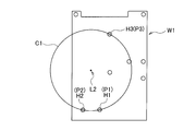
3つの組付けツール31,32,33は、図7及び図9Aに示すように、作業位置に位置決めされた組付け対象物W1の3つの組付け位置(ネジ穴)H1,H2,H3に上下方向Zにおいて対応するように、所定の鉛直軸L2を中心とする共通の第1円軌道C1上を通る所定位置(後述する部品供給ユニット50の部品供給位置P1,P2,P3と上下方向Zにおいて対応する位置)に配置されている。
また、組付けユニット30(組付けツール31,32,33)は、回転テーブル21の保持部21a同士の間の開口に臨む位置に位置するとき、保持部21aに干渉することなく待機位置から部品供給ユニット50の部品供給位置P1,P2,P3まで下降できるように(その形状及び配置位置が調整されて)形成されている。ここで、組付けツール31,32,33により部品W2を保持する機構としては、磁着、吸着、挟持等のいずれの手法であってもよい。
また、組付けユニット30(組付けツール31,32,33)は、回転テーブル21の保持部21a同士の間の開口に臨む位置に位置するとき、保持部21aに干渉することなく待機位置から部品供給ユニット50の部品供給位置P1,P2,P3まで下降できるように(その形状及び配置位置が調整されて)形成されている。ここで、組付けツール31,32,33により部品W2を保持する機構としては、磁着、吸着、挟持等のいずれの手法であってもよい。
昇降駆動ユニット40は、固定ベース10に立設された直立フレーム41、直立フレーム41に設けられて上下方向Zに伸長し組付けユニット30の被ガイド部30aをガイドするガイド部材としての2つのガイドレール42(図4参照)、ガイドレール42の内側において上下方向Zに伸長して配置されたリードスクリュー43(図4参照)、リードスクリュー43に螺合されると共に組付けユニット30に固定されたナット部材44(図4参照)、リードスクリュー43を回転駆動するべく直立フレーム41に固定された駆動モータ45等を備えている。ここで、昇降駆動ユニット40は、固定ベース10の段差部12上において、回転テーブル21と干渉しない位置に配置されている。
そして、駆動モータ45が一方向に回転すると、回転テーブル21よりも上方の待機位置にある組付けユニット30(の組付けツール31,32,33の先端)を回転テーブル21よりも下方の部品供給位置P1,P2,P3まで下降させ、駆動モータ45が他方向に回転すると、部品供給位置P1,P2,P3から上方の待機位置まで上昇させるようになっている。
すなわち、昇降駆動ユニット40は、組付けツール31,32,33が回転テーブル21の保持部21a同士の間の開口に臨む位置にあるとき、部品供給位置P1,P2,P3に位置決めされた部品W2を受け取るべく組付けツール31、32、33を待機位置から下降させると共に部品W2を受け取った後に待機位置まで上昇させ、その後、作業位置に位置決めされた組付け対象物W1に組付けツール31,32,33を接近させるように下降させて部品W2を組付けるべく、組付けユニット30を昇降駆動するようになっている。
すなわち、昇降駆動ユニット40は、組付けツール31,32,33が回転テーブル21の保持部21a同士の間の開口に臨む位置にあるとき、部品供給位置P1,P2,P3に位置決めされた部品W2を受け取るべく組付けツール31、32、33を待機位置から下降させると共に部品W2を受け取った後に待機位置まで上昇させ、その後、作業位置に位置決めされた組付け対象物W1に組付けツール31,32,33を接近させるように下降させて部品W2を組付けるべく、組付けユニット30を昇降駆動するようになっている。
部品供給ユニット50は、図3、図5、図7に示すように、固定ベース10の段差部12上に立設された直立フレーム51、直立フレーム51に固定された水平フレーム52、水平フレーム52上において鉛直軸L2回りに回転自在に支持された円形回転部材53、円形回転部材53を回転駆動する駆動機構としての駆動モータ(不図示)、円形回転部材53の外周に配置されて水平フレーム52に固定された円筒状固定部材54、部品W2を導入する部品導入部材55、部品W2を部品導入部材55(の後述する部品導入通路55a)に向けて付勢しつつ順次に送り出すべく部品W2を収容する収容ケース56等を備えている。
円形回転部材53は、回転テーブル21よりも下方領域に配置されており、円形の外輪郭をなすと共に、第1円軌道C1の中心と同軸上でかつ同一径の第2円軌道C2上において所定の回転角度で部品供給位置P1,P2,P3を画定するべく、その周縁において上向き及び径方向外向きに開口して部品W2を収容し得るように形成された複数(ここでは、3つ)の部品収容部53aを有するように形成されている。
部品導入部材55は、円形回転部材53の径方向外側から部品収容部53aに向けて付勢される部品W2を導く部品導入通路55aを画定するように形成されている。
円筒状固定部材54は、円形回転部材53と同じ高さ(又はほぼ同じ高さ)であり、周方向の一箇所でかつ円形回転部材53の部品収容部53aと同じ高さ位置に、部品導入部材55が挿入される開口54a(すなわち、円形回転部材53が所定の回転角度位置にあるとき部品導入通路55aを部品収容部53aに連通させる開口)を有する。
部品導入部材55は、円形回転部材53の径方向外側から部品収容部53aに向けて付勢される部品W2を導く部品導入通路55aを画定するように形成されている。
円筒状固定部材54は、円形回転部材53と同じ高さ(又はほぼ同じ高さ)であり、周方向の一箇所でかつ円形回転部材53の部品収容部53aと同じ高さ位置に、部品導入部材55が挿入される開口54a(すなわち、円形回転部材53が所定の回転角度位置にあるとき部品導入通路55aを部品収容部53aに連通させる開口)を有する。
そして、円筒状固定部材54に対して円形回転部材53が所定角度回転して、部品収容部53aが部品導入通路55aに臨む位置にあるとき、部品収容部53aに部品W2が供給されて(押し込まれて)着座し、部品収容部53aが部品導入通路55aに臨まない位置にあるとき、部品収容部53aに部品W2が供給されないようになっている。また、部品収容部53aに着座して収容された部品W2は、円筒状固定部材54の内周面(上縁)によりその脱落が規制されるようになっている。
すなわち、円筒状固定部材54は、円形回転部材53の回転に伴って部品収容部53aが部品導入通路55aに対向したとき部品収容部53aへの部品W2の導入を許容し、かつ、部品収容部53aが部品導入通路55aから逸脱したとき部品収容部53aへの部品W2の導入を遮断すると共に部品収容部53aに収容された部品W2の脱落を規制するようになっている。
すなわち、円筒状固定部材54は、円形回転部材53の回転に伴って部品収容部53aが部品導入通路55aに対向したとき部品収容部53aへの部品W2の導入を許容し、かつ、部品収容部53aが部品導入通路55aから逸脱したとき部品収容部53aへの部品W2の導入を遮断すると共に部品収容部53aに収容された部品W2の脱落を規制するようになっている。
また、部品導入部材55の部品導入通路55aを通して連続的に供給される部品W2は、円形回転部材53が円筒状固定部材54に対して適宜相対的に回転することで、複数(3つ)の部品収容部53aに順次収容されて保持され、円形回転部材53が所定の回転角度で停止することにより、部品供給位置P1,P2,P3にそれぞれ位置決めされるようになっている。
このように、部品供給ユニット50が、部品収容部53aを有する円形回転部材53、部品導入部材55、円筒状固定部材54、円形回転部材53を回転駆動する駆動モータを含む構造をなすため、複数の部品W2を供給しつつも、構造の簡素化、集約化、小型化等を達成することができる。
このように、部品供給ユニット50が、部品収容部53aを有する円形回転部材53、部品導入部材55、円筒状固定部材54、円形回転部材53を回転駆動する駆動モータを含む構造をなすため、複数の部品W2を供給しつつも、構造の簡素化、集約化、小型化等を達成することができる。
作業ユニットM3は、図1に示すように、第2組付けステーションとしての第4作業ステーションS4の領域に配置されており、搬送ユニット20の上方領域から下方領域まで昇降自在に支持されると共に作業位置に位置する(回転テーブル21の)保持部21aと上下方向Zにおいてオーバーラップする位置に配置された組付けユニット30´、組付けユニット30´を昇降駆動する昇降駆動ユニット40、搬送ユニット20の下方領域に配置されて部品供給位置を画定する部品供給ユニット50´等を備えている。
組付けユニット30´は、図3、図7、図9Bに示すように、回転テーブル21の上方位置(作業位置の上方)に設けられて、作業位置に位置決めされた組付け対象物W1の組付け位置(ネジ穴)H4,H5,H6に上方から対応する待機位置と作業位置に位置決めされた組付け対象物W1の組付け位置(ネジ穴)H4,H5,H6に下方から対応する部品供給ユニット50´の部品供給位置P4,P5,P6との間で昇降自在に支持されて部品供給位置P4,P5,P6に位置決めされた部品W2を受け取って組付け対象物W1に組み付ける(捩じ込む)ように上下方向Zの下向きに伸長する複数(ここでは、3つ)の組付けツール31,32,33、組付けツール31,32,33をそれぞれ回転駆動する(と共に必要に応じて昇降させる)回転昇降機構(不図示)、ガイドレール42にガイドされる被ガイド部30a(図4参照)を備えている。
3つの組付けツール31,32,33は、図7及び図9Bに示すように、作業位置に位置決めされた組付け対象物W1の3つの組付け位置(ネジ穴)H4,H5,H6に上下方向Zにおいて対応するように、所定の鉛直軸L3を中心とする共通の第1円軌道C1´上を通る所定位置(後述する部品供給ユニット50´の部品供給位置P4,P5,P6と上下方向Zにおいて対応する位置)に配置されている。
また、組付けユニット30´(組付けツール31,32,33)は、回転テーブル21の保持部21a同士の間の開口に臨む位置に位置するとき、保持部21aに干渉することなく待機位置から部品供給ユニット50´の部品供給位置P4,P5,P6まで下降できるように(その形状及び配置位置が調整されて)形成されている。
そして、組付けユニット30´(の組付けツール31,32,33の先端)は、昇降駆動ユニット40の駆動により、回転テーブル21よりも上方の待機位置と回転テーブル21よりも下方の部品供給位置との間を昇降させられるようになっている。
また、組付けユニット30´(組付けツール31,32,33)は、回転テーブル21の保持部21a同士の間の開口に臨む位置に位置するとき、保持部21aに干渉することなく待機位置から部品供給ユニット50´の部品供給位置P4,P5,P6まで下降できるように(その形状及び配置位置が調整されて)形成されている。
そして、組付けユニット30´(の組付けツール31,32,33の先端)は、昇降駆動ユニット40の駆動により、回転テーブル21よりも上方の待機位置と回転テーブル21よりも下方の部品供給位置との間を昇降させられるようになっている。
部品供給ユニット50´は、前述の部品供給ユニット50と同様に、直立フレーム51、水平フレーム52、水平フレーム52上において鉛直軸L3回りに回転自在に支持された円形回転部材53´、円形回転部材53´を回転駆動する駆動モータ(不図示)、円筒状固定部材54、部品導入部材55、収容ケース56等を備えている。
円形回転部材53´は、回転テーブル21よりも下方領域に配置されており、円形の外輪郭をなすと共に、第1円軌道C1´の中心と同軸上でかつ同一径の第2円軌道C2´上において所定の回転角度で部品供給位置P4,P5,P6を画定するべく、その周縁において上向き及び径方向外向きに開口して部品W2を収容し得るように形成された複数(ここでは、3つ)の部品収容部53aを有するように形成されている。
そして、部品導入部材55の部品導入通路55aを通して連続的に供給される部品W2は、円形回転部材53´が円筒状固定部材54に対して適宜相対的に回転することで、複数(3つ)の部品収容部53aに順次収容されて保持され、円形回転部材53´が所定の回転角度で停止することにより、部品供給位置P4,P5,P6にそれぞれ位置決めされるようになっている。
円形回転部材53´は、回転テーブル21よりも下方領域に配置されており、円形の外輪郭をなすと共に、第1円軌道C1´の中心と同軸上でかつ同一径の第2円軌道C2´上において所定の回転角度で部品供給位置P4,P5,P6を画定するべく、その周縁において上向き及び径方向外向きに開口して部品W2を収容し得るように形成された複数(ここでは、3つ)の部品収容部53aを有するように形成されている。
そして、部品導入部材55の部品導入通路55aを通して連続的に供給される部品W2は、円形回転部材53´が円筒状固定部材54に対して適宜相対的に回転することで、複数(3つ)の部品収容部53aに順次収容されて保持され、円形回転部材53´が所定の回転角度で停止することにより、部品供給位置P4,P5,P6にそれぞれ位置決めされるようになっている。
作業ユニットM4は、図1に示すように、第3組付けステーションとしての第5作業ステーションS5の領域に配置されており、搬送ユニット20の上方領域から下方領域まで昇降自在に支持されると共に作業位置に位置する(回転テーブル21の)保持部21aと上下方向Zにおいてオーバーラップする位置に配置された組付けユニット60、組付けユニット60を昇降駆動する昇降駆動ユニット40、搬送ユニット20の下方領域に配置されて部品供給位置を画定する2つの部品供給ユニット70、組付けユニット60(及び昇降駆動ユニット40)と2つの部品供給ユニット70を一緒に保持して固定ベース10に対して水平方向に二次元的に移動する可動ベース80等を備えている。
組付けユニット60は、図4、図8、図10Aに示すように、回転テーブル21の上方位置(作業位置の上方)に設けられて、作業位置に位置決めされた組付け対象物W1の複数の組付け位置(ネジ穴)H7,H8,H9のうち2つの組付け位置(ネジ穴)H7,H8に上方から対応する待機位置と作業位置に位置決めされた組付け対象物W1の組付け位置(ネジ穴)H7,H8,H9のうち2つの組付け位置(ネジ穴)H7,H8に下方から対応する部品供給ユニット70の部品供給位置P7,P8との間で昇降自在に支持されて部品供給位置P7,P8に位置決めされた部品W2を受け取って組付け対象物W1の組付け位置(ネジ穴)H7,H8に組み付ける(捩じ込む)ように上下方向Zの下向きに伸長する複数(ここでは、2つ)の組付けツール31,32、組付けツール31,32をそれぞれ回転駆動する(と共に必要に応じて昇降させる)回転昇降機構(不図示)、ガイドレール42にガイドされる被ガイド部30a(図4参照)を備えている。
2つの組付けツール31,32は、図8(ここでは、一つの組付けツール32と一つの部品供給ユニット70を省略)及び図10Aに示すように、作業位置に位置決めされた組付け対象物W1の3つの組付け位置(ネジ穴)H7,H8,H9のうち2つの組付け位置(ネジ穴)H7,H8に上下方向Zにおいて対応するように、所定の鉛直軸L4,L5を通る位置に配置されている。
また、組付けユニット60(組付けツール31,32)は、回転テーブル21の保持部21a同士の間の開口に臨む位置に位置するとき、保持部21aに干渉することなく待機位置から部品供給ユニット70の部品供給位置P7,P8まで下降できるように(その形状及び配置位置が調整されて)形成されている。
そして、組付けユニット60(の組付けツール31,32の先端)は、昇降駆動ユニット40の駆動により、回転テーブル21よりも上方の待機位置と回転テーブル21よりも下方の部品供給位置との間を昇降させられるようになっている。
また、組付けユニット60(組付けツール31,32)は、回転テーブル21の保持部21a同士の間の開口に臨む位置に位置するとき、保持部21aに干渉することなく待機位置から部品供給ユニット70の部品供給位置P7,P8まで下降できるように(その形状及び配置位置が調整されて)形成されている。
そして、組付けユニット60(の組付けツール31,32の先端)は、昇降駆動ユニット40の駆動により、回転テーブル21よりも上方の待機位置と回転テーブル21よりも下方の部品供給位置との間を昇降させられるようになっている。
2つの部品供給ユニット70は、図4、図6、図8、図9A及び図9Bに示すように、それぞれ、可動ベース80上に立設された直立フレーム71、直立フレーム71に固定された水平フレーム72、水平フレーム72上において各々水平方向に往復動自在に(スライド可能に)支持された可動部材としてのスライド部材73、スライド部材73を往復駆動(スライド駆動)する駆動機構(不図示)、スライド部材73(の後述する部品収容部73a)に部品W2を導入する部品導入通路75a及びスライド部材73の一側面に隣接する壁面75bを画定すると共に水平フレーム72上に固定された部品導入部材75、部品W2を部品導入部材75の部品導入通路75aを通してスライド部材73に向けて付勢しつつ順次に送り出すべく部品W2を収容する収容ケース76、スライド部材73及び部品導入部材75の水平フレーム72に対する水平面内での取付け角度を任意の角度でロックするロック機構(不図示)等を備えている。
2つのスライド部材73は、それぞれ、回転テーブル21よりも下方領域に配置されており、駆動機構により、作業位置に位置決めされた組付け対象物W1(図10A参照)の複数の組付け位置の配列方向と平行な水平面内の直線方向D1にスライド可能に形成され、上向き及び部品導入部材75の壁面75bと対面する側に開口して部品W2を収容し得るように形成された1つの部品収容部73aを有し、所定のスライド位置に部品収容部73aを位置付けることで、それぞれ、所定の鉛直軸L4,L5上に部品供給位置P7,P8を画定するようになっている。
部品導入部材75は、スライド部材73と同じ高さ(又はほぼ同じ高さ)に形成され、部品収容部73aと同じ高さ位置に部品導入通路75aを有する。そして、スライド部材73がスライドして、部品収容部73aが部品導入通路75aに臨む位置にあるとき、部品収容部73aに部品W2が供給されて(押し込まれて)着座し、部品収容部73aが部品導入通路75aに臨まない位置にあるとき、部品収容部73aに部品W2が供給されないようになっている。また、部品収容部73aに着座して収容された部品W2は、部品導入部材75の壁面75bによりその脱落が規制されるようになっている。
部品導入部材75は、スライド部材73と同じ高さ(又はほぼ同じ高さ)に形成され、部品収容部73aと同じ高さ位置に部品導入通路75aを有する。そして、スライド部材73がスライドして、部品収容部73aが部品導入通路75aに臨む位置にあるとき、部品収容部73aに部品W2が供給されて(押し込まれて)着座し、部品収容部73aが部品導入通路75aに臨まない位置にあるとき、部品収容部73aに部品W2が供給されないようになっている。また、部品収容部73aに着座して収容された部品W2は、部品導入部材75の壁面75bによりその脱落が規制されるようになっている。
すなわち、部品導入部材75は、部品収容部73aに向けて部品W2を導く部品導入通路75aを画定すると共に、スライド部材73の移動に伴って部品収容部73aが部品導入通路75aに対向したとき部品収容部73aへの部品W2の導入を許容しかつ部品収容部73aが部品導入通路75aから逸脱したとき部品収容部73aに収容された部品W2の脱落を規制する壁面75bを画定するように形成されている。
そして、部品導入部材75の部品導入通路75aを通して連続的に供給される部品W2は、スライド部材73が部品導入部材75に対して適宜相対的に移動することで、部品収容部73aに収容されて保持され、スライド部材73が所定量移動して停止することにより、それぞれ部品供給位置P7,P8に位置決めされるようになっている。
このように、部品供給ユニット70が、部品収容部73aを有するスライド部材73、部品導入部材75、スライド部材73をスライド駆動する駆動機構を含む構造をなすため、コンベア等の長尺な部品供給ユニットに比べて、構造の簡素化、集約化、小型化等を達成することができる。
そして、部品導入部材75の部品導入通路75aを通して連続的に供給される部品W2は、スライド部材73が部品導入部材75に対して適宜相対的に移動することで、部品収容部73aに収容されて保持され、スライド部材73が所定量移動して停止することにより、それぞれ部品供給位置P7,P8に位置決めされるようになっている。
このように、部品供給ユニット70が、部品収容部73aを有するスライド部材73、部品導入部材75、スライド部材73をスライド駆動する駆動機構を含む構造をなすため、コンベア等の長尺な部品供給ユニットに比べて、構造の簡素化、集約化、小型化等を達成することができる。
可動ベース80は、図4に示すように、直立フレーム41,71を立設させて固定する第1可動フレーム81、第1可動フレーム81を水平面内の第1方向D2に往復動自在に支持する第2可動フレーム82、第2可動フレーム82を水平面内の第1方向D2に垂直な第2方向D3に往復動自在に支持する支持フレーム83、第1可動フレーム81を第1方向D2に駆動する第1駆動機構(不図示)、第2可動フレーム82を第2方向D3に駆動する第2駆動機構(不図示)、可動ベース80を固定ベース10に対して所定位置にロックするロック機構(不図示)等を備えている。
このように、搬送ユニット20が固定ベース10上に配置され、組付けユニット60及び部品供給ユニット70が固定ベース10に対して水平面内で二次元的に移動可能な可動ベース80上に配置されているため、組付けユニット60(の組付けツール31,32)と部品供給ユニット70(の部品供給位置P7,P8)との相対的な位置関係が維持される。したがって、組付け対象物W1が変更になった場合、可動ベース80を適宜移動させて所定位置に位置決めすることで、組付け位置の異なる種々の組付け対象物W1に対して、位置ずれを生じることなく高精度に部品を組み付けることができる。
このように、搬送ユニット20が固定ベース10上に配置され、組付けユニット60及び部品供給ユニット70が固定ベース10に対して水平面内で二次元的に移動可能な可動ベース80上に配置されているため、組付けユニット60(の組付けツール31,32)と部品供給ユニット70(の部品供給位置P7,P8)との相対的な位置関係が維持される。したがって、組付け対象物W1が変更になった場合、可動ベース80を適宜移動させて所定位置に位置決めすることで、組付け位置の異なる種々の組付け対象物W1に対して、位置ずれを生じることなく高精度に部品を組み付けることができる。
作業ユニットM5は、図1に示すように、第4組付けステーションとしての第6作業ステーションS6の領域に配置されており、搬送ユニット20の上方領域から下方領域まで昇降自在に支持されると共に作業位置に位置する(回転テーブル21の)保持部21aと上下方向Zにおいてオーバーラップする位置に配置された組付けユニット60´、組付けユニット60´を昇降駆動する昇降駆動ユニット40、搬送ユニット20の下方領域に配置されて部品供給位置を画定する1つの部品供給ユニット70、組付けユニット60´(及び昇降駆動ユニット40)と部品供給ユニット70を一緒に保持して固定ベース10に対して水平方向に二次元的に移動する可動ベース80等を備えている。
組付けユニット60´は、図8、図10Aに示すように、回転テーブル21の上方位置(作業位置の上方)に設けられて、作業位置に位置決めされた組付け対象物W1の組付け位置(ネジ穴)H7,H8,H9のうち1つの組付け位置(ネジ穴)H9に上方から対応する待機位置と作業位置に位置決めされた組付け対象物W1の組付け位置(ネジ穴)H7,H8,H9のうち1つの組付け位置(ネジ穴)H9に下方から対応する部品供給ユニット70の部品供給位置P9との間で昇降自在に支持されて部品供給位置P9に位置決めされた部品W2を受け取って組付け対象物W1の組付け位置(ネジ穴)H9に組み付ける(捩じ込む)ように上下方向Zの下向きに伸長する1つの組付けツール31、組付けツール31を回転駆動する(と共に必要に応じて昇降させる)回転昇降機構(不図示)、ガイドレール42にガイドされる被ガイド部30a(図4参照)を備えている。
1つの組付けツール31は、図8及び図10Aに示すように、組付け対象物W1の3つの組付け位置(ネジ穴)H7,H8,H9のうち1つの組付け位置(ネジ穴)H9に対応するように、所定の鉛直軸L6を通る位置に配置されている。
また、組付けユニット60´(組付けツール31)は、回転テーブル21の保持部21a同士の間の開口に臨む位置に位置するとき、保持部21aに干渉することなく待機位置から部品供給ユニット70の部品供給位置P9まで下降できるように(その形状及び配置位置が調整されて)形成されている。
そして、組付けユニット60´(の組付けツール31の先端)は、昇降駆動ユニット40の駆動により、回転テーブル21よりも上方の待機位置と回転テーブル21よりも下方の部品供給位置との間を昇降させられるようになっている。
また、部品供給ユニット70は、部品W2を鉛直軸L6上の部品供給位置P9に供給するようになっている。
尚、作業ユニットM5において、昇降駆動ユニット40、部品供給ユニット70、可動ベース80の構成及び動作については、作業ユニットM4に含まれるものと基本的に同一であるため説明を省略する。
また、組付けユニット60´(組付けツール31)は、回転テーブル21の保持部21a同士の間の開口に臨む位置に位置するとき、保持部21aに干渉することなく待機位置から部品供給ユニット70の部品供給位置P9まで下降できるように(その形状及び配置位置が調整されて)形成されている。
そして、組付けユニット60´(の組付けツール31の先端)は、昇降駆動ユニット40の駆動により、回転テーブル21よりも上方の待機位置と回転テーブル21よりも下方の部品供給位置との間を昇降させられるようになっている。
また、部品供給ユニット70は、部品W2を鉛直軸L6上の部品供給位置P9に供給するようになっている。
尚、作業ユニットM5において、昇降駆動ユニット40、部品供給ユニット70、可動ベース80の構成及び動作については、作業ユニットM4に含まれるものと基本的に同一であるため説明を省略する。
作業ユニットM6は、図1に示すように、第7作業ステーションS7の領域に配置されており、部品W2が組み付けられて搬送ユニット20(の保持部21a)上に位置決め保持された組付け対象物W1に対して、所定の情報を印刷したラベルを貼付する貼付ユニットと、部品(ネジ)W2の浮き上がりの有無を検知する検知ユニットを備えている。
作業ユニットM7は、図1に示すように、第8作業ステーションS8の領域に配置されており、部品W2が組み付けられかつラベルが貼付されて搬送ユニット20(の保持部21a)上に位置決めして保持された組付け対象物W1のラベルの情報を読み取る情報読取ユニットである。情報読取ユニットとしては、ラベルに二次元のバーコード等が記載されている場合、バーコードリーダ等を採用することができる。
上記実施形態において、組付けユニット60,60´により組み付けられる組付け対象物W1の組付け位置(ネジ穴)は、図10Aに示した組付け位置(ネジ穴)H7,H8,H9に限定されるものではなく、例えば、スライド部材73及び部品導入部材75のロック機構及び可動ベース80を適宜調整することで、図10Aに示す組付け位置(ネジ穴)H7,H8,H9から図10Bに示す組付け位置(ネジ穴)H10,H11,H12に容易に変更することができる。
次に、上記部品組付け装置の動作について説明する。
ここで、搬送ユニット20、部品供給ユニット50,50´,70、組付けツール31,32,33(組付けユニット30,30´,60,60´)、昇降駆動ユニット40等の駆動制御は、制御ユニット(制御手段)の制御信号に基づいて行われる。
先ず、第1作業ステーションS1において、作業者の手作業により、本体ケースに蓋体を重ねた組付け対象物W1を搬送ユニット20の保持部21aに受け渡す作業と、後述するように部品W2の組付けが完了した完成品を保持部21aから取り出す取り出し作業とが行われる。
この組付け対象物W1の受渡し作業と完成品の取り出し作業とは、回転テーブル21が所定角度(22.5度×2)回転して停止する度に行われる。
ここで、搬送ユニット20、部品供給ユニット50,50´,70、組付けツール31,32,33(組付けユニット30,30´,60,60´)、昇降駆動ユニット40等の駆動制御は、制御ユニット(制御手段)の制御信号に基づいて行われる。
先ず、第1作業ステーションS1において、作業者の手作業により、本体ケースに蓋体を重ねた組付け対象物W1を搬送ユニット20の保持部21aに受け渡す作業と、後述するように部品W2の組付けが完了した完成品を保持部21aから取り出す取り出し作業とが行われる。
この組付け対象物W1の受渡し作業と完成品の取り出し作業とは、回転テーブル21が所定角度(22.5度×2)回転して停止する度に行われる。
続いて、回転テーブル21が所定角度(22.5度×2)時計回りに回転して停止すると、図1に示すように、組付け対象物W1が第2作業ステーションS2に位置決めされる。そして、第2作業ステーションS2において、作業ユニットM1(情報読取ユニット)により、組付け対象物W1に付された情報(型式、種類等)が読み取られ、部品W2を取り付けるべき位置が決定され、制御ユニットに送られる。
この情報読取作業は、回転テーブル21が所定角度(22.5度×2)回転して停止する度に行われる。
この情報読取作業は、回転テーブル21が所定角度(22.5度×2)回転して停止する度に行われる。
続いて、回転テーブル21が所定角度(22.5度)時計回りに回転して停止すると、図2及び図7に示すように、第3作業ステーションS3の組付けユニット30(組付けツール31,32,33)が回転テーブル21の開口に臨み、部品供給ユニット50の部品供給位置P1,P2,P3に供給された部品W2と直接対向する。そして、組付けユニット30(組付けユニット31,32,33)が待機位置から回転テーブル21よりも下方領域まで下降してその先端で部品W2を受け取り、再び、組付けユニット30(組付けユニット31,32,33)が回転テーブル21よりも上方の待機位置まで上昇して待機する。
この組付けユニット30による部品受け取り作業は、回転テーブル21が所定角度(22.5度×2)回転して停止する度に行われる。また、部品供給ユニット50により部品W2の部品供給位置P1,P2,P3への供給動作は、組付けユニット30が次に部品W2を受け取るまでの間に行われる。
この組付けユニット30による部品受け取り作業は、回転テーブル21が所定角度(22.5度×2)回転して停止する度に行われる。また、部品供給ユニット50により部品W2の部品供給位置P1,P2,P3への供給動作は、組付けユニット30が次に部品W2を受け取るまでの間に行われる。
続いて、回転テーブル21が所定角度(22.5度)時計回りに回転して停止すると、図1に示すように、組付け対象物W1(保持部21a)が第3作業ステーションS3の作業位置に位置決めされる。
続いて、組付けユニット30(組付けツール31,32,33)が、所定量だけ下降した後各々回転駆動されて、図9Aに示すように、部品W2を組付け対象物W1の組付け位置(ネジ穴)H1,H2,H3に組み付ける(捩じ込む)。その後、組付けユニット30(組付けツール31,32,33)は、上昇して待機位置に停止する。
この組付けユニット30による部品組付け作業は、回転テーブル21が所定角度(22.5度×2)回転して停止する度に行われる。
続いて、組付けユニット30(組付けツール31,32,33)が、所定量だけ下降した後各々回転駆動されて、図9Aに示すように、部品W2を組付け対象物W1の組付け位置(ネジ穴)H1,H2,H3に組み付ける(捩じ込む)。その後、組付けユニット30(組付けツール31,32,33)は、上昇して待機位置に停止する。
この組付けユニット30による部品組付け作業は、回転テーブル21が所定角度(22.5度×2)回転して停止する度に行われる。
続いて、回転テーブル21が所定角度(22.5度)時計回りに回転して停止すると、図2及び図7に示すように、第4作業ステーションS4の組付けユニット30´(組付けツール31,32,33)が回転ステーブル21の開口に臨み、部品供給ユニット50´の部品供給位置P4,P5,P6に供給された部品W2と直接対向する。そして、組付けユニット30´(組付けツール31,32,33)が待機位置から回転テーブル21よりも下方領域まで下降してその先端で部品W2を受け取り、再び、組付けユニット30´(組付けツール31,32,33)が回転テーブル21よりも上方の待機位置まで上昇して待機する。
この組付けユニット30´による部品受け取り作業は、回転テーブル21が所定角度(22.5度×2)回転して停止する度に行われる。また、部品供給ユニット50´により部品W2の部品供給位置P4,P5,P6への供給動作は、組付けユニット30´が次に部品W2を受け取るまでの間に行われる。
この組付けユニット30´による部品受け取り作業は、回転テーブル21が所定角度(22.5度×2)回転して停止する度に行われる。また、部品供給ユニット50´により部品W2の部品供給位置P4,P5,P6への供給動作は、組付けユニット30´が次に部品W2を受け取るまでの間に行われる。
続いて、回転テーブル21が所定角度(22.5度)時計回りに回転して停止すると、図1に示すように、組付け対象物W1(保持部21a)が第4作業ステーションS4の作業位置に位置決めされる。
続いて、組付けユニット30´(組付けツール31,32,33)が、所定量だけ下降した後各々回転駆動されて、図9(b)に示すように、部品W2を組付け対象物W1の組付け位置(ネジ穴)H4,H5,H6に組み付ける(捩じ込む)。その後、組付けユニット30´(組付けツール31,32,33)は、上昇して待機位置に停止する。
この組付けユニット30´による部品組付け作業は、回転テーブル21が所定角度(22.5度×2)回転して停止する度に行われる。
続いて、組付けユニット30´(組付けツール31,32,33)が、所定量だけ下降した後各々回転駆動されて、図9(b)に示すように、部品W2を組付け対象物W1の組付け位置(ネジ穴)H4,H5,H6に組み付ける(捩じ込む)。その後、組付けユニット30´(組付けツール31,32,33)は、上昇して待機位置に停止する。
この組付けユニット30´による部品組付け作業は、回転テーブル21が所定角度(22.5度×2)回転して停止する度に行われる。
続いて、回転テーブル21が所定角度(22.5度)時計回りに回転して停止すると、図2及び図8に示すように、第5作業ステーションS5の組付けユニット60(組付けツール31,32)が回転テーブル21の開口に臨み、部品供給ユニット70の部品供給位置P7,P8に供給された部品W2と直接対向する。そして、組付けユニット60(組付けツール31,32)が待機位置から回転テーブル21よりも下方領域まで下降してその先端で部品W2を受け取り、再び、組付けユニット60(組付けツール31,32)が回転テーブル21よりも上方の待機位置まで上昇して待機する。
この組付けユニット60による部品受け取り作業は、回転テーブル21が所定角度(22.5度×2)回転して停止する度に行われる。また、部品供給ユニット70により部品W2の部品供給位置P7,P8への供給動作は、組付けユニット60が次に部品W2を受け取るまでの間に行われる。
この組付けユニット60による部品受け取り作業は、回転テーブル21が所定角度(22.5度×2)回転して停止する度に行われる。また、部品供給ユニット70により部品W2の部品供給位置P7,P8への供給動作は、組付けユニット60が次に部品W2を受け取るまでの間に行われる。
続いて、回転テーブル21が所定角度(22.5度)時計回りに回転して停止すると、図1に示すように、組付け対象物W1が第5作業ステーションS5の作業位置に位置決めされる。
続いて、組付けユニット60(組付けツール31,32)が、所定量だけ下降した後各々回転駆動されて、図10Aに示すように、部品W2を組付け対象物W1の組付け位置(ネジ穴)H7,H8に組み付ける(捩じ込む)。その後、組付けユニット60(組付けツール31,32)は、上昇して待機位置に停止する。
この組付けユニット60による部品組付け作業は、回転テーブル21が所定角度(22.5度×2)回転して停止する度に行われる。
続いて、組付けユニット60(組付けツール31,32)が、所定量だけ下降した後各々回転駆動されて、図10Aに示すように、部品W2を組付け対象物W1の組付け位置(ネジ穴)H7,H8に組み付ける(捩じ込む)。その後、組付けユニット60(組付けツール31,32)は、上昇して待機位置に停止する。
この組付けユニット60による部品組付け作業は、回転テーブル21が所定角度(22.5度×2)回転して停止する度に行われる。
続いて、回転テーブル21が所定角度(22.5度)時計回りに回転して停止すると、図2及び図8に示すように、第6作業ステーションS6の組付けユニット60´(組付けツール31)が回転テーブル21の開口に臨み、部品供給ユニット70の部品供給位置P9に供給された部品W2と直接対向する。そして、組付けユニット60´(組付けツール31)が待機位置から回転テーブル21よりも下方領域まで下降してその先端で部品W2を受け取り、再び、組付けユニット60´(組付けツール31)が回転テーブル21よりも上方の待機位置まで上昇して待機する。
この組付けユニット60´による部品受け取り作業は、回転テーブル21が所定角度(22.5度×2)回転して停止する度に行われる。また、部品供給ユニット70により部品W2の部品供給位置P9への供給動作は、組付けユニット60´が次に部品W2を受け取るまでの間に行われる。
この組付けユニット60´による部品受け取り作業は、回転テーブル21が所定角度(22.5度×2)回転して停止する度に行われる。また、部品供給ユニット70により部品W2の部品供給位置P9への供給動作は、組付けユニット60´が次に部品W2を受け取るまでの間に行われる。
続いて、回転テーブル21が所定角度(22.5度)時計回りに回転して停止すると、図1に示すように、組付け対象物W1が第6作業ステーションS6の作業位置に位置決めされる。
続いて、組付けユニット60´(組付けツール31)が、所定量だけ下降した後各々回転駆動されて、図10Aに示すように、部品W2を組付け対象物W1の組付け位置(ネジ穴)H9に組み付ける(捩じ込む)。その後、組付けユニット60´(組付けツール31)は、上昇して待機位置に停止する。
この組付けユニット60´による部品組付け作業は、回転テーブル21が所定角度(22.5度×2)回転して停止する度に行われる。
続いて、組付けユニット60´(組付けツール31)が、所定量だけ下降した後各々回転駆動されて、図10Aに示すように、部品W2を組付け対象物W1の組付け位置(ネジ穴)H9に組み付ける(捩じ込む)。その後、組付けユニット60´(組付けツール31)は、上昇して待機位置に停止する。
この組付けユニット60´による部品組付け作業は、回転テーブル21が所定角度(22.5度×2)回転して停止する度に行われる。
続いて、回転テーブル21が所定角度(22.5度×2)時計回りに回転して停止すると、図1に示すように、組付け対象物W1が第7作業ステーションS7に位置決めされる。そして、第7作業ステーションS7において、作業ユニットM6(貼付ユニット、検知ユニット)により、部品W2が組み付けられた組付け対象物W1に対して、所定の情報を印刷したラベルが貼付され、又、部品(ネジ)W2の浮き上がりの有無が検知される。尚、部品W2の浮き上がりが有った場合は、作業者にそのことを知らせる報知信号が発せられ又その情報が制御ユニットに送られる。
この貼付作業及び検知作業は、回転テーブル21が所定角度(22.5度×2)回転して停止する度に行われる。
この貼付作業及び検知作業は、回転テーブル21が所定角度(22.5度×2)回転して停止する度に行われる。
続いて、回転テーブル21が所定角度(22.5度×2)時計回りに回転して停止すると、図1に示すように、組付け対象物W1が第8作業ステーションS8に位置決めされる。そして、第8作業ステーションS8において、作業ユニットM7(情報読取ユニット)により、部品W2が組み付けられかつラベルが貼付された組付け対象物W1のラベルの情報が読み取られ、その情報が制御ユニットに送られる。
この情報読取作業は、回転テーブル21が所定角度(22.5度×2)回転して停止する度に行われる。
この情報読取作業は、回転テーブル21が所定角度(22.5度×2)回転して停止する度に行われる。
続いて、回転テーブル21が所定角度(22.5度×2)時計回りに回転して停止すると、図1に示すように、組付け対象物W1が第1作業ステーションS1に戻り、部品W2の組付けが完成した完成品が、作業者によって保持部21aから作業テーブルT上に取り出される。
この取り出し作業は、回転テーブル21が所定角度(22.5度×2)回転して停止する度に行われる。
以上のように、回転テーブル21が一回転すると、それ以後においては、同様の作業が、回転テーブル21の間欠的な回転に伴って連続的に行われる。
この取り出し作業は、回転テーブル21が所定角度(22.5度×2)回転して停止する度に行われる。
以上のように、回転テーブル21が一回転すると、それ以後においては、同様の作業が、回転テーブル21の間欠的な回転に伴って連続的に行われる。
ここで、組付け対象物W1の種類が変更されて、第5作業ステーションS5において、部品W2を組み付ける組付け位置(ネジ穴)が3つの組付け位置(ネジ穴)H7,H8,H9のうちの2つの組付け位置(ネジ穴)H7,H8から2つの組付け位置(ネジ穴)H7,H9又はH8,H9に変更された場合、又は、第6作業ステーションS6において、部品W2を組み付ける組付け位置(ネジ穴)が1つの組付け位置(ネジ穴)H9から1つの組付け位置(ネジ穴)H7又はH8に変更された場合、可動ベース80を適宜移動させて、組付けユニット60,60´及び部品供給ユニット70が水平面内の所定位置に位置決めされる。
以上述べた部品組付け装置によれば、搬送ユニット20の上方領域から下方領域まで昇降自在に組付けユニット30,30´,60,60´が配置され、搬送ユニット20の下方領域に部品供給位置P1~P3、P4~P6、P7及びP8、P9を画定する部品供給ユニット50,50´,70が配置されるため、上下方向Zの空間を有効に活用することができ、構造の簡素化、構造の集約化等を達成しつつ、装置の設置面積を小さく(省スペース化)することができる。
また、組付けユニット30,30´,60,60´は昇降移動のみで水平方向に移動しないため、昇降駆動ユニット40の構造を簡素化でき、又、水平方向への移動に伴う誤差が発生しないため、機械的誤差が少なく、微小部品(例えば、ネジ等)を高精度に組み付けることができ、さらに、組付けユニット30,30´,60,60´が昇降動作のみを行って、部品W2の受け取り及び組付けを行うため、無駄な移動を廃止でき、部品W2の受け取りから組付けまでに要するハンドリング時間を短縮することができる。
また、組付け対象物W1が変更になった場合、可動ベース80を適宜移動させて所定位置に位置決めすることで、組付け位置の異なる種々の組付け対象物W1に対して、位置ずれを生じることなく高精度に部品を組み付けることができる。
さらに、複数の組付けステーション(第3作業ステーションS3、第4作業ステーションS4、第5作業ステーションS5、第6作業ステーションS6)において部品W2の組付けを行うことで、一度に組付けることができないような複数の部品W2を、円滑に効率よく組み付けることができ、稼動効率を向上させることができる。
また、組付けユニット30,30´,60,60´は昇降移動のみで水平方向に移動しないため、昇降駆動ユニット40の構造を簡素化でき、又、水平方向への移動に伴う誤差が発生しないため、機械的誤差が少なく、微小部品(例えば、ネジ等)を高精度に組み付けることができ、さらに、組付けユニット30,30´,60,60´が昇降動作のみを行って、部品W2の受け取り及び組付けを行うため、無駄な移動を廃止でき、部品W2の受け取りから組付けまでに要するハンドリング時間を短縮することができる。
また、組付け対象物W1が変更になった場合、可動ベース80を適宜移動させて所定位置に位置決めすることで、組付け位置の異なる種々の組付け対象物W1に対して、位置ずれを生じることなく高精度に部品を組み付けることができる。
さらに、複数の組付けステーション(第3作業ステーションS3、第4作業ステーションS4、第5作業ステーションS5、第6作業ステーションS6)において部品W2の組付けを行うことで、一度に組付けることができないような複数の部品W2を、円滑に効率よく組み付けることができ、稼動効率を向上させることができる。
上記のように、この部品組付け装置においては、作業位置に位置決めされる組付け対象物W1の組付け位置と下方から対応する部品供給位置に部品W2を供給し、作業位置と上方から対応する待機位置と部品供給位置との間で組付けツール31,32,33を下降させて部品供給位置に位置決めされた部品W2を受け取った後再び待機位置まで上昇させ、搬送ユニット20により組付け対象物W1を搬送しつつ作業位置に位置決めし、作業位置に位置決めされた組付け対象物W1の組付け位置に向けて組付けツール31,32,33を下降させて部品W2を組付け対象物W1に組み付ける部品組付け方法が適用される。
この組付け方法によれば、無駄な動作を無くして、機械的誤差が少なく、微小部品を組付け対象物に高精度に組み付けることができ、高稼働率化を達成することができる。
この組付け方法によれば、無駄な動作を無くして、機械的誤差が少なく、微小部品を組付け対象物に高精度に組み付けることができ、高稼働率化を達成することができる。
上記実施形態においては、搬送ユニット20の回転テーブル21に8つの保持部21a及び8つの開口を設けた場合を示したが、組付けステーションの個数に応じてその他の個数の保持部及び開口を採用してもよい。また、組付けユニットが非接触にて昇降可能であれば、放射状に突出した保持部21a同士の間に開口を画定する形態に限らず、その他の形態を採用してもよい。
上記実施形態においては、搬送ユニットとして、回転テーブル21を含む搬送ユニット20を採用した場合を示したが、これに限定されるものではなく、組付け対象物W1を保持する少なくとも1つの保持部、この保持部を所定方向に伸長する搬送軌道に沿って移動させると共に作業位置に位置決めする駆動機構等を備えた搬送コンベア等を採用し、搬送コンベアの下方に部品供給ユニットを配置し、部品供給ユニットと対向するように搬送コンベアの上方に組付けユニットを待機させる構成を採用してもよい。
上記実施形態においては、搬送ユニットとして、回転テーブル21を含む搬送ユニット20を採用した場合を示したが、これに限定されるものではなく、組付け対象物W1を保持する少なくとも1つの保持部、この保持部を所定方向に伸長する搬送軌道に沿って移動させると共に作業位置に位置決めする駆動機構等を備えた搬送コンベア等を採用し、搬送コンベアの下方に部品供給ユニットを配置し、部品供給ユニットと対向するように搬送コンベアの上方に組付けユニットを待機させる構成を採用してもよい。
上記実施形態においては、部品供給ユニットとして、部品収容部53aを有する円形回転部材53,53´を含む部品供給ユニット50,50´を示したが、これに限定されるものではなく、部品を供給して位置決めする部品供給位置を画定するものであれば、その他の形態をなす回転部材を採用してもよい。
上記実施形態においては、部品供給ユニットとして、部品収容部73aを有するスライド部材73を含む部品供給ユニット70を示したが、これに限定されるものではなく、部品を供給して位置決めする部品供給位置を画定して水平面内の所定方向に直線的に移動するものであれば、その他の形態をなす可動部材を採用してもよい。
上記実施形態においては、部品W2としてネジを示し、組付けユニットの組付けツールとしてネジ締めツール(ドライバ)を示したが、これに限定されるものではなく、部品W2として圧入ピンを採用し、組付けツールとして圧入ロッドを採用してもよく、又、その他の部品及びその部品の組付けに応じた他の組付けツールを採用してもよい。
上記実施形態においては、固定ベース10に対して、作業者が組付け対象物W及び完成品を取り扱うための作業テーブルTを取り付けた場合を示したが、これに限定されるものではなく、第1作業ステーションS1における組付け対象物W1の受渡し作業及び完成品の取り出し作業を、コンベア及び移載ユニット等を用いて自動的に行ってもよい。
上記実施形態においては、部品供給ユニットとして、部品収容部73aを有するスライド部材73を含む部品供給ユニット70を示したが、これに限定されるものではなく、部品を供給して位置決めする部品供給位置を画定して水平面内の所定方向に直線的に移動するものであれば、その他の形態をなす可動部材を採用してもよい。
上記実施形態においては、部品W2としてネジを示し、組付けユニットの組付けツールとしてネジ締めツール(ドライバ)を示したが、これに限定されるものではなく、部品W2として圧入ピンを採用し、組付けツールとして圧入ロッドを採用してもよく、又、その他の部品及びその部品の組付けに応じた他の組付けツールを採用してもよい。
上記実施形態においては、固定ベース10に対して、作業者が組付け対象物W及び完成品を取り扱うための作業テーブルTを取り付けた場合を示したが、これに限定されるものではなく、第1作業ステーションS1における組付け対象物W1の受渡し作業及び完成品の取り出し作業を、コンベア及び移載ユニット等を用いて自動的に行ってもよい。
以上述べたように、本発明の部品供給装置及び方法は、構造の簡素化、構造の集約化、低コスト化、高稼働率化等を達成しつつ、装置の設置面積を小さく(省スペース化)して工場等の空間スペースを有効に活用することができ、又、異なる機種にも柔軟に対応することができ、機械的誤差が少なく微小部品を高精度に組み付けることができるため、電子、電気、機械分野等において、親部品に対する子部品の組付け等にも有用である。
W1…組付け対象物、W2…部品、H1~H12…ネジ穴(組付け位置)、Z…上下方向、R…周方向(搬送方向)、L1,L2,L3,L4,L5,L6…鉛直軸、C1,C1´…第1円軌道、C2,C2´…第2円軌道、P1~P9…部品供給位置、S1…第1作業ステーション、S2…第2作業ステーション、S3…第3作業ステーション(第1組付けステーション)、S4…第4作業ステーション(第2組付けステーション)、S5…第5作業ステーション(第3組付けステーション)、S6…第6作業ステーション(第4組付けステーション)、S7…第7作業ステーション、S8…第8作業ステーション、M1…第1作業ユニット、M2…第2作業ユニット、M3…第3作業ユニット、M4…第4作業ユニット、M5…第5作業ユニット、M6…第6作業ユニット、10…固定ベース、11…上面部、12…段差部、T…作業テーブル、20…搬送ユニット、21…回転テーブル、21a…保持部、22…駆動源(駆動機構)、30,30´,60,60´…組付けユニット、30…被ガイド部、31,32,33…組付けツール、40…昇降駆動ユニット、41…直立フレーム、42…ガイドレール(ガイド部材)、43…リードスクリュー、44…ナット部材、45…駆動モータ、50,50´,70…部品供給ユニット、51,71…直立フレーム、52,72…水平フレーム、53,53´…円形回転部材、53a,73a…部品収容部、54…円筒状固定部材、55,75…部品導入部材、55a,75a…部品導入通路、56…収容ケース、73…スライド部材(可動部材)、75b…壁面、80…可動ベース、81…第1可動フレーム、82…第2可動フレーム、83…支持フレーム
Claims (13)
- 組付け対象物を保持して搬送しつつ所定の作業位置に位置決めする搬送ユニットと、
前記作業位置に位置決めされた組付け対象物の下方に配置され,組付け対象物の組付け位置に対応する部品供給位置を画定して部品を供給し位置決めする部品供給ユニットと、
前記作業位置に位置決めされた組付け対象物の上方に配置され,前記組付け位置に対応する待機位置と前記部品供給位置との間で昇降自在に支持されて前記部品供給位置に位置決めされた部品を受け取って組付け対象物に組み付け得る組付けツールを有する組付けユニットと、
前記組付けツールが前記部品供給位置に位置決めされた部品を受け取って前記作業位置に位置決めされた組付け対象物に組付けるべく前記組付けユニットを昇降駆動する昇降駆動ユニットと、
を含む、部品組付け装置。 - 前記組付けツール及び部品供給位置は、前記作業位置に位置決めされた組付け対象物の組付け位置を通り上下方向に伸長する鉛直軸上に配置され、
前記昇降駆動ユニットは、前記組付けツールを前記鉛直軸上に沿って昇降させるべく前記組付けユニットを昇降自在にガイドするガイド部材を含む、
ことを特徴とする請求項1に記載の部品組付け装置。 - 前記部品供給ユニットは、前記作業位置に位置決めされた組付け対象物の複数の組付け位置を通る共通の第1円軌道の中心と同軸上でかつ同一径の第2円軌道上において複数の前記部品供給位置を画定すると共に前記同軸回りに回転する回転部材を含み、
前記回転部材は、円形の外輪郭をなすと共にその周縁において前記複数の部品供給位置を画定するべく上向き及び径方向外向きに開口して部品を収容し得るように形成された複数の部品収容部を有する円形回転部材からなる、
ことを特徴とする請求項1に記載の部品組付け装置。 - 前記部品供給ユニットは、前記円形回転部材と、前記円形回転部材の径方向外側から前記部品収容部に向けて部品を導く部品導入通路を画定する部品導入部材と、前記部品収容部への部品の導入を許容しかつ前記部品収容部に収容された部品の脱落を規制する円筒状固定部材と、前記円形回転部材を回転駆動する駆動機構と、を含む、
ことを特徴とする請求項3に記載の部品組付け装置。 - 前記円筒状固定部材は、前記円形回転部材が所定の回転角度位置にあるとき前記部品導入通路を前記部品収容部に連通させる開口を有する、
ことを特徴とする請求項4に記載の部品組付け装置。 - 前記部品供給ユニットは、前記部品供給位置を画定すると共に,前記作業位置に位置決めされた組付け対象物の複数の組付け位置の配列方向と平行な所定方向に直線的に可動に支持される可動部材を含み、
前記可動部材は、前記部品供給位置を画定するべく上向き及び前記所定方向に垂直な水平方向に開口して部品を収容し得るように形成された部品収容部を有し前記所定方向にスライド可能なスライド部材からなる、
ことを特徴とする請求項1に記載の部品組付け装置。 - 前記部品供給ユニットは、前記スライド部材と、前記部品収容部に向けて部品を導く部品導入通路を画定すると共に前記部品収容部への部品の導入を許容しかつ前記部品収容部に収容された部品の脱落を規制する壁面を画定する部品導入部材と、前記スライド部材をスライド駆動する駆動機構と、を含む、
ことを特徴とする請求項6に記載の部品組付け装置。 - 前記組付けユニットは、前記作業位置に位置決めされた組付け対象物の複数の組付け位置にそれぞれ対応する複数の前記組付けツールを有する、
ことを特徴とする請求項3に記載の部品組付け装置。 - 前記搬送ユニットが設けられた固定ベースと、前記固定ベースに対して水平面内で二次元的に移動可能な可動ベースと、をさらに含み、
前記可動ベースは、前記組付けユニット及び部品供給ユニットを保持すると共に水平面内の第1方向に移動自在に支持された第1可動フレームと、前記第1可動フレームを保持して水平面内の前記第1方向に垂直な第2方向に移動自在に支持された第2可動フレームと、前記固定ベース上に設けられて前記第2可動フレームを移動自在に支持する支持フレームと、を含む、
ことを特徴とする請求項6に記載の部品組付け装置。 - 前記搬送ユニットは、組付け対象部を保持するべく周方向に所定の間隔をおいて放射状に突出して形成された複数の保持部を有すると共に所定の鉛直軸回りに回転する回転テーブルと、前記回転テーブルを間欠的に回転駆動する駆動機構と、を含む、
ことを特徴とする請求項1に記載の部品組付け装置。 - 前記搬送ユニットは、組付け対象物を保持する保持部と、前記保持部を所定方向に伸長する搬送軌道に沿って移動させると共に位置決めする駆動機構と、を含む、
ことを特徴とする請求項1に記載の部品組付け装置。 - 前記搬送ユニット、前記部品供給ユニット、前記組付けツール、及び前記昇降駆動ユニットを制御する制御手段を含み、
前記制御手段は、前記部品供給位置に部品を供給して位置決めするべく前記部品供給ユニットを制御し、前記部品供給位置に位置決めされた部品を受け取った後に再び前記待機位置まで上昇させるべく前記昇降駆動ユニット及び組付けユニットを制御し、組付け対象物を搬送して前記作業位置に位置決めするべく前記搬送ユニットを制御し、前記作業位置に位置決めされた組付け対象物に前記組付けツールを接近させて部品を組み付けるべく前記昇降駆動ユニット及び組付けツールを制御する、
ことを特徴とする請求項1に記載の部品組付け装置。 - 所定の作業位置に位置決めされた組付け対象物に対して部品を組み付ける部品組付け方法であって、
前記作業位置に位置決めされる組付け対象物の下方に配置されて組付け対象物の組付け位置に対応する部品供給位置に部品を供給し、
前記作業位置に位置決めされる組付け対象物の上方に配置されて前記組付け位置に対応する待機位置と前記部品供給位置との間で組付けツールを下降させて前記部品供給位置に位置決めされた部品を受け取った後再び前記待機位置まで上昇させ、
搬送ユニットにより組付け対象物を搬送しつつ前記作業位置に位置決めし、
前記作業位置に位置決めされた組付け対象物の組付け位置に向けて前記組付けツールを下降させて部品を組付け対象物に組み付ける、
ことを特徴とする部品組付け方法。
Applications Claiming Priority (2)
| Application Number | Priority Date | Filing Date | Title |
|---|---|---|---|
| JP2009-108583 | 2009-04-28 | ||
| JP2009108583A JP5313759B2 (ja) | 2009-04-28 | 2009-04-28 | 部品組付け装置 |
Publications (1)
| Publication Number | Publication Date |
|---|---|
| WO2010125912A1 true WO2010125912A1 (ja) | 2010-11-04 |
Family
ID=43032065
Family Applications (1)
| Application Number | Title | Priority Date | Filing Date |
|---|---|---|---|
| PCT/JP2010/056640 Ceased WO2010125912A1 (ja) | 2009-04-28 | 2010-04-14 | 部品組付け装置及び方法 |
Country Status (2)
| Country | Link |
|---|---|
| JP (1) | JP5313759B2 (ja) |
| WO (1) | WO2010125912A1 (ja) |
Cited By (5)
| Publication number | Priority date | Publication date | Assignee | Title |
|---|---|---|---|---|
| CN104070350A (zh) * | 2013-03-28 | 2014-10-01 | 爱司帝光电科技(苏州)有限公司 | 组装设备与组装方法 |
| CN110524231A (zh) * | 2019-09-06 | 2019-12-03 | 广汽丰田发动机有限公司 | 一种拧松机 |
| CN111203712A (zh) * | 2020-03-10 | 2020-05-29 | 杨浩 | 一种玻璃升降器叉臂自动组装设备 |
| CN112959064A (zh) * | 2021-04-21 | 2021-06-15 | 深圳市合力士机电设备有限公司 | 轴承座移料组装机构及其组装方法 |
| CN113909886A (zh) * | 2021-11-04 | 2022-01-11 | 中国兵器装备集团自动化研究所有限公司 | 一种玻璃贴合压装设备 |
Families Citing this family (4)
| Publication number | Priority date | Publication date | Assignee | Title |
|---|---|---|---|---|
| KR101422416B1 (ko) | 2013-10-23 | 2014-07-23 | 엘지전자 주식회사 | 부품 공급 장치 |
| CN111791054B (zh) * | 2020-07-13 | 2021-08-10 | 深圳市优迪泰自动化科技有限公司 | 摇杆弹片装配机 |
| CN111958237B (zh) * | 2020-08-16 | 2021-08-31 | 瑞安市恩驰电子科技有限公司 | 一种用于装配逆变器的接电机构的机器人以及方法 |
| CN111958217B (zh) * | 2020-08-16 | 2021-12-03 | 济南奥普瑞思智能装备有限公司 | 一种用于装配逆变器的接电模块与底板的机器人以及装配方法 |
Citations (1)
| Publication number | Priority date | Publication date | Assignee | Title |
|---|---|---|---|---|
| JP2007222977A (ja) * | 2006-02-22 | 2007-09-06 | Ricoh Co Ltd | 部品組付け装置 |
Family Cites Families (6)
| Publication number | Priority date | Publication date | Assignee | Title |
|---|---|---|---|---|
| JP2832489B2 (ja) * | 1990-07-23 | 1998-12-09 | スズキ株式会社 | サラ小ネジの自動供給装置 |
| JPH04123597U (ja) * | 1991-02-08 | 1992-11-09 | 富士通テン株式会社 | 部品の自動装着装置 |
| JP3276400B2 (ja) * | 1992-06-12 | 2002-04-22 | 蛇の目ミシン工業株式会社 | 六角穴付き止めネジ自動供給装置 |
| JP3733222B2 (ja) * | 1997-10-06 | 2006-01-11 | キヤノン株式会社 | 物品組み立て装置及び物品組み立て方法 |
| JP3356038B2 (ja) * | 1997-12-10 | 2002-12-09 | 三菱自動車エンジニアリング株式会社 | ストラットアセンブリの組立装置および組立方法 |
| JP4446588B2 (ja) * | 2000-12-13 | 2010-04-07 | 日東精工株式会社 | 部品検査装置 |
-
2009
- 2009-04-28 JP JP2009108583A patent/JP5313759B2/ja not_active Expired - Fee Related
-
2010
- 2010-04-14 WO PCT/JP2010/056640 patent/WO2010125912A1/ja not_active Ceased
Patent Citations (1)
| Publication number | Priority date | Publication date | Assignee | Title |
|---|---|---|---|---|
| JP2007222977A (ja) * | 2006-02-22 | 2007-09-06 | Ricoh Co Ltd | 部品組付け装置 |
Cited By (6)
| Publication number | Priority date | Publication date | Assignee | Title |
|---|---|---|---|---|
| CN104070350A (zh) * | 2013-03-28 | 2014-10-01 | 爱司帝光电科技(苏州)有限公司 | 组装设备与组装方法 |
| CN110524231A (zh) * | 2019-09-06 | 2019-12-03 | 广汽丰田发动机有限公司 | 一种拧松机 |
| CN111203712A (zh) * | 2020-03-10 | 2020-05-29 | 杨浩 | 一种玻璃升降器叉臂自动组装设备 |
| CN111203712B (zh) * | 2020-03-10 | 2022-01-14 | 昆山广振汽车部件有限公司 | 一种玻璃升降器叉臂自动组装设备 |
| CN112959064A (zh) * | 2021-04-21 | 2021-06-15 | 深圳市合力士机电设备有限公司 | 轴承座移料组装机构及其组装方法 |
| CN113909886A (zh) * | 2021-11-04 | 2022-01-11 | 中国兵器装备集团自动化研究所有限公司 | 一种玻璃贴合压装设备 |
Also Published As
| Publication number | Publication date |
|---|---|
| JP5313759B2 (ja) | 2013-10-09 |
| JP2010253647A (ja) | 2010-11-11 |
Similar Documents
| Publication | Publication Date | Title |
|---|---|---|
| JP5313759B2 (ja) | 部品組付け装置 | |
| CN106239144B (zh) | 灵活的装配机械、系统及方法 | |
| CN100448341C (zh) | 基板相关操作执行设备、用于基板相关操作执行设备的操作执行头、基板相关操作执行系统以及操作执行头使用准备方法 | |
| CN113858818A (zh) | 打标系统 | |
| TW200924904A (en) | Method and apparatus for assembling a complex product in a parallel process system | |
| EP0637199A1 (en) | Automatic electronic parts mounting apparatus | |
| JPWO2004066701A1 (ja) | 対回路基板作業機およびそれに対する構成要素の供給方法 | |
| CN113734767A (zh) | 一种上料摆盘机 | |
| CN110103017B (zh) | 磁系统半自动组装设备 | |
| GB2370639A (en) | Glass container inspection machine | |
| US11396076B2 (en) | Modular automated table-top production pod | |
| CN217296334U (zh) | 可旋翻转上下料装置 | |
| CN214445323U (zh) | 一种可不停机上下料的面板加工设备 | |
| CN114435913B (zh) | 多功能摄像头组件自动化贴附设备 | |
| CN118405461A (zh) | 第二输送装置及pcb板输送系统 | |
| US20080019804A1 (en) | Container Opening-Closing Apparatus and Container-Placement-Position Adjustment Method for the Same | |
| CN212043446U (zh) | 锁附装置 | |
| CN212831067U (zh) | 一种运输装置与设备 | |
| CN220411975U (zh) | 一种石英晶片自动收料盘机 | |
| CN210255409U (zh) | Pcb板中转装置及pcb板输送系统 | |
| JP4182165B2 (ja) | 電子部品の自動組立装置 | |
| CN114435889A (zh) | 双层输送线 | |
| CN217641262U (zh) | 高精度贴合装置 | |
| CN219602502U (zh) | 上料装置 | |
| CN119347351B (zh) | 变压器电感装配设备 |
Legal Events
| Date | Code | Title | Description |
|---|---|---|---|
| 121 | Ep: the epo has been informed by wipo that ep was designated in this application |
Ref document number: 10769611 Country of ref document: EP Kind code of ref document: A1 |
|
| NENP | Non-entry into the national phase |
Ref country code: DE |
|
| 122 | Ep: pct application non-entry in european phase |
Ref document number: 10769611 Country of ref document: EP Kind code of ref document: A1 |