WO2010116792A1 - 成形装置 - Google Patents
成形装置 Download PDFInfo
- Publication number
- WO2010116792A1 WO2010116792A1 PCT/JP2010/052256 JP2010052256W WO2010116792A1 WO 2010116792 A1 WO2010116792 A1 WO 2010116792A1 JP 2010052256 W JP2010052256 W JP 2010052256W WO 2010116792 A1 WO2010116792 A1 WO 2010116792A1
- Authority
- WO
- WIPO (PCT)
- Prior art keywords
- mold
- molding
- insert
- positioning member
- molding apparatus
- Prior art date
- Legal status (The legal status is an assumption and is not a legal conclusion. Google has not performed a legal analysis and makes no representation as to the accuracy of the status listed.)
- Ceased
Links
Images

Classifications
-
- B—PERFORMING OPERATIONS; TRANSPORTING
- B29—WORKING OF PLASTICS; WORKING OF SUBSTANCES IN A PLASTIC STATE IN GENERAL
- B29C—SHAPING OR JOINING OF PLASTICS; SHAPING OF MATERIAL IN A PLASTIC STATE, NOT OTHERWISE PROVIDED FOR; AFTER-TREATMENT OF THE SHAPED PRODUCTS, e.g. REPAIRING
- B29C45/00—Injection moulding, i.e. forcing the required volume of moulding material through a nozzle into a closed mould; Apparatus therefor
- B29C45/17—Component parts, details or accessories; Auxiliary operations
- B29C45/40—Removing or ejecting moulded articles
- B29C45/4005—Ejector constructions; Ejector operating mechanisms
-
- B—PERFORMING OPERATIONS; TRANSPORTING
- B29—WORKING OF PLASTICS; WORKING OF SUBSTANCES IN A PLASTIC STATE IN GENERAL
- B29D—PRODUCING PARTICULAR ARTICLES FROM PLASTICS OR FROM SUBSTANCES IN A PLASTIC STATE
- B29D11/00—Producing optical elements, e.g. lenses or prisms
- B29D11/00009—Production of simple or compound lenses
-
- B—PERFORMING OPERATIONS; TRANSPORTING
- B29—WORKING OF PLASTICS; WORKING OF SUBSTANCES IN A PLASTIC STATE IN GENERAL
- B29D—PRODUCING PARTICULAR ARTICLES FROM PLASTICS OR FROM SUBSTANCES IN A PLASTIC STATE
- B29D11/00—Producing optical elements, e.g. lenses or prisms
- B29D11/00009—Production of simple or compound lenses
- B29D11/00038—Production of contact lenses
- B29D11/00125—Auxiliary operations, e.g. removing oxygen from the mould, conveying moulds from a storage to the production line in an inert atmosphere
- B29D11/00192—Demoulding, e.g. separating lenses from mould halves
Definitions
- the present invention relates to a molding apparatus and relates to a molding apparatus suitable for injection molding of an optical element.
- the present invention has been made in view of the problems of the prior art, and an object of the present invention is to provide a molding apparatus capable of suppressing the shift between the mold and the insert.
- the molding apparatus is: A first mold with a first molding transfer surface; A second mold movable relative to the first mold; A nesting provided with a second molding transfer surface opposite to the first molding transfer surface, and being movable relative to the second mold between a molding position and a protruding position; Arranged between the second mold and the nest and generating a predetermined restoring force, when returning to the molding position, the second mold is perpendicular to the moving direction of the nest. And a positioning member for positioning the insert in a direction to perform.
- the second mold when the positioning member arranged between the second mold and the insert returns to the molding position by generating a predetermined restoring force, the second mold
- the nesting since the nesting is positioned in a direction orthogonal to the moving direction of the nesting, it is possible to always maintain a highly accurate relationship at the molding position regardless of the clearance between the second mold and the nesting. This makes it possible to perform highly accurate molding.
- the effect of the present invention is expected particularly in the case of a lens having a fine diffractive structure, such as a Blu-ray Disc (BD) dedicated lens and a BD three-compatible lens.
- BD Blu-ray Disc
- the molding apparatus according to the first aspect, wherein the positioning member is made of a plate material, and a fixed portion fixed to the second mold and an abutting contact with the insert. And a connecting portion that connects the fixed portion and the abutting portion and deforms when the nest moves to the protruding position with respect to the second mold.
- High-precision molding can be realized while being low-cost in configuration.
- the molding apparatus according to claim 3 is the invention according to claim 1 or 2, wherein the positioning member is composed of a plurality of plate members. Thereby, the fall of the said nesting can be suppressed effectively.
- the positioning member is made of stainless steel.
- the second mold or nesting is formed using stainless steel
- the positioning member is formed from the same stainless steel, the physical properties such as the coefficient of thermal expansion are close to each other. Smaller and more durable.
- a molding apparatus is characterized in that, in the invention according to any one of the first to third aspects, the positioning member is made of a polymer material.
- the polymer material include, but are not limited to, JIS B2401, 4-type D rubber, and the like.
- a molding apparatus is characterized in that, in the invention according to any one of the first to third aspects, the positioning member is formed of a shape memory alloy. Utilizing the property that the shape memory alloy returns to its original shape, the nest can be positioned with respect to the second mold.
- the positioning member is not limited to the above, and for example, a piezo element or a hydrostatic bearing may be used.
- FIG. 1 is a diagram illustrating a process of molding a lens as an optical element using the molding apparatus according to the present embodiment.
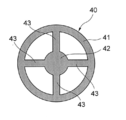
- FIG. 2 is a view showing the connecting member 40.
- the molding apparatus includes a fixed mold 10 that is a first mold, a movable mold 20 that is a second mold, a nest 30, and a connecting member 40 that is a positioning member.
- the fixed mold 10 fixed to a fixed frame has an optical surface transfer surface 10a and a flange portion transfer surface 10b.
- the movable mold 20 that is movable relative to the fixed mold 10 includes a cylindrical portion 20a and a flange portion 20b that is formed so as to block the fixed mold 10 side end of the cylindrical portion 20a.
- a cylindrical opening 20c is formed at the center of the flange portion 20b, and a flange portion transfer surface 20d is formed around the opening 20c so as to face the flange portion transfer surface 10b of the fixed mold 10.
- the substantially cylindrical insert 30 accommodated in the cylindrical portion 20a of the movable mold 20 has a shape in which a large diameter portion 30a and a small diameter portion 30b are joined in series, and the small diameter portion 30b is formed in the cylindrical opening 20c. Are fitted and arranged so that they can slide relative to each other.
- the small diameter portion 30b has an optical surface transfer surface 30c facing the optical surface transfer surface 10a of the fixed mold 10.
- a spring member 31 is disposed around the small-diameter portion 30b and between the flange portion 20b of the movable mold 20 and the end surface of the large-diameter portion 30a of the insert 30 facing the flange portion 20b. In contrast, the nesting 30 is biased to the left in FIG.
- the connecting member 40 is formed of a stainless steel plate, and as shown in FIG. 2, the outer ring part (fixed part) 41, the central disk part (contact part) 42, the ring part 41 and the disk part 42. And four straight connecting portions (connecting portions) 43 that are arranged in the radial direction.
- the connecting member 40 is attached to the insert 30 by fixing the disk portion 42 to the end surface of the large-diameter portion 30a of the insert 30, and further, the ring zone portion 41 is fixed to the end surface of the cylindrical portion 20a of the movable mold 20. It is attached to the movable mold 20. Thereby, the movable mold
- various modes such as screwing, adhesion
- the movable mold 20 to which the connecting member 40 is attached is further attached to the flat end surface of the movable frame 50.
- the movable frame 50 can be moved toward and away from the fixed mold 10 by a drive source (not shown).
- An opening 50a is formed in the center of the end face of the movable frame 50, and an eject pin 51 is disposed in the opening 50a.
- the eject pin 51 is opposed to the disk portion 42 of the connecting member 40 attached to the movable mold 20 and is pushed out in the left-right direction in FIG. 1 with respect to the movable frame 50 by an electric toggle mechanism (not shown) or a hydraulic cylinder. It can be pulled in.
- the eject pin 51 is in the retracted position shown in FIG. 1B, the insert 30 is in the molding position, and when it is in the push-out position shown in FIG. 1C, the insert 30 is in the protruding position.
- the movable mold 20 is abutted against and brought into close contact with the fixed mold 10, and clamping is performed with a predetermined holding pressure. Further, by heating the fixed mold 10 and the movable mold 20 with a heater (not shown), the optical surface transfer surfaces 10a and 30a at the time of mold clamping are heated to a predetermined temperature, and then arbitrarily set from a nozzle (not shown) through a gate. The resin is supplied in a state in which the pressure is increased. Next, after the molten resin is solidified in a state where the shapes of the optical surface transfer surfaces 10a and 30c and the flange portion transfer surfaces 10b and 20d are transferred, the mold temperature is lowered to cool and solidify the resin.
- the movable frame 50 is moved to the left in the drawing, and the movable mold 20 is separated from the fixed mold 10 to be stationary. At this time, since the eject pin 51 moves together with the movable frame 50, the insert 30 remains in the molding position.
- the elastic deformation of the straight connecting portion 43 is returned by the movement of the eject pin 51 to the retracted position, and the internal stress generated by the elastic deformation disappears. Since it returns to the position, a predetermined restoring force can be exhibited, and the large-diameter portion 30a of the insert 30 can be accurately positioned with respect to the cylindrical portion 20a of the movable mold 20 in the direction orthogonal to the axis. Accordingly, since the optical axes of the optical surface transfer surfaces 10a and 30c are not shifted every time the molding is performed, a good molding reproducibility can be realized when the molding is returned to the state of FIG. An accurate optical element can be molded stably.
- a certain amount of gap is provided between the small-diameter portion 30b of the insert 30 and the opening 20c of the movable mold 20 so that relative movement is possible.
- the resin leaks out and causes burrs and the like.
- This gap occurs on both sides of the opening 20c across the small diameter portion 30b.
- the small diameter portion 30b is biased in the opening 20c, which is easy. Exceeds the allowable value.
- the resin can be obtained even if the total gap between the small diameter portion 30b and the opening 20c is relatively large. There is also an effect that it becomes difficult to leak.
- the connecting member 40 can also be formed from a shape memory alloy. In such a case, the original shape as shown in FIG. 1A can be restored by changing the temperature from the state of FIG. In such a case, the spring member 31 becomes unnecessary.
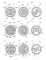
- FIG. 3 is a view showing a modification of the connecting member according to the present embodiment.
- the connecting member 40 in FIG. 3A is provided with an intermediate annular zone 44 between the annular zone 41 and the disc portion 42, and two between the annular zone 41 and the intermediate annular zone 44. It connects with the straight connection part 43a, and connects between the intermediate ring zone part 44 and the disk part 42 in the orthogonal direction with the two straight connection parts 43b.
- the connecting member 40 in FIG. 3B is provided with a first intermediate ring zone portion 44a and a second intermediate ring zone portion 44b between the ring zone portion 41 and the disc portion 42.
- the intermediate ring zone portion 44a is connected by two straight connection portions 43a
- the first intermediate ring zone portion 44a and the second intermediate ring zone portion 44b are connected by two straight connection portions 43b in the orthogonal direction.
- the second intermediate ring zone part 44b and the disk part 42 are connected in the orthogonal direction by two straight connection parts 43c.
- the deformation allowable amount is larger than that of the connecting member 40 shown in FIG. 3A, and thus the protrusion amount can be increased.
- the connecting member 40 in FIG. 3C is provided with an intermediate annular zone 44 between the annular zone 41 and the disk portion 42, and four between the annular zone 41 and the intermediate annular zone 44. It connects with the straight connection part 43a, and connects between the intermediate
- the connecting member 40 in FIG. 3D is provided with an intermediate annular zone 44 between the annular zone 41 and the disk portion 42, and a single zone between the annular zone 41 and the intermediate annular zone 44.
- the straight connection part 43a is connected in the radial direction, and the intermediate ring zone part 44 and the disk part 42 are connected in the orthogonal direction by a single straight connection part 43b.
- connection member 40 of FIG.3 (e) has connected between the zone part 41 and the disk part 42 with the one spiral connection part 43.
- FIG. The allowable deformation amount is larger than that of the connecting member 40 shown in FIG. 3B, and thus the protrusion amount can be increased.
- the disk part 42 rotates around the axis line according to the protrusion amount of the disk part 42 from the ring zone part 41.
- 3 (f) is provided with an intermediate annular zone 44 between the annular zone 41 and the disc portion 42, and two between the annular zone 41 and the intermediate annular zone 44. It connects with the straight connection part 43a, and connects between the intermediate ring zone part 44 and the disk part 42 in the diagonal direction with the four straight connection parts 43b.
- the ring zone portion 41 and the disk portion 42 are connected by two connecting portions 43, but the pair of connecting portions 43 are arranged point-symmetrically.
- the straight portion and the quarter arc portion are formed.
- the disk part 42 rotates around the axis line according to the protrusion amount of the disk part 42 from the ring zone part 41.
- the ring zone portion 41 and the disc portion 42 are connected by two connecting portions 43, but the pair of connecting portions 43 are arranged symmetrically.
- the straight part and the semicircular arc part are formed.
- the ring zone portion 41 and the disk portion 42 are connected by two connecting portions 43, but the pair of connecting portions 43 are arranged point-symmetrically.
- the straight part and the S-shaped part are formed.
- the disk part 42 rotates around the axis line according to the protrusion amount of the disk part 42 from the ring zone part 41.
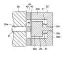
- FIG. 4 is a cross-sectional view of a molding apparatus according to another embodiment.
- two connecting members 40 are used. More specifically, for example, two connecting members 40 shown in FIG. 2 are mutually connected in a parallel state in which a peripheral spacer 45 is interposed between ring zones and a central spacer 46 is interposed between disk portions. This is fixed to the movable mold 20 in the same manner as described above. In such a configuration, the straight connecting portions 43 of the pair of connecting members 40 maintain a parallel state even when deformed, and thus there is an advantage that the inclination of the nest 30 can be suppressed. Since the other configuration is the same as that of the above-described embodiment, the description thereof is omitted.
- the positioning member of the present invention is not limited to the above.
- the small diameter portion 30b of the insert 30 at the molding position may be centered with respect to the opening 20c of the movable mold 20, or the movable mold 20
- a cylindrical porous pad is inserted into the opening 20c, and the static pressure formed on the entire circumference is obtained by pumping air from an external air pressure source to the porous pad with the small diameter portion 30b inserted.
- the small diameter portion 30b of the insert 30 may be centered with respect to the opening 20c of the movable mold 20.
- the mechanism for returning the insert to the molding position is a return pin (the pin that protrudes to the PL surface side of the movable die after the product is removed hits the fixed die when the die is clamped, and the protruding pin inserts the insert.
- a mechanism that mechanically exerts a predetermined restoring force such as a mechanism that pushes back and a pin that protrudes the nest has a shape that is hooked on the nest and pulls the nest with the pin and returns it to the molding position.
- the present invention it is possible to provide a molding apparatus capable of suppressing the shift between the mold and the insert, but the insert may be provided in the fixed mold. Further, the object of molding is not limited to an optical element, and various products are targeted.
Landscapes
- Engineering & Computer Science (AREA)
- Manufacturing & Machinery (AREA)
- Mechanical Engineering (AREA)
- Health & Medical Sciences (AREA)
- Ophthalmology & Optometry (AREA)
- Moulds For Moulding Plastics Or The Like (AREA)
Abstract
型と入れ子のシフトを抑制できる成形装置を提供する。前記成形装置において、入れ子30が成形位置に復帰すると、ストレート連結部43の弾性変形が戻るため、円盤部42は輪帯部41に対して元の位置に戻り、これにより可動型20の円筒部20aに対して入れ子30の大径部30aを精度良く位置決めすることができる。
Description
本発明は、成形装置に関し、光学素子の射出成形等に好適な成形装置に関する。
樹脂の射出成形により光学素子を成形すると、高精度な形状を有する光学素子を大量生産できるというメリットがある。成形装置の一タイプとして、特許文献1に示すように、固定型に対向する可動型に転写面を形成した入れ子を嵌合させ、成形後に可動型から入れ子を突き出して成形品を取り出すことができるものが知られている。
ところで、可動型に対して入れ子を相対移動可能とするためには、ある程度のクリアランスが必要でなる。しかるに、可動型に対して入れ子が突き出した後、次の成形を行う前に、入れ子を元の状態に復帰させる必要があるが、可動型と入れ子との間に過大なクリアランスがあると、復帰毎に可動型と入れ子との相対位置が変化してズレが生じ、成形の再現性が悪化することとなる。即ち、固定型と入れ子の転写面同士の軸線が互いにシフトすることで、例えば光学素子用の成形装置の場合など、過大なコマ収差を発生させる光学素子が成形される恐れがある。特に、近年において開発されたBlu-ray Disc用の光ピックアップ装置などに用いる対物レンズのように、高NAで高精度な光学素子においては、コマ収差の許容度が非常に低く、より高精度な成形を行える成形装置が望まれている。
本発明は、かかる従来技術の問題点に鑑みてなされたものであり、型と入れ子のシフトを抑制できる成形装置を提供することを目的とする。
請求項1に記載の成形装置は、
第1の成形転写面を備えた第1の型と、
前記第1の型に対して相対的に移動可能な第2の型と、
前記第1の成形転写面に対向して第2の成形転写面を備え、前記第2の型に対して、成形位置と突き出し位置との間で相対的に移動可能となっている入れ子と、
前記第2の型と前記入れ子との間に配置され、所定の復元力を発生することにより、前記成形位置へと戻ったとき、前記第2の型に対して、前記入れ子の移動方向と直交する方向に前記入れ子を位置決めする位置決め部材と、を有することを特徴とする。
第1の成形転写面を備えた第1の型と、
前記第1の型に対して相対的に移動可能な第2の型と、
前記第1の成形転写面に対向して第2の成形転写面を備え、前記第2の型に対して、成形位置と突き出し位置との間で相対的に移動可能となっている入れ子と、
前記第2の型と前記入れ子との間に配置され、所定の復元力を発生することにより、前記成形位置へと戻ったとき、前記第2の型に対して、前記入れ子の移動方向と直交する方向に前記入れ子を位置決めする位置決め部材と、を有することを特徴とする。
本発明によれば、前記第2の型と前記入れ子との間に配置された前記位置決め部材が、所定の復元力を発生することにより、前記成形位置へと戻ったとき、前記第2の型に対して、前記入れ子の移動方向と直交する方向に前記入れ子を位置決めするので、前記第2の型と前記入れ子との間のクリアランスに関わらず、成形位置では常に精度良い関係を維持することが出来、これにより高精度な成形を行うことができる。特に微細な回折構造を有するレンズ、例えばBlu-ray Disc(BD)専用レンズ及びBD三互換レンズ等の場合に本発明の効果が期待される。
請求項2に記載の成形装置は、請求項1に記載の発明において、前記位置決め部材は板材から形成されており、前記第2の型に固定される固定部と、前記入れ子に当接する当接部と、前記固定部と前記当接部とを連結し、前記第2の型に対して前記入れ子が前記突き出し位置に移動した時に変形する連結部とを有することを特徴とするので、簡素な構成で低コストでありながら、高精度な成形を実現できる。
請求項3に記載の成形装置は、請求項1又は2に記載の発明において、前記位置決め部材は、複数の板材から構成されていることを特徴とする。これにより、前記入れ子の倒れを有効に抑制できる。
請求項4に記載の成形装置は、請求項1~3のいずれかに記載の発明において、前記位置決め部材はステンレス鋼から形成されていることを特徴とする。例えば、ステンレス鋼を用いて第2の型や入れ子を形成した場合、前記位置決め部材を同じステンレス鋼から形成すると、熱膨張率など物性が近い為、温度が上昇したときに各部に生じる歪み等が小さくなり、また耐久性にも優れる。
請求項5に記載の成形装置は、請求項1~3のいずれかに記載の発明において、前記位置決め部材は高分子材料から形成されていることを特徴とする。高分子材料としては、例えばJIS B2401 4種Dのゴム等を用いることができるが、それに限られない。
請求項6に記載の成形装置は、請求項1~3のいずれかに記載の発明において、前記位置決め部材は形状記憶合金から形成されていることを特徴とする。形状記憶合金が元の形状に戻る性質を有することを利用して、第2の型に対して入れ子を位置決めすることができる。
位置決め部材は、以上に限られず、例えばピエゾ素子や静圧軸受等などを用いても良い。
本発明によれば、型と入れ子のシフトを抑制できる成形装置を提供することができる。
以下、図面を参照して本発明の実施の形態について説明する。図1は、光学素子としてのレンズを、本実施の形態にかかる成形装置を用いて成形する工程を示す図である。図2は連結部材40を示す図である。成形装置は、第1の型である固定型10と、第2の型である可動型20と、入れ子30と、位置決め部材である連結部材40とを含む。
不図示の固定フレーム等に固定された固定型10は、光学面転写面10aとフランジ部転写面10bとを有する。固定型10に対して相対的に移動可能となっている可動型20は、円筒部20aと、円筒部20aの固定型10側端を塞ぐように形成されたフランジ部20bとを有する。フランジ部20bの中央には、円筒状の開口20cが形成され、開口20cの周囲において固定型10のフランジ部転写面10bに対向して、フランジ部転写面20dが形成されている。
可動型20の円筒部20a内に収容される略円筒状の入れ子30は、大径部30aと小径部30bとを直列に接合した形状を有し、小径部30bは、円筒状の開口20c内に嵌合配置され、相対摺動可能となっている。小径部30bは、固定型10の光学面転写面10aに対向して、光学面転写面30cを有する。尚、小径部30bの周囲であって、可動型20のフランジ部20bと、それに対向する入れ子30の大径部30aの端面との間には、バネ部材31が配置されており、フランジ部20bに対して入れ子30を図1で左方に付勢している。
連結部材40は、ステンレス鋼板から形成され、図2に示すように、外周の輪帯部(固定部)41と、中央の円盤部(当接部)42と、輪帯部41と円盤部42とを半径方向に連結する4本の等配されたストレート連結部(連結部)43とからなる。
連結部材40は、円盤部42を入れ子30の大径部30aの端面に固定することで、入れ子30に取り付けられ、更に輪帯部41を可動型20の円筒部20aの端面に固定することで、可動型20に取り付けられる。これにより、可動型20と入れ子30とは連結部材40で連結されて一体となる。ここで、可動型20と入れ子30と連結部材40との固定は、ねじ止め、接着、溶接、挟み込みなど種々の態様が考えられる。
図1において、連結部材40を取り付けた可動型20は、更に可動フレーム50の平らな端面に取り付けられている。可動フレーム50は、不図示の駆動源により固定型10に対して接近・離反可能となっている。可動フレーム50の前記端面の中央には、開口50aが形成され、開口50a内にはイジェクトピン51が配置されている。イジェクトピン51は、可動型20に取り付けた連結部材40の円盤部42に対向しており、不図示の電動トグル機構や油圧シリンダ等により、可動フレーム50に対して図1で左右方向に押し出しもしくは引き込み可能となっている。イジェクトピン51が、図1(b)に示す引き込み位置にあるときには、入れ子30は成形位置にあり、図1(c)に示す押し出し位置にあるときには、入れ子30は突き出し位置にある。
次に、本成形装置を用いた光学素子の成形工程について説明する。まず、図1(a)に示すように、入れ子30を成形位置として、可動型20を固定型10に突き合わせて密着させ、所定の保圧にて型締めを行う。更に固定型10と可動型20とを不図示のヒータにより加熱することにより、型締め時点での光学面転写面10a、30aを所定温度まで加熱した後、不図示のノズルからゲートを介して任意の圧力に加圧された状態で樹脂を供給する。次に、溶融した樹脂が光学面転写面10a、30c,フランジ部転写面10b、20dの形状を転写した状態で固化した後、型温度を低下させて樹脂を冷却して固化させる。
その後、図1(b)に示すように、可動フレーム50を図で左方に移動させ、固定型10から可動型20を離反させて静止させる。このとき、イジェクトピン51は可動フレーム50と一体で移動するため、入れ子30は成形位置のままである。
次いで、図1(c)に示すように、イジェクトピン51を押し出し位置へと移動させ、開口50aから突き出すようにすると、その先端が、連結部材40の円盤部42を介して入れ子30の端面を押圧することとなる。これにより入れ子30は、バネ部材31の付勢力に抗して突き出し位置へと移動するので、入れ子30の突き出しにより、成形された光学素子OEは可動型20から剥がれ、容易に取り出すことができる。このとき、輪帯部41と円盤部42とを連結する4本のストレート連結部43は、イジェクトピン51の突き出しに応じて弾性変形する。
その後、イジェクトピン51を引き込み位置へと移動させると、入れ子30はバネ部材31の付勢力により押し戻され、それにより図1(b)に示す左方の成形位置へと復帰する。このとき、連結部材40のストレート連結部43は、可動フレーム50の端面に当接することによって、光軸方向における可動型20に対する入れ子30の位置決めを精度良く行うことができる。
一方、イジェクトピン51の引き込み位置への移動により、ストレート連結部43の弾性変形が戻り、弾性変形により生じた内部応力が消失するようにして、円盤部42も輪帯部41に対して元の位置に戻るから、これにより所定の復元力を発揮して、可動型20の円筒部20aに対して入れ子30の大径部30aを軸線直交方向に精度良く位置決めすることができる。従って、成形毎に光学面転写面10a、30cの光軸がシフトすることがなくなるので、更に図1(a)の状態に戻って成形した場合に良好な成形再現性を実現出来、これにより高精度な光学素子を安定して成形できることとなる。
特に、入れ子30の小径部30bと、可動型20の開口20cとの間には、相対移動を可能とすべくある程度の隙間を設けているが、かかる隙間が許容値を超えると、成形時に隙間から樹脂が漏れ出してバリなどを生じさせることとなる。この隙間は、小径部30bを挟んで開口20cの両側に生じるが、入れ子30と可動型20との間に軸線直交方向のシフトが生じると、小径部30bが開口20c内で偏ってしまい、容易に許容値を超えてしまう。本実施の形態のように、連結部材40を用いて成形時における可動型20に対する入れ子30の位置決めを行えば、小径部30bと開口20cとの間の合計隙間を比較的大きくしても、樹脂が洩れにくくなるという効果もある。
尚、連結部材40を形状記憶合金から形成することもできる。かかる場合、図1(c)の状態から温度を変化させることで、図1(a)に示すような元の形状に復帰させることが出来る。かかる場合には、バネ部材31が不要となる。
図3は、本実施の形態にかかる連結部材の変形例を示す図である。図3(a)の連結部材40は、輪帯部41と、円盤部42との間に、中間輪帯部44を設け、輪帯部41と中間輪帯部44との間を2本のストレート連結部43aで連結し、中間輪帯部44と円盤部42との間を2本のストレート連結部43bで直交方向に連結している。
図3(b)の連結部材40は、輪帯部41と、円盤部42との間に、第1中間輪帯部44aと第2中間輪帯部44bを設け、輪帯部41と第1中間輪帯部44aとの間を2本のストレート連結部43aで連結し、第1中間輪帯部44aと第2中間輪帯部44bとの間を2本のストレート連結部43bで直交方向に連結し、第2中間輪帯部44bと円盤部42との間を2本のストレート連結部43cで直交方向に連結している。図3(a)に示す連結部材40よりも変形許容量が大きく、よって突き出し量を増大できる。
図3(c)の連結部材40は、輪帯部41と、円盤部42との間に、中間輪帯部44を設け、輪帯部41と中間輪帯部44との間を4本のストレート連結部43aで連結し、中間輪帯部44と円盤部42との間を2本のストレート連結部43bで斜め方向に連結している。
図3(d)の連結部材40は、輪帯部41と、円盤部42との間に、中間輪帯部44を設け、輪帯部41と中間輪帯部44との間を1本のストレート連結部43aで半径方向に連結し、中間輪帯部44と円盤部42との間を1本のストレート連結部43bで直交方向に連結している。
図3(e)の連結部材40は、輪帯部41と、円盤部42との間を、1本の渦巻き状の連結部43で連結している。図3(b)に示す連結部材40よりも更に変形許容量が大きく、よって突き出し量を増大できる。また、本変形例では、輪帯部41からの円盤部42の突出量に応じて、円盤部42が軸線回りに回転する。
図3(f)の連結部材40は、輪帯部41と、円盤部42との間に、中間輪帯部44を設け、輪帯部41と中間輪帯部44との間を2本のストレート連結部43aで連結し、中間輪帯部44と円盤部42との間を4本のストレート連結部43bで斜め方向に連結している。
図3(g)の連結部材40は、輪帯部41と、円盤部42との間を、2本の連結部43で連結しているが、一対の連結部43は点対称的に配置され、ストレート部と1/4円弧部とから形成されている。また、本変形例では、輪帯部41からの円盤部42の突出量に応じて、円盤部42が軸線回りに回転する。
図3(h)の連結部材40は、輪帯部41と、円盤部42との間を、2本の連結部43で連結しているが、一対の連結部43は線対称的に配置され、ストレート部と半円弧部とから形成されている。
図3(i)の連結部材40は、輪帯部41と、円盤部42との間を、2本の連結部43で連結しているが、一対の連結部43は点対称的に配置され、ストレート部とS字状部とから形成されている。また、本変形例では、輪帯部41からの円盤部42の突出量に応じて、円盤部42が軸線回りに回転する。
図4は別な実施の形態にかかる成形装置の断面図である。本実施の形態においては、2枚の連結部材40を用いている。より具体的には、例えば図2に示す連結部材40を2つ、その輪帯部間に周囲間座45を介在させ,且つ円盤部間に中央間座46を介在させた平行な状態で相互に固定し、これを可動型20に上述と同様に取り付ける。かかる構成では、一対の連結部材40のストレート連結部43が、変形時にも平行状態を維持するので、入れ子30の傾きを抑制できるというメリットがある。それ以外の構成は上述した実施の形態と同様であるため説明を省略する。
本発明の位置決め部材は、以上に限られない、例えばピエゾ素子を用いて、可動型20の開口20cに対して、成形位置における入れ子30の小径部30bをセンタリングさせても良いし、可動型20の開口20c内に円管状の多孔質パッドを嵌入し、小径部30bを挿通した状態で、多孔質パッドに外部の空気圧源から空気を圧送することで全周に形成される静圧を用いて、可動型20の開口20cに対して、入れ子30の小径部30bをセンタリングさせても良い。又、入子を成形位置に戻す機構はバネ以外にも、リターンピン(製品取り出し後、可動側型のPL面側に突き出たピンが型締め時に固定側の型に当たり、突き出たピンが入れ子を押し戻す機構)や、入れ子を突き出すピンが入れ子に引っかかる形状をしている場合、そのピンで入れ子を引っ張って成形位置へ戻す、といった所定の復元力を機械的に発揮する機構もある。
本発明によれば、型と入れ子のシフトを抑制できる成形装置を提供することができるが、入れ子は固定型に設けても良い。又、成形の対象は光学素子に限られず、種々の製品が対象になる。
10 固定型
10a 光学面転写面
10b フランジ部転写面
20 可動型
20a 円筒部
20b フランジ部
20c 開口
20d フランジ部転写面
30 入れ子
30a 大径部
30b 小径部
30c 光学面転写面
31 バネ部材
40 連結部材
41 輪帯部
42 円盤部
43 ストレート連結部又は連結部
43a ストレート連結部
43b ストレート連結部
43c ストレート連結部
44 中間輪帯部
44a 第1中間輪帯部
44b 第2中間輪帯部
45 周囲間座
46 中央間座
50 可動フレーム
50a 開口
51 イジェクトピン
OE 光学素子
10a 光学面転写面
10b フランジ部転写面
20 可動型
20a 円筒部
20b フランジ部
20c 開口
20d フランジ部転写面
30 入れ子
30a 大径部
30b 小径部
30c 光学面転写面
31 バネ部材
40 連結部材
41 輪帯部
42 円盤部
43 ストレート連結部又は連結部
43a ストレート連結部
43b ストレート連結部
43c ストレート連結部
44 中間輪帯部
44a 第1中間輪帯部
44b 第2中間輪帯部
45 周囲間座
46 中央間座
50 可動フレーム
50a 開口
51 イジェクトピン
OE 光学素子
Claims (6)
- 第1の成形転写面を備えた第1の型と、
前記第1の型に対して相対的に移動可能な第2の型と、
前記第1の成形転写面に対向して第2の成形転写面を備え、前記第2の型に対して、成形位置と突き出し位置との間で相対的に移動可能となっている入れ子と、
前記第2の型と前記入れ子との間に配置され、所定の復元力を発生することにより、前記成形位置へと戻ったとき、前記第2の型に対して、前記入れ子の移動方向と直交する方向に前記入れ子を位置決めする位置決め部材と、を有することを特徴とする成形装置。 - 前記位置決め部材は板材から形成されており、前記第2の型に固定される固定部と、前記入れ子に当接する当接部と、前記固定部と前記当接部とを連結し、前記第2の型に対して前記入れ子が前記突き出し位置に移動した時に変形する連結部とを有することを特徴とする請求項1に記載の成形装置。
- 前記位置決め部材は、複数の板材から構成されていることを特徴とする請求項1又は2に記載の成形装置。
- 前記位置決め部材はステンレス鋼から形成されていることを特徴とする請求項1から3のいずれかに記載の成形装置。
- 前記位置決め部材は高分子材料から形成されていることを特徴とする請求項1から3のいずれかに記載の成形装置。
- 前記位置決め部材は形状記憶合金から形成されていることを特徴とする請求項1から3のいずれかに記載の成形装置。
Priority Applications (1)
| Application Number | Priority Date | Filing Date | Title |
|---|---|---|---|
| JP2011508271A JPWO2010116792A1 (ja) | 2009-03-30 | 2010-02-16 | 成形装置 |
Applications Claiming Priority (2)
| Application Number | Priority Date | Filing Date | Title |
|---|---|---|---|
| JP2009082299 | 2009-03-30 | ||
| JP2009-082299 | 2009-03-30 |
Publications (1)
| Publication Number | Publication Date |
|---|---|
| WO2010116792A1 true WO2010116792A1 (ja) | 2010-10-14 |
Family
ID=42936080
Family Applications (1)
| Application Number | Title | Priority Date | Filing Date |
|---|---|---|---|
| PCT/JP2010/052256 Ceased WO2010116792A1 (ja) | 2009-03-30 | 2010-02-16 | 成形装置 |
Country Status (2)
| Country | Link |
|---|---|
| JP (1) | JPWO2010116792A1 (ja) |
| WO (1) | WO2010116792A1 (ja) |
Cited By (1)
| Publication number | Priority date | Publication date | Assignee | Title |
|---|---|---|---|---|
| WO2015133645A1 (ja) * | 2014-03-07 | 2015-09-11 | オリンパス株式会社 | 成形金型及び成形金型を用いる製造方法 |
Citations (4)
| Publication number | Priority date | Publication date | Assignee | Title |
|---|---|---|---|---|
| JP2001341134A (ja) * | 2000-06-01 | 2001-12-11 | Konica Corp | 成形型、成形装置、成形方法、射出成形機、射出圧縮成形機、圧縮成形機及びガラス成形機 |
| JP2003175532A (ja) * | 2002-12-18 | 2003-06-24 | Toshin Seiko:Kk | プラスチック光学レンズ用射出成形金型ならびにプラスチック光学レンズの製造方法 |
| JP2007125809A (ja) * | 2005-11-04 | 2007-05-24 | Alps Electric Co Ltd | レンズ成形金型装置 |
| JP2007164058A (ja) * | 2005-12-16 | 2007-06-28 | Nikon Corp | 光学基材、金型、及び複合型光学部品の製造方法 |
-
2010
- 2010-02-16 WO PCT/JP2010/052256 patent/WO2010116792A1/ja not_active Ceased
- 2010-02-16 JP JP2011508271A patent/JPWO2010116792A1/ja active Pending
Patent Citations (4)
| Publication number | Priority date | Publication date | Assignee | Title |
|---|---|---|---|---|
| JP2001341134A (ja) * | 2000-06-01 | 2001-12-11 | Konica Corp | 成形型、成形装置、成形方法、射出成形機、射出圧縮成形機、圧縮成形機及びガラス成形機 |
| JP2003175532A (ja) * | 2002-12-18 | 2003-06-24 | Toshin Seiko:Kk | プラスチック光学レンズ用射出成形金型ならびにプラスチック光学レンズの製造方法 |
| JP2007125809A (ja) * | 2005-11-04 | 2007-05-24 | Alps Electric Co Ltd | レンズ成形金型装置 |
| JP2007164058A (ja) * | 2005-12-16 | 2007-06-28 | Nikon Corp | 光学基材、金型、及び複合型光学部品の製造方法 |
Cited By (5)
| Publication number | Priority date | Publication date | Assignee | Title |
|---|---|---|---|---|
| WO2015133645A1 (ja) * | 2014-03-07 | 2015-09-11 | オリンパス株式会社 | 成形金型及び成形金型を用いる製造方法 |
| CN106103038A (zh) * | 2014-03-07 | 2016-11-09 | 奥林巴斯株式会社 | 成型模具和使用成型模具的制造方法 |
| US20160368193A1 (en) * | 2014-03-07 | 2016-12-22 | Olympus Corporation | Molding die and manufacturing method using molding die |
| JPWO2015133645A1 (ja) * | 2014-03-07 | 2017-04-06 | オリンパス株式会社 | 成形金型及び成形金型を用いる製造方法 |
| CN106103038B (zh) * | 2014-03-07 | 2018-01-23 | 奥林巴斯株式会社 | 成型模具和使用成型模具的制造方法 |
Also Published As
| Publication number | Publication date |
|---|---|
| JPWO2010116792A1 (ja) | 2012-10-18 |
Similar Documents
| Publication | Publication Date | Title |
|---|---|---|
| JP4525868B2 (ja) | 光ピックアップ用対物レンズの製造方法及び光ピックアップ用対物レンズの成形金型、並びに、光ピックアップ用対物レンズ | |
| US7833451B2 (en) | Mold and molding method | |
| WO2009122862A1 (ja) | 光学素子の製造方法、光学素子成形金型、及び光学素子 | |
| CN101909842A (zh) | 光学元件的制造方法及光学元件成形模具 | |
| KR100999546B1 (ko) | 코어금형 | |
| WO2010116792A1 (ja) | 成形装置 | |
| WO2011077934A1 (ja) | 成形金型及び成形金型の製造方法 | |
| CN101125726B (zh) | 成型模具 | |
| US7594808B2 (en) | Mold and molding method | |
| JP2009255468A (ja) | 2色成形用金型及び2色成形方法 | |
| JP5479704B2 (ja) | 2色成形品とその製造方法 | |
| JP2010221516A (ja) | 成形金型、成形方法、及び光学素子 | |
| JP2011177924A (ja) | 光学素子の成形装置 | |
| JP4495585B2 (ja) | 樹脂レンズの成形型 | |
| JP4773789B2 (ja) | 成形用金型及びその製造方法 | |
| JP4097954B2 (ja) | 光学素子、光学素子成形型及び光学素子成形方法 | |
| JP6637780B2 (ja) | レンズ成形金型用の入れ子およびこれを備えたレンズ成形用金型 | |
| JP4808089B2 (ja) | 光学素子成形方法 | |
| JP5103772B2 (ja) | 光学レンズ射出成形用金型 | |
| CN102844163A (zh) | 成型模具及光学元件的制造方法 | |
| JP2010234637A (ja) | 成形装置 | |
| JP4797544B2 (ja) | 樹脂成形装置 | |
| TWI258416B (en) | Mold assembly allowing core and insert alignment | |
| JP2004291341A5 (ja) | ||
| JP2002264134A (ja) | タイヤの加硫方法およびそれに用いるコア装置 |
Legal Events
| Date | Code | Title | Description |
|---|---|---|---|
| 121 | Ep: the epo has been informed by wipo that ep was designated in this application |
Ref document number: 10761494 Country of ref document: EP Kind code of ref document: A1 |
|
| WWE | Wipo information: entry into national phase |
Ref document number: 2011508271 Country of ref document: JP |
|
| NENP | Non-entry into the national phase |
Ref country code: DE |
|
| 122 | Ep: pct application non-entry in european phase |
Ref document number: 10761494 Country of ref document: EP Kind code of ref document: A1 |