WO2010116779A1 - 梁柱架構体の制振装置 - Google Patents
梁柱架構体の制振装置 Download PDFInfo
- Publication number
- WO2010116779A1 WO2010116779A1 PCT/JP2010/051472 JP2010051472W WO2010116779A1 WO 2010116779 A1 WO2010116779 A1 WO 2010116779A1 JP 2010051472 W JP2010051472 W JP 2010051472W WO 2010116779 A1 WO2010116779 A1 WO 2010116779A1
- Authority
- WO
- WIPO (PCT)
- Prior art keywords
- parallel
- brace
- damper
- rotation support
- damping device
- Prior art date
- Legal status (The legal status is an assumption and is not a legal conclusion. Google has not performed a legal analysis and makes no representation as to the accuracy of the status listed.)
- Ceased
Links
Images




Classifications
-
- E—FIXED CONSTRUCTIONS
- E04—BUILDING
- E04H—BUILDINGS OR LIKE STRUCTURES FOR PARTICULAR PURPOSES; SWIMMING OR SPLASH BATHS OR POOLS; MASTS; FENCING; TENTS OR CANOPIES, IN GENERAL
- E04H9/00—Buildings, groups of buildings or shelters adapted to withstand or provide protection against abnormal external influences, e.g. war-like action, earthquake or extreme climate
- E04H9/02—Buildings, groups of buildings or shelters adapted to withstand or provide protection against abnormal external influences, e.g. war-like action, earthquake or extreme climate withstanding earthquake or sinking of ground
- E04H9/021—Bearing, supporting or connecting constructions specially adapted for such buildings
- E04H9/0237—Structural braces with damping devices
-
- E—FIXED CONSTRUCTIONS
- E04—BUILDING
- E04H—BUILDINGS OR LIKE STRUCTURES FOR PARTICULAR PURPOSES; SWIMMING OR SPLASH BATHS OR POOLS; MASTS; FENCING; TENTS OR CANOPIES, IN GENERAL
- E04H9/00—Buildings, groups of buildings or shelters adapted to withstand or provide protection against abnormal external influences, e.g. war-like action, earthquake or extreme climate
- E04H9/02—Buildings, groups of buildings or shelters adapted to withstand or provide protection against abnormal external influences, e.g. war-like action, earthquake or extreme climate withstanding earthquake or sinking of ground
- E04H9/028—Earthquake withstanding shelters
Definitions
- the present invention relates to a vibration damping device for a beam-column frame structure.
- Patent Document 1 Conventionally, as a vibration damping device for a beam column structure, there is one described in Japanese Patent Laid-Open No. 2003-90144 (Patent Document 1).
- the vibration damping device described in FIG. 2 of Patent Document 1 includes a plastic body fixed to an upper beam, and a pair of braces that connect the plastic body and the lower beam. That is, when the beam column structure is horizontally deformed, the plastic body is deformed, so that the seismic energy can be absorbed, and as a result, the beam column structure can be damped.
- FIG. 1 of Patent Document 1 it is devised so that a compressive force is not applied to the brace.
- the load-deformation characteristic (Q- ⁇ characteristic) when a horizontal repeated load is applied is a slip type (generally, non-spindle type, incomplete Also called an elasto-plastic mold).
- Repeated load addition means that after adding the maximum load in one horizontal direction, the load is decreased, the load in the other horizontal direction is increased, and the load in the other horizontal direction is set as the maximum load. It is to repeat decreasing the applied load in the horizontal direction.
- the slip type the behavior when decreasing the additional load in one horizontal direction and the behavior when increasing the additional load in the other horizontal direction are not continuous, This is a stepped state, that is, a state of slipping. Further, in the case of the slip type, even when the applied load direction is reversed as described above, similarly, it is not continuous but has a stepped shape.
- the load-deformation characteristic at the time of repeated load application is a so-called spindle type (generally also referred to as a complete elasto-plastic type), or closer to the spindle type, the energy absorption capacity is further increased.
- the spindle type the restoring property is improved. That is, in the configuration of FIG. 1 of Patent Document 1, even if the compressive force can be prevented from acting on the brace, if the plastic body is deformed in the axial direction of the brace where the tensile force acts in addition to the shear deformation, the load-deformation Restorability is not good because the characteristics are slip-type.
- Patent Document 2 includes a fixed plate (23) erected on a lower beam and two movable plates (24) supported so as to be swingable so as to sandwich the fixed plate (23).
- a pair of braces (5, 6) cross in the middle vicinity.
- the present invention has been made in view of such circumstances, and has a configuration in which a compressive force does not act on the brace, or a configuration in which the compressive force applied to the brace can be made extremely small, and has high vibration damping performance.
- An object of the present invention is to provide a vibration damping device for a beam-column frame structure that can exhibit the above.
- a vibration damping device for a beam-column structure composed of beams and columns, Provided inside the frame of the beam column structure, provided between the first member and the second member facing each other among the beam and the column, and facing the first member in parallel.
- a parallel member provided as A rotation support member that is provided in a facing space between the first member and the parallel member, and supports the first member and a central portion of the parallel member in a relatively rotatable manner;
- a first brace that connects one end side of the parallel member and one end side of the second member or near one end of the second member; The other end of the parallel member and the other end of the second member or the vicinity of the other end of the second member so as to intersect the first brace when viewed from the front of the frame of the beam column structure.
- a second brace that is connected and provided so that a position where the first brace intersects is located closer to the first member than an intermediate position between the first member and the second member;
- the parallel member and the first member are provided so as to be sandwiched between the parallel member and the first member, and the parallel member and the first member are connected to each other, and are spaced apart from the rotation support member and sandwich the rotation support member.
- a damper member provided on at least one pair on both sides; Is provided.
- the intersection of the first brace and the second brace when viewed from the front of the frame of the beam column structure, is located closer to the first member than the intermediate position between the first member and the second member. ing.
- a horizontal vibration external force is applied to the beam column structure, a tensile force is applied to one of the first and second braces, and a tensile force or a compressive force is not applied to the other.
- a slight compressive force or tensile force is applied.
- a large compressive force can be prevented from acting on the first and second braces.
- the load-deformation characteristic (Q- ⁇ characteristic) when a repeated load is applied becomes a spindle type. Further, even if a compressive force acts on the other brace, the compressive force is very small, so the load-deformation characteristic (Q- ⁇ characteristic) is a characteristic approximate to a spindle type. Therefore, according to this invention, it has high resilience and can exhibit high damping performance.
- the compressive force acts on the brace, so that the secondary moment of the cross-section of the brace has to be increased in order to prevent the brace from buckling.
- the brace can be downsized. Since it is possible to reduce the size of the brace, it is possible to apply a very inexpensive steel rod with a relatively small wire diameter as the brace. Naturally, the ease of assembling the brace is improved.
- the parallel member which comprises this invention is provided in the frame inner side of a beam-column frame structure, is provided between the 1st member and the 2nd member, and is opposed in parallel with respect to the 1st member. Is provided. Further, the rotation support member rotatably supports the parallel member and the first member. Furthermore, at least a pair of damper members are provided between the parallel member and the first member on both sides of the rotation support member.
- the parallel member swings so as to be inclined with respect to the first member.
- one damper member is deformed in a direction to be crushed, and the other damper member is deformed in an extending direction. That is, both of the damper members exhibit a force for restricting and returning the swing of the parallel member and a force for supporting the parallel member with respect to the first member.
- the parallel member is stably supported by the damper member exhibiting the support force of the parallel member in addition to the rotation support member.
- the parallel member is stably supported with respect to the first member by at least a pair of damper members in addition to the rotation support member. Also from this, it is possible to suppress the parallel member from being deformed so as to jump out in the normal direction with respect to the frame plane of the beam column frame.
- the damper member may be a steel damper.
- the steel damper can be easily formed at a relatively low cost among the dampers. Therefore, cost reduction and design freedom can be increased.
- the damper member may be a steel damper that is bent and deformed when the first member and the parallel member are inclined as the beam column structure is deformed. Accordingly, the yield point when the damper member is deformed so as to be crushed and the yield point when the damper member is deformed so as to be extended can be reliably set at desired positions.
- a steel material damper that undergoes compression-tensile deformation is formed in a rectangular parallelepiped shape or a cylindrical shape, and is provided so that one end is fixed to a parallel member and the other end is fixed to a first member.
- a steel damper that undergoes compression-tensile deformation is formed in a rectangular parallelepiped shape or a cylindrical shape, and is provided so that one end is fixed to a parallel member and the other end is fixed to a first member.
- it can also be applied to steel dampers that compress and tension.
- the characteristics at the time of compressive deformation and the characteristics at the time of tensile deformation are different, so the yield point when the damper member is deformed to collapse and the case where the damper member is deformed to stretch It is not easy to set the yield point at a desired position.
- damper member it is preferable to apply a steel damper as described above, but in addition to this, a damper using rubber, incompressible fluid (eg, oil) or the like can also be applied.
- incompressible fluid eg, oil
- the damper member may be formed in a U-shape that opens toward the rotation support member, or a U-shape that opens toward the opposite side of the rotation support member. Good. Thereby, the deformation
- the U-shaped shape is composed of a pair of parallel flat plate portions and arc-shaped curved portions connecting them. That is, the shape does not have an angular portion.
- This damper member can be applied to an angular shape approximate to a U-shape in addition to a U-shape.
- a shape in which the long side portion of the pentagon of the home base shape is an opening, a V shape, and the like In this case, when the damper member is bent and deformed, stress concentration may occur in the angular portion or the V-shaped corner portion that forms the apex of the pentagon, compared to the U-shaped shape. Can be demonstrated.
- the damper member is more preferably U-shaped.
- the damper member is provided in a U-shape so as to be accommodated in the U-shaped first damper member and the U-shape of the first damper member and open in the same direction. It is good to provide the made 2nd damper member. That is, a double U-shaped shape is formed by the first damper member and the second damper member. Thereby, the support rigidity of the parallel member by a damper member can be improved more. In addition, the support rigidity of the parallel member by a damper member is adjusted suitably, and when setting the said support rigidity high, the structure which makes a damper member double is effective.
- each U-shaped damper member when making a damper member into a double U-shaped shape, each U-shaped damper member can be replaced with a pentagonal angular shape or a V-shaped shape.
- a U-shaped shape is preferable.
- the present invention also provides:
- the parallel member is A parallel plate provided spaced apart and parallel to the first member; At least one rib-like member erected on the second member side of the parallel plates so as to extend in a direction perpendicular to the rotation axis of the rotation support member; With One end of the first brace and one end of the second brace may be rotatably connected to the same rib-like member.
- the first brace and the second brace may be attached with a tensile load applied in advance.
- a tensile load is applied to the first and second braces in advance.
- the first and second braces can be prevented from being compressed. Therefore, the load-deformation characteristic (Q- ⁇ characteristic) can be surely made into a spindle type, and a stable state as vibration damping performance can be exhibited.
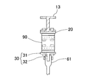
- FIG. 2 is an AA cross-sectional enlarged view of FIG. 1.
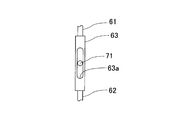
- FIG. 2 is an enlarged cross-sectional view taken along the line BB in FIG.
- FIG. 2 is an enlarged cross-sectional view taken along the line CC of FIG.
- It is a figure of the state which provided horizontal external force to the beam pillar frame.
- It is a figure which shows a load-deformation characteristic (Q-delta characteristic).
- Q-delta characteristic load-deformation characteristic
- 2nd embodiment It is a figure which shows the damping device of a beam-column frame structure.
- FIG. 9 is an enlarged view of a DD section in FIG. 8.
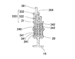
- FIG. 9 is an enlarged cross-sectional view taken along line EE in FIG. 8.
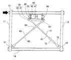
- the beam column frame has a rectangular frame shape. Specifically, the beam column structure is opposed to the upper beam 13, a pair of columns 11 and 12 provided in parallel at a predetermined distance, an upper beam 13 connecting the upper ends of the pair of columns 11 and 12, respectively. And a lower beam 14 that connects the lower ends of the pair of columns 11 and 12 respectively.
- the columns 11 and 12 are square steel pipe columns, and the upper beam 13 and the lower beam 14 are H-shaped steel beams.
- a steel frame structure is taken as an example of the beam column frame structure, but it can also be applied to a lightweight steel frame structure or a wooden frame structure.
- the upper beam 13 corresponds to the first member of the present invention
- the lower beam 14 corresponds to the second member of the present invention.
- the vibration damping device for the beam column structure includes a mounting plate 20, a parallel member 30, a rotation support member 40, first and second gusset plates 51 and 52, a first brace 60, and a second brace 70. And a pair of damper members 80 and 90.
- the mounting plate 20 is made of a rectangular metal flat plate.
- the mounting plate 20 is directly fixed in contact with the lower surface of the upper beam 13.
- the attachment plate 20 is a plate for attaching the rotation support member 40 and the pair of damper members 80 and 90. That is, the mounting plate 20 functions as a reinforcing material for the upper beam 13 and is integrated with the upper beam 13. Therefore, the mounting plate 20 substantially corresponds to a part of the first member of the present invention.
- two through holes are formed on each of the left and right sides of FIG. These through-holes are for inserting bolts for fixing to a pair of damper members 80 and 90 described later. A similar through hole is formed in the upper beam 13 so as to communicate with the through hole.
- the parallel member 30 is provided on the inner side of the frame of the beam column structure, is provided separately between the upper beam 13 and the lower beam 14, and is provided to face the upper beam 13 in parallel. . As shown in FIGS. 1 and 3, the parallel member 30 includes a parallel plate 31 and one rib-like member 32.
- the parallel plate 31 is made of a rectangular metal plate that is substantially the same as the mounting plate 20.
- the parallel flat plate 31 is provided so as to be spaced apart from and parallel to the mounting plate 20 fixed to the upper beam 13.
- Two through holes are formed in each of the parallel plate 31 at the left and right ends in FIG. These through-holes are for inserting bolts for fixing to a pair of damper members 80 and 90 described later.
- the rib-shaped member 32 is erected substantially at the center in the short direction of the parallel plate 31 on the lower surface of the parallel plate 31 (the surface on the lower beam 14 side) so as to extend in a direction parallel to the beams 13 and 14.
- the rib-like member 32 is welded to the parallel plate 31.
- the direction parallel to the beams 13 and 14 is the same as the direction perpendicular to the rotation axis of the rotation support member 40 described later.
- One through hole is formed in each of the left and right ends of FIG. Pins for rotatably supporting first and second braces 60 and 70 described later are inserted through these through holes.
- the rotation support member 40 is provided in a facing space between the mounting plate 20 and the parallel member 30, and the central portion of the mounting plate 20 in FIG. 1 and the central portion of the parallel member 30 in FIG. Support for rotation.
- the rotation support member 40 includes two fixed-side members 41 that are welded so as to be integrated with the mounting plate 20 and two sheets that are welded so as to be integrated with the upper surface of the parallel plate 31 and face each other. And the moving side member 42.
- the fixed side member 41 is provided so that it may be pinched
- the rotation support member 40 allows the parallel member 30 to rotate with respect to the upper beam 13 about the normal direction of the paper surface of FIG.
- the first gusset plate 51 is made of a flat plate in which a through hole is formed, and is welded to the left column 11 and the left end portion of the lower beam 14 in FIG.
- the second gusset plate 52 is formed of a flat plate in which a through hole is formed, and is welded to the right column 12 and the right end portion of the lower beam 14 in FIG.
- the first and second gusset plates 51 and 52 have a function as a member for connecting the first and second braces 60 and 70, and increase the strength of the joint portion between the columns 11 and 12 and the lower beam 14. It has a function.
- the first brace 60 connects the right end side of the rib-like member 32 in FIG. 1 and the first gusset plate 51.
- the first brace 60 includes first and second rods 61 and 62 having fork end portions at one end, and a cross turn buckle that linearly connects the other end of the first rod 61 and the other end of the second rod 62. 63.
- Parts other than the fork end portions of the first and second rods 61 and 62 are made of steel bars having a circular cross section.
- the fork end part of the 1st rod 61 is pin-joined to the through-hole by the side of the right end of FIG. 1 of the rib-shaped member 32 so that it can rotate with respect to the rib-shaped member 32.
- the fork end portion of the second rod 62 is pin-connected to the through hole of the first gusset plate 51 so as to be rotatable with respect to the first gusset plate 51.
- the cross turn buckle 63 has a through hole 63a formed in the center, and first and second rods 61 and 62 are screwed to both ends thereof.
- the second brace 70 connects the left end side of the rib-shaped member 32 in FIG. 1 and the second gusset plate 52.
- the second brace 70 includes first and second rods 71 and 72 having fork end portions at one end, and a turnbuckle 73 that linearly connects the other end of the first rod 71 and the other end of the second rod 72. It consists of. Parts other than the fork end portions of the first and second rods 71 and 72 are made of steel bars having a circular cross section. And the fork end part of the 1st rod 71 is pin-joined to the through-hole by the side of the left end of FIG. 1 of the rib-shaped member 32 so that it can rotate with respect to the rib-shaped member 32.
- first rod 71 passes through the through hole 63 a of the cross turn buckle 63.
- second rod 72 is pin-connected to the through hole of the second gusset plate 52 so as to be rotatable with respect to the second gusset plate 52.
- the other ends of the first and second rods 71 and 72 are screwed to both ends of the turnbuckle 73.
- first brace 60 and the second brace 70 intersect when viewed from the front of the frame of the beam column structure.
- the intersecting position is provided so as to be located on the upper beam 13 side, that is, on the parallel member 30 side from the intermediate position between the upper beam 13 and the lower beam 14.
- the first brace 60 and the second brace 70 are attached in a state where a slight tensile load is applied in advance.
- the pair of damper members 80 and 90 are sandwiched between the mounting plate 20 and the parallel plate 31 and are spaced apart from the rotation support member 40 by an equal distance, respectively, on both sides of the rotation support member 40. Is provided.
- the pair of damper members 80 and 90 connect the mounting plate 20 and the parallel flat plate 31. Specifically, each of both ends of the mounting plate 20 is connected to each of both ends of the parallel plate 31.
- the pair of damper members 80 and 90 are made of a steel damper that is bent and deformed when the upper beam 13 and the parallel flat plate 31 are inclined as the beam column frame is deformed. Specifically, as shown in FIG. 1, the pair of damper members 80 and 90 are formed in a U-shape that opens toward the rotation support member 40.
- the U-shaped shape is composed of a pair of parallel flat plate portions and a portion curved in an arc shape connecting them. That is, the damper members 80 and 90 have a shape that does not have an angular portion.
- the width of the pair of damper members 80 and 90 (horizontal width in FIG. 2) is approximately the same as or slightly shorter than the width of the mounting plate 20 and the parallel plate 31 (horizontal width in FIG. 2). is there. That is, the pair of damper members 80 and 90 have a sufficient width.
- One end of the U shape is fixed to the mounting plate 20 and the upper beam 13 with a bolt, and the other end of the U shape is fixed to the parallel plate 31.
- seat plates are interposed between the damper members 80 and 90 and the mounting plate 20, and between the damper members 80 and 90 and the parallel flat plate 31. This is because the yield points of the damper members 80 and 90 are adjusted to a desired value.
- the parallel flat plate 31 when the parallel flat plate 31 is tilted with respect to the upper beam 13, when the parallel flat plate 31 is deformed so that the separation distance between one end of the parallel flat plate 31 and one end of the mounting plate 20 is small, the parallel flat plate 31 is fixed to the one end.
- the damper member 80 is bent and deformed so as to collapse in the vertical direction in FIG.
- the damper member 90 fixed to the other end portion is arranged in the vertical direction of FIG. Bend and deform to stretch.
- the parallel member 30 tends to move relatively to the right side of FIG. Therefore, the first brace 60 receives a tensile load from the support points at both ends. Thereby, the right end of FIG. 1 of the parallel member 30 is pulled to the first gusset plate 51 side by the first brace 60. Due to the tensile force of the first brace 60, the parallel member 30 tends to rotate clockwise (clockwise) in FIG. 1 about the rotation axis of the rotation support member 40.
- the length of the second brace 70 hardly changes. That is, almost no compressive force or tensile force acts on the second brace 70.
- the first brace 60 receives a tensile load
- the second brace 70 receives almost no load. This behavior is because the intersection of the first brace 60 and the second brace 70 is higher than the intermediate position between the upper beam 13 and the lower beam 14 when viewed from the front of the frame of the beam column frame. This is because it is located on the 13th side.
- the second brace 70 may be subjected to a compressive load very slightly. However, in addition to the very small compressive force, the second brace 70 is preliminarily attached with a tensile load applied, so that it does not undergo any compressive deformation in the first place.
- the vibration damping device for the beam column structure further includes a pair of damper members 80 and 90, thereby exhibiting a vibration damping effect in addition to the earthquake resistance.
- a pair of damper members 80 and 90 which will be described in detail.
- the parallel member 30 rotates about the rotation axis of the rotation support member 40 with respect to the upper beam 13.
- the separation distance between the left end portion of the parallel plate 31 in FIG. 1 and the left end portion of the mounting plate 20 is reduced. Therefore, one damper member 80 is bent and deformed so as to be crushed.
- the separation distance between the right end of FIG. 1 of the parallel plate 31 and the right end of the mounting plate 20 is increased.
- the other damper member 90 is bent and deformed so as to extend. Due to the bending deformation of the damper members 80, 90, the steel material forming the damper members 80, 90 yields and plastically deforms. This absorbs seismic energy and exerts a damping effect.
- the pair of damper members 80 and 90 exhibit a force that returns to their original state when bent and deformed. That is, the damper members 80 and 90 generate a force that causes the parallel member 30 to be parallel to the upper beam 13.
- the load-deformation characteristic (Q- ⁇ characteristic) was obtained by repeatedly applying a horizontal force to this beam-column frame vibration damping device.
- the load-deformation characteristic in the vibration damping device of the beam column structure of the present embodiment is a so-called spindle type.
- the intersection of the first brace 60 and the second brace 70 is from an intermediate position between the upper beam 13 and the lower beam 14 when viewed from the front of the frame of the beam column frame. Is also located on the first member side.
- a horizontal vibration external force is applied to the beam column frame, almost no compressive force is applied to the first and second braces 60 and 70.
- the compressive force is very small. Therefore, the tensile load previously applied to the first and second braces 60 and 70 is reduced. Within range. As a result, substantially only tensile force can act on the first and second braces 60 and 70.
- the load-deformation characteristic when a repeated load is applied becomes a spindle type.
- the load-deformation characteristic can be a spindle type, the resilience is good with respect to repeated loads, and a very high vibration damping performance can be exhibited.
- the spindle type could not be achieved due to the fact that a large compressive force was applied or there was a state in which the elastic force was not exhibited until the tensile force was applied to the other brace. .
- the first and second braces 60 and 70 are applied with no compression force or only a small compression force with respect to the first and second braces 60 and 70.
- the secondary moment of the cross section can be made very small. That is, the first and second braces 60 and 70 can be reduced in size.
- the first and second braces 60 and 70 can be reduced in size, it is possible to apply a very inexpensive steel rod having a relatively small wire diameter as the first and second braces 60 and 70.
- the assembly of the first and second braces 60 and 70 is improved.
- the pair of damper members 80 and 90 exerts a force for regulating and returning the swing of the parallel member 30, and in addition, the parallel member 30. Is exerted on the upper beam 13. Therefore, when the pair of damper members 80 and 90 exhibit the supporting force of the parallel member 30 in addition to the rotation support member 40, the parallel member 30 is stably supported. Therefore, it is possible to suppress the parallel member 30 from being deformed so as to protrude in the normal direction with respect to the frame plane of the beam column frame. Further, as described above, almost no compressive force acts on the first and second braces 60 and 70. Also from this, it is possible to suppress the parallel member 30 from being deformed so as to protrude in the normal direction with respect to the frame plane of the beam column frame.
- the cost can be reduced and the degree of design freedom can be increased.
- the damper members 80 and 90 are made of steel dampers that bend and deform, the yield point when the damper members 80 and 90 are deformed to be crushed and the damper members 80 and 90 are deformed to be extended. The yield point can be reliably set to a desired position.
- the parallel member 30 constitutes the rib-like member 32
- the rib-like member 32 has a role of reinforcing the parallel flat plate 31.
- the parallel member 30 can be stably swung around the rotation axis of the rotation support member 40. That is, it is possible to suppress the parallel member 30 from being twisted with respect to the upper beam 13.
- a torsional load from being applied to the rotation support member 40. That is, even if the support rigidity against the torsion in the rotation support member 40 is not so high, it can be supported sufficiently. Therefore, the structure of the rotation support member 40 can be simplified and reduced in weight.
- FIG. 7A shows a pair of damper members 180 and 190 as a first modification.
- the pair of damper members 180 and 190 are formed in a U-shape that opens toward the opposite side of the rotation support member 40. That is, the pair of damper members 180 and 190 are formed in the same shape as the damper members 80 and 90 of the first embodiment, but the mounting directions are different.
- FIG. 7B shows a pair of damper members 280 and 290 as a second modification. That is, the pair of damper members 280 and 290 are accommodated inside the U-shaped first damper members 281 and 291 and the U-shaped first damper members 281 and 291 and open in the same direction. And second damper members 282 and 292 provided in a U-shape. That is, the first damper members 281 and 291 and the second damper members 282 and 292 form a double U-shape. Thereby, the support rigidity of the parallel member 30 by the damper members 280 and 290 can be further increased.
- the vibration damping device for a beam column structure according to the second embodiment includes a mounting plate 20, a parallel member 330, a rotation support member 340, first and second gusset plates 51 and 52, a first brace 360, Two braces 370 and a pair of damper members 80 and 90 are provided.
- the vibration damping device of the second embodiment is attached to the beam column frame in a state where the vibration damping device of the first embodiment is turned upside down.
- only the configuration different from the vibration damping device of the first embodiment among the vibration damping devices of the second embodiment will be described.
- the parallel member 330 is provided on the inner side of the frame of the beam column structure, is provided separately between the upper beam 13 and the lower beam 14, and is provided so as to face the lower beam 14 in parallel. . As shown in FIGS. 8 to 10, the parallel member 330 includes a parallel plate 31 and two rib-like members 332 and 333.
- the parallel plate 31 is the same as that of the first embodiment, the description thereof is omitted.
- the first and second rib-like members 332 and 333 are erected on the upper surface (surface on the upper beam 13 side) of the parallel plate 31 so as to extend in a direction parallel to the beams 13 and 14.
- the first rib-shaped member 332 is provided on the upper surface of the parallel flat plate 31 from the left end in FIG. 8 to the vicinity of the center in the left-right direction in FIG. 8 and slightly to the left of the center in the left-right direction in FIGS. ing.
- One through hole is formed at the left end of FIG. 8 of the first rib-shaped member 332.
- a pin is inserted through the through hole to rotatably support the first brace 360.
- the second rib-shaped member 333 extends from the right end of FIG. 8 to the vicinity of the center in the left-right direction in FIG. 8 on the upper surface of the parallel plate 31 and slightly to the right of the center in the left-right direction in FIGS. Is provided.
- One through hole is formed at the right end of FIG. 8 of the second rib-shaped member 333.
- a pin is inserted through the through hole to rotatably support the second brace 370.
- the first brace 360 connects the left end side of the first rib-shaped member 332 in FIG. 8 and the first gusset plate 51.
- the first brace 360 includes first and second rods 361 and 362, a turnbuckle 363 that linearly connects one end of the first rod 361 and one end of the second rod 362, and the other end of the first rod 361.
- the first ring joint 364 rotatably provided to the second rod 362 and the second ring joint 365 rotatably provided to the other end of the second rod 362.
- the first ring joint 364 is rotatably connected to the through hole of the first rib-like member 332.
- the second ring joint 365 is rotatably connected to the through hole of the first gusset plate 51. That is, the first brace 360 can swing the first and second ring joints 364 and 365, so that no compression force acts on the first and second rods 361 and 362 and the turnbuckle 363 at all.
- the second brace 370 connects the right end side of the second rib-shaped member 333 in FIG. 8 and the second gusset plate 52.
- the second brace 370 includes a first and second rods 371 and 372, a turnbuckle 373 that linearly connects one end of the first rod 371 and one end of the second rod 372, and the other end of the first rod 371.
- the first ring joint 374 rotatably provided on the second rod 372 and the second ring joint 375 rotatably provided on the other end of the second rod 372.
- the first ring joint 374 is rotatably connected to the through hole of the first rib-like member 332.
- the second ring joint 375 is rotatably connected to the through hole of the second gusset plate 52. That is, since the first and second ring joints 374 and 375 can swing in the second brace 370, no compression force acts on the first and second rods 371 and 372 and the turnbuckle 373 at all.
- first brace 360 and the second brace 370 are slightly shifted when viewed from the right direction in FIG. This is because the first rib-like member 332 and the second rib-like member 333 are provided so as to be displaced in the front-rear direction of FIG. With such a configuration, it is not necessary to use a cross turn buckle as in the first embodiment.
- first brace 360 and the second brace 370 are displaced in the front-rear direction of FIG. 8, when a horizontal external force is applied to the beam column structure, the parallel member 30 is against the lower beam 14. There is a risk of deformation such as twisting.
- the rotation support member 340 is configured to have higher support rigidity than that of the first embodiment.
- the movable member 342 fixed to the parallel member 330 side of the rotation support member 340 is composed of two plates that are opposed to each other in the front-rear direction of FIG. 8.
- the fixed member 341 fixed to the mounting plate 20 side of the rotation support member is composed of three plates that are spaced apart from each other in the front-rear direction of FIG. And it arrange
- the damper members 80, 90, 180, 190, 280, and 290 are U-shaped, but the present invention is not limited to this.
- the damper members 80, 90, 180, 190, 280, and 290 can be applied with a square shape that approximates a U shape in addition to a U shape.
- stress concentration may occur in the angular portion that forms the apex of the pentagon as compared with the U-shaped shape. , Can exert a sufficient effect.
- the damper members 80, 90, 180, 190, 280, and 290 are more preferably U-shaped.
Landscapes
- Engineering & Computer Science (AREA)
- Architecture (AREA)
- Business, Economics & Management (AREA)
- Emergency Management (AREA)
- Environmental & Geological Engineering (AREA)
- Civil Engineering (AREA)
- Structural Engineering (AREA)
- Buildings Adapted To Withstand Abnormal External Influences (AREA)
- Vibration Prevention Devices (AREA)
- Vibration Dampers (AREA)
Abstract
Description
梁と柱とから構成される梁柱架構体の制振装置であって、
前記梁柱架構体の枠内側に設けられ、前記梁および前記柱のうち対向する第一部材と第二部材との間に離隔して設けられ、且つ、前記第一部材に対して平行に対向して設けられた平行部材と、
前記第一部材と前記平行部材との対向空間に設けられ、前記第一部材と前記平行部材の中央部とを相対回転可能に支持する回転支持部材と、
前記平行部材の一端側と前記第二部材の一端側または前記第二部材の一端部近傍とを連結する第一ブレースと、
前記梁柱架構体の枠正面から見た場合に前記第一ブレースと交差するように前記平行部材の他端側と前記第二部材の他端側または前記第二部材の他端部近傍とを連結し、且つ、前記第一ブレースとの交差する位置が前記第一部材と前記第二部材との中間位置よりも前記第一部材側に位置するように設けられる第二ブレースと、
前記平行部材と前記第一部材との間に挟まれるようにそれぞれ設けられ、前記平行部材と前記第一部材とを連結し、且つ、前記回転支持部材からそれぞれ離隔して前記回転支持部材を挟んだ両側に少なくとも一対設けられるダンパー部材と、
を備える。
このように、ダンパー部材を二重のU字型形状とする場合において、各U字型形状のダンパー部材を五角形の角張った形状やV字型の形状に置き換えることもできる。ただし、応力集中の観点から、U字型形状とする方が好ましい。
前記平行部材は、
前記第一部材に対して離隔して且つ平行に対向して設けられた平行平板と、
前記回転支持部材の回転軸に直交する方向に延びるように、前記平行平板のうち前記第二部材側に立設された少なくとも一つのリブ状部材と、
を備え、
前記第一ブレースの一端および前記第二ブレースの一端は、同一の前記リブ状部材に回転可能に連結されるとよい。
これにより、梁柱架構体が変形する際に仮に第一、第二ブレースが僅かに圧縮する方向に力が作用するとしても、第一,第二ブレースに予め引張荷重を付加しておくことで、第一,第二ブレースには圧縮状態にならないようにできる。従って、確実に、荷重-変形特性(Q-δ特性)を紡錘型とすることができ、制振性能として安定した状態を発揮できる。
20:取付プレート
30,330:平行部材、 31:平行平板、 32:リブ状部材
40,340:回転支持部材
41,341:固定側部材、 42,342:移動側部材
60,360:第一ブレース
61,62,361,362:ロッド、 63:クロスターンバックル
70,370:第二ブレース
71,72,371,372:ロッド
73,363,373:ターンバックル
80,90,180,190,280,290:ダンパー部材
281,291:第一ダンパー部材、 282,292:第二ダンパー部材
332:第一リブ状部材、 333:第二リブ状部材
364,365,374,375:リングジョイント
第一実施形態の梁柱架構体の制振装置について、図1~図4を参照して説明する。図1に示すように、梁柱架構体は、矩形枠状を形成している。詳細には、梁柱架構体は、所定距離を隔てて平行に設けられた一対の柱11,12と、一対の柱11,12の上端をそれぞれ連結する上梁13と、上梁13に対向して設けられ一対の柱11,12の下端をそれぞれ連結する下梁14とから構成される。ここで、柱11,12は、角形鋼管柱であり、上梁13および下梁14は、H形鋼梁である。ここでは、梁柱架構体として、鉄骨造を例としてあげるが、この他に、軽量鉄骨造、木造軸組構造にも適用可能である。また、本実施形態においては、上梁13が本発明の第一部材に相当し、下梁14が本発明の第二部材に相当する。
次に、第一実施形態の梁柱架構体の制振装置の変形態様について、二種類説明する。具体的には、一対のダンパー部材80,90のみを変更している。
次に、第二実施形態の梁柱架構体の制振装置について、図8~図10を参照して説明する。第二実施形態の梁柱架構体の制振装置は、取付プレート20と、平行部材330と、回転支持部材340と、第一,第二ガセットプレート51,52と、第一ブレース360と、第二ブレース370と、一対のダンパー部材80,90とを備える。ここで、第二実施形態の当該制振装置は、第一実施形態の制振装置に対して、上下反転させた状態で梁柱架構体に取り付けている。以下、第二実施形態の制振装置のうち、第一実施形態の制振装置と異なる構成のみについて説明する。
上記実施形態においては、平行部材30、330を、回転支持部材40,340を介して上梁13または下梁14に取り付ける例を挙げた。この他に、平行部材を柱11,12に取り付けるようにしても、ほぼ同様の制振効果を奏する。つまり、図1の制振装置を90°回転させたような状態となる。
Claims (7)
- 梁と柱とから構成される梁柱架構体の制振装置であって、
前記梁柱架構体の枠内側に設けられ、前記梁および前記柱のうち対向する第一部材と第二部材との間に離隔して設けられ、且つ、前記第一部材に対して平行に対向して設けられた平行部材と、
前記第一部材と前記平行部材との対向空間に設けられ、前記第一部材と前記平行部材の中央部とを相対回転可能に支持する回転支持部材と、
前記平行部材の一端側と前記第二部材の一端側または前記第二部材の一端部近傍とを連結する第一ブレースと、
前記梁柱架構体の枠正面から見た場合に前記第一ブレースと交差するように前記平行部材の他端側と前記第二部材の他端側または前記第二部材の他端部近傍とを連結し、且つ、前記第一ブレースとの交差する位置が前記第一部材と前記第二部材との中間位置よりも前記第一部材側に位置するように設けられる第二ブレースと、
前記平行部材と前記第一部材との間に挟まれるようにそれぞれ設けられ、前記平行部材と前記第一部材とを連結し、且つ、前記回転支持部材からそれぞれ離隔して前記回転支持部材を挟んだ両側に少なくとも一対設けられるダンパー部材と、
を備えることを特徴とする梁柱架構体の制振装置。 - 請求項1において、
前記ダンパー部材は、鋼材ダンパーであることを特徴とする梁柱架構体の制振装置。 - 請求項2において、
前記ダンパー部材は、前記梁柱架構体の変形に伴って前記第一部材と前記平行部材とが傾く場合に曲げ変形する鋼材ダンパーであることを特徴とする梁柱架構体の制振装置。 - 請求項2または3において、
前記ダンパー部材は、前記回転支持部材に向かって開口するU字型形状、または、前記回転支持部材とは反対側に向かって開口するU字型形状に形成されていることを特徴とする梁柱架構体の制振装置。 - 請求項4において、
前記ダンパー部材は、前記U字型形状の第一ダンパー部材と、第一ダンパー部材のU字型の内部に収容され且つ同方向に開口するようにU字型状に設けられた第二ダンパー部材と、を備えることを特徴とする梁柱架構体の制振装置。 - 請求項1~5の何れか一項において、
前記平行部材は、
前記第一部材に対して離隔して且つ平行に対向して設けられた平行平板と、
前記回転支持部材の回転軸に直交する方向に延びるように、前記平行平板のうち前記第二部材側に立設された少なくとも一つのリブ状部材と、
を備え、
前記第一ブレースの一端および前記第二ブレースの一端は、同一の前記リブ状部材に回転可能に連結されることを特徴とする梁柱架構体の制振装置。 - 請求項1~6の何れか一項において、
前記第一ブレースおよび前記第二ブレースは、予め引張荷重を付加した状態で取り付けられることを特徴とする梁柱架構体の制振装置。
Priority Applications (2)
| Application Number | Priority Date | Filing Date | Title |
|---|---|---|---|
| JP2011508265A JP5515100B2 (ja) | 2009-03-30 | 2010-02-03 | 梁柱架構体の制振装置 |
| US13/260,204 US8677699B2 (en) | 2009-03-30 | 2010-02-03 | Vibration control device for beam-and-column frame |
Applications Claiming Priority (2)
| Application Number | Priority Date | Filing Date | Title |
|---|---|---|---|
| JP2009081222 | 2009-03-30 | ||
| JP2009-081222 | 2009-03-30 |
Publications (1)
| Publication Number | Publication Date |
|---|---|
| WO2010116779A1 true WO2010116779A1 (ja) | 2010-10-14 |
Family
ID=42936068
Family Applications (1)
| Application Number | Title | Priority Date | Filing Date |
|---|---|---|---|
| PCT/JP2010/051472 Ceased WO2010116779A1 (ja) | 2009-03-30 | 2010-02-03 | 梁柱架構体の制振装置 |
Country Status (3)
| Country | Link |
|---|---|
| US (1) | US8677699B2 (ja) |
| JP (1) | JP5515100B2 (ja) |
| WO (1) | WO2010116779A1 (ja) |
Cited By (7)
| Publication number | Priority date | Publication date | Assignee | Title |
|---|---|---|---|---|
| JP2015127489A (ja) * | 2013-12-30 | 2015-07-09 | 株式会社国元商会 | 木造建築物の制振装置 |
| JP2015127488A (ja) * | 2013-12-30 | 2015-07-09 | 株式会社国元商会 | 木造建築物の制振装置 |
| JP2021161764A (ja) * | 2020-03-31 | 2021-10-11 | 旭化成ホームズ株式会社 | 耐震構造 |
| JP2021179085A (ja) * | 2020-05-11 | 2021-11-18 | 三井住友建設株式会社 | 柱梁架構体に設置される制振装置 |
| JP2021179086A (ja) * | 2020-05-11 | 2021-11-18 | 三井住友建設株式会社 | 柱梁架構体に設置される制振装置のタイロッドに引張力を導入する方法 |
| CN113775073A (zh) * | 2021-09-24 | 2021-12-10 | 中衡设计集团股份有限公司 | 一种竖向约束释放的装配式剪切型阻尼器 |
| JP2022182633A (ja) * | 2021-05-28 | 2022-12-08 | アイディールブレーン株式会社 | 制震装置の製造方法及び制震装置 |
Families Citing this family (52)
| Publication number | Priority date | Publication date | Assignee | Title |
|---|---|---|---|---|
| JP5740133B2 (ja) * | 2010-02-16 | 2015-06-24 | 大倉 憲峰 | 締結具 |
| JP6074132B2 (ja) * | 2011-05-27 | 2017-02-01 | 大和ハウス工業株式会社 | 制振ブレース接合構造 |
| US8857110B2 (en) * | 2011-11-11 | 2014-10-14 | The Research Foundation For The State University Of New York | Negative stiffness device and method |
| WO2013149054A1 (en) * | 2012-03-28 | 2013-10-03 | Beard Scott Randall | Staggered truss system with controlled force slip joints |
| JP6107622B2 (ja) * | 2013-06-20 | 2017-04-05 | ブラザー工業株式会社 | 画像形成装置 |
| JP6107623B2 (ja) | 2013-06-20 | 2017-04-05 | ブラザー工業株式会社 | 画像形成装置 |
| JP6135482B2 (ja) | 2013-06-20 | 2017-05-31 | ブラザー工業株式会社 | 画像形成装置 |
| JP6079591B2 (ja) | 2013-06-20 | 2017-02-15 | ブラザー工業株式会社 | 画像形成装置 |
| JP6102703B2 (ja) | 2013-06-20 | 2017-03-29 | ブラザー工業株式会社 | 画像形成装置 |
| JP6098390B2 (ja) | 2013-06-20 | 2017-03-22 | ブラザー工業株式会社 | 画像形成装置 |
| US9206616B2 (en) | 2013-06-28 | 2015-12-08 | The Research Foundation For The State University Of New York | Negative stiffness device and method |
| JP5426048B1 (ja) * | 2013-09-25 | 2014-02-26 | 孝典 佐藤 | 制震壁構造 |
| JP6119582B2 (ja) | 2013-11-15 | 2017-04-26 | ブラザー工業株式会社 | 画像形成装置 |
| US10400469B2 (en) | 2013-12-02 | 2019-09-03 | The Governing Council Of The University Of Toronto | System for mitigating the effects of a seismic event |
| EP3077605A4 (en) * | 2013-12-02 | 2017-08-23 | The Governing Council of the University of Toronto | System for mitigating the effects of a seismic event |
| JP6065825B2 (ja) | 2013-12-24 | 2017-01-25 | ブラザー工業株式会社 | 画像形成装置 |
| JP6065824B2 (ja) | 2013-12-24 | 2017-01-25 | ブラザー工業株式会社 | 画像形成装置 |
| JP6079615B2 (ja) | 2013-12-24 | 2017-02-15 | ブラザー工業株式会社 | 画像形成装置 |
| JP6142796B2 (ja) | 2013-12-24 | 2017-06-07 | ブラザー工業株式会社 | 画像形成装置 |
| US9121321B2 (en) * | 2013-12-31 | 2015-09-01 | Rufus Larry Terrell | Exhaust system passive noise cancellation assembly and method |
| US20150184413A1 (en) * | 2014-01-01 | 2015-07-02 | Steven E. Pryor | Self-Centering Braced Frame for Seismic Resistance in Buildings |
| CN103821248B (zh) * | 2014-03-09 | 2015-11-18 | 北京工业大学 | 限位连杆型低频隔震耗能支撑 |
| DE102014208934B4 (de) * | 2014-05-12 | 2015-11-26 | Siemens Aktiengesellschaft | Lagerstruktur zur Lagerung von Windturbinenkomponenten |
| JP6614815B2 (ja) * | 2014-06-16 | 2019-12-04 | ユニバーシティー プトラ マレーシア | 可変剛性補強器具 |
| JP5759608B1 (ja) * | 2014-12-08 | 2015-08-05 | 新日鉄住金エンジニアリング株式会社 | 既存建物の補強構造体 |
| JP6377546B2 (ja) * | 2014-12-26 | 2018-08-22 | 宮澤 健二 | 制震壁面構造、制震デバイスの連結方法 |
| US9644384B2 (en) * | 2015-02-12 | 2017-05-09 | Star Seismic, Llc | Buckling restrained brace and related methods |
| KR101760680B1 (ko) * | 2015-11-23 | 2017-07-26 | 한국전력공사 | 내진 보강 장치 |
| US9938714B2 (en) * | 2016-03-24 | 2018-04-10 | Omg, Inc. | Hinged building shrinkage compensation device |
| US10745913B2 (en) | 2016-03-24 | 2020-08-18 | Omg, Inc. | Building shrinkage compensation device with rotating gears |
| TR201607751A2 (tr) * | 2016-06-08 | 2017-12-21 | Ali Salem Milani | Burulmali hi̇stereti̇k damper |
| AU2017204003A1 (en) * | 2016-06-16 | 2018-01-18 | Mitek Usa. Inc. | Damper frame |
| JP1583268S (ja) * | 2016-09-26 | 2017-08-07 | ||
| JP1583269S (ja) * | 2016-09-26 | 2017-08-07 | ||
| JP6397457B2 (ja) * | 2016-10-14 | 2018-09-26 | 三井ホーム株式会社 | 制振ダンパー装置及び耐力壁構造 |
| US11828083B2 (en) | 2017-02-16 | 2023-11-28 | John Damian Allen | Control structure with rotary force limiter and energy dissipater |
| JP7130004B2 (ja) | 2017-02-16 | 2022-09-02 | デイミアン アレン,ジョン | 力制限器及びエネルギ消散器 |
| EP3609735B1 (de) | 2017-04-13 | 2022-05-18 | Rheinmetall Protection Systems GmbH | Stossabsorbierender sitz mit boden- oder deckenmontierten dämpfungsgliedern |
| EP3631231B1 (en) * | 2017-05-31 | 2021-05-19 | ABB Power Grids Switzerland AG | Support structure and method |
| KR102078985B1 (ko) * | 2017-12-27 | 2020-02-19 | 한국전력공사 | 내진 보강용 댐퍼 |
| CN108590300B (zh) * | 2018-03-30 | 2019-11-12 | 东南大学 | 自复位金属耗能拉索 |
| CN108518316A (zh) * | 2018-04-03 | 2018-09-11 | 优利康达(天津)科技有限公司 | 一种具有压装结构的轮毂罩 |
| CN108442569B (zh) * | 2018-04-28 | 2023-12-12 | 郑州大学 | 一种可恢复功能耗能钢筋混凝土剪力墙及其建造方法 |
| JP7142477B2 (ja) * | 2018-06-18 | 2022-09-27 | 大和ハウス工業株式会社 | 耐力壁 |
| WO2020103239A1 (zh) * | 2018-11-19 | 2020-05-28 | 扬州大学 | 免预应力自复位耗能拉索支撑 |
| US11396746B2 (en) * | 2019-06-14 | 2022-07-26 | Quaketek Inc. | Beam coupler operating as a seismic brake, seismic energy dissipation device and seismic damage control device |
| US11447949B2 (en) * | 2020-02-16 | 2022-09-20 | Behsazan Sazeh Sarzamin | Friction damper for a building structure |
| CN112049890B (zh) * | 2020-09-08 | 2021-10-08 | 河北振创电子科技有限公司 | 一种可平衡横向弯矩的桥梁防落梁装置 |
| JP7617763B2 (ja) * | 2021-02-16 | 2025-01-20 | 三井住友建設株式会社 | 低剛性層を備える建物 |
| JP2022151132A (ja) * | 2021-03-26 | 2022-10-07 | 株式会社大林組 | ブレース構造 |
| US20230104946A1 (en) * | 2021-10-01 | 2023-04-06 | Saeed Towfighi | Steel plate damper for structures |
| TWI815569B (zh) * | 2022-07-21 | 2023-09-11 | 莊勛任 | 具有增效阻尼的類剪力牆機構之建築物減震設備 |
Citations (3)
| Publication number | Priority date | Publication date | Assignee | Title |
|---|---|---|---|---|
| JP2006152722A (ja) * | 2004-11-30 | 2006-06-15 | Tokai Rubber Ind Ltd | 建物の制震構造 |
| JP2007146437A (ja) * | 2005-11-25 | 2007-06-14 | 楢芳 ▲桑▼木 | 建築物の制振装置 |
| JP2007211503A (ja) * | 2006-02-10 | 2007-08-23 | Sumitomo Mitsui Construction Co Ltd | 建物の制震装置並びに建築構造物 |
Family Cites Families (10)
| Publication number | Priority date | Publication date | Assignee | Title |
|---|---|---|---|---|
| FR2631668B2 (fr) * | 1988-01-15 | 1993-11-12 | Hutchinson | Supports elastiques de suspension |
| FR2689196B1 (fr) * | 1992-03-31 | 1995-08-04 | Hutchinson | Dispositif de filtrage des vibrations et systeme de fixation d'une charge sur un support comportant une pluralite de tels dispositifs. |
| JP3586506B2 (ja) * | 1995-11-22 | 2004-11-10 | 三菱重工業株式会社 | ドラム式摩擦抵抗力可変装置 |
| US5862638A (en) * | 1996-05-13 | 1999-01-26 | Applied Structures Technology Llc | Seismic isolation bearing having a tension damping device |
| US6840016B1 (en) * | 1999-08-03 | 2005-01-11 | Imad H. Mualla | Device for damping movements of structural elements and a bracing system |
| US6695296B1 (en) * | 2000-11-09 | 2004-02-24 | Northrop Grumman Corporation | Shock and vibration isolation mount with variable thickness support section |
| JP2003090144A (ja) | 2001-09-17 | 2003-03-28 | Sumitomo Metal Ind Ltd | 制振装置、制振構造および制振構造物 |
| JP3693650B2 (ja) * | 2003-03-18 | 2005-09-07 | 株式会社巴コーポレーション | 免震ダンパー |
| JP2004340301A (ja) * | 2003-05-16 | 2004-12-02 | Nippon Steel Corp | 免震装置 |
| JP2011501049A (ja) * | 2007-10-26 | 2011-01-06 | 新日鉄エンジニアリング株式会社 | 構造物の免震装置および同装置の施工方法、ならびに免震部材 |
-
2010
- 2010-02-03 WO PCT/JP2010/051472 patent/WO2010116779A1/ja not_active Ceased
- 2010-02-03 US US13/260,204 patent/US8677699B2/en not_active Expired - Fee Related
- 2010-02-03 JP JP2011508265A patent/JP5515100B2/ja active Active
Patent Citations (3)
| Publication number | Priority date | Publication date | Assignee | Title |
|---|---|---|---|---|
| JP2006152722A (ja) * | 2004-11-30 | 2006-06-15 | Tokai Rubber Ind Ltd | 建物の制震構造 |
| JP2007146437A (ja) * | 2005-11-25 | 2007-06-14 | 楢芳 ▲桑▼木 | 建築物の制振装置 |
| JP2007211503A (ja) * | 2006-02-10 | 2007-08-23 | Sumitomo Mitsui Construction Co Ltd | 建物の制震装置並びに建築構造物 |
Cited By (10)
| Publication number | Priority date | Publication date | Assignee | Title |
|---|---|---|---|---|
| JP2015127489A (ja) * | 2013-12-30 | 2015-07-09 | 株式会社国元商会 | 木造建築物の制振装置 |
| JP2015127488A (ja) * | 2013-12-30 | 2015-07-09 | 株式会社国元商会 | 木造建築物の制振装置 |
| JP2021161764A (ja) * | 2020-03-31 | 2021-10-11 | 旭化成ホームズ株式会社 | 耐震構造 |
| JP7388968B2 (ja) | 2020-03-31 | 2023-11-29 | 旭化成ホームズ株式会社 | 耐震構造 |
| JP2021179085A (ja) * | 2020-05-11 | 2021-11-18 | 三井住友建設株式会社 | 柱梁架構体に設置される制振装置 |
| JP2021179086A (ja) * | 2020-05-11 | 2021-11-18 | 三井住友建設株式会社 | 柱梁架構体に設置される制振装置のタイロッドに引張力を導入する方法 |
| JP7344835B2 (ja) | 2020-05-11 | 2023-09-14 | 三井住友建設株式会社 | 柱梁架構体に設置される制振装置 |
| JP7344836B2 (ja) | 2020-05-11 | 2023-09-14 | 三井住友建設株式会社 | 柱梁架構体に設置される制振装置のタイロッドに引張力を導入する方法 |
| JP2022182633A (ja) * | 2021-05-28 | 2022-12-08 | アイディールブレーン株式会社 | 制震装置の製造方法及び制震装置 |
| CN113775073A (zh) * | 2021-09-24 | 2021-12-10 | 中衡设计集团股份有限公司 | 一种竖向约束释放的装配式剪切型阻尼器 |
Also Published As
| Publication number | Publication date |
|---|---|
| US20120038091A1 (en) | 2012-02-16 |
| JPWO2010116779A1 (ja) | 2012-10-18 |
| JP5515100B2 (ja) | 2014-06-11 |
| US8677699B2 (en) | 2014-03-25 |
Similar Documents
| Publication | Publication Date | Title |
|---|---|---|
| JP5515100B2 (ja) | 梁柱架構体の制振装置 | |
| US20110239551A1 (en) | Self-centering compact damper unit applicable to structures for seismic energy dissipation | |
| JP2014134001A (ja) | 建築物の梁支持構造 | |
| JP2014015709A (ja) | 建物用制振装置 | |
| JP2006152722A (ja) | 建物の制震構造 | |
| JP2013007236A (ja) | 木造建築物用制震ダンパー | |
| JPH10220062A (ja) | 建築構造物の制振構造 | |
| JP2003049556A (ja) | 建物の制振構造 | |
| JP4423051B2 (ja) | ハーフテンショントグル機構並びに建築構造物 | |
| JP7696767B2 (ja) | 制振ダンパ及びこれを備えた架構 | |
| JP7344835B2 (ja) | 柱梁架構体に設置される制振装置 | |
| JP3323623B2 (ja) | 偏心ブレースダンパーによる建築物の制振装置 | |
| JP6175605B2 (ja) | 筋交い構造 | |
| JP2019065532A (ja) | 耐軸力部材 | |
| JP2019019656A (ja) | 屋根耐震構造 | |
| JP2930575B1 (ja) | 耐震構造用緩衝リンク | |
| JP5184816B2 (ja) | 制振装置 | |
| JP5318426B2 (ja) | 制振構造 | |
| JP2006207144A (ja) | 制震架構体 | |
| JPH11270180A (ja) | ブレースダンパ | |
| JP2014101640A (ja) | 制振構造 | |
| JP4829714B2 (ja) | スチールハウスの制震壁構造 | |
| JP6306407B2 (ja) | 振動抑制装置 | |
| JP7343893B2 (ja) | 建物の制振装置 | |
| JP2007285060A (ja) | 制振装置付き建物 |
Legal Events
| Date | Code | Title | Description |
|---|---|---|---|
| 121 | Ep: the epo has been informed by wipo that ep was designated in this application |
Ref document number: 10761481 Country of ref document: EP Kind code of ref document: A1 |
|
| WWE | Wipo information: entry into national phase |
Ref document number: 2011508265 Country of ref document: JP |
|
| NENP | Non-entry into the national phase |
Ref country code: DE |
|
| WWE | Wipo information: entry into national phase |
Ref document number: 13260204 Country of ref document: US |
|
| 122 | Ep: pct application non-entry in european phase |
Ref document number: 10761481 Country of ref document: EP Kind code of ref document: A1 |