WO2010116563A1 - 内視鏡用流体制御装置 - Google Patents
内視鏡用流体制御装置 Download PDFInfo
- Publication number
- WO2010116563A1 WO2010116563A1 PCT/JP2009/069506 JP2009069506W WO2010116563A1 WO 2010116563 A1 WO2010116563 A1 WO 2010116563A1 JP 2009069506 W JP2009069506 W JP 2009069506W WO 2010116563 A1 WO2010116563 A1 WO 2010116563A1
- Authority
- WO
- WIPO (PCT)
- Prior art keywords
- air supply
- suction
- valve
- endoscope
- leak hole
- Prior art date
Links
Images


Classifications
-
- A—HUMAN NECESSITIES
- A61—MEDICAL OR VETERINARY SCIENCE; HYGIENE
- A61B—DIAGNOSIS; SURGERY; IDENTIFICATION
- A61B1/00—Instruments for performing medical examinations of the interior of cavities or tubes of the body by visual or photographical inspection, e.g. endoscopes; Illuminating arrangements therefor
- A61B1/012—Instruments for performing medical examinations of the interior of cavities or tubes of the body by visual or photographical inspection, e.g. endoscopes; Illuminating arrangements therefor characterised by internal passages or accessories therefor
- A61B1/015—Control of fluid supply or evacuation
-
- A—HUMAN NECESSITIES
- A61—MEDICAL OR VETERINARY SCIENCE; HYGIENE
- A61B—DIAGNOSIS; SURGERY; IDENTIFICATION
- A61B1/00—Instruments for performing medical examinations of the interior of cavities or tubes of the body by visual or photographical inspection, e.g. endoscopes; Illuminating arrangements therefor
- A61B1/00064—Constructional details of the endoscope body
- A61B1/00066—Proximal part of endoscope body, e.g. handles
- A61B1/00068—Valve switch arrangements
Definitions
- the present invention relates to a fluid control apparatus that controls the flow of fluid by supplying and sucking air through a single conduit in an endoscope.
- an endoscope has an insertion portion that is inserted into a body cavity and an operation portion that is connected to the proximal end of the insertion portion.
- the endoscope has a conduit (channel) through which fluid flows for air supply, water supply, or suction in the insertion portion. The movement of the fluid is controlled by a fluid control device disposed in the operation unit (see Patent Documents 1 to 3).
- the valve device includes a cylinder 1, a piston body 2, and an elastic member 3 that urges the piston body 2 toward the protruding position.
- the cylinder 1 is provided with a suction pipe 1a that communicates with a suction tube (not shown).
- the cylinder 1 is attached to an attachment tube 5 communicating with the channel 4 of the endoscope.
- An air supply duct 6 is formed in the piston body 2.
- the upper end of the air supply duct 6 is covered and closed by an elastic blocking film 7.
- a suction valve 8 formed between the piston body 2 and the cylinder 1 is provided at the lower end of the piston body 2.
- the elastic member 3 has a suction leak hole 9 that closes when the elastic member 3 is crushed.
- an air supply leak hole (not shown) communicating with the air supply pipe line 6 is blocked with a finger, so that the air supply air flows from the cylinder 1 through the air supply pipe line 6.
- the blocking film 7 is pushed, the upper end of the air supply duct 6 is blocked by the blocking film 7, and the piston body 2 is pushed into the cylinder 1 against the elastic force of the elastic member 3.
- the suction leak hole 9 is closed by the blocking film 7 and the liquid in the body cavity is sucked from the channel 4.
- the fluid control device performs air supply and suction through a single channel provided in the endoscope.
- This fluid control device has a valve that is opened only when air is supplied.
- the direction of supplying air is the same as the direction of sucking, and the valve is opened by suction and sucks the inside of the air supply pipe. Therefore, there is a possibility that the suction force toward the channel side of the endoscope that is originally intended to be sucked is reduced.
- Patent Document 4 in contrast to the above, a structure is disclosed in which the blocking film 7 blocks the upper end of the air supply duct 6 by pressing the blocking film 7 with a finger when performing a suction operation, thereby preventing a decrease in suction force. Has been.
- the suction leak hole 9 starts to open at the first stage as shown in FIG.
- the suction pipe 1a close to the suction leak hole 9 is sucked into the external suction pump through a suction tube (not shown).
- the bottom region of the cylinder 1 starts to be pressurized by the outside air taken in from the suction leak hole 9.
- a viscous liquid is present in the channel 4 and the air supply pipe 6. For this reason, the inside of the channel 4 and the inside of the air supply pipe 6 are maintained for a while in a state filled with the negative pressure liquid.
- the sucked material such as the liquid that has flowed from the channel 4 to the inside of the air supply conduit 6 pushes up the blocking film 7 with the force of flowing in. . Then, the sucked material causes a phenomenon that it flows backward to the air feeding tube side through the passage of the blocking film 7.
- the piston body 2 can be pumped to make the inside of the cylinder 1 have a negative pressure, if the negative pressure in the air supply line 6 is more negative than that, the suctioned material is similarly on the air supply tube side. It will flow backward.
- the present invention has been made paying attention to the above-mentioned problem.
- a suction operation is performed, it is possible to prevent the sucked sucked material from flowing into the pipe line on the air feeding tube side and to apply suction.
- an endoscope fluid control device that can secure suction force without reducing suction force toward the duct side of the endoscope.
- One aspect of the fluid control device for an endoscope of the present invention is for an endoscope that is provided in an endoscope having one duct that performs suction and air feeding, and that controls air feeding and suction with respect to the duct.
- an air supply line that communicates with the one line
- a suction line that communicates with the one line
- a first valve that is provided in the air supply line and that opens only during the air supply, and suction
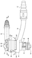
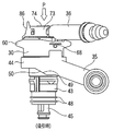
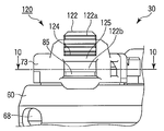
- FIG. 1 is a perspective view showing an endoscope according to an embodiment of the present invention.
- FIG. 2 is a side view of the fluid control device of the endoscope.
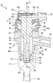
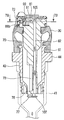
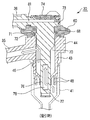
- FIG. 3 is a longitudinal sectional view showing the fluid control device in a longitudinal section along a plane (plane along line 3-3 in FIG. 5A) along the center of the intake and supply caps of the fluid control device.
- FIG. 4 is a longitudinal sectional view showing the fluid control device in a longitudinal section along a plane orthogonal to the centers of the intake and supply caps of the fluid control device (a surface along line 4-4 in FIG. 3).
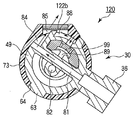
- FIG. 5A is a cross-sectional view of the fluid control device taken along a plane (a surface along the line 5A-5A in FIG.
- FIG. 5B is a longitudinal sectional view taken along line 5B-5B in FIG. 5A.
- FIG. 6A is a diagram showing a modification of the valve device.
- FIG. 6B is a diagram showing a modification of the valve device.
- FIG. 7A is a longitudinal cross-sectional view showing the fluid control device at the time of air supply, taken along a plane along line 4-4 in FIG.
- FIG. 7B is a horizontal and vertical cross-sectional view taken along line 7B-7B in FIG. 7A.
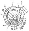
- FIG. 8A is a side view of the fluid control device during suction.
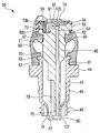
- FIG. 8B is a longitudinal sectional view showing the fluid control device at the time of suction along a plane along line 4-4 in FIG.
- FIG. 8C is a longitudinal cross-sectional view showing the fluid control device at the time of suction along a plane along line 3-3 in FIG.
- FIG. 9 is a front view of the barrier device that adjusts the amount of leakage from the air supply leak hole of the fluid control device.
- FIG. 10 is a cross-sectional view taken along a plane passing through the air supply leak hole (a plane along the line 10-10 in FIG. 9) to show the barrier device.
- FIG. 11 is a diagram illustrating a barrier device.
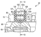
- FIG. 12 is a cross-sectional view taken along the center of the fluid control device to show the barrier device, and is a cross-sectional view taken along the line 12-12 in FIG.
- FIG. 13 is a front view of the air supply leak hole frame and the barrier body taken out.
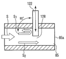
- FIG. 14A is an example in which a barrier body is provided, and is a diagram illustrating a relationship between the barrier body and an air flow.
- FIG. 14B is an example in which a barrier body is provided, and is a diagram illustrating a relationship between the barrier body and the air flow.
- FIG. 15 is a diagram schematically showing a general fluid control device.
- FIG. 16A is a diagram for explaining a phenomenon in which the sucked material flows backward from the channel into the air supply conduit during the suction operation in the fluid control device shown in FIG. 15.
- FIG. 16B is a diagram for explaining a phenomenon in which the sucked material flows backward from the channel into the air supply conduit during the suction operation in the fluid control device shown in FIG. 15.
- FIG. 16A is a diagram for explaining a phenomenon in which the sucked material flows backward from the channel into the air supply conduit during the suction operation in the fluid control device shown in FIG. 15.
- FIG. 16C is a diagram for explaining a phenomenon in which the sucked material flows backward from the channel into the air supply conduit during the suction operation in the fluid control device illustrated in FIG. 15.
- FIG. 16D is a diagram for explaining a phenomenon in which the sucked material flows backward from the channel into the air supply conduit during the suction operation in the fluid control device illustrated in FIG. 15.
- FIG. 16E is a diagram for explaining a phenomenon in which the sucked material flows backward from the channel into the air supply conduit during the suction operation in the fluid control device shown in FIG. 15.
- FIG. 16F is a diagram for explaining a phenomenon in which the sucked material flows backward from the channel into the air supply conduit during the suction operation in the fluid control device shown in FIG. 15.
- FIG. 16G is a diagram for explaining a phenomenon in which the sucked material flows backward from the channel into the air supply conduit during the suction operation in the fluid control device shown in FIG. 15.
- FIG. 1 is a perspective view showing an endoscope 10 of an endoscope apparatus according to an embodiment of the present invention.
- the endoscope 10 includes an elongated endoscope insertion portion 12 that is inserted into a body cavity, and an endoscope operation portion 14 that is coupled to the proximal end of the endoscope insertion portion 12.
- the endoscope insertion portion 12 is configured by connecting a distal end configuration portion 15, a bending portion 16 to be bent, and a long and flexible flexible tube portion 17 in order from the distal end side. Yes.
- the tip component 15 is provided with an illumination window and an imaging observation window (not shown). Thus, when the endoscope insertion portion 12 is inserted into the body cavity, the inside of the body cavity or the like is imaged and observed.
- the endoscope operation unit 14 includes an endoscope holding unit 22 that is held by an operator, and an endoscope operation unit main body 23 that is located on the proximal end side with respect to the endoscope holding unit 22.
- the endoscope operation section main body 23 is provided with a bending lever 24 for bending the bending section 16.
- a plurality of operation switches 18 for controlling imaging are provided at the proximal portion of the endoscope operation unit 14.
- a universal cord 19 that guides a light guide, a signal cable, and the like (not shown) from the endoscope apparatus side is connected to the endoscope operation unit 14.
- a bending drive mechanism (not shown) operated by the bending lever 24 is provided in the endoscope operation section main body 23 .
- This bending drive mechanism is operated by the bending lever 24 to bend the bending portion 16 by using an operation member such as an operation wire (not shown) inserted into the endoscope insertion portion 12.
- an insertion channel (pipe) 25 for inserting instruments such as a treatment instrument is formed in the interior from the distal end of the endoscope insertion section 12 to the endoscope operation section 14, an insertion channel (pipe) 25 for inserting instruments such as a treatment instrument is formed.
- the insertion channel 25 also serves as a conduit that performs both air supply and suction described later.
- the distal end of the insertion channel 25 is opened at the distal end constituting portion 15 to form a channel opening 26 for ejecting suction, air supply, and a treatment instrument.
- the insertion channel 25 is branched in the endoscope operation section 14 into a conduit 27 on the treatment instrument insertion port side and a conduit 28 on the endoscope fluid control device 30 side, which will be described later.
- the treatment instrument insertion port side conduit 27 is connected to a treatment instrument insertion port 29 for inserting a treatment instrument and the like.
- the conduit 28 on the fluid control device 30 side is connected to the mounting portion 32.
- An endoscope fluid control device 30 to be described later is detachably mounted on the mounting portion 32.
- FIG. 2 is a side view of the fluid control device 30.
- the fluid control device 30 is provided with a suction base (suction tube connection port) 35 and an air supply base (air supply tube connection port) 36.
- a suction tube 38 is connected to the suction base 35, and an air supply tube 39 is connected to the air supply base 36.
- the extending tip of the suction tube 38 is detachably connected to a suction device such as a suction pump (not shown).
- the suction tube 38 is a suction conduit that leads to the insertion channel 25 and the conduit 28 that are one conduit.
- the extending tip of the air supply tube 39 is detachably connected to an air supply device such as an air supply pump (not shown).
- the fluid control device 30 here is configured as a single valve device in which a suction control valve mechanism and an air supply control valve mechanism are integrated, and has a structure that can be attached to and detached from the endoscope 10. .
- the mounting portion 32 to which the fluid control device 30 is mounted has a circular mounting tube 41 disposed in the endoscope operation unit main body 23.
- the attachment tube 41 is fixed to the endoscope operation unit main body 23.
- the upper end portion of the attachment tube 41 faces the outer surface side of the endoscope operation unit main body 23 and opens toward the outside.
- An inner end (lower end) portion of the attachment tube 41 is disposed in the endoscope operation unit main body 23 and connected to the conduit 28.
- the fluid control device 30 includes a substantially circular cylinder 43 serving as a valve device main body, and a piston body 45 mounted inside the cylinder 43.
- the fluid control device 30 controls the suction with respect to the insertion channel 25 by pushing the piston body 45 with a finger.
- the cylinder 43 is attached to the mounting tube 41 so that the lower end of the cylinder 43 is detachably fitted (attached) to the mounting tube 41, and the upper end of the cylinder 43 is exposed to the outside of the mounting tube 41. Installed.
- a flange 44 that is thicker than the inner diameter of the attachment tube 41 is formed on the outer periphery of the upper end portion of the cylinder 43. The flange 44 comes into contact with the outer end surface of the mounting tube 41, so that the insertion mounting position of the cylinder 43 with respect to the mounting tube 41 is determined.
- engaging portions that engage with each other are provided on the inner peripheral wall surface of the mounting tube 41 and the outer peripheral wall surface of the cylinder 43 that is fitted into the mounting tube 41.
- This engaging portion is provided on the other of the convex portion 46 formed on one of the outer peripheral wall surface of the cylinder 43 and the inner peripheral wall surface of the mounting tube 41 and the outer peripheral wall surface of the cylinder 43 and the inner peripheral wall surface of the mounting tube 41.
- the attachment pipe 41 supports (holds) the cylinder 43 by engaging the convex portion 46 and the concave portion 47.
- the convex portion 46 and the concave portion 47 are provided so as to extend over the entire circumference around the axis of the attachment tube 41 or the cylinder 43.
- a sealing projection 48 for sealing the inner portion of the mounting tube 41 with respect to the outside is disposed on the outer periphery of the lower end portion of the cylinder 43.
- the sealing projection 48 extends around the axis of the cylinder 43 over the entire circumference.
- a ring-shaped packing (not shown) may be attached to the outer peripheral portion of the cylinder 43 fitted into the attachment pipe 41. Thereby, the fitting part of the attachment pipe 41 and the cylinder 43 is sealed so as to be further dense. In this way, the cylinder 43 is held airtight with respect to the attachment tube 41. Further, the cylinder 43 can rotate while maintaining a sealed state around its own central axis.
- the cylinder 43 is fixedly held on the mounting tube 41 by the engaging force and the frictional force with respect to the mounting tube 41.
- a convex cam portion 49 protruding downward is formed on a part of the lower surface of the flange 44.
- the part of the lower surface of the flange 44 indicates a part located on the lower side of the suction cap 35, for example.
- a cam receiving portion 50 is formed at the edge of the upper end portion of the mounting tube 41 that is open.
- the cam receiving portion 50 is an engaged portion that faces the cam portion 49 and engages with the cam portion 49 and has a concave shape.
- the cam portion 49 and the cam receiving portion 50 function as a cam mechanism that supports the removal when the cylinder 43 is removed from the attachment tube 41.
- the cylinder 43 When the fluid control device 30 is attached to the attachment tube 41, the cylinder 43 is fitted into the attachment tube 41 in a predetermined direction. Then, the cam portion 49 engages with the cam receiving portion 50, and the cylinder 43 is attached to the attachment pipe 41 at a predetermined position as shown in FIG.
- the cam portion 49 comes out of the cam receiving portion 50 and pulls up the cylinder 43 from the attachment tube 41. Therefore, the cylinder 43 can be easily removed from the attachment tube 41.
- the flange 44 is formed with a suction cap 35 integrally with the cylinder 43 in a substantially tubular shape.
- the suction cap 35 protrudes toward one side of the cylinder 43.
- a suction tube connecting portion 57 for connecting the suction tube 38 is provided at the distal end portion of the suction base 35.
- a suction path 58 as a first pipe line is formed in the cylinder 43 and in the inner hole of the suction cap 35. That is, the cylinder 43 has a first pipe line (suction path 58) for transferring fluid to the insertion channel 25.
- the upper end of the cylinder 43 engages with the lower end of the elastic member 60.
- a circular connection portion 59 having a smaller diameter than the flange 44 is formed at the upper end portion of the cylinder 43.
- a recess 61 is formed on the outer periphery of the connecting portion 59 so as to extend over the entire circumference of the cylinder 43.
- the elastic member 60 is formed in a substantially cylindrical shape with elastic rubber or the like.
- a convex portion 62 is formed extending over the entire circumference around the axis of the elastic member 60. The convex portion 62 is fitted into the concave portion 61.
- the opening part in the lower end part of the elastic member 60 is fitted on the outer periphery of the connection part 59, and the elastic member 60 is airtightly connected to the cylinder 43.
- the lower end portion of the elastic member 60 is fitted to the upper end portion of the cylinder 43 in a sealed state in close contact with the cylinder 43, and the lower end portion of the elastic member 60 is fixedly attached to the cylinder 43 in a sealed state.
- the lower end portion of the elastic member 60 is mounted coaxially with the cylinder 43 at the upper end portion of the cylinder 43.
- the elastic member 60 is formed in a substantially cylindrical shape.
- the central portion of the upper end portion of the elastic member 60 is open.
- a piston body 45 attached to the cylinder 43 is inserted through the elastic member 60 so as to penetrate upward.
- a convex portion 66 is formed on the inner peripheral surface of the upper end portion of the elastic member 60.
- the convex portion 66 projects inward over the entire circumference around the axis of the elastic member 60.
- a recess 67 is formed on the outer periphery of the upper end portion of the piston body 45. The recess 67 extends around the entire circumference of the cylinder 43.
- the side wall portion of the middle portion of the elastic member 60 is folded so as to protrude outward, and is a spring member that can be elastically compressed and deformed in the axial direction.
- a suction leak hole 68 communicating with the inside of the cylinder 43 (the suction path 58 as the first pipe line) is formed in the middle side wall of the elastic member 60.
- the suction leak hole 68 communicates with the suction path 58 and takes air into the cylinder 43 from the outside.
- a plurality of, for example, two suction leak holes 68 are arranged symmetrically with respect to the center of the elastic member 60. As shown in FIG.
- the one suction leak hole 68 is disposed between the suction base 35 and the air supply base 36 and at the same side portion as the suction base 35 and the air supply base 36.
- the suction leak hole 68 is substantially closed.
- the lower end part of the elastic member 60 has a cylindrical shape, and the central part of the lower end part is open. The lower end portion is fitted with the upper end portion of the cylinder 43.
- the elastic member 60 also has a cylindrical shape, and the central portion of the upper end is open. The outer periphery of the piston body 45 is fitted into this opening portion.
- a seal surface 71 is provided around the axis along the periphery of the opening portion on the inner surface of the upper end wall portion adjacent to the opening portion. It is formed so as to go around.
- the seal surface 71 has a taper shape protruding downward in the axial direction and inclined inward in the radial direction.
- an edge portion 72 is formed on the inner surface adjacent to the opening portion in the opening portion at the center portion of the lower end portion of the elastic member 60. The edge portion 72 protrudes around the axis along the periphery of the opening portion.
- the seal surface 71 comes into contact with the edge portion 72.
- the seal surface 71 and the edge portion 72 block communication between the inside of the cylinder 43 (the suction path 58 as the first pipe line) and the outside of the elastic member 60 (the suction leak hole 68).
- the seal surface 71 and the edge portion 72 function as a valve that is closed during a suction operation.
- the elastic member 60 holds the piston body 45 movably with respect to the cylinder 43 between a position where the suction path 58 is closed and a position where the suction path 58 is opened.
- the piston body 45 is formed of a substantially columnar member.
- the piston body 45 is disposed so as to substantially penetrate through both the elastic member 60 and the cylinder 43.
- the upper end portion of the piston body 45 is disposed so as to protrude upward from the opening portion of the central portion of the upper end portion of the elastic member 60.
- a cover member 73 covering the side periphery of the upper end portion of the piston body 45 is provided on the upper end portion of the piston body 45 protruding from the upper end portion of the elastic member 60.
- the center of the cover member 73 is opened, and the upper end surface of the piston body 45 corresponding to the opening portion is covered with an operation button (operation body) 74.
- the operation button 74 is a separate body from the cover member 73 and is a suction operation unit.
- the operation button 74 is formed in a film shape by a substantially disc-shaped elastic member.
- This elastic member is an elastic material such as rubber or thermoplastic resin.
- a convex portion 75 a extending over the entire circumference is formed on the upper surface of the outer peripheral edge of the operation button 74.
- a concave portion 75b extends over the entire periphery of the lower surface of the inner peripheral edge of the cover member 73.
- the convex portion 75a meshes with the concave portion 75b from below, and the cover member 73 and the operation button 74 are connected in an airtight manner.
- the mating portion between the cover member 73 and the operation button 74 may be bonded and fixed.
- the cover member 73 is disposed on the piston body 45. Therefore, the operation button 74 is disposed via the cover member 73 on the piston body 45 that is an insertion member through which the second divided air supply path 82 is inserted.
- the piston body 45 is movable in the axial direction with respect to the cylinder 43 while receiving the elastic force of the elastic member 60 by pressing or releasing the operation button 74.
- the elastic member 60 has elastic compression and elastic return biasing force as the piston body 45 moves, and deforms following the movement of the piston body 45. That is, as shown in FIG. 3, in a non-operating state in which the operation button 74 is not operated, the suction leak hole 68 is opened (this position is also referred to as a leak position). Further, as shown in FIGS. 8A, 8B, and 8C, when the operation button 74 is pushed in and the elastic member 60 is compressed, the suction leak hole 68 is substantially crushed, and the seal surface 71 and the edge portion 72 are compressed. Are in contact with each other and block between them (this position is also referred to as a suction position).
- the piston body 45 has a large diameter portion 45a at the upper end side portion and a small diameter portion 45b at the lower end side portion.
- the large diameter portion 45 a is generally disposed outside the cylinder 43.
- the outer diameter of the large-diameter portion 45 a is smaller than the diameter of the opening portion at the central portion of the lower end portion of the elastic member 60. Therefore, a gap is formed between the large diameter portion 45 a and the lower end portion of the elastic member 60. Therefore, as shown in FIG.
- the lower end portion of the piston body 45 is provided with a valve body 77 that cooperates with a valve seat 76 formed at the lower end portion of the cylinder 43.
- the valve seat 76 and the valve body 77 form a valve portion that is closed when not sucked.
- the lower end portion of the cylinder 43 has a tapered shape that is slightly inclined axially downward and radially inward from the inner peripheral surface, and has a small diameter cylindrical shape concentrically with the cylinder 43 in this tapered portion.
- the valve seat 76 is formed on this cylindrical inner surface. As shown in FIG.
- valve body 77 when the piston body 45 is in the non-operation position (leak position), the valve body 77 is disposed inside the valve seat 76, seals the inner hole of the valve seat 76, and Together with the seat 76, the inside of the mounting pipe 41 and the inside of the cylinder 43 (the suction path 58 as the first pipe line) are blocked. That is, the suction path 58 is closed.
- the piston body 45 is a valve portion that can move with respect to the cylinder 43 between a position where the suction path 58 is opened with respect to the insertion channel 25 and a position where the suction path 58 is closed with respect to the insertion channel 25. It has a valve body 77).
- a concave groove-shaped introduction portion 78 is formed on the side wall of the piston body 45 located above the valve body 77.
- the introduction part 78 extends from the upper end of the valve body 77 in the axial direction of the piston body 45.
- all the introduction portions 78 are disposed inside the cylinder 43.
- FIGS. 8A, 8B, and 8C when the piston body 45 is pushed in and is in the suction position, the introduction portion 78 is disposed across the entire valve seat 76 from the lower side to the upper side of the valve seat 76, and attached.
- the inside of the pipe 41 is communicated with the inside of the cylinder 43 (the suction path 58 as the first pipe line), and a suction force is applied to the pipe line 28. That is, the introduction part 78 communicates the inside of the attachment pipe 41 and the inside of the cylinder 43 (the suction path 58 as the first pipe line).
- the valve body 77 constitutes a valve portion that cooperates with the valve seat 76 to open and close the suction path 58 as the first pipe line in accordance with the movement position of the piston body 45.
- a regulating portion 80 is formed on the outer peripheral surface of the lower end portion of the piston body 45.
- the restricting portion 80 abuts on a restricting surface 79 that is a lower end surface of the valve seat 76 and restricts the upward movement of the piston body 45.
- Such a restricting portion 80 is a large-diameter portion protruding in the radial direction at the lower end portion of the piston body 45.
- the restriction portion 80 abuts on the restriction surface 79 to restrict the upward movement of the piston body 45. It has become.
- a first divided air supply path 81 that communicates with the inner hole of the air supply base 36 is provided across the upper end of the piston body 45.
- the piston body 45 is provided with a second divided air supply passage 82 so as to penetrate along the vertical axis direction of the piston body 45.
- the piston body 45 is an insertion member through which the second divided air supply path 82 is inserted.
- the first divided air supply path 81 and the second divided air supply path 82 are provided in the piston body 45 so as not to intersect with each other.
- the first divided air supply path 81 and the second divided air supply path 82 form a second pipe that leads to the air supply cap 36 that connects the air supply tube 39. That is, the piston body 45 includes a first divided air supply path 81 and a second divided air supply path 82 which are second pipes for transferring fluid from the connection port portion (air supply base 36) to the insertion channel 25. have. Further, the piston body 45 has a connection port portion (air supply base 36) for connecting a fluid tube (air supply tube 39).
- the first divided air supply path 81 communicates linearly with the inner hole of the air supply base 36.
- a first passage 84 is formed on the side wall surface of the upper end portion of the piston body 45.
- the first passage 84 is a groove-shaped notch (opening) along the circumferential direction of the piston body 45 covered with the cover member 73.
- the first divided air supply path 81 crosses the upper end portion of the piston body 45 and is connected to the first passage 84.
- the first passage 84 is covered by the cover member 73 and is formed along the circumferential direction of the piston body 45 in this state.
- path 84 is opened toward the air supply leak hole 85 mentioned later.
- the direction of the opening of the first passage 84 is arranged so as to protrude outward toward the air supply leak hole 85. Therefore, the resistance of the air flow leaking from the air supply leak hole 85 is reduced, and the air supply leak performance is improved.
- the cover member 73 is made of an elastic material such as rubber or thermoplastic resin.
- the cover member 73 has an annular portion 73 a that covers the periphery of the upper surface of the piston body 45, and an annular portion 73 b that covers the upper end of the side surface of the piston body 45.
- the annular portions 73 a and 73 b are attached so as to be tightly fitted around the upper end portion of the piston body 45.
- a protrusion 63 is provided on the side surface of the upper end portion of the piston body 45.
- the cover member 73 is provided with a hole 64 corresponding to the protrusion 63. By fitting the protrusion 63 into the hole 64, the cover member 73 is fixedly attached so as to be in close contact with the piston body 45.
- a finger contact surface 86 is formed on a part of the periphery of the cover member 73.
- the finger contact surface 86 is provided with an air supply leak hole 85 for opening the first passage 84 to the outside.
- the finger contact surface 86 is formed so as to face the push-in axis direction of the piston body 45 so as to be easily operated, and is formed so as to face obliquely downward with respect to the push-in axis direction. This prevents the piston body 45 from being pushed by the pressing force when the finger is applied to the finger contact surface 86. Then, when the finger pad is placed on the finger contact surface 86 and the air supply leak hole 85 is closed, the gas leak from the first passage 84 is blocked. Further, the amount of gas leakage can be adjusted by the degree (ratio) of closing the air supply leak hole 85 with a finger.
- a second passage 88 communicating with the first passage 84 through the air supply leak hole 85 is formed at the upper end portion of the piston body 45.
- the second passage 88 is disposed on the opposite side of the first passage 84 with the air supply leak hole 85 interposed therebetween.
- the direction of the flow path from the first passage 84 toward the air supply leak hole 85 and the direction of the flow path from the air supply leak hole 85 to the second passage 88 intersect, and the direction of the flow is near the intersection of both directions.
- An air leak hole 85 is formed.
- the first passage 84 and the second passage 88 are formed so as to intersect and invert at the air supply leak hole 85.
- the direction of the flow path from the first passage 84 toward the air supply leak hole 85 is a direction that penetrates through the air supply leak hole 85 and goes outward, and the second passage 88 extends from the outside of the air supply leak hole 85 to the inside. It is formed to head toward.
- the barrier can be regarded as a mirror. In this case, the light from the first passage 84 toward the air supply leak hole 85 is reflected by the barrier, and the inflow end of the second passage 88 is positioned in the reflected direction. Is formed.
- first passage 84 and the second passage 88 are disposed on the opposite sides with the air supply leak hole 85 interposed therebetween so as to be inverted and bent by the air supply leak hole 85.
- the angle formed by the direction of the flow path from the first passage 84 toward the air supply leak hole 85 and the direction of the flow path from the air supply leak hole 85 toward the second passage 88 is approximately 90 °.
- the first passage 84 and the second passage 88 are disposed.
- the air supply leak hole 85 is located at this inversion point.
- the second passage 88 includes an upstream groove 88a formed on the outer surface of the upper end portion of the piston body 45, and a downstream hole 88b drilled in the upper end portion of the piston body 45. have.
- the downstream hole 88 b is continuous with a concave hole 89 formed so as to open to the outer surface of the upper end portion of the piston body 45.
- the hole 89 is formed so as to communicate with a third passage 91 formed between the upper end surface of the piston body 45 and the inner surface of the operation button 74.
- the third passage 91 communicates with the first passage 84 via the second passage 88 and the air supply leak hole 85, and communicates with the second divided air supply passage 82 as described later.
- the three passages 91 and the second divided air supply passage 82 are air supply conduits that lead to the insertion channel 25 and the conduit 28 that are one conduit.
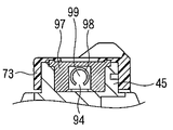
- a check valve 95 that is a first valve that prevents backflow of air supply is provided between the second passage 88 and the third passage 91. That is, the check valve 95, which is the first valve, is provided in the above-described air supply conduit and opens only when air is supplied.
- the check valve 95 is formed by making a valve seat 96 formed on the wall surface of the hole 89 located on the second passage 88 side, an elastic member 97 fitted in the hole 89, and making a cut 98 in the elastic member 97. And a valve body 99. As shown in FIG.
- the notch 98 is cut into an arc shape or a C shape while leaving a part of the elastic member 97 serving as the hinge portion 94, and the valve body 99 is formed in a flap shape.
- the elastic member 97 is fitted into a hole 89 drilled from the upper end surface of the piston body 45.
- the valve seat 96 is located on the upstream side of the air flow and is disposed so as to face the valve body 99 located on the downstream side, and is installed in a state in which the valve body 99 is elastically pressed against the valve seat 96. Therefore, the check valve 95 does not prevent the forward air flow, but only prevents the reverse flow.
- the valve body 99 has a substantially C-shape.
- the surface area of the valve body 99 is larger than the surface area of the notch 98.
- the hinge portion 94 that supports the valve body 99 is positioned in the direction in which the piston body 45 is pushed, that is, the lower side of the valve body 99. Therefore, even when a force that pushes down the piston body 45 is applied to the elastic member 97 and the elastic member 97 is deformed when the piston body 45 is pushed in, the influence of the pushing down force or the deformation of the elastic member 97 is influenced by the hinge portion 94. 99 is difficult to reach. Further, the pressing force applied to the elastic member 97 is temporarily received at the bottom surface of the hole 89 and thus blocked, and is hardly transmitted to the valve body 99. Therefore, the operation of pushing the piston body 45 stabilizes the opening / closing operation of the valve body 99 without the valve body 99 being crushed or twisted.
- the check valve 95 which is the first valve, includes a first divided air supply path 81, a first passage 84, and an air supply leak hole that are air supply pipes.
- segmentation air supply path 82 it arrange
- the valve body 99 is disposed on a piston body 45 that is an insertion member.
- the upper end surface of the piston body 45 is covered with a cover member 73 and an operation button (operation body) 74 in an airtight state with respect to the outside.
- an operation button (operation body) 74 when the operation button 74 is not pushed in, the gap between the inner surface of the operation button 74 and the upper end surface of the piston body 45 is shown in FIG.
- the third passage 91 is secured.
- the third passage 91 communicates with the second divided air supply path 82 having one end opened at the upper end portion of the piston body 45.
- a second valve capable of blocking the third passage 91 and the second divided air supply passage 82 is provided between the operation button 74 and the piston body 45 when performing a suction operation.
- a valve device is provided. That is, as shown in FIG. 4, the operation button 74 has a convex valve body 105 facing the second divided air supply path 82. The valve body portion 105 that is a valve device protrudes from the inner surface of the operation button 74. The valve body 105 is separated from the second divided air supply path 82 in a normal state where the operation button 74 is not pushed in and operated.
- the valve body 105 When the operation button 74 is pushed during the suction operation, the valve body 105 abuts on the second divided air supply path 82 and closes the second divided air supply path 82.
- the operation button 74 may block the second divided air supply path 82 directly by the inner surface of the operation button 74 instead of the valve body portion 105. That is, the operation button 74 may also serve as a valve body (valve device).
- the suction operation is performed as described above, when the operation button 74 is pushed, the inner surface of the operation button 74 or the valve body portion 105 closes the second divided air supply path 82.
- the valve device (the valve body 105 and the operation button 74) as the second valve is disposed on the operation button 74, and the operation button 74 is inserted when the operation button 74 is operated to perform a suction operation.
- the air supply duct to be operated it functions as a backflow prevention valve that blocks communication between the first divided air supply path 81 that is one of the air supply ducts and the second divided air supply path 82 that is the other of the air supply ducts. It is like that.
- valve device which is the second valve is disposed on the piston body 45 which is the insertion member via the operation button 74.
- the valve body 99 and the valve body portion 105 are disposed on the piston body 45.
- the operation button 74 when the operation button 74 is on standby, a gap is formed between the inner surface of the operation button 74 and the upper end surface of the piston body 45 as described above.
- the inner surface of the operation button 74 may be in close contact with the upper end surface of the piston body 45 with a constant urging force by the elastic force of the operation button 74 itself. Even in this case, the operation button 74 is lifted by the air supply pressure, the third passage 91 is secured, and air can be supplied from the third passage 91 to the second divided air supply passage 82 side. .
- the air supply pressure is relatively decreased from the first divided air supply path 81 side during suction or when the air supply leak hole 85 is opened, the second divided air supply path 82 is moved by the operation button 74.
- the inner surface of the operation button 74 and the valve body portion 105 are closed, and have an advantage that the valve functions as a valve that blocks communication between the first divided air supply path 81 and the second divided air supply path 82. Have.
- the inner surface of the operation button 74 that is also a valve member and the valve body portion 105 are disposed in the piston body 45, and the first divided air supply path 81 and the second divided air supply path 82 communicate with each other. Cut off.
- valve body portion 105 serving as the second valve includes the first divided air supply path 81, the first passage 84, the air supply leak hole 85, the second passage 88, the third passage 91, and the second air supply conduit.
- the divided air supply passage 82 is disposed on the downstream side of the air supply with respect to the check valve 95 which is the first valve.
- the operation button 74 When the inner surface of the operation button 74 is brought into close contact with the upper end surface of the piston body 45 by the elastic force of the operation button 74 itself and air is supplied, the first divided air supply path 81 and the second divided air supply path 82 are used. Once communicated with each other, the pressure in the operation button 74 suddenly decreases, the operation button 74 contracts, the second divided air supply path 82 is once blocked by the operation button 74, and then the air supply again. When the air pressure increases, the operation button 74 is expanded and the second divided air supply path 82 is opened. When the expansion and contraction of the operation button 74 are repeated in this way, the operation button 74 vibrates and a sound is generated. This sound changes according to the air supply state such as the air supply amount and the air supply pressure. Therefore, the operator can grasp the air supply state which is difficult to grasp visually by sound.
- the second divided air supply path 82 penetrates the piston body 45 in the moving axis direction of the piston body 45 as shown in FIG.
- the lower end of the second divided air supply path 82 forms an air supply port 107 on the lower end surface of the piston body 45.
- the air supply port 107 is opened so as to always communicate with the inside of the attachment pipe 41.
- the air supply port 107 opens at a lower end portion of the piston body 45 so as to be orthogonal to the extending direction of the insertion channel 25. For this reason, it becomes difficult for the suctioned matter to enter the second divided air supply path 82 and the like.
- a suction tube connecting portion 57 for connecting a suction tube 38 is provided at the tip of the suction base 35.
- the fluid control device 30 is attached to the attachment portion 32 as a preparation.
- the cylinder 43 is inserted into the attachment pipe 41 so that the cam portion 49 and the cam receiving portion 50 are aligned.
- the fluid control device 30 is mounted on the mounting portion 32 so that the convex portion 46 and the concave portion 47 are engaged.
- the suction tube connecting portion 57 is connected to one end of the suction tube 38, and the other end of the suction tube 38 is connected to a suction device (not shown).
- the air supply cap 36 is connected to one end of an air supply tube 39, and the other end of the air supply tube 39 is connected to an air supply device (not shown).
- the fluid control device 30 is in a standby state.
- the suction path 58 and the suction leak passage 70 are connected to the suction leak hole 68, so that external air is taken into the fluid control device 30 from the suction leak hole 68.
- the valve portion composed of the valve seat 76 and the valve body 77 is in a closed state, and communication to the pipe line 28 (insertion channel 25) side is in a blocked state. Accordingly, suction from the insertion channel 25 side is prevented. 3, the air taken in from the suction leak hole 68 is sucked by the suction device through the suction cap 35 and the suction tube 38.
- the compressed air is sent to the air supply base 36 through the air supply tube 39 as shown by an arrow in FIG. 5A.
- the compressed air transferred to the air supply cap 36 flows from the first divided air supply path 81 to the air supply leak hole 85 through the first passage 84 and leaks from the air supply leak hole 85 to the outside. Since the air supply pressure in the air supply leak hole 85 decreases due to this leak, the compressed air is not supplied to the second passage 88 side. Thus, since the compressed air is not supplied to the second passage 88 side, the valve body 99 is not opened. Therefore, the compressed air is not supplied from the third passage 91 to the second divided air supply path 82. Therefore, no air is supplied to the insertion channel 25.
- the endoscope insertion unit 12 is normally gripped by one hand and the endoscope operation unit 14 is gripped by the other hand.
- the hand holding the endoscope operation unit 14 holds the endoscope holding unit 22 with three fingers excluding the thumb and index finger, operates the bending lever 24 with the thumb of this hand, and controls the fluid with the index finger of this hand.
- the apparatus 30 is operated. That is, the operation button 74 and the air supply leak hole 85 are operated by the index finger of the hand that holds and operates the endoscope operation unit 14.
- the fluid control device 30 controls air supply.
- the index finger's belly is applied to the finger contact surface 86 to close the air supply leak hole 85.
- the gas (compressed air) leaked to the outside through the air supply leak hole 85 is blocked, and the air supply pressure in the air supply leak hole 85 is increased.
- the gas is sent to the second passage 88 side as indicated by the arrows shown in FIG. 7B.
- the gas flowing into the second passage 88 side pushes open the valve body 99 as shown in FIG. 7A and is sent to the third passage 91 through the hole 89 shown in FIG. 7B.
- the operation button 74 is not pressed and is lifted by the pressure of the gas fed into the third passage 91 as shown in FIG. 7A to form the third passage 91.
- the gas is then supplied to the second divided air supply path 82 through the third passage 91.
- the gas sent into the second divided air supply path 82 flows from the air supply port 107 to the insertion channel 25 through the cylinder 43, the inside of the attachment pipe 41, and the pipe line 28.
- the gas then flows from the channel opening 26 into the body cavity.
- the operation button 74 is pushed in the direction indicated by the arrow P as shown in FIG. 8A.
- the piston body 45 moves downward (suction position) with respect to the elastic member 60 and the cylinder 43.
- the elastic member 60 is crushed and the seal surface 71 comes into contact with the edge portion 72.
- the seal surface 71 and the edge portion 72 block communication between the inside of the cylinder 43 (the suction path 58 as the first pipe line) and the outside of the elastic member 60 (the suction leak hole 68).
- the valve body portion 105 closes the second divided air supply path 82, so that the first divided air supply path 81 and the air supply leak hole 85 side from the second divided air supply path 82. Suction to the is prevented. At this time, the side wall portion (near the suction leak hole 68) in the middle of the elastic member 60 is folded so as to protrude outward. Therefore, the suction leak hole 68 itself is also crushed (see FIGS. 8A, 8B, and 8C).
- the suction leak hole 68 is blocked from communicating with the outside.
- the piston body 45 is pushed into the cylinder 43 by the operation button 74,
- the valve body 77 penetrates downward from the valve seat 76, the valve portion comprising the valve seat 76 and the valve body 77 is opened, and the inside of the cylinder 43 and the inside of the mounting pipe 41 are communicated.
- the introduction part 78 is arrange
- the suction cap 35 can suck the liquid or the like in the body cavity from the channel opening 26 through the insertion channel 25 and the conduit 28 in the direction of the arrow shown in FIGS. 8B and 8C.
- the flap 162 of the suction tube connecting portion 57 is opened and the suction path is opened.
- the operation button 74 is pressed, so that the valve body portion 105 presses against the second divided air supply path 82 and blocks the second divided air supply path 82.
- segmentation air supply path 82 are divided
- the suction object is taken into the first divided air supply path 81 side and enters the air supply base 36, or from the air supply leak hole 85. It is prevented that it is ejected or enters the air supply base 36.
- the valve body 99 is closed even when liquid or the like flows into the second divided air supply path 82 in a negative pressure state, so the air supply leak hole 85 side It is possible to prevent the suctioned material (liquid or the like) from entering into the clean air supply tube 39 and to prevent the suctioned material from entering the clean air supply tube 39 side region.
- the suctioned material even if the suctioned material enters the second divided air supply path 82, the suctioned material is taken into the first divided air supply path 81 side to enter the air supply base 36, or the air supply leak It is possible to prevent ejection from the hole 85 or intrusion into the air supply base 36.
- air supply and suction operations can be performed with one finger on the insertion channel 25. Further, in the present embodiment, air leakage and suction leakage are surely performed during non-operation, and interference and backflow between air feeding and suction can be prevented during each operation of air feeding and suction. .
- the introduction portion 78 is disposed so as to straddle the entire valve seat 76 from the lower side to the upper side of the valve seat 76, so that the inside of the mounting pipe 41 and the inside of the cylinder 43 (as the first pipe line)
- the suction path 58 communicates with each other, and a suction force can be applied to the pipe line 28.
- the suction force can be ensured without reducing the suction force toward the suction path 58 where suction is desired.
- the fluid control device 30 When the fluid control device 30 is made of a disposable product, after the endoscope 10 is used, the fluid control device 30 is removed from the attachment tube 41 and only the endoscope 10 side is cleaned. Accordingly, the interference between the air supply function and the suction function is prevented, the insertion channel 25 is easily cleaned, and the trouble of cleaning and disinfecting the ducts inside the endoscope can be improved.
- the valve device that blocks communication between the first divided air supply path 81 and the second divided air supply path 82 is limited to the valve body portion 105 and the inner surface of the operation button 74. There is no need, and for example, the configuration shown in FIG. 6A may be provided.
- the valve device has a sliding surface 112 having the inner surface of the air supply pipe line 111 as a valve seat, and a valve body 113 slidably contacting the sliding surface 112.
- the air supply duct 111 indicates, for example, a first divided air supply path 81 and a second divided air supply path 82.
- the air supply duct 111 is opened (the first divided air supply path 81 and the second divided air supply path 82 communicate with each other). . That is, the valve device opens and closes by movement of the valve body 113 with respect to the sliding surface 112.
- the check valve 95 of the fluid control device 30 described above includes the valve seat 96 and the valve body 99, but may be configured as shown in FIG. 6B, for example.
- the check valve 95 includes a sliding surface 112 having the inner surface of the air supply pipe 111 as a valve seat, and a valve body 113 that is in sliding contact with the sliding surface 112.
- the air supply conduit 111 indicates, for example, a second passage 88 and a third passage 91.
- either one of the valve device (the inner surface of the valve body portion 105 and the operation button 74) and the check valve 95 opens and closes according to the movement of the valve body 113 with respect to the sliding surface 112, and is an air supply line.
- the communication between the first divided air supply path 81 and the second divided air supply path 82 is blocked, or the communication between the second path 88 and the third path 91 is blocked, for example.
- the barrier device 120 for adjusting the amount of gas leaking from the air supply leak hole 85 will be described with reference to FIGS.
- the endoscope 10 and the fluid control device 30 other than the barrier device 120 may be the same as those described above.
- the barrier device 120 has a barrier body 122 that slides freely so as to open and close the air supply leak hole 85.
- the barrier body 122 adjusts the opening amount of the air supply leak hole 85.
- the air supply leak hole 85 is formed in a rectangular shape whose vertical width is narrower than the horizontal width as shown in FIG.
- the upper side portion of the peripheral edge 125 of the air supply leak hole 85 is greatly protruded upward from the center of the finger contact surface 86.
- a concave groove 124 that is partitioned from the air supply leak hole 85 is formed in the protruding portion.
- the groove portion 124 is formed as a groove having a width matching the left and right width of the air supply leak hole 85 and is open forward.
- the barrier body 122 includes an operation portion 122 a disposed in the groove portion 124 and a plate-shaped shielding portion 122 b that crosses the air supply leak hole 85.
- the shielding part 122b is disposed so as to protrude from the peripheral edge 125 to the air supply leak hole 85.
- a plurality of locking grooves 126 separated in the sliding direction of the barrier body 122 are provided on the left and right end surfaces of the operation portion 122a. Locking protrusions 127 that are elastically deformed with respect to the locking groove 126 and fit into the locking groove 126 are provided on the side wall of the groove portion 124.
- the protruding amount of the shielding part 122b protruding to the air supply leak hole 85 is adjusted.
- the opening amount (throttle amount) of the air supply leak hole 85 is adjusted according to the protrusion amount.
- the barrier body 122 can be removed from the groove portion 124, and the fluid control device 30 can be used in a state where the barrier body 122 is not positioned in the air supply leak hole 85.
- the locking groove 126 to be locked to the locking protrusion 127 is selected and the opening amount of the air supply leak hole 85 is adjusted, but the adjustment method of the opening amount of the air supply leak hole 85 is not limited to this.
- the adjustment method other moving and positioning means such as a slide type in which the locking projection 127 is locked to the locking groove 126 by a frictional force obtained by pressing with a spring can be adopted.
- the barrier body 122 is movable in the vertical direction in the air supply leak hole 85, it may be moved in the horizontal direction.
- the barrier body at the intersection of the air supply direction from the first passage 84 to the air supply leak hole 85 and the air supply direction from the air supply leak hole 85 to the second passage 88.
- An air supply leak hole 85 having 122 shielding part 122b is arranged. Therefore, the air flow from the first passage 84 to the shielding portion 122b is blocked by the shielding portion 122b, and is reversed to travel from the shielding portion 122b to the second passage 88. If the shielding part 122b is arrange
- FIG. 14A and 14B show an example in which a barrier body 122 is provided.
- FIG. 14A is an example in which the barrier body 122 is disposed on the air release surface 85 a of the air supply leak hole 85.
- the barrier body 122 is disposed at an angle of 90 ° with respect to the longitudinal cross section of the air supply direction in the first passage 84.
- the flow S directed from the first passage 84 toward the air supply leak hole 85 is divided into a component S1 that hits the barrier body 122 and reverses and flows to the second passage 88 side, and a component S2 that flows out without hitting the barrier body 122.
- the size of the slit 128 (atmospheric open space / atmospheric open surface 85a) varies depending on the slide position of the barrier 122, the component S1 flowing toward the second passage 88, which is the amount of air supplied to the second passage 88, is adjusted. The That is, the size of the slit 128 adjusts the amount of air supplied to the second passage 88.
- FIG. 14B is an example in which the barrier body 122 is provided in the air supply pipe line inside the air release surface 85a.
- the flow S directed from the first passage 84 toward the air supply leak hole 85 is divided into a component S1 that hits the barrier body 122 and reverses and flows to the second passage 88 side, and a component S2 that flows out without hitting the barrier body 122.
- the barrier device 120 adjusts the amount of air supplied by changing the size of the opening of the air supply leak hole 85 by adjusting the position of the barrier body 122 in the air supply leak hole 85. For example, when the size of the air supply leak hole 85 increases, the amount of air supplied from the air supply leak hole 85 increases, and the amount of air supplied to the second divided air supply path 82 of the piston body 45 is reduced. be able to. Further, if the size of the opening of the air supply leak hole 85 is reduced by the shielding portion 122b, the pipe resistance against the air supply leaking to the outside increases, and the amount of air supply leaking from the air supply leak hole 85 decreases. The amount of air supplied to the second divided air supply path 82 increases.
- the leak amount in the air supply leak hole 85 can be adjusted by the barrier device 120, even if the finger is removed from the air supply leak hole 85, it is possible to continuously supply air with a desired air supply amount. . Therefore, for example, when the hypopharynx or the esophageal entrance, which is a physiologically constricted portion, is observed, it is always necessary to supply air so that the body cavity is inflated. In this case, since it is necessary for the finger to block the air supply leak hole 85, in order to supply air to the body cavity, a hand may be taken for air supply, and other operations of the endoscope may not be performed. Occurs. However, when the air supply amount is adjusted by the barrier device 120 described above, such a fear is prevented.
- the required air supply amount differs between when the hypopharynx is observed and when the esophageal entrance is observed. Such a case can be dealt with without changing the pressure of the air supply pump. That is, when a relatively soft part of the mucous membrane such as the hypopharynx is observed in close proximity, air supply with a relatively low flow rate is necessary. Also, when the esophagus, stomach, and other lumens are inflated instantaneously, it is easier to observe by using a high flow rate air supply. Therefore, when the air supply leak hole 85 is blocked by a finger, the air supply operation of both the low flow rate and the high flow rate is possible by using the barrier device 120.
Landscapes
- Health & Medical Sciences (AREA)
- Life Sciences & Earth Sciences (AREA)
- Surgery (AREA)
- Nuclear Medicine, Radiotherapy & Molecular Imaging (AREA)
- Biomedical Technology (AREA)
- Optics & Photonics (AREA)
- Pathology (AREA)
- Radiology & Medical Imaging (AREA)
- Biophysics (AREA)
- Engineering & Computer Science (AREA)
- Physics & Mathematics (AREA)
- Heart & Thoracic Surgery (AREA)
- Medical Informatics (AREA)
- Molecular Biology (AREA)
- Animal Behavior & Ethology (AREA)
- General Health & Medical Sciences (AREA)
- Public Health (AREA)
- Veterinary Medicine (AREA)
- Endoscopes (AREA)
Abstract
内視鏡用流体制御装置(30)は、吸引と送気を行う一つの管路(25、28)を有する内視鏡(10)に設けられ、前記管路(25、28)に対する送気と吸引の制御を行う。内視鏡用流体制御装置(30)は、前記一つの管路(25、28)に通じる送気管路(39、81、84、85、88、91、82)と、前記一つの管路(25、28)に通じる吸引管路(38)と、前記送気管路(39、81、84、85、88、91、82)に設けられ、送気時のみに開く第1の弁(95)と、吸引動作を行う操作ボタン(74)に配設され、前記操作ボタン(74)が操作された際に、前記操作ボタン(74)を挿通する前記送気管路(81、84、85、88、91、82)において、前記送気管路の一方(81)と前記送気管路の他方(82)との連通を遮断する第2の弁(105)とを有する。
Description
本発明は、内視鏡における一つの管路を通じて送気と吸引とを行い、流体の流れを制御する流体制御装置に関する。
一般に、内視鏡は、体腔内に挿入される挿入部と、挿入部の基端に連結した操作部とを有している。内視鏡は、この挿入部内において、送気、送水または吸引のために流体が流れる管路(チャンネル)を有している。流体の移動は、操作部に配設された流体制御装置によって制御される(特許文献1~3参照)。
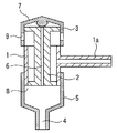
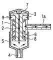
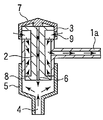
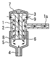
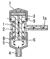
近年、送気と吸引とが内視鏡の一つの管路を通じて行われる。この場合、送気と吸引との切換え制御を、一つの弁装置により行う形態の流体制御装置が提案されている(特許文献4)。この弁装置は、図15に示す通りのものである。図15において、弁装置は、シリンダ1と、ピストン体2と、ピストン体2を突き出し位置に向けて付勢する弾性部材3とを有している。シリンダ1には、図示しない吸引チューブに通じる吸引管1aが設けられている。シリンダ1は、内視鏡のチャンネル4に連通した取付管5に取り付けられている。ピストン体2には、送気管路6が形成されている。この送気管路6の上端は、弾性を有する遮断膜7によって覆われ、閉塞されている。ピストン体2の下端には、ピストン体2とシリンダ1との間で形成される吸引弁8が設けられている。また、弾性部材3には、弾性部材3が押し潰されたときに閉じる吸引リーク孔9が形成されている。
そして、このような弁装置において、送気時には、送気管路6に通じる送気リーク孔(図示せず)が指で塞がれることにより、送気流が送気管路6を経てシリンダ1内からチャンネル4へ流れる。吸引時には、遮断膜7が押され、送気管路6の上端が遮断膜7により塞がれ、ピストン体2が弾性部材3の弾性力に抗してシリンダ1に押し込まれる。これにより、吸引リーク孔9が遮断膜7により閉じて、体腔内の液体がチャンネル4から吸引される。
特開平9-84756号公報
特開2003-52621号公報
特開平8-299265号公報
特開2009-18053号公報
流体制御装置は、内視鏡に設けられた1本のチャンネルにより、送気と吸引を行う。この流体制御装置は、送気時のみ開放する弁を有している。送気する方向と吸引する方向とは同じであり、弁は、吸引により開放し、送気管路内を吸引してしまう。そのため、本来、吸引したい内視鏡のチャンネル側への吸引力が落ちてしまうという虞が生じる。
特許文献4では、上記に対して、吸引操作する際に、遮断膜7が指で押されることで、遮断膜7が送気管路6の上端を遮断し、吸引力の低下を防ぐ構造が開示されている。
しかし、特許文献4に示された流体制御用弁装置では、吸引操作後、吸引物が、チャンネル4側から送気管路6内に逆流し、さらに遮断膜7を越えてしまう虞が生じる。この吸引物逆流現象を図16A乃至図16Gに従って説明する。
図16Aに示す吸引待機時において、吸引リーク孔9が開放しているので、外気は吸引リーク孔9からを吸引される。このとき、吸引弁8は閉じているので、チャンネル4側には吸引力が働かない。
次に、図16Bに示すように、チャンネル4から吸引が開始される場合、弾性部材3は指で押し潰され、ピストン体2は押し込まれ、吸引リーク孔9は遮断された状態になる。一方、吸引弁8は開いた状態になる。そして、ピストン体2の周囲領域を含むシリンダ1の内部は吸引管1aに通じているので、吸引管1aはシリンダ1の内部を介してチャンネル4に連通する。これにより吸引がチャンネル4から行われる。
次に、吸引がフルに行われると、図16Cに示すように、チャンネル4からシリンダ1内まで吸引力が行き渡り、送気管路6内も吸引された陰圧の状態になり、遮断膜7も吸引される状態にある。また、チャンネル4からシリンダ1及び送気管路6内は、吸引した液体で満たされる状態になる。
次に、指が遮断膜7から離され、吸引が解除される場合、最初の段階では、図16Dに示すように、吸引リーク孔9が開き始めるので、外気は、吸引リーク孔9からシリンダ1内に取り込まれ、吸引リーク孔9に近い吸引管1aから図示しない吸引チューブを通じて外部の吸引ポンプに吸引される。このとき、シリンダ1の底部領域は、吸引リーク孔9から取り込まれた外気により加圧され始める。チャンネル4内と送気管路6内とには、粘性を有する液体が存在する。このためチャンネル4内と送気管路6内とは、陰圧の液体で満たされた状態をしばらく持続する。
この吸引が解除される場合の次の段階において、図16Eに示すように、ピストン体2が上昇し、吸引弁8が閉じ、ピストン体2の周囲は吸引リーク状態の圧力に高まる。チャンネル4は細長く、チャンネル4の管路抵抗は比較的高いので、チャンネル4の内部と送気管路6の内部とには、陰圧状態の吸引物が残留したままである。そのためチャンネル4の内部と送気管路6の内部とには、陰圧が開放されない状態のままにある。したがって、チャンネル4内に残留していた液体等が、液体等の慣性で図16Fに示すようにシリンダ1内に流れ込む。また液体等が陰圧状態にある送気管路6の内部に引かれるようになる。この段階では、遮断膜7は指で押されていないので、図16Gに示すように、チャンネル4から送気管路6の内部に流れ込んだ液体等の吸引物は、流れ込む勢いで遮断膜7を押し上げる。そして吸引物は、遮断膜7の通路を通じて送気チューブ側へ逆流する現象を招く。
上記を避けるために、送気管路6の上端に押し当たる遮断膜7の付勢力が強くなれば、送気管路6の内部に流れ込む吸引物が遮断される。しかし、送気管路6を開放させるための送気圧力は高めなければならず、吸引物の逆流圧よりも高い送気圧を有する送気ポンプを用意する必要がある。また、遮断膜7の付勢力の調整が困難になる虞も生じる。
なお、ピストン体2を、ポンピングしてシリンダ1内を陰圧にすることもできるが、送気管路6内の陰圧が、それ以上に陰圧の場合、同様に吸引物は送気チューブ側へ逆流してしまう。
本発明は、上記課題に着目してなされたもので、吸引操作したとき、吸引した吸引物が、送気チューブ側の管路に流入してしまうことを防ぐことができるとともに、吸引をかけたい内視鏡の管路側への吸引力が落ちずに吸引力を確保できるようにした内視鏡用流体制御装置を提供する。
本発明の内視鏡用流体制御装置の一態様は、吸引と送気を行う一つの管路を有する内視鏡に設けられ、前記管路に対する送気と吸引の制御を行う内視鏡用流体制御装置において、前記一つの管路に通じる送気管路と、前記一つの管路に通じる吸引管路と、前記送気管路に設けられ、送気時のみに開く第1の弁と、吸引動作を行う操作ボタンに配設され、前記操作ボタンが操作された際に、前記操作ボタンを挿通する前記送気管路において、前記送気管路の一方と前記送気管路の他方との連通を遮断する第2の弁とを備える。
以下、本発明の実施形態について、詳細に説明する。
図1は、本発明の一実施形態に係る内視鏡装置の内視鏡10を示す斜視図である。この内視鏡10は、体腔内に挿入される細長い内視鏡挿入部12と、この内視鏡挿入部12の基端に連結された内視鏡操作部14とを有する。内視鏡挿入部12は、先端構成部15と、湾曲操作される湾曲部16と、長尺で可撓性の可撓管部17とを、先端側から順に連結することにより、構成されている。先端構成部15には、図示しない照明窓及び撮像用観察窓が設けられている。これにより内視鏡挿入部12が体腔に挿入されると、体腔等の内部が撮像して観察される。内視鏡操作部14は、操作者により把持される内視鏡把持部22と、この内視鏡把持部22より基端側に位置する内視鏡操作部本体23とを有している。内視鏡操作部本体23には、湾曲部16を湾曲操作するための湾曲レバー24が設けられている。内視鏡操作部14の手元部には、撮像を制御する複数の操作スイッチ18が設けられている。内視鏡操作部14には、内視鏡装置側からの図示しないライトガイドや信号ケーブル等を案内するユニバーサルコード19が接続されている。
内視鏡操作部本体23内には、湾曲レバー24により操作される湾曲駆動機構(図示せず)が設けられている。この湾曲駆動機構は、湾曲レバー24により操作されることで、内視鏡挿入部12内に挿通された図示しない操作ワイヤー等の操作部材を利用して湾曲部16を湾曲する。
内視鏡挿入部12の先端から内視鏡操作部14までの内部には、処置具等の器具を挿通するための挿通用チャンネル(管路)25が形成されている。挿通用チャンネル25は、後述する送気及び吸引の両方を行う管路を兼ねている。挿通用チャンネル25の先端は、先端構成部15にて開口し、吸引、送気及び処置具を突き出すためのチャンネル開口部26を形成している。挿通用チャンネル25は、内視鏡操作部14内において、処置具挿入口側の管路27と、後述する内視鏡用の流体制御装置30側の管路28とに分岐している。処置具挿入口側の管路27は、処置具等を挿入する処置具挿入口29と連結している。流体制御装置30側の管路28は、装着部32に連結している。装着部32には、後述する内視鏡用の流体制御装置30が着脱自在に装着する。
図2は、流体制御装置30の側面図である。この流体制御装置30には、吸引口金(吸引チューブ接続口部)35及び送気口金(送気チューブ接続口部)36が設けられている。図1に示すように、吸引口金35には吸引チューブ38が接続され、送気口金36には送気チューブ39が接続されている。吸引チューブ38の延出先端は、図示しない吸引ポンプ等の吸引装置に対し着脱自在に接続されるようになっている。吸引チューブ38は、一つの管路である挿通用チャンネル25と管路28とに通じる吸引管路である。送気チューブ39の延出先端は、図示しない送気ポンプ等の送気装置に対し着脱自在に接続されるようになっている。
次に、流体制御装置30について具体的に説明する。ここでの流体制御装置30は、吸引制御弁機構と送気制御弁機構とが一体的に組み込んだ単一の弁装置として構成され、内視鏡10に対して着脱可能な構造となっている。
図3に示すように、流体制御装置30が装着する装着部32は、内視鏡操作部本体23に配置されている円管状の取付管41を有している。取付管41は、内視鏡操作部本体23に固定されている。取付管41の上端部は、内視鏡操作部本体23の外表面側に面しており、外部に向けて開口している。取付管41の内方端(下端)部は、内視鏡操作部本体23内に配置され、管路28に接続する。
図3に示すように、流体制御装置30は、弁装置本体となる略円管状のシリンダ43と、シリンダ43の内部に装着されるピストン体45とを有している。流体制御装置30は、ピストン体45を指で押し込み操作することにより、挿通用チャンネル25に対する吸引を制御する。シリンダ43の下端部は取付管41に着脱自在に嵌め込まれ(取り付けられ)、シリンダ43の上端部は取付管41の外へ露出するように、シリンダ43は装着部32(取付管41)に対し装着される。詳細には、シリンダ43の上端部の外周には、取付管41の内径よりも太めのフランジ44が形成されている。このフランジ44が取付管41の外端面に当接することで、取付管41に対するシリンダ43の差し込み装着位置が定められる。
図3に示すように、取付管41の内周壁面と、取付管41に嵌め込まれるシリンダ43の外周壁面とには、互いに係合し合う係合部が設けられている。この係合部は、シリンダ43の外周壁面と取付管41の内周壁面とのいずれか一方に形成される凸部46と、シリンダ43の外周壁面と取付管41の内周壁面との他方に形成される凹部47とを有している。凸部46と凹部47とが係合することで、取付管41は、シリンダ43を支持(保持)する。凸部46と凹部47とは、取付管41またはシリンダ43の軸まわりの全周にわたって延びるように設けられている。シリンダ43の下端部の外周には、外部に対して取付管41の内方部を封止するシール用突起48が配設されている。シール用突起48は、シリンダ43の軸周りに全周にわたって延設されている。また、取付管41に嵌め込まれるシリンダ43の外周部分には、リング状パッキン(図示せず)が装着されてもよい。これにより、取付管41とシリンダ43との嵌合部間が、更に密になるようにシールされる。このようにして、シリンダ43は、取付管41に対して気密的に保持される。また、シリンダ43は、自身の中心軸を中心としてシール状態を維持して回転可能である。またシリンダ43は、取付管41に対する係合力及び摩擦力により取付管41に固定的に保持されている。
図3と図8Aとに示すように、フランジ44の下面の一部には、下方へ突き出す凸部形状のカム部49が形成されている。フランジ44の下面の一部とは、例えば吸引口金35の下側に位置した部分を示す。図3に示すように開口している取付管41の上端部の縁には、カム受け部50が形成されている。カム受け部50は、カム部49に対向し、カム部49と係合する被係合部であり、凹部形状である。カム部49とカム受け部50とは、取付管41からシリンダ43を取り外す際に抜去を支援するカム機構として機能する。流体制御装置30が取付管41に装着する場合、シリンダ43が取付管41に所定の向きで嵌め込まれる。すると、カム部49がカム受け部50に係合し、シリンダ43は図3に示すように取付管41に対して所定の位置で装着される。流体制御装置30が取付管41から取り外される場合、シリンダ43が軸周りに回転すると、カム部49は、カム受け部50から抜け出し、取付管41からシリンダ43を引き上げる。よってシリンダ43は、取付管41から容易に外すことができるようになっている。
図2及び図3に示すように、フランジ44には、吸引口金35がシリンダ43と一体に略円管状に形成されている。吸引口金35は、シリンダ43の一側方へ向けて突設されている。吸引口金35の先端部には、吸引チューブ38を接続するための吸引チューブ接続部57が設けられている。
また図3に示すように、シリンダ43の内部及び吸引口金35の内孔には、第1の管路としての吸引路58が形成されている。つまりシリンダ43は、挿通用チャンネル25に流体を移送する第1の管路(吸引路58)を有している。
図4に示すように、シリンダ43の上端部は、弾性部材60の下端部と係合する。詳細には、シリンダ43の上端部には、フランジ44より小径な円形の接続部59が形成されている。接続部59の外周には、シリンダ43の軸まわり全周にわたり延設した凹部61が形成されている。弾性部材60は、弾性を有するゴム等により略円筒状に形成されている。弾性部材60の下端部における内周面には、弾性部材60の軸まわり全周にわたり延設した凸部62が形成されている。そしてこの凸部62は、凹部61に嵌め込まれる。したがって、弾性部材60の下端部における開口部分は接続部59の外周に被嵌し、弾性部材60はシリンダ43に対して気密的に連結する。また弾性部材60の下端部はシリンダ43に密着するシール状態でシリンダ43の上端部に嵌合し、弾性部材60の下端部はシール状態でシリンダ43に対し固定的に取り付けられる。このときシリンダ43の上端部には、弾性部材60の下端部が、シリンダ43と同軸的に配置して装着される。
図3に示すように、弾性部材60は、略筒状に形成されている。弾性部材60の上端部の中央部は、開口している。弾性部材60には、シリンダ43に装着されたピストン体45が、上方へ突き抜けて挿通されている。弾性部材60の上端部の内周面には、凸部66が形成されている。凸部66は、弾性部材60の軸まわりの全周にわたり内方へ突き出て延設されている。またピストン体45の上端部の外周には、凹部67が形成されている。凹部67は、シリンダ43の軸まわり全周にわたり延設されている。凸部66が凹部67に密に嵌め込まれることにより、弾性部材60の上端部はピストン体45の上端部に密着するシール状態でピストン体45の上端部に嵌合し、弾性部材60の上端部はピストン体45に対し固定的に取り付けられている。
図8Aと図8Bと図8Cとに示すように、弾性部材60の中途部の側壁部分は、外側へ突き出すように折り畳まれ、軸方向に弾性的に圧縮変形が可能なバネ部材となっている。また、図3に示すように、弾性部材60の中途部の側壁部には、シリンダ43の内部(第1の管路としての吸引路58)と連通する吸引リーク孔68が穿設されている。吸引リーク孔68は、吸引路58に連通し、外部から空気をシリンダ43の内部に取り込む。ここでは、複数、例えば2つの吸引リーク孔68が弾性部材60の中心に対して対称的に配設されている。そして、一方の吸引リーク孔68は、図3に示すように、吸引口金35と送気口金36との間に、かつ吸引口金35と送気口金36と同じ側方部位に配設される。図8Aと図8Bと図8Cとに示すように、弾性部材60がピストン体45と一緒に押し込まれると、吸引リーク孔68を形成した中途部の側壁部が外側へ突き出すようにして折り畳まれ、吸引リーク孔68は略閉塞する。図3に示すように、弾性部材60の下端部は円筒状を有し、下端部の中央部分は開口している。下端部は、シリンダ43の上端部と嵌合する。また、上述したように弾性部材60も円筒状を有し、上端部の中央部分は開口している。この開口部分にはピストン体45の外周が嵌合する。
図3及び図4に示すように、弾性部材60の上端部の中央部分の開口部分において、この開口部分に隣接する上端壁部内面には、シール面71が開口部分の周縁に沿って軸周りに周回するように形成されている。シール面71は、軸方向下向きに突き出て、かつ径方向の内向きに傾斜するテーパ形状を有している。また弾性部材60の下端部の中央部分の開口部分において、この開口部分に隣接する内面には、エッジ部72が形成されている。エッジ部72は、開口部分の周縁に沿って軸周りに周回するように突き出ている。図8Aと図8Bと図8Cとに示すように、弾性部材60が圧縮すると、シール面71がエッジ部72に当接する。そしてシール面71とエッジ部72とはシリンダ43の内部(第1の管路としての吸引路58)と弾性部材60(吸引リーク孔68)の外部との連通を遮断する。このシール面71とエッジ部72とは、吸引操作時に閉塞する弁として機能する。
このように弾性部材60は、吸引路58を塞ぐ位置と吸引路58を開く位置との間でシリンダ43に対してピストン体45を移動自在に保持する。
図3に示すように、ピストン体45は、略円柱状の部材により形成されている。ピストン体45は、弾性部材60及びシリンダ43の両方にわたり、略貫通する状態で配設されている。ピストン体45の上端部は、弾性部材60の上端部の中央部分の開口部分から上方へ突き抜けて配置されている。弾性部材60の上端部から突き出たピストン体45の上端部には、ピストン体45の上端部の側周縁を覆うカバー部材73が覆設されている。カバー部材73の中央は開口し、この開口部分に対応するピストン体45の上端面は、操作ボタン(操作体)74によって覆われている。操作ボタン74は、カバー部材73と別体であり、吸引操作部である。操作ボタン74は、略円板状の弾性部材により膜状に形成されている。この弾性部材は、例えばゴム、熱可塑性樹脂等の弾性材料である。図3に示すように、操作ボタン74の外周縁上面には、全周にわたり延設した凸部75aが形成されている。カバー部材73の内周縁下面には、凹部75bが全周にわたり延設されている。凸部75aは凹部75bに下側から噛み合い、カバー部材73と操作ボタン74とは気密的に連結する。また、カバー部材73と操作ボタン74との合わせ部分を接着して固定するようにしてもよい。詳細については後述するが、カバー部材73は、ピストン体45に配設されている。よって操作ボタン74は、第2の分割送気路82が挿通する挿通部材であるピストン体45にカバー部材73を介して配設されることとなる。
ピストン体45は、操作ボタン74を押圧またはその押圧を解除することにより、弾性部材60の弾性力を受けながらシリンダ43に対し軸方向への移動可能である。また、弾性部材60は、ピストン体45の移動に伴い、弾性的な圧縮及び弾性的な復帰付勢力を有し、ピストン体45の移動に追従して変形する。つまり、図3に示すように、操作ボタン74が操作されない非操作状態では、吸引リーク孔68は開口している(この位置をリーク位置とも称する。)。また、図8Aと図8Bと図8Cとに示すように、操作ボタン74が押し込み操作され、弾性部材60が圧縮された場合、吸引リーク孔68は、略潰され、シール面71とエッジ部72が接触してその間を閉塞する(この位置を吸引位置とも称する。)。
ピストン体45は、図3に示すように、上端側部における太径部45aと、下端側部における細径部45bとを有している。ピストン体45が図3に示す非操作位置にある場合、太径部45aは、概略、シリンダ43の外側に配置される。太径部45aの外径は、弾性部材60の下端部の中央部分の開口部分の径よりも小さい。よって太径部45aと弾性部材60の下端部との間には、隙間が形成されている。したがって、図3に示すように、ピストン体45が非操作位置にある場合、太径部45aと、弾性部材60の下端部との間に形成される隙間には、シリンダ43の内部(第1の管路としての吸引路58)と吸引リーク孔68とを連通する吸引リーク用通路70が形成される。
また、図3に示すように、ピストン体45の下端部には、シリンダ43の下端部に形成した弁座76と協働する弁体77が設けられている。弁座76と弁体77とは、非吸引時に閉塞する弁部を形成している。シリンダ43の下端部は、内周面から軸方向下向きかつ径方向内向きにわずかに傾斜するテーパ形状を有し、このテーパ部分においてシリンダ43と同心的に小径の円筒状を有している。弁座76は、この円筒状の内面に形成されている。そして、図3に示すように、ピストン体45が非操作位置(リーク位置)にある場合、弁体77は、弁座76の内部に配置され、弁座76の内孔をシールするとともに、弁座76と共に取付管41の内部とシリンダ43の内部(第1の管路としての吸引路58)とを遮断している。つまり吸引路58は、閉じる。
図8Aと図8Bと図8Cとに示すように、ピストン体45が押し込まれ吸引位置にある場合は、弁体77は、弁座76の下方且つ取付管41の内部における位置を示す解放位置に配置される。このとき、取付管41の内部とシリンダ43の内部(第1の管路としての吸引路58)とは、連通する。つまり吸引路58は、開く。
つまりピストン体45は、挿通用チャンネル25に対して吸引路58を開く位置と、挿通用チャンネル25に対して吸引路58を塞ぐ位置との間で、シリンダ43に対して移動可能な弁部(弁体77)を有している。
図3及び図4に示すように、弁体77の上方に位置するピストン体45の側壁には、凹溝状の導入部78が形成されている。導入部78は、弁体77の上端からピストン体45の軸方向に延びている。図3に示すように、ピストン体45が非操作位置にある場合、すべての導入部78はシリンダ43の内部に配置される。図8Aと図8Bと図8Cとに示すように、ピストン体45が押し込まれ吸引位置にある場合、導入部78は、弁座76の下方から上方まで弁座76全体をまたいで配置され、取付管41の内部と、シリンダ43の内部(第1の管路としての吸引路58)とを連通し、管路28に吸引力を作用させる。つまり導入部78は、取付管41の内部とシリンダ43の内部(第1の管路としての吸引路58)とを連通するようになる。弁体77は、弁座76と協働してピストン体45の移動位置に応じて第1の管路としての吸引路58を開閉する弁部を構成する。
図3に示すように、ピストン体45の下端部の外周面には、規制部80が形成されている。規制部80は、弁座76の下端面からなる規制面79に当接し、ピストン体45の上方への移動を規制する。このような規制部80は、ピストン体45の下端部の径方向に突設された太径部である。そして図3に示すようにピストン体45が上方への移動を規制された非操作位置にある場合、規制部80は、規制面79に当接し、ピストン体45の上方への移動を規制するようになっている。ピストン体45が上方への移動を規制された非操作位置にある場合、弾性部材60は、軸方向に僅かに圧縮変形されるのみである。換言すれば、弾性部材60の付勢力によってピストン体45が上方へ移動する終端は、規制部80が規制面79に当接することによりピストン体45が上方への移動を規制される図3に示す位置となる。図3に示すようにピストン体45が非操作位置にある場合、吸引リーク孔68から吸引リーク用通路70を経て吸引口金35に通じる吸引リーク状態となる。また図8Aと図8Bと図8Cとに示すように、ピストン体45を押し込み操作した場合、吸引リーク用通路70が閉じ、吸引チューブ38が、吸引口金35と吸引路58と導入部78とを経て、取付管41及び管路28に通じる吸引状態となる。つまり弁座76と弁体77と規制面79と規制部80とは吸引制御機構を構成している。
次に、流体制御装置30の送気制御機構について説明する。図5Aに示すように、ピストン体45の上端部には、送気口金36の内孔に通じる第1の分割送気路81が横切るように設けられている。更に、ピストン体45には、図4と図5Aとに示すように第2の分割送気路82が、ピストン体45の上下軸方向に沿って貫通するように設けられている。ピストン体45は、第2の分割送気路82が挿通する挿通部材である。第1の分割送気路81と第2の分割送気路82とは、交差しないで互いに食い違う状態でピストン体45に設けられている。この第1の分割送気路81と第2の分割送気路82とは、送気チューブ39を接続する送気口金36に通じる第2の管路を形成する。つまりピストン体45は、接続口部(送気口金36)から挿通用チャンネル25に流体を移送する第2の管路である第1の分割送気路81と第2の分割送気路82とを有している。またピストン体45は、流体チューブ(送気チューブ39)を接続するための接続口部(送気口金36)を有している。
図5Aに示すように、第1の分割送気路81は、送気口金36の内孔に直線的に連通している。ピストン体45の上端部の側壁面には、第1通路84が形成されている。第1通路84は、カバー部材73で覆われるピストン体45の周方向に沿っている溝状の切り欠き(開口部)である。第1の分割送気路81は、ピストン体45の上端部を横切り、第1通路84に接続されている。第1通路84は、カバー部材73により覆われ、この状態でピストン体45の周方向に沿って形成されている。第1通路84は、後述する送気リーク孔85に向かって開口するようになっている。第1通路84の開口部の向きは、送気リーク孔85に向いて外へ突き抜けるように配置されている。そのため送気リーク孔85からリークする送気流の抵抗が小さくなり、送気リーク性能を高める。
図3と図4とに示すようにカバー部材73は、ゴム、熱可塑性樹脂等の弾性材料により形成されている。カバー部材73は、ピストン体45の上面周辺部を覆う環状部分73aと、ピストン体45の側面上端部を覆う環状部分73bとを有している。環状部分73a,73bは、ピストン体45の上端部の周辺部に密に被嵌して取り付けられている。また、図4及び図5Aに示すように、ピストン体45の上端部の側面には、突起63が設けられている。カバー部材73には、突起63に対応する孔64が設けられている。突起63が孔64に嵌め込まれることにより、カバー部材73はピストン体45に対し密着する状態で固定的に取り付けられている。
図5Aに示すように、カバー部材73の周縁の一部には、指当て面86が形成されている。指当て面86には、第1通路84を外部に開放するための送気リーク孔85が配設されている。指当て面86は、操作しやすくするためにピストン体45の押込み軸方向に向かいあうように形成され、かつ押込み軸方向に対して斜め下方に向くように形成されている。これにより、指当て面86に指を当てるときの押し当て力によってピストン体45を押込み操作することが回避されるようになる。そして、指当て面86に指の腹が当てられ、送気リーク孔85が閉じると、第1通路84からの気体のリークが遮断される。また、送気リーク孔85を指で塞ぐ度合い(割合)で気体のリーク量が調節できるようになる。
図5Aに示すように、ピストン体45の上端部には、送気リーク孔85を介して第1通路84と連通している第2通路88が形成されている。第2通路88は、送気リーク孔85を間に挟んで第1通路84の反対側に配置されている。また第1通路84から送気リーク孔85に向かう流路の方向と、送気リーク孔85から第2通路88に向かう流路の方向とは交差しており、両方向の交差部付近には送気リーク孔85が形成されている。第1通路84と第2通路88とは、送気リーク孔85で交差して反転する向きとなるように形成されている。したがって、第1通路84から送気リーク孔85に向かう流路の方向は、送気リーク孔85を通じてそのまま突き抜けて外へ向かう向きであり、第2通路88は送気リーク孔85の外から内方へ向かうように形成されている。送気リーク孔85が指等の障壁によって塞がれた場合、その障壁をいわばミラーに見立てることができる。この場合、第1通路84から送気リーク孔85へ向かう光が障壁に反射し、この反射した向きに第2通路88の流入端が位置するように、第1通路84と第2通路88とが形成されている。つまり、第1通路84と第2通路88とは、送気リーク孔85によって反転して屈曲するように、送気リーク孔85を介在させてそれぞれ反対側に配設されている。また、第1通路84から送気リーク孔85に向かう流路の方向と、送気リーク孔85から第2通路88側に向かう流路の方向とによって形成される角度が略90°となるように、第1通路84と第2通路88とは配置されている。送気リーク孔85は、この反転ポイントに位置する。
また、図5Aに示すように、第2通路88は、ピストン体45の上端部の外面に形成されている上流側の溝88aと、ピストン体45の上端部に穿孔した下流側の孔88bとを有している。下流側の孔88bは、ピストン体45の上端部の外面に開口するように形成した凹部状の孔89に連なっている。孔89は、図4に示すようにピストン体45の上端面と操作ボタン74の内面との間に形成される第3通路91に通じるように形成されている。そして、第3通路91は、第2通路88と送気リーク孔85とを介して第1通路84に連通し、後述するように第2の分割送気路82に連通する。
図3と図4と図5Aとに示すように、送気チューブ39と、第1の分割送気路81と、第1通路84と、送気リーク孔85と、第2通路88と、第3通路91と、第2の分割送気路82とは、一つの管路である挿通用チャンネル25と管路28とに通じる送気管路である。
図5Aと図5Bとに示すように、第2通路88と第3通路91の間には、送気の逆流を阻止する第1の弁である逆止弁95が設けられている。つまり第1の弁である逆止弁95は、上述した送気管路に設けられ、送気時のみに開く。この逆止弁95は、孔89の第2通路88側に位置する壁面に形成される弁座96と、孔89に嵌め込まれる弾性部材97と、弾性部材97に切込み98を入れることにより形成される弁体99とを有している。切込み98は、図5Bに示すように弾性部材97にヒンジ部94となる一部を残して円弧状またはC形状に切り込まれ、弁体99をフラップ状に形成している。弾性部材97は、ピストン体45の上端面から穿孔した孔89内に嵌め込まれる。弁座96は、送気流の上流側に位置し、下流側に位置する弁体99に向き合うように配置され、弁体99を弁座96に弾性的に押し当たる状態に設置している。したがって、この逆止弁95は、順方向の送気流を阻止せず、その逆流に対してのみ、その流れを阻止するようになる。
図5Bに示すように、弁体99は、略C字状を有している。弁体99の表面積は、切込み98の表面積よりも、大きい。逆止弁95に逆流する流れが生じたときに、切込み98に流れる管路抵抗よりも、弁体99に作用する流体圧力の方が大きく、弁体99は、フラップ状に動き、弁座96に当接する。したがって、この逆止弁95は、順方向の送気流を阻止せず、その逆流に対してのみ、その流れを阻止するようになる。
弁体99を支持するヒンジ部94は、ピストン体45を押し込む向き、つまり弁体99の下側に位置している。そのため、ピストン体45が押し込まれるとき、ピストン体45を押し下げる力が弾性部材97に加わり弾性部材97を変形させたとしても、この押し下げる力や弾性部材97の変形の影響はヒンジ部94によって弁体99に伝わり難い。また、弾性部材97に加わる押圧力は、孔89の底面で一旦、受け止められるため遮断され、弁体99に伝わり難い。したがって、ピストン体45を押し込む操作によって、弁体99が押し潰されたり捩じれたりせずに、弁体99の開閉動作を安定させる。
なお図3と図4と図5Aとに示すように、第1の弁である逆止弁95は、送気管路である第1の分割送気路81と第1通路84と送気リーク孔85と第2通路88と第3通路91と第2の分割送気路82とにおいて、第2の弁である弁体部105よりも送気の上流側に配置されている。これにより吸引した吸引物が、送気チューブ側の送気管路に流入してしまうことが防止される。
なお弁体99は、挿通部材であるピストン体45に配設されている。
図3に示すように、ピストン体45の上端面は、カバー部材73及び操作ボタン(操作体)74で外部に対して気密な状態で覆われている。そして、図3と図4とに示す操作ボタン74を押し込まない状態では、操作ボタン74の内面において、操作ボタン74の内面とピストン体45の上端面との間の隙間には、図4に示すように第3通路91が確保されている。第3通路91は、ピストン体45の上端部に一端を開口した第2の分割送気路82に連通する。
また図4に示すように、操作ボタン74とピストン体45との間には、吸引操作を行う場合において第3通路91と第2の分割送気路82とを遮断可能な第2の弁である弁装置が設けられている。すなわち、図4に示すように、操作ボタン74は、第2の分割送気路82に向き合う凸部状の弁体部105を有している。弁装置である弁体部105は、操作ボタン74の内面から突き出ている。弁体部105は、操作ボタン74を押し込み操作しない通常状態では、第2の分割送気路82から離れている。吸引操作時に操作ボタン74が押し込まれると、弁体部105は、第2の分割送気路82に当接し、第2の分割送気路82を閉塞する。操作ボタン74は、弁体部105ではなく、操作ボタン74の内面によって直接、第2の分割送気路82を閉塞してもよい。つまり操作ボタン74は、弁体部(弁装置)を兼ねていてもよい。このように吸引操作が行われる場合、操作ボタン74が押し込まれると、操作ボタン74の内面または弁体部105が第2の分割送気路82を塞ぐ。このように第2の弁である弁装置(弁体部105と操作ボタン74)は、操作ボタン74に配設され、操作ボタン74が操作され吸引動作が行われる際に、操作ボタン74を挿通する送気管路において、送気管路の一方である第1の分割送気路81と送気管路の他方である第2の分割送気路82との連通を遮断する逆流防止用弁として機能するようになっている。
また第2の弁である弁装置(弁体部105)は、操作ボタン74を介して挿通部材であるピストン体45に配設されている。そして上述したように弁体99と弁体部105とは、ピストン体45に配設されている。
ここでは、操作ボタン74の待機時、操作ボタン74の内面と、ピストン体45の上端面との間には、上述したように隙間が形成される。しかしながらピストン体45の上端面に、操作ボタン74の内面が操作ボタン74自身の弾性力によって一定の付勢力で密着してもよい。このようにした場合でも、送気圧力によって操作ボタン74が持ち上がり、第3通路91が確保されるようになり、第3通路91から第2の分割送気路82側へ送気は可能である。さらに、吸引時または送気リーク孔85を開放する場合等において、第1の分割送気路81側から送気圧力が相対的に低下すると、操作ボタン74によって第2の分割送気路82が閉塞され、操作ボタン74の内面と弁体部105とは、第1の分割送気路81と第2の分割送気路82との連通を遮断する弁としての機能を奏するようになる利点を有している。
このように、弁部材でもある操作ボタン74の内面と弁体部105とは、ピストン体45に配設され、第1の分割送気路81と第2の分割送気路82との連通を遮断する。
また第2の弁である弁体部105は、送気管路である第1の分割送気路81と第1通路84と送気リーク孔85と第2通路88と第3通路91と第2の分割送気路82とにおいて、第1の弁である逆止弁95よりも送気の下流側に配置されている。
なお、操作ボタン74の内面が操作ボタン74自身の弾性力によってピストン体45の上端面に密着し、送気が行われる場合、第1の分割送気路81と第2の分割送気路82とが一旦連通されると、操作ボタン74内の圧力が急激に低下し、操作ボタン74が収縮し、第2の分割送気路82は操作ボタン74によって一旦閉塞し、続いて、再び、送気圧力が上昇すると、操作ボタン74が膨張され、第2の分割送気路82は開放する。このように操作ボタン74の膨張及び収縮が繰り返されると、操作ボタン74が振動して、音が発生する。この音は、送気量、送気圧等の送気状態に応じて変化する。よって操作者は、目視により把握しにくい送気状態を、音により把握することが可能になる。
上述したように、第2の分割送気路82は、図4に示すようにピストン体45の移動軸方向にピストン体45を貫通している。第2の分割送気路82の下端は、図4に示すように、ピストン体45の下端面において送気口107を形成している。この送気口107は、取付管41の内部と常時、連通するように開口している。送気口107は、ピストン体45の下端部において挿通用チャンネル25の延長方向に直交して開口している。このため、吸引物が第2の分割送気路82に汚物等が浸入し難くなる。
図2に示すように、吸引口金35の先端部には、吸引チューブ38を接続するための吸引チューブ接続部57が設けられている。
次に、本実施形態に係る内視鏡装置の作用について説明する。この内視鏡10が使用される場合、準備として流体制御装置30が装着部32に装着される。このとき、図3に示すようにカム部49とカム受け部50とが位置を合わさるようにして、シリンダ43が取付管41に差し込まれる。また図3に示すように凸部46と凹部47とが係合するように、流体制御装置30が装着部32に装着される。次に吸引チューブ接続部57は吸引チューブ38の一端に接続され、吸引チューブ38の他端は図示しない吸引装置に接続される。また、送気口金36は送気チューブ39の一端に接続され、送気チューブ39の他端は図示しない送気装置に接続される。
このように流体制御装置30が装着部32に装着した際、図8Aに示すように送気リーク孔85を開口させた指当て面(送気操作面)86は、吸引チューブ38を接続した送気口金36と、吸引チューブ38を接続した吸引口金35とに対して異なる位置に位置する。また、指当て面(送気操作面)86は、吸引リーク孔68からも離れている。この結果、指当て面(送気操作面)86は、他の構成部材と極力干渉することがなく、送気リーク孔85を術者の手の指で容易に操作できるようになる。
次に、流体制御装置30の非操作状態について説明する。図3と図4と図5Aとに示すように、流体制御装置30は、待機状態にある。吸引装置が駆動すると、吸引路58及び吸引リーク用通路70は吸引リーク孔68に連なっているので、吸引リーク孔68から外部の空気が流体制御装置30に取り込まれる。このとき、弁座76と弁体77とからなる弁部は閉じた状態にあり、管路28(挿通用チャンネル25)側への連通は遮断状態にある。したがって、挿通用チャンネル25側から吸引されることが防止される。そして、図3に示す矢印のように、吸引リーク孔68から取り込まれた空気は、吸引口金35及び吸引チューブ38を通じて吸引装置によって吸引される。
また、送気装置が駆動すると、図5Aに示す矢印のように、送気チューブ39を通じて圧縮空気が送気口金36へと送り込まれる。送気口金36へと移送された圧縮空気は、第1の分割送気路81から第1通路84を通じて送気リーク孔85に流れ、送気リーク孔85から外部へリークする。このリークにより送気リーク孔85における送気圧は低下するので、圧縮空気は第2通路88側へ送気されない。このように圧縮空気は第2通路88側へ送気されないので、弁体99は開かない。よって圧縮空気は第3通路91から第2の分割送気路82へ送気されない。したがって、挿通用チャンネル25への送気もなされない状態にある。
次に、流体制御装置30により吸引と送気を制御する場合について説明する。内視鏡10が使用される際、通常、一方の手によって内視鏡挿入部12は把持され、他方の手によって内視鏡操作部14は把持される。内視鏡操作部14を把持する手は、親指及び人差指を除く三指によって内視鏡把持部22を把持し、この手の親指によって、湾曲レバー24を操作し、この手の人差指によって流体制御装置30を操作する。すなわち、操作ボタン74及び送気リーク孔85は、内視鏡操作部14を把持・操作する手の人差指により操作される。
まず、流体制御装置30が送気を制御する場合について説明する。図7Bに示すように人差指の腹は指当て面86に当て付けられ送気リーク孔85を閉じる。すると、送気リーク孔85を通じて外部にリークされていた気体(圧縮空気)が遮断され、送気リーク孔85内の送気圧が高まる。これにより図7Bに示す矢印のように、気体は第2通路88側へ送気される。第2通路88側へ流れ込んだ気体は、図7Aに示すように弁体99を押し開き、図7Bに示す孔89を通じて第3通路91に送気される。このとき、操作ボタン74は、押されておらず、図7Aに示すように第3通路91に送り込まれる気体の圧力によって浮き上がり、第3通路91を形成する。そして気体は、第3通路91を通じて第2の分割送気路82に送気される。第2の分割送気路82に送り込まれた気体は、送気口107から、シリンダ43と取付管41の内部と管路28とを通じて、挿通用チャンネル25へ流れる。そして、気体は、チャンネル開口部26から体腔内へ流れる。
次に、流体制御装置30が吸引を制御する場合について説明する。この場合は図8Aに示すように、矢印Pで示す向きに操作ボタン74が押し込まれる。これにより弾性部材60及びシリンダ43に対し、ピストン体45が下方(吸引位置)まで移動する。すると、図8Bと図8Cとに示すように、弾性部材60が押し潰され、シール面71がエッジ部72に当接する。これによりシール面71とエッジ部72とは、シリンダ43の内部(第1の管路としての吸引路58)と弾性部材60(吸引リーク孔68)の外部との連通を遮断する。また吸引操作中において、弁体部105が第2の分割送気路82を閉塞しているため、第2の分割送気路82から第1の分割送気路81及び送気リーク孔85側への吸引が防止される。このとき弾性部材60の中途部の側壁部(吸引リーク孔68付近)は、外向きに突出するように折り畳まれる。そのため吸引リーク孔68自身も押し潰された状態になる(図8Aと図8Bと図8Cとを参照)。
このようにして、吸引リーク孔68は外部に対する連通を遮断されると同時に、図8Bと図8Cとに示すように、ピストン体45は操作ボタン74に押されてシリンダ43の内部に押し込まれ、弁体77は弁座76よりも下方へ突き抜け、弁座76と弁体77とからなる弁部が開放し、シリンダ43の内部と取付管41の内部とが連通する。なお導入部78は、弁座76の下方から上方までまたいで配置されているために、シリンダ43の内部と取付管41の内部とを連通させる。したがって、シリンダ43と取付管41の内部とは、外部とは遮断した状態で連通する。よって、吸引口金35は、チャンネル開口部26から、挿通用チャンネル25と管路28とを通じて、体腔内の液体等を図8Bと図8Cとに示す矢印の向きに吸引することができる。この吸引時は、吸引チューブ接続部57のフラップ162は開き、吸引路を開放している。
吸引時、操作ボタン74が押圧されるので、弁体部105が第2の分割送気路82に押し当たり第2の分割送気路82を遮断する。これにより第1の分割送気路81と第2の分割送気路82とは、確実に分断される。この結果、送気リーク孔85が誤って閉塞されても、送気は行われない。また、吸引物が第2の分割送気路82に浸入しても、吸引物が第1の分割送気路81側に取り込まれ、送気口金36に浸入したり、送気リーク孔85から噴出したり、送気口金36に浸入されることが防止される。
指が操作ボタン74から離れ、吸引が解除される時、挿通用チャンネル25内に残留していた液体等が、液体等自身の慣性によってシリンダ1内に流れ込む。このとき本実施形態では、液体等が陰圧状態にある第2の分割送気路82の内部に流れ込むような場合であっても、弁体99を閉じているので、送気リーク孔85側への吸引物(液体等)の浸入を阻止でき、清浄な送気チューブ39側領域への吸引物の浸入を阻止できる。すなわち本実施形態では、吸引物が第2の分割送気路82に浸入しても、吸引物を第1の分割送気路81側に取り込んで送気口金36に浸入させたり、送気リーク孔85から噴出させたり、送気口金36に浸入させることを防止することができる。
また本実施形態では、挿通用チャンネル25に対して指一本の操作で送気と吸引の操作が可能である。更に本実施形態では、非操作時において、送気のリークと吸引のリークとが確実になされるとともに、送気と吸引のそれぞれの操作時には送気と吸引の干渉や逆流を防止することができる。
また本実施形態では、弁座76の下方から上方まで弁座76全体をまたぐように導入部78を配置することで、取付管41の内部と、シリンダ43の内部(第1の管路としての吸引路58)とを連通し、管路28に吸引力を作用させることができる。これにより本実施形態では、吸引をかけたい吸引路58側への吸引力を落とさずに吸引力を確保することができる。
本実施形態では、送気口金36が吸引チューブ38に誤って接続した場合には、送気リーク孔85より外部の気体が吸引される。このため、第1の分割送気路81から先への吸引が阻止されるようになる。さらに、送気リーク孔85が誤って閉塞してしまった場合にも、第1の分割送気路81側の圧力が低下することで、第2通路88の圧力が低下し、それにより弁体99が、弁座96に引っ張られ、操作ボタン74の内側の吸引を防止する。
流体制御装置30がディスポーザブル製品で構成された場合、内視鏡10が使用された後は、流体制御装置30が取付管41から取り外され、内視鏡10側のみを洗浄することになる。したがって、送気機能と吸引機能との干渉が防止され、挿通用チャンネル25は容易に洗浄され、内視鏡の内部の管路の洗浄・消毒の手間を改善することができる。
なお上述した流体制御装置30において、第1の分割送気路81と第2の分割送気路82との連通を遮断する弁装置は、弁体部105と操作ボタン74の内面とに限定する必要はなく、例えば、図6Aに示すような構成を有していても良い。弁装置は、送気管路111の内面を弁座とする摺動面112と、摺動面112に摺接する弁体113とを有している。送気管路111は、例えば第1の分割送気路81と第2の分割送気路82とを示す。弁体113が摺動面112を摺動し摺動面112から外れたとき、送気管路111が開放(第1の分割送気路81と第2の分割送気路82とが連通)する。つまり弁装置は、摺動面112に対する弁体113の移動により開閉する。
また、上述した流体制御装置30の逆止弁95は、弁座96と弁体99とを有しているが、例えば、図6Bに示すような構成でもよい。逆止弁95は、送気管路111の内面を弁座とする摺動面112と、この摺動面112に摺接する弁体113とを有している。送気管路111は、例えば第2通路88と第3通路91とを示す。弁体113が摺動面112上を一方へ移動して摺動面112から外れたとき、送気管路111が開放する。この場合、弁体113が他方へ移動するとき、弁体113は、ストッパ114に当たり、摺動面112から外れない遮断状態を維持する。つまり逆止弁95は、摺動面112に対する弁体113の移動により開閉する。
このように弁装置(弁体部105と操作ボタン74の内面)と逆止弁95とのいずれか一方は、摺動面112に対する弁体113の移動に応じて開閉し、送気管路である例えば第1の分割送気路81と第2の分割送気路82との連通を遮断し、または例えば第2通路88と第3通路91の連通を遮断する。
次に、図9乃至図13を参照して、送気リーク孔85からリークする気体のリーク量を調整する障壁装置120について説明する。ここで、障壁装置120以外の内視鏡10及び流体制御装置30等は上記説明のものと同様のものでよい。
図9に示すように障壁装置120は、送気リーク孔85を開閉するように自在にスライドする障壁体122を有している。障壁体122は、送気リーク孔85の開口量を調整する。
送気リーク孔85は、図11に示すように左右幅よりも上下幅が狭い矩形に形成されている。送気リーク孔85の周縁125の上辺部は、指当て面86の中央から上方へ偏って大きく張り出している。この張り出した部分には、送気リーク孔85から仕切られた凹状の溝部124が形成されている。溝部124は、送気リーク孔85の左右幅に合わせた幅の溝として形成され、前方へ開放している。
図13に示すように、障壁体122は、溝部124内に配置される操作部122aと、送気リーク孔85を横切る板状の遮蔽部122bとを有している。遮蔽部122bは、周縁125から送気リーク孔85に突き出るように配置されている。操作部122aの左右側端面には、障壁体122のスライド方向に離れた複数の係止溝126が設けられている。溝部124の側壁には、係止溝126に対して弾性的に変形し、係止溝126に嵌り込む係止突起127が設けられている。そして、係止突起127に係止する係止溝126が選ばれることにより、送気リーク孔85に突き出る遮蔽部122bの突出量が調整される。そしてこの突出量に応じて、送気リーク孔85の開口量(絞り量)が調整される。また、障壁体122は溝部124から取り外すことも可能であり、障壁体122が送気リーク孔85に位置しない状態で、流体制御装置30は使用可能である。また、係止突起127に係止する係止溝126が選ばれ、送気リーク孔85の開口量が調整されるが、送気リーク孔85の開口量の調整方式はこれに限定されない。調整方式は、ばねで押圧して得られる摩擦力で係止突起127を係止溝126に係止するスライド式のもの等、その他の移動及び位置決め手段を採用可能である。また、障壁体122は送気リーク孔85における上下方向へ移動可能としたが、左右方向へ移動してもよい。
また、図10に示すように、第1通路84から送気リーク孔85への送気方向と、送気リーク孔85から第2通路88への送気方向との交差部にて、障壁体122(遮蔽部122b)を有する送気リーク孔85が配置される。したがって、第1通路84から遮蔽部122bへの送気流は、遮蔽部122bによって遮られ、反転して遮蔽部122bから第2通路88へ向かう。遮蔽部122bが送気リーク孔85に配置されると、送気リーク孔85の開口量が少なくなり、リーク量が絞られる。
図14Aと図14Bとは、障壁体122を設ける例を示す。図14Aは、送気リーク孔85の大気開放面85aに障壁体122を配置する例である。障壁体122は、第1通路84での送気の流れ方向縦断面に対して90°の角度で配置されている。第1通路84から送気リーク孔85に向かう流れSは、障壁体122に当たり反転して第2通路88側へ流れる成分S1と、障壁体122に当たらずに外に流れ出す成分S2とに分かれる。スリット128(大気開放空間・大気開放面85a)の大きさは、障壁体122のスライド位置によって変わるため、第2通路88への送気量である第2通路88側へ流れる成分S1が調整される。つまりスリット128の大きさは、第2通路88への送気量を調整する。
図14Bは、大気開放面85aよりも内側であり、送気管路途中に障壁体122を設けた例である。第1通路84から送気リーク孔85に向かう流れSは、障壁体122に当たり反転して第2通路88側へ流れる成分S1と、障壁体122に当たらずに外に流れ出す成分S2とに分かれる。
以上のように障壁装置120は、送気リーク孔85における障壁体122の位置を調節することにより、送気リーク孔85の開口の大きさを変えて送気量を調節する。例えば、送気リーク孔85の開口の大きさが大きくなると、送気リーク孔85からリークする送気量が大きくなり、ピストン体45の第2の分割送気路82に送り込む送気量を絞ることができる。また、送気リーク孔85の開口の大きさが遮蔽部122bによって小さく絞られると、外へリークする送気流に対する管路抵抗が増し、送気リーク孔85からリークする送気量が少なくなり、第2の分割送気路82に送り込む送気量が多くなる。
そして、送気リーク孔85におけるリーク量は、障壁装置120により調整できるので、送気リーク孔85から指を離しても、好みの送気量で持続的に送気することができるようになる。したがって、例えば、生理的狭窄部である下咽頭や食道入口部等が観察される場合、体腔を膨らませておくように常に送気が必要である。この場合において、指が送気リーク孔85を塞ぐ必要があるため、体腔に送気を行うために、送気のために手がとられ、内視鏡の他の操作ができなくなってしまう虞が生じる。しかし上述した障壁装置120により送気量が調整されると、そのような虞が防止される。また、下咽頭が観察される場合と食道入口部が観察される場合とでは、必要とする送気量が相違する。このような場合にも、送気ポンプの圧力を変更せずに対応が可能である。つまり、下咽頭など比較的粘膜の柔らかい部位が近接して観察される場合には、比較的低流量の送気が必要である。また食道や胃などの管腔を瞬時に膨らます場合には、高流量の送気を用いたほうが観察し易い。そのため送気リーク孔85が指によって塞がれる場合には、障壁装置120が用いられることで、低流量と高流量との両方の送気操作が可能である。
以上、本発明の好ましい実施形態および変形例について説明してきたが、本発明は上述のものに限るものではない。また、それらを様々に組み合わせることも可能である。また、上述した実施形態では送気と吸引の流体の移送について説明したが、送気、吸引、送液等の流体移送に用いるようにしてもよい。
Claims (4)
- 吸引と送気を行う一つの管路(25、28)を有する内視鏡(10)に設けられ、前記管路(25、28)に対する送気と吸引の制御を行う内視鏡用流体制御装置(30)において、
前記一つの管路(25、28)に通じる送気管路(39、81、84、85、88、91、82)と、
前記一つの管路(25、28)に通じる吸引管路(38)と、
前記送気管路(39、81、84、85、88、91、82)に設けられ、送気時のみに開く第1の弁(95)と、
吸引動作を行う操作ボタン(74)に配設され、前記操作ボタン(74)が操作され吸引動作が行われる際に、前記操作ボタン(74)を挿通する前記送気管路(81、84、85、88、91、82)において、前記送気管路の一方(81)と前記送気管路の他方(82)との連通を遮断する第2の弁(105)と
を具備する内視鏡用流体制御装置(30)。 - 前記第1の弁(95)は、前記送気管路(39、81、84、85、88、91、82)において、前記第2の弁(105)よりも送気の上流側に配置されている請求項1に記載の内視鏡用流体制御装置(30)。
- 前記第1の弁(95)と前記第2の弁(105)との少なくとも一方は、弁体(113)と、前記弁体(113)が摺接する摺動面(112)とを有し、
前記一方は、前記摺動面(112)に対する前記弁体(113)の移動に応じて開閉する請求項2に記載の内視鏡用流体制御装置(30)。 - 前記第1の弁(95)は、第1の弁側弁座(96)と第1の弁側弁体(99)とを有し、
前記操作ボタン(74)は、前記送気管路の他方(82)が挿通する挿通部材(45)に配設され、
前記第1の弁側弁体(99)は前記挿通部材に配設され、前記第2の弁(105)は前記操作ボタン(74)を介して前記挿通部材(45)に配設され、
前記第1の弁側弁体(99)と前記第2の弁(105)とは、前記挿通部材(45)に配設されている請求項3に記載の内視鏡用流体制御装置(30)。
Priority Applications (4)
| Application Number | Priority Date | Filing Date | Title |
|---|---|---|---|
| EP09843069.7A EP2335552B1 (en) | 2009-03-30 | 2009-11-17 | Endoscopic fluid control apparatus |
| JP2010532135A JP4608606B2 (ja) | 2009-03-30 | 2009-11-17 | 内視鏡用流体制御装置 |
| CN200980133243XA CN102131451B (zh) | 2009-03-30 | 2009-11-17 | 内窥镜用流体控制装置 |
| US12/883,307 US8740776B2 (en) | 2009-03-30 | 2010-09-16 | Endoscopic fluid control apparatus |
Applications Claiming Priority (2)
| Application Number | Priority Date | Filing Date | Title |
|---|---|---|---|
| JP2009082917 | 2009-03-30 | ||
| JP2009-082917 | 2009-03-30 |
Related Child Applications (1)
| Application Number | Title | Priority Date | Filing Date |
|---|---|---|---|
| US12/883,307 Continuation US8740776B2 (en) | 2009-03-30 | 2010-09-16 | Endoscopic fluid control apparatus |
Publications (1)
| Publication Number | Publication Date |
|---|---|
| WO2010116563A1 true WO2010116563A1 (ja) | 2010-10-14 |
Family
ID=42935866
Family Applications (1)
| Application Number | Title | Priority Date | Filing Date |
|---|---|---|---|
| PCT/JP2009/069506 WO2010116563A1 (ja) | 2009-03-30 | 2009-11-17 | 内視鏡用流体制御装置 |
Country Status (5)
| Country | Link |
|---|---|
| US (1) | US8740776B2 (ja) |
| EP (1) | EP2335552B1 (ja) |
| JP (1) | JP4608606B2 (ja) |
| CN (1) | CN102131451B (ja) |
| WO (1) | WO2010116563A1 (ja) |
Cited By (3)
| Publication number | Priority date | Publication date | Assignee | Title |
|---|---|---|---|---|
| WO2015029496A1 (ja) * | 2013-08-27 | 2015-03-05 | オリンパスメディカルシステムズ株式会社 | 内視鏡用流体制御装置 |
| US9161680B2 (en) | 2013-11-26 | 2015-10-20 | Bracco Diagnostics Inc. | Disposable air/water valve for an endoscopic device |
| WO2020099441A1 (de) * | 2018-11-15 | 2020-05-22 | Olympus Winter & Ibe Gmbh | Medizinisches instrument für endoskopische anwendungen und einrichtung zum regulieren eines spülflüssigkeitsstroms für ein medizinisches instrument |
Families Citing this family (6)
| Publication number | Priority date | Publication date | Assignee | Title |
|---|---|---|---|---|
| WO2013099507A1 (ja) * | 2011-12-28 | 2013-07-04 | オリンパスメディカルシステムズ株式会社 | 体腔内圧調整装置及び内視鏡システム |
| CN106175655A (zh) * | 2016-09-28 | 2016-12-07 | 北京大学第医院 | 用于膀胱镜的灌注设备及膀胱镜系统 |
| WO2020162565A1 (ja) * | 2019-02-08 | 2020-08-13 | 富士フイルム株式会社 | 内視鏡の吸引制御装置及び内視鏡 |
| CN110251050A (zh) * | 2019-06-24 | 2019-09-20 | 珠海视新医用科技有限公司 | 一种吸引座以及包括该吸引座的内窥镜 |
| US20210378486A1 (en) * | 2020-06-05 | 2021-12-09 | Ga Health Company Limited | Suction valve for an endoscope |
| GB202110898D0 (en) * | 2021-07-29 | 2021-09-15 | Ga Health Medical Devices Limitied | A suction valve for an endoscope |
Citations (7)
| Publication number | Priority date | Publication date | Assignee | Title |
|---|---|---|---|---|
| JPH01120802U (ja) * | 1988-02-09 | 1989-08-16 | ||
| JPH08299265A (ja) | 1995-05-12 | 1996-11-19 | Olympus Optical Co Ltd | 内視鏡の吸引制御装置 |
| JPH0984756A (ja) | 1995-09-21 | 1997-03-31 | Olympus Optical Co Ltd | 内視鏡装置 |
| JP2003052621A (ja) | 2002-07-18 | 2003-02-25 | Olympus Optical Co Ltd | 内視鏡 |
| JP2003199706A (ja) * | 2003-01-08 | 2003-07-15 | Pentax Corp | 内視鏡の管路切換装置 |
| JP2004024561A (ja) * | 2002-06-26 | 2004-01-29 | Pentax Corp | 内視鏡の送気吸引操作機構 |
| JP2009018053A (ja) | 2007-07-12 | 2009-01-29 | Olympus Medical Systems Corp | 流体制御装置 |
Family Cites Families (7)
| Publication number | Priority date | Publication date | Assignee | Title |
|---|---|---|---|---|
| US4193406A (en) * | 1978-09-18 | 1980-03-18 | Jinotti Walter J | Dual purpose catheter |
| JPS57110226A (en) * | 1980-12-26 | 1982-07-09 | Olympus Optical Co | Air and liquid sending and sucking apparatus of endoscope |
| JP2556065B2 (ja) | 1987-11-04 | 1996-11-20 | 株式会社村田製作所 | 抵抗内蔵電子部品の製造方法 |
| US4852551A (en) * | 1988-04-22 | 1989-08-01 | Opielab, Inc. | Contamination-free endoscope valves for use with a disposable endoscope sheath |
| DE19731965A1 (de) * | 1997-07-24 | 1999-01-28 | Etm Endotech Gmbh Medizintechn | Luft/Wasser- und Absaugventile an Endoskopen |
| JP3488170B2 (ja) * | 2000-03-21 | 2004-01-19 | オリンパス株式会社 | 内視鏡 |
| JP2009521297A (ja) * | 2005-12-27 | 2009-06-04 | ストライカー ジーアイ リミテッド | 圧力解放機構を備えた内視鏡装置 |
-
2009
- 2009-11-17 CN CN200980133243XA patent/CN102131451B/zh active Active
- 2009-11-17 JP JP2010532135A patent/JP4608606B2/ja active Active
- 2009-11-17 EP EP09843069.7A patent/EP2335552B1/en not_active Not-in-force
- 2009-11-17 WO PCT/JP2009/069506 patent/WO2010116563A1/ja active Application Filing
-
2010
- 2010-09-16 US US12/883,307 patent/US8740776B2/en active Active
Patent Citations (7)
| Publication number | Priority date | Publication date | Assignee | Title |
|---|---|---|---|---|
| JPH01120802U (ja) * | 1988-02-09 | 1989-08-16 | ||
| JPH08299265A (ja) | 1995-05-12 | 1996-11-19 | Olympus Optical Co Ltd | 内視鏡の吸引制御装置 |
| JPH0984756A (ja) | 1995-09-21 | 1997-03-31 | Olympus Optical Co Ltd | 内視鏡装置 |
| JP2004024561A (ja) * | 2002-06-26 | 2004-01-29 | Pentax Corp | 内視鏡の送気吸引操作機構 |
| JP2003052621A (ja) | 2002-07-18 | 2003-02-25 | Olympus Optical Co Ltd | 内視鏡 |
| JP2003199706A (ja) * | 2003-01-08 | 2003-07-15 | Pentax Corp | 内視鏡の管路切換装置 |
| JP2009018053A (ja) | 2007-07-12 | 2009-01-29 | Olympus Medical Systems Corp | 流体制御装置 |
Non-Patent Citations (1)
| Title |
|---|
| See also references of EP2335552A4 * |
Cited By (5)
| Publication number | Priority date | Publication date | Assignee | Title |
|---|---|---|---|---|
| WO2015029496A1 (ja) * | 2013-08-27 | 2015-03-05 | オリンパスメディカルシステムズ株式会社 | 内視鏡用流体制御装置 |
| JP5722510B1 (ja) * | 2013-08-27 | 2015-05-20 | オリンパスメディカルシステムズ株式会社 | 内視鏡用流体制御装置 |
| US9615724B2 (en) | 2013-08-27 | 2017-04-11 | Olympus Corporation | Fluid control apparatus for endoscope |
| US9161680B2 (en) | 2013-11-26 | 2015-10-20 | Bracco Diagnostics Inc. | Disposable air/water valve for an endoscopic device |
| WO2020099441A1 (de) * | 2018-11-15 | 2020-05-22 | Olympus Winter & Ibe Gmbh | Medizinisches instrument für endoskopische anwendungen und einrichtung zum regulieren eines spülflüssigkeitsstroms für ein medizinisches instrument |
Also Published As
| Publication number | Publication date |
|---|---|
| CN102131451B (zh) | 2013-06-05 |
| EP2335552A1 (en) | 2011-06-22 |
| EP2335552B1 (en) | 2014-05-07 |
| US8740776B2 (en) | 2014-06-03 |
| EP2335552A4 (en) | 2011-08-31 |
| JP4608606B2 (ja) | 2011-01-12 |
| CN102131451A (zh) | 2011-07-20 |
| JPWO2010116563A1 (ja) | 2012-10-18 |
| US20110071357A1 (en) | 2011-03-24 |
Similar Documents
| Publication | Publication Date | Title |
|---|---|---|
| JP4608606B2 (ja) | 内視鏡用流体制御装置 | |
| JP5404569B2 (ja) | 内視鏡の吸引ボタン | |
| JP4841278B2 (ja) | 内視鏡の吸引装置 | |
| JP5349561B2 (ja) | 内視鏡用管路切換装置 | |
| JP5602712B2 (ja) | 内視鏡の吸引管路切り替え装置 | |
| JP5409570B2 (ja) | 内視鏡の吸引ボタン | |
| US9615724B2 (en) | Fluid control apparatus for endoscope | |
| JP5476361B2 (ja) | 内視鏡用管路切換装置及び超音波内視鏡 | |
| JP2021164491A (ja) | 内視鏡用流体制御装置 | |
| JP5036432B2 (ja) | 流体制御装置 | |
| JP4608605B2 (ja) | 内視鏡用流体制御装置 | |
| JP7119134B2 (ja) | 内視鏡の吸引制御装置及び内視鏡 | |
| CN112074224A (zh) | 内窥镜用流体控制装置 | |
| JP2006000525A (ja) | 超音波内視鏡の吸引操作弁装置 | |
| JP2012075473A (ja) | 内視鏡の吸引ボタン | |
| JP5460542B2 (ja) | 内視鏡の吸引ボタン | |
| JP5666027B2 (ja) | 内視鏡用管路切換装置及び超音波内視鏡 | |
| JP4512427B2 (ja) | 超音波内視鏡の吸引操作弁装置 | |
| JP5409569B2 (ja) | 内視鏡の吸引ボタン | |
| JP4217487B2 (ja) | 内視鏡の管路切換装置 | |
| JP2012071021A (ja) | 内視鏡の吸引ボタン | |
| JP2006081756A (ja) | 内視鏡の吸引制御装置 | |
| JP2001078957A (ja) | 内視鏡のバルブ構造 |
Legal Events
| Date | Code | Title | Description |
|---|---|---|---|
| WWE | Wipo information: entry into national phase |
Ref document number: 200980133243.X Country of ref document: CN |
|
| WWE | Wipo information: entry into national phase |
Ref document number: 2010532135 Country of ref document: JP |
|
| 121 | Ep: the epo has been informed by wipo that ep was designated in this application |
Ref document number: 09843069 Country of ref document: EP Kind code of ref document: A1 |
|
| WWE | Wipo information: entry into national phase |
Ref document number: 2009843069 Country of ref document: EP |
|
| NENP | Non-entry into the national phase |
Ref country code: DE |