WO2010109927A1 - 自動分析装置及び自動分析装置用分注ノズル - Google Patents
自動分析装置及び自動分析装置用分注ノズル Download PDFInfo
- Publication number
- WO2010109927A1 WO2010109927A1 PCT/JP2010/050017 JP2010050017W WO2010109927A1 WO 2010109927 A1 WO2010109927 A1 WO 2010109927A1 JP 2010050017 W JP2010050017 W JP 2010050017W WO 2010109927 A1 WO2010109927 A1 WO 2010109927A1
- Authority
- WO
- WIPO (PCT)
- Prior art keywords
- sample
- nozzle
- dispensing
- cell
- water
- Prior art date
- Legal status (The legal status is an assumption and is not a legal conclusion. Google has not performed a legal analysis and makes no representation as to the accuracy of the status listed.)
- Ceased
Links
Images




Classifications
-
- G—PHYSICS
- G01—MEASURING; TESTING
- G01N—INVESTIGATING OR ANALYSING MATERIALS BY DETERMINING THEIR CHEMICAL OR PHYSICAL PROPERTIES
- G01N35/00—Automatic analysis not limited to methods or materials provided for in any single one of groups G01N1/00 - G01N33/00; Handling materials therefor
- G01N35/10—Devices for transferring samples or any liquids to, in, or from, the analysis apparatus, e.g. suction devices, injection devices
- G01N35/1004—Cleaning sample transfer devices
-
- B—PERFORMING OPERATIONS; TRANSPORTING
- B01—PHYSICAL OR CHEMICAL PROCESSES OR APPARATUS IN GENERAL
- B01L—CHEMICAL OR PHYSICAL LABORATORY APPARATUS FOR GENERAL USE
- B01L13/00—Cleaning or rinsing apparatus
- B01L13/02—Cleaning or rinsing apparatus for receptacle or instruments
-
- B—PERFORMING OPERATIONS; TRANSPORTING
- B01—PHYSICAL OR CHEMICAL PROCESSES OR APPARATUS IN GENERAL
- B01L—CHEMICAL OR PHYSICAL LABORATORY APPARATUS FOR GENERAL USE
- B01L2300/00—Additional constructional details
- B01L2300/16—Surface properties and coatings
- B01L2300/161—Control and use of surface tension forces, e.g. hydrophobic, hydrophilic
- B01L2300/165—Specific details about hydrophobic, oleophobic surfaces
-
- B—PERFORMING OPERATIONS; TRANSPORTING
- B01—PHYSICAL OR CHEMICAL PROCESSES OR APPARATUS IN GENERAL
- B01L—CHEMICAL OR PHYSICAL LABORATORY APPARATUS FOR GENERAL USE
- B01L3/00—Containers or dishes for laboratory use, e.g. laboratory glassware; Droppers
- B01L3/02—Burettes; Pipettes
- B01L3/021—Pipettes, i.e. with only one conduit for withdrawing and redistributing liquids
Definitions
- the present invention relates to an automatic analyzer for medical diagnosis that performs biochemical analysis, immune analysis, and the like, and a dispensing nozzle used therefor.
- an automatic analyzer for example, there is a biochemical automatic analyzer that performs a biochemical analysis by measuring the absorbance of a reaction solution obtained by mixing a desired reagent with a sample such as serum and reacting it.
- an automatic analyzer for example, there is a biochemical automatic analyzer that performs a biochemical analysis by measuring the absorbance of a reaction solution obtained by mixing a desired reagent with a sample such as serum and reacting it.
- This type of biochemical automatic analyzer is a container for storing samples and reagents, a reaction cell for injecting samples and reagents, a dispensing mechanism for automatically injecting samples and reagents into the reaction cells, and mixing the samples and reagents in the reaction cells.
- Automatic stirring mechanism a mechanism for measuring the spectral spectrum of the sample during or after the reaction, an automatic cleaning mechanism for sucking and discharging the reaction solution after the spectral spectrum measurement is completed and washing the reaction cell (for example, patents) Reference 1).
- the automatic injection mechanism of a sample or reagent in a general automatic analyzer is called a dispensing nozzle or a dispensing probe, and is generally made of metal, glass or resin.
- a reaction cell also referred to as a cell, a reaction container, or a well
- a suction / discharge method By sucking and discharging the specimen sample using the specimen sample dispensing nozzle, for example, the specimen is transferred from the container in which the specimen sample such as a blood collection tube is stored to the reaction cell for reacting the specimen sample and the reagent. The sample can be moved.
- Specimen sample dispensing nozzles can be either metal reusable or plastic disposable. Disposable nozzles are convenient but not economical because they do not need to be cleaned every time they are used. Reusable nozzles are economical, but need to be cleaned after each reuse. If the cleaning is insufficient, the nozzle to which the residue of the specimen sample is attached will be used next time. In this case, a so-called carry-over problem occurs in which the residue of the specimen sample is mixed into the newly collected specimen sample.
- the dispensing method there is an inkjet method disclosed in Patent Document 3.
- the sample is serum or urine
- the dispensing amount of the liquid sample has recently been less than 2 ⁇ L, and the nozzle diameter of the nozzle is about 0.5 mm.
- the tube diameter becomes smaller, the ratio of the contact area to the capacity increases, and it is necessary to control the substance adsorbed on the surface.
- the substances adsorbed on the inner and outer surfaces of the nozzle are washed with water or a cleaning solution using a surfactant.
- This washing may be performed for each dispensing, or at least when moving from one specimen sample to the next specimen sample.
- the cleaning method water or cleaning liquid is applied to the outer wall of the nozzle, and water is pushed out from the back of the channel on the inner surface of the nozzle.
- there is a method of performing cleaning by performing suction and discharge using a cleaning liquid containing a surfactant at a certain period of time, for example, at the stage when the work for one day is completed.
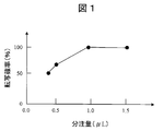
- FIG. 1 shows the dispensing amount and the transfer (dispensing) probability.
- the transfer probability here is a probability that a predetermined amount of water is formed at the tip of the syringe needle and transferred when the water is brought into contact with the cycloolefin polymer surface.
- the number of experiments is 10.
- the horizontal axis represents the dispensing amount
- the vertical axis represents the transfer probability (%).
- the transfer probability when the dispensed amount was 1.5 ⁇ L and 1.0 ⁇ L was 100%.
- the transfer probability was 60% when the dispensed amount was 0.5 ⁇ L, and the transfer probability was 50% when the dispensed amount was 0.4 ⁇ L. That is, it has been found that the transfer probability decreases when the dispensing amount is less than 0.5 ⁇ L.
- the amount of the substance to carry over is determined by the relationship between the amount adsorbed on the surface of the dispensing nozzle and the amount of the adsorbed material eluted into the next sample, and the state of the surface of the dispensing nozzle is different. In some cases, this relationship is broken. Therefore, in order to wash the adhered specimen, the automatic analyzer is equipped with a mechanism for washing the dispensing nozzle, and the outer wall of the dispensing nozzle is washed.
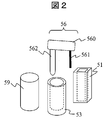
- the sample dispensing mechanism 56 includes an arm 560, a support column 562, and a sample dispensing nozzle 561.
- the dispensing nozzle sucks a sample such as serum or urine from the sample cell 53 and discharges it in the reaction cell 51 to complete the dispensing. Thereafter, the sample dispensing nozzle 561 is cleaned by the cleaning mechanism 59 as necessary.
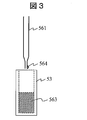
- FIG. 3 schematically shows the state of sample suction from the sample tube
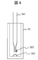
- FIG. 4 schematically shows the state of sample discharge into the cell
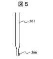
- FIG. 5 schematically shows the state of the sample dispensing nozzle after washing.
- FIG. 3, 4, and 5 are schematic diagrams corresponding to causes (1), (2), and (3), respectively.
- the present inventors have found that when the outer wall surface of the sample dispensing nozzle is subjected to water repellent treatment and the area to which the cells are dispensed is made hydrophilic, the accuracy and reproducibility of dispensing are improved.
- the outer wall surface of the sample dispensing nozzle By subjecting the outer wall surface of the sample dispensing nozzle to a water repellent treatment and making the dispensing area of the cell hydrophilic, the sample is reliably transferred to the cell and there is no decrease in dispensing accuracy.
- the nozzle is water-repellent, there is no adhesion of cleaning water.
- the nozzle may perform water repellent treatment on the inner wall surface together with the outer wall surface.
- the dispensing method there is an ink jet method.
- an automatic analyzer normally analyzes various samples in small amounts. Therefore, in the inkjet method in which a sample is stored once in a sample reservoir and then discharged, if a sample adheres to the sample reservoir, contamination to other samples cannot be ignored. In addition, cleaning the sample reservoir to which the above-mentioned dirt is attached also increases the cost. Therefore, although the present invention will be described focusing on a suction / discharge system dispensing mechanism, application to other dispensing systems such as an inkjet system is not impeded.
- the outer wall surface of the sample dispensing nozzle can be uniformly treated with water-repellent plating, so that the nozzle outer wall surface exhibits uniform water repellency. Since the outer wall surface exhibits high water repellency, the sample drains well during dispensing and the sample is not taken home.
- the accuracy and reproducibility of sample dispensing can be improved during automatic analysis by simultaneously using a nozzle whose surface is water-repellent and a cell whose hydrophilicity is applied to the dispensing area. Since the contamination of the sample on the outer wall surface of the nozzle can be prevented, cross-contamination between analyzes can be prevented and data reliability can be improved. These effects contribute to the miniaturization of samples and reagents, and also contribute to reducing the running cost of the automatic analyzer.
- the figure which shows the relationship between dispensing amount and dispensing precision The schematic diagram of the sample dispensing mechanism of an automatic analyzer.
- the figure which shows the mode of the dispensing in automatic analysis The figure which shows the mode of the dispensing in automatic analysis.
- the figure which shows the mode of the dispensing in automatic analysis Schematic diagram of sample dispensing nozzle. Sectional drawing of the nozzle tip which performed the water-repellent plating process.
- the perspective external view of a reaction cell Sectional drawing of a reaction cell.
- the schematic diagram of a corona discharge process The schematic diagram of the reaction cell bottom face made hydrophilic.
- the tip of the dispensing nozzle needs to be conductive in order to detect the liquid level and control the height of the nozzle. Therefore, for example, in the case of an automatic analyzer that selects SUS304 as a material for a dispensing nozzle and requires a liquid level detection function based on conductivity, it is necessary to impart high water repellency to the surface while maintaining conductivity. On the other hand, if the water repellency improvement by general chemical coating or chemical reaction is excessively applied to the inner wall surface or outer wall surface or both surfaces of the dispensing nozzle, the surface conductivity is lost due to the formation of an insulating film. Can not be.
- the inventors have come up with the idea that a nickel-fluorine resin eutectoid plating process is performed on the outer surface of the dispensing nozzle.
- the electroless plating of nickel-Teflon is performed on the surface of the dispensing nozzle, so that the presence of nickel in the surface plating layer provides high conductivity, high water repellency due to the fluororesin, and strong bonding to the surface. All can be achieved.
- the surface treatment can be performed on the inner wall surface and the outer wall surface of the dispensing nozzle, but a good dispensing result was obtained by uniformly water-repellent plating treatment on the outer wall surface from the result of the preliminary experiment.
- the surface of the dispensing nozzle for an automatic analyzer can be subjected to water repellent treatment and at the same time has conductivity. Moreover, if the dispensing nozzle of the present invention is used, the accuracy and reproducibility of sample dispensing is high.
- nozzles coated with diamond like carbon (DLC) nozzles with a silane coupling agent having a long chain alkyl group fixed to an appropriate thickness, and nozzles with water-repellent molecules deposited. Can be used. In the case of these surface modifications, the conductivity can be maintained by reducing the film thickness to about 100 nm or less.
- the sample dispensing mechanism it has been found that it is effective for improving dispensing accuracy to make the cell surface into which the sample is dispensed hydrophilic together with the above-mentioned water-repellent treated nozzle. Even if the sample or washing water adheres to the outer wall of the nozzle after multiple uses and the hydrophilicity of the outer wall of the nozzle is improved, the cell becomes the sample if the dispensing area of the cell to which the sample is transferred is high. It is because it is possible to hold. In particular, corona discharge was effective as a method for hydrophilizing a plastic reaction cell.
- the dispensing nozzle will not bring back the analyte sample when a very small amount of the analyte sample of about 0.2 ⁇ L is dispensed. Moreover, there is a further improvement in dispensing accuracy by optimizing the area to be hydrophilized.
- sample dispensing nozzle by water-repellent plating treatment The sample dispensing nozzle for water repellent automatic analyzer on the outer wall surface (hereinafter referred to as “nozzle”) was made of stainless steel (SUS304).
- the nozzle material may be one selected from aluminum, SUS, other metals, glass, resin, and the like.
- the nozzle tip In order to detect the liquid level, the nozzle tip needs to be electrically conductive, and it is desirable to select SUS304 from the viewpoints of workability, durability, and corrosion resistance.
- the example of a sample dispensing nozzle is described here, the same surface treatment may be performed on the reagent dispensing nozzle.
- FIG. 6 shows a cross-sectional view.
- One type of dispensing nozzle 561 has an L-shaped structure.
- the length L1 in the longitudinal direction of the L-shaped structure is 100 mm, and the short distance L2 is 50 mm.
- the tip of the nozzle has a taper structure, the outer diameter d1 is, for example, ⁇ 0.5 mm, and the inner diameter d2 of the ultrafine tip is 0.3 mm.
- the inner diameter d3 of the reverse tip of the dispensing nozzle is 0.5 mm.
- FIG. 7 is a cross-sectional view in which the nozzle tip after the water-repellent plating process is cleaved at the position of the broken line 505.
- a nozzle 561 created by processing and polishing sucks a desired amount of sample from the sample tube and discharges the sample to the reaction cell. After the nozzle holding the desired amount of sample comes into contact with the bottom surface of the reaction cell, the sample is discharged. Thereafter, the nozzle is pulled upward.
- the outer wall of the dispensing nozzle became hydrophilic as the nozzle was used, although it did not become apparent. For this reason, when the sample is discharged, part or all of the sample may adhere to the surface of the nozzle outer wall, and may be brought home by forming sample adhesion or washing water adhesion.
- the outer wall surface of the nozzle 561 was subjected to water repellent plating treatment.
- the water-repellent plating treatment can maintain stronger water repellency than a water-repellent coating by simply immersing, applying, or spraying a chemical solution.
- a method called nickel-Teflon eutectoid plating was adopted. Nickel particles called nickel strikes may be implanted in advance on the SUS surface, and then nickel-Teflon electroless plating may be performed.
- FIG. 7 shows a cross-sectional view of the nozzle tip after this water-repellent plating treatment.
- a base layer 507 such as a nickel layer can be provided on the outer wall surface of SUS506, and the water-repellent layer 508 and the plating layer 509 can be provided on the surface.
- the nozzle inner wall surface could hold the SUS surface without being subjected to the water-repellent plating treatment.
- the surface of the SUS inner wall may be mirror polished to improve the flatness.
- the outer wall surface of the nozzle can be made uniform water repellent and the inner wall surface can be made uniform hydrophilic.
- the nozzle 70 shown in FIG. 8 has margins 510 and 511 at both ends of the nozzle 561 described above, and the holes are closed in advance. This is because the SUS nozzle before drilling may be used to make the margin 510 and the margin 511 SUS, or the holes may be closed by filling rubber or resin at both ends of the nozzle after drilling.
- the nozzle 70 was subjected to water-repellent plating treatment by the following processes 1 to 3.
- Process 1 The water-repellent plating process is performed on the nozzle 70 whose holes at both ends are closed.
- Process 2 Both ends of the nozzle of Process 1 are cut to produce a perforated nozzle having a desired overall length.
- Process 3 Water-repellent plating treatment is performed on the cross section of both holes as necessary.
- the outer wall surface of the dispensing nozzle produced by the above process is water repellent, and the inner wall surface of the nozzle can be made hydrophilic by the original metal.
- the plating solution may enter the nozzle, and the surface of the nozzle inner wall may be unevenly treated with water repellent plating. . This time, the nozzle which made the water-repellent plating treatment only on the outer wall surface was produced.
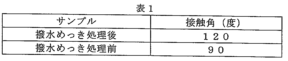
- Drop Master 500 manufactured by Kyowa Interface Science was used for measurement of the contact angle. 0.1 ⁇ L of pure water was dropped on the outer wall surface of the nozzle with a syringe, and the static contact angle 1 second after the landing was measured by a three-point method. For the measurement, the surface was measured every 1 mm, and the average value at six sites was obtained. As a result, the contact angle of the water-repellent plated nozzle with respect to water was 120 degrees. On the other hand, the water contact angle of the sample dispensing nozzle made of SUS304 before water repellent plating treatment was 90 degrees, so that the water repellency was improved by the water repellent plating treatment.
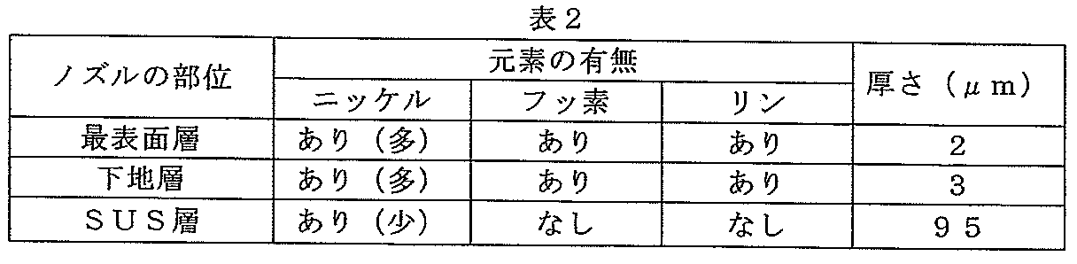
- Table 2 shows the results of electron microscopic observation and elemental analysis of the nozzle subjected to the water repellent plating treatment by SEM-EDAX (elemental analysis using an electron microscope).
- SEM-EDAX mental analysis using an electron microscope.
- a Hitachi S2460 type apparatus was used for the measurement. In order to measure the thickness of the plating, the nozzle was cleaved, and then SEM-EDAX observation was performed.
- the outermost surface layer 508 of the nozzle has nickel, fluorine, and phosphorus, and has a thickness of 2 ⁇ m.
- the underlayer 507 below the outermost surface layer 508 contains nickel, fluorine, and phosphorus, and has a thickness of 3 ⁇ m.
- nickel derived from the SUS component is present, and fluorine and phosphorus are not present. From the viewpoint of the contact angle shown in Table 1 and from the viewpoint of elemental analysis shown in Table 2, it can be seen that the water repellency of the nozzle outer wall surface is high. It was also confirmed that the uniformity among the processed cell lots was high.
- the surface of the outer wall of the dispensing nozzle may be made water repellent.
- the sample dispensing nozzle may be water-repellent at least on the outer wall region and the end surface of the nozzle tip that is immersed in the sample.
- a reaction cell (hereinafter referred to as “cell”) for a hydrophilization automatic analyzer in the cell dispensing region was manufactured by injection molding using polycycloolefin as a material.
- polycycloolefin resin one kind selected from polycycloolefin resin, polycarbonate resin, acrylic resin, and polystyrene resin can be used. It is desirable to select a polycycloolefin resin from the viewpoints of low water absorption, low moisture permeability, high total light transmittance, low refractive index, and low molding shrinkage.
- Polycycloolefin is a polymer, and the main chain and side chain of the molecule are each composed of a carbon-carbon bond and a carbon-hydrogen bond, and a cyclic saturated hydrocarbon exists in a part of the main chain.
- the automatic analyzer the specimen sample and the reagent are reacted in each single cell, and the coloring of the dye and the aggregation phenomenon of the latex are measured by the change in the light transmittance at a plurality of specific wavelengths.
- Each single cell is typically a vertically long container having a bottom wall made of resin and a side wall standing upward from the periphery of the bottom wall and having an opening at the upper end.
- the bottom wall can be rectangular or square.
- a pair of (two) parts facing each other form a photometric surface through which measurement light is transmitted.
- the pair of (two) portions facing each other form a non-photometric surface through which measurement light is not transmitted.
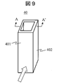
- Fig. 9 shows a perspective external view of the cell.
- the cell 40 has a photometric surface 401 and a non-photometric surface 402. Measurement light enters the photometric surface 401 from the direction of the arrow.
- the cell 40 has a non-photometric surface outer surface 111, a non-photometric surface inner surface 112, a photometric surface outer surface 113, a photometric surface inner surface 114, and a bottom wall inner surface (bottom surface) 115.
- the inner wall portion of the cell has a length L4 that is half of the non-photometric surface 3mm, a length L5 of the photometric surface 4mm, a height H 30mm, a cell thickness T 1mm, and is formed by the bottom wall 115.
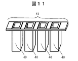
- a closing part and an upper opening part 140 are provided. As shown in FIG. 11, a plurality of cells 40 may be arranged in a line so that the openings of the respective cells face the same direction, and each cell may be hydrophilized using an integrally formed cell block 41.
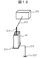
- FIG. 12 shows a schematic diagram of the corona discharge partial treatment.
- a cathode plate 213 was placed outside the bottom surface of the cleaned and dried cell 40.
- the cathode plate is connected to the ground 217 via the wiring 216.
- a rod-like electrode 214 of a corona discharge anode was placed inside the cell 40 toward the center of the bottom surface of the cell up to a height of 1 mm from the bottom surface.
- the rod-shaped electrode 214 has a lower end diameter of 2 mm and a length of 50 mm, and is connected to a corona discharge power supply 211 via a wiring 212.
- the corona discharge power source is preferably a pulse type discharge power source capable of counting the number of discharge pulses, but may be a high frequency type discharge power source.
- a pulse-type corona discharge source is used.
- the bottom surface of the cell was subjected to corona discharge treatment by applying a voltage of 25 kV.
- the pulse period was 300 pulses per second, and a processing time of 1 second, that is, 300 pulses was applied. It was confirmed with an oscilloscope that energy of about 5 joules was generated from the generated voltage and current value when corona discharge treatment was performed under these conditions.
- air is used as the atmospheric gas for the corona discharge treatment, but the corona discharge treatment may be performed in a nitrogen atmosphere.
- the corona discharge treatment is performed for each cell. However, when a plurality of cells are integrally formed as a multiple cell block, the plurality of cells may be subjected to corona discharge treatment at the same time. .
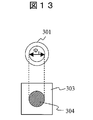
- FIG. 13 shows a state seen from above the dispensing mechanism.
- S the size of the hydrophilic region 304 of the cell bottom 303 and S.
- Drop Master 500 manufactured by Kyowa Interface Science was used for measurement of the contact angle. 1 ⁇ L of pure water was dropped onto the modified surface using a syringe, and the static contact angle 1 second after the landing was measured by a three-point method. For measurement, three treated samples were prepared and measured, and the average value was obtained.
- the contact angle of the cell surface and the non-modified portion before the surface modification was about 90 degrees, but the contact angle was reduced to 75 degrees by the surface modification.
- the maximum variation in measured values was about 3 degrees or less.
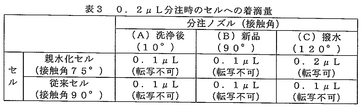
- the contact angle of the cell surface that is the discharge destination (transfer destination) of the sample is conventionally 90 °, and the contact angle of the cell hydrophilized by corona discharge is 75 °.
- dispensing nozzles (A) SUS nozzle after cleaning, (B) new SUS nozzle, (C) water-repellent nozzle) and 2 types of cells (conventional cell and hydrophilic cell) as the dispensing destination
- the dispensing amount 0.2 ⁇ L, 0.4 ⁇ L, and 0.5 ⁇ L were examined.
- each dispensing amount of water was discharged from the dispensing nozzle, the nozzle was lowered at a rate of 1 cm / min, and when the water touched the cell bottom surface, the nozzle was pulled up at a rate of 1 cm / min. If water adheres to the outer wall of the raised nozzle and is brought home, the amount of dispensing (transfer) decreases.
- a predetermined amount of water was discharged from each of the three nozzles described above, transferred to the surface of the cycloolefin polymer, and the amount transferred to the surface of the cycloolefin polymer was read from the image of the contact angle meter.
- Kyowa Interface Science Drop Master 500 was used as the contact angle meter.
- a predetermined amount of pure water was formed at the tip of the syringe, and the pure water was transferred onto the cell surface made of cycloolefin polymer.
- the number of evaluations was 10, and the case where transfer could not be performed even once was evaluated as untransferable.
- the transfer amount to the cell surface when the transfer could not be performed was estimated from the image of the contact angle meter.
- FIG. 14 is a diagram showing a configuration example of an automatic analyzer according to the present invention.
- the sample storage unit mechanism 1 is provided with one or more sample cells 25.
- the sample disk mechanism which is a disk-shaped sample storage unit mechanism, is shown, but it may be in the form of a sample rack or sample holder.
- the sample here refers to a solution to be inspected used for reacting in a reaction cell, and may be a collected specimen stock solution or a solution obtained by subjecting it to a processing such as dilution or pretreatment.
- the sample in the sample cell 25 is extracted by the water-repellent sample dispensing nozzle 27 of the sample supply dispensing mechanism 2 and injected into a predetermined reaction cell.
- the water repellent sample dispensing nozzle 27 has a water repellent plated outer wall surface and is water repellent, and the inner wall surface is metallic and hydrophilic.
- the reagent disk mechanism 5 includes a large number of reagent containers 6.
- the mechanism 5 is provided with a reagent supply dispensing mechanism 7, and the reagent is sucked and injected into a predetermined reaction cell by the reagent dispensing nozzle 28 of the mechanism 7.
- a reagent dispensing nozzle that has been subjected to water-repellent plating may also be used.
- the outer wall surface subjected to water-repellent plating treatment was used in the same manner as the nozzle 27.
- Reference numeral 10 denotes a spectrophotometer
- 26 denotes a light source with a condensing filter.
- a reaction disk 3 that accommodates a measurement target is disposed.
- 120 reaction cells 4 having a hydrophilized bottom surface are installed on the outer periphery of the reaction disk 3. Further, the entire reaction disk 3 is held at a predetermined temperature by a thermostatic chamber 9.
- Reference numeral 11 denotes a reaction cell cleaning mechanism, and the cleaning agent is supplied from the cleaning agent container 13.
- 19 is a computer, 23 is an interface, 18 is a Log converter and A / D converter, 17 is a reagent pipettor, 16 is a washing water pump, and 15 is a sample pipettor.
- Reference numeral 20 denotes a printer, 21 denotes a CRT, 22 denotes a floppy disk or hard disk as a storage device, and 24 denotes an operation panel.
- the sample disk mechanism is controlled and driven by the drive unit 100, the reagent disk mechanism is driven by the drive unit 101, and the reaction disk is driven and driven by the drive unit 102, respectively.
- Each part of the automatic analyzer is controlled by a computer via an interface.
- the operator inputs analysis request information using the operation panel 24.
- the analysis request information input by the operator is stored in a memory in the microcomputer 19.
- the sample to be measured which is placed in the sample cell 25 and set at a predetermined position in the sample disk storage unit mechanism 1, is dispensed with the sample pipettor 15 and the sample supply dispenser according to the analysis request information stored in the memory of the microcomputer 19.
- a predetermined amount is dispensed into the reaction cell by the nozzle 27 of the mechanism 2.
- the sample dispensing nozzle 27 is washed with water.
- a predetermined amount of reagent is dispensed into the reaction cell by the reagent nozzle 28 of the reagent supply dispensing mechanism 7.
- the reagent nozzle 28 After the reagent nozzle 28 is washed with water, it dispenses a reagent for the next reaction cell.
- the mixed solution of the sample and the reagent is stirred by the stirring rod 29 of the stirring mechanism 8 or the ultrasonic element.
- the stirring mechanism 8 sequentially stirs the liquid mixture in the next reaction cell.
- the reaction cell 4 is maintained at a constant temperature by a thermostat 9 and serves as both a reaction and a photometric container.
- light is supplied from a light source 26 with a condensing filter, and the reaction solution is measured by the spectrophotometer 10 at regular intervals, and the absorbance of the mixed solution is determined using one or more set wavelengths. Measured.
- a light source with a condensing filter By using a light source with a condensing filter at the time of measurement, only the hydrophilic portion of the reaction cell can be selectively transmitted.
- Measured absorbance is taken into the computer 19 through the Log converter and A / D converter 18 and the interface 23.
- the absorbed absorbance is converted into a concentration value, and the concentration value is stored in a floppy disk or hard disk 22 or output to the printer 20.
- inspection data can be displayed on the CRT 21.
- the reaction cell 4 that has been measured is washed with water by a reaction cell washing mechanism (nozzle arm) 11. After the washing is completed, water is sucked by the suction nozzle 12 and then used sequentially for the next analysis.
Landscapes
- Chemical & Material Sciences (AREA)
- Health & Medical Sciences (AREA)
- Analytical Chemistry (AREA)
- Chemical Kinetics & Catalysis (AREA)
- Physics & Mathematics (AREA)
- Life Sciences & Earth Sciences (AREA)
- Clinical Laboratory Science (AREA)
- Biochemistry (AREA)
- General Health & Medical Sciences (AREA)
- General Physics & Mathematics (AREA)
- Immunology (AREA)
- Pathology (AREA)
- Automatic Analysis And Handling Materials Therefor (AREA)
- Investigating Or Analyzing Non-Biological Materials By The Use Of Chemical Means (AREA)
Abstract
Description
自動分析装置用サンプル分注ノズル(以下、“ノズル”と呼称する。)は、ステンレススチール(SUS304)を素材として作製した。ちなみにノズルの素材としては、アルミニウム、SUS、その他金属、ガラス、樹脂などから選択される1種であればかまわない。液面検知をするにはノズル先端に導電性が必要であり、かつ加工性、耐久性、耐腐食性の観点からSUS304を選択することが望ましい。また、ここではサンプル分注ノズルの例を述べるが、試薬分注ノズルに同様の表面処理をしてもよい。
自動分析装置用反応セル(以下、“セル”と呼称する。)を、ポリシクロオレフィンを素材として射出成形によって製作した。ちなみにセル素材としては、ポリシクロオレフィン樹脂、ポリカーボネート樹脂、アクリル樹脂、ポリスチレン樹脂から選択される1種を用いることができる。低吸水率、低透湿度、高い全光線透過率、低屈折率、低成型収縮率の観点からポリシクロオレフィン樹脂を選択することが望ましい。ポリシクロオレフィンは、高分子であり、分子の主鎖及び側鎖は、それぞれ炭素-炭素結合と炭素-水素結合から構成されており、主鎖の一部に環状の飽和炭化水素が存在する。自動分析装置においては、個々の単セルの中で検体サンプルと試薬を反応させて、色素の発色やラテックスの凝集現象を複数の特定波長の光透過率の変化によって計測する。
分注ノズルを用いて、サンプルをセルに吐出する分注機構において、(1)の撥水性ノズルと、(2)の底面を親水化したセルの組み合わせによる分注性能ついて評価した。用いた分注ノズルは、SUS304製で、内径0.3mm、外径0.5mmである。ノズル表面の接触角を求めるため、ノズル先端に純水を0.2μL滴下した際の接触角を前述した方法で測定した。新品の分注ノズルの接触角は90°であるが、洗浄液での洗浄後に10°に低下する。従って、実機搭載向けのSUS304製ノズルの接触角は10°である。また撥水処理し、接触角が120°の分注ノズルを評価した。
0.2μLの水を分注した場合の分注定量結果を、表3にまとめた。SUS製のシリンジ針から所定量の水を出し、シクロオレフィンポリマー製のセル表面に転写し、セル表面に転写された量を接触角計の画像から読み取った。接触角計には、協和界面科学製Drop Master 500を使用した。所定量の純水をシリンジ先端に形成させ、シクロオレフィンポリマー表面に純水を転写した。以下に結果を示す。
0.4μLの水を分注した場合の分注定量結果を、表4にまとめた。

0.5μLの水を分注した場合の分注定量結果を、表5にまとめた。

上記(1)で作製した「外壁面が撥水性で内壁面が親水性のサンプル分注ノズル」と上記(2)で作製した「底面を親水化したセル」を同時に使用した自動分析の実施例を述べる。図14は、本発明による自動分析装置の構成例を示す図である。
2 サンプル供給用分注機構
3 反応ディスク
4 反応セル
5 試薬ディスク機構
6 試薬容器
7 試薬供給用分注機構
25 サンプルセル
27 サンプル分注ノズル
28 試薬ノズル
40 セル
41 セルブロック
51 反応セル
53 サンプルセル
56 サンプル分注機構
59 洗浄機構
70 サンプル分注ノズル
100 駆動部
101 駆動部
102 駆動部
211 コロナ放電源
213 底面用電極
214 棒状電極
303 セル底
304 親水化領域
506 SUS
507 下地層
508 撥水層
509 めっき層
560 アーム
561 サンプル分注ノズル
562 支柱
563 サンプル
564 付着サンプル
53 サンプルセル
565 付着サンプル
566 付着洗浄水
Claims (8)
- サンプルを入れるサンプルセルと、試薬を入れる試薬容器と、サンプル及び試薬が注入される反応セルと、前記サンプルセル中の試薬を前記反応セルに分注するサンプル分注機構と、前記試薬容器中の試薬を前記反応セルに分注する試薬分注機構とを有する自動分析装置において、
前記サンプル分注機構は撥水性の表面を有するサンプル分注ノズルを備え、前記反応セルは親水性の底面を有することを特徴とする自動分析装置。 - 請求項1に記載の自動分析装置において、前記反応セル底面の親水性領域は前記サンプル分注ノズルの内径より大きいもしくは等しいことを特徴とする自動分析装置。
- 請求項1に記載の自動分析装置において、前記サンプル分注ノズルは先端部分の表面及び端面が撥水性であることを特徴とする自動分析装置。
- 請求項1に記載の自動分析装置において、前記サンプル分注機構によるサンプル分注量は0.4μL以下であることを特徴とする自動分析装置。
- 自動分析装置用に用いられるサンプル分注ノズルであって、ノズルの先端表面が撥水性でかつ導電性を有することを特徴とするサンプル分注ノズル。
- 請求項5に記載のサンプル分注ノズルにおいて、前記ノズルの先端外壁表面が撥水性でかつ導電性を有し、先端内壁表面が親水性であることを特徴とするサンプル分注ノズル。
- 請求項5に記載の分注ノズルであって、前記ノズル先端表面の撥水性部分の組成にフッ素と炭素とニッケルを含むことを特徴とするサンプル分注ノズル。
- 請求項5に記載の分注ノズルであって、前記ノズルは先端部分の内径が0.5mm以下であり、外径が1.0mm以下であることを特徴とするサンプル分注ノズル。
Priority Applications (3)
| Application Number | Priority Date | Filing Date | Title |
|---|---|---|---|
| CN2010800060924A CN102317794A (zh) | 2009-03-27 | 2010-01-05 | 自动分析装置及自动分析装置用分注管嘴 |
| DE112010001385T DE112010001385B4 (de) | 2009-03-27 | 2010-01-05 | Analyseautomat und Pipettierspitze für einen Analyseautomaten |
| US13/147,152 US8444936B2 (en) | 2009-03-27 | 2010-01-05 | Autoanalyzer and pipetting nozzle for autoanalyzer |
Applications Claiming Priority (2)
| Application Number | Priority Date | Filing Date | Title |
|---|---|---|---|
| JP2009079897A JP5097737B2 (ja) | 2009-03-27 | 2009-03-27 | 自動分析装置及びサンプル分注ノズル |
| JP2009-079897 | 2009-03-27 |
Publications (1)
| Publication Number | Publication Date |
|---|---|
| WO2010109927A1 true WO2010109927A1 (ja) | 2010-09-30 |
Family
ID=42780624
Family Applications (1)
| Application Number | Title | Priority Date | Filing Date |
|---|---|---|---|
| PCT/JP2010/050017 Ceased WO2010109927A1 (ja) | 2009-03-27 | 2010-01-05 | 自動分析装置及び自動分析装置用分注ノズル |
Country Status (5)
| Country | Link |
|---|---|
| US (1) | US8444936B2 (ja) |
| JP (1) | JP5097737B2 (ja) |
| CN (1) | CN102317794A (ja) |
| DE (1) | DE112010001385B4 (ja) |
| WO (1) | WO2010109927A1 (ja) |
Cited By (2)
| Publication number | Priority date | Publication date | Assignee | Title |
|---|---|---|---|---|
| US20120164325A1 (en) * | 2010-12-27 | 2012-06-28 | Nhk Spring Co., Ltd. | Method of forming lubricative plated layer on viscous liquid feed nozzle and viscous liquid feed nozzle |
| JP2017173044A (ja) * | 2016-03-22 | 2017-09-28 | キヤノンマシナリー株式会社 | 分注ノズルおよび分注ノズルの製造方法 |
Families Citing this family (16)
| Publication number | Priority date | Publication date | Assignee | Title |
|---|---|---|---|---|
| WO2012162101A1 (en) * | 2011-05-20 | 2012-11-29 | Geneforge, Inc. | Drop-in nozzle |
| JP2013134140A (ja) * | 2011-12-26 | 2013-07-08 | Hitachi High-Technologies Corp | 自動分析装置および自動分析装置における検体分注方法 |
| EP2872869B1 (en) * | 2012-07-13 | 2020-05-27 | Roche Diagnostics Hematology, Inc. | Controlled dispensing of samples onto substrates |
| EP2711080B1 (de) * | 2012-09-24 | 2019-04-10 | Siemens Healthcare Diagnostics Products GmbH | Hohlnadel für einen probenpipettor |
| JP6204657B2 (ja) * | 2012-12-03 | 2017-09-27 | 太陽誘電ケミカルテクノロジー株式会社 | 撥水性の非晶質炭素膜を有するフィルター |
| US10416046B2 (en) | 2013-04-11 | 2019-09-17 | Rarecyte, Inc. | Device, system, and method for selecting a target analyte |
| US9227188B2 (en) * | 2013-04-11 | 2016-01-05 | Rarecyte, Inc. | Device, system, and method for selecting a target analyte or fluid |
| WO2015092844A1 (ja) * | 2013-12-16 | 2015-06-25 | 株式会社島津製作所 | 液採取装置及びその液採取装置を備えた自動分析装置 |
| US11185227B2 (en) | 2015-09-30 | 2021-11-30 | Tata Consultancy Services Limited | Method and system for automated healthcare monitoring of a patient |
| CN109844490A (zh) | 2016-10-19 | 2019-06-04 | 豪夫迈·罗氏有限公司 | 用于生物样品的染色的系统和方法 |
| EP3555634B1 (en) * | 2016-12-16 | 2023-09-06 | Ventana Medical Systems, Inc. | Dispenser nozzle residue mitigation |
| US11033903B2 (en) * | 2017-06-08 | 2021-06-15 | Integra Biosciences Ag | Sample and reagent containers with anti-vacuum feature |
| EP3732491B1 (en) * | 2017-12-29 | 2024-11-06 | Beckman Coulter, Inc. | Sample analysis system comprising a probe washing arrangement and method of using it |
| JP6992901B2 (ja) * | 2018-08-06 | 2022-01-13 | 株式会社島津製作所 | 試料注入装置 |
| CN109679836B (zh) * | 2019-01-14 | 2020-09-08 | 中国水产科学研究院黄海水产研究所 | 应用于对虾病原高通量检测的玻片微量检测系统 |
| CN113567189B (zh) * | 2021-08-09 | 2024-11-29 | 重庆水务集团龙兴排水有限公司 | 一种用于水质采样系统的留样装置及方法 |
Citations (8)
| Publication number | Priority date | Publication date | Assignee | Title |
|---|---|---|---|---|
| JPS5844349A (ja) * | 1981-07-20 | 1983-03-15 | テクニコン・インストルメンツ・コ−ポレ−シヨン | カツプ状容器及び反応トレイ |
| JPH01274866A (ja) * | 1988-04-28 | 1989-11-02 | Fuji Photo Film Co Ltd | 管の先端付近の撥水性処理 |
| JPH06174603A (ja) * | 1992-12-10 | 1994-06-24 | Olympus Optical Co Ltd | 自動分析装置の分注装置 |
| JP2004136236A (ja) * | 2002-10-18 | 2004-05-13 | Sumitomo Bakelite Co Ltd | 分注用チップ |
| JP2007183240A (ja) * | 2005-12-06 | 2007-07-19 | Hitachi High-Technologies Corp | 自動分析装置用反応セルとその製造方法、その反応セルを搭載した自動分析装置、及び分析方法 |
| JP2008256525A (ja) * | 2007-04-04 | 2008-10-23 | Olympus Corp | 液体接触部品 |
| JP2008286539A (ja) * | 2007-05-15 | 2008-11-27 | Hitachi High-Technologies Corp | 自動分析装置の反応セル、および自動分析装置用反応セルの表面仕上法 |
| JP2009058437A (ja) * | 2007-08-31 | 2009-03-19 | Olympus Corp | 分注ノズル及び自動分析装置 |
Family Cites Families (15)
| Publication number | Priority date | Publication date | Assignee | Title |
|---|---|---|---|---|
| EP0339622B1 (en) | 1988-04-28 | 1994-12-21 | Fuji Photo Film Co., Ltd. | Method and apparatus for water-repellent processing of tube |
| JPH0375827A (ja) | 1989-08-18 | 1991-03-29 | Toshiba Corp | コピー防止装置 |
| JPH06117970A (ja) * | 1992-10-05 | 1994-04-28 | Fujikura Ltd | 液体供給管の構造 |
| JPH06336593A (ja) | 1993-05-27 | 1994-12-06 | Tonen Corp | 潤滑油組成物 |
| US6069027A (en) * | 1997-05-21 | 2000-05-30 | Lsi Logic Corporation | Fixture for lid-attachment for encapsulated packages |
| JP3474774B2 (ja) * | 1998-05-29 | 2003-12-08 | リコーマイクロエレクトロニクス株式会社 | インクジェットヘッドのノズルプレートの製造方法 |
| EP0977039B1 (en) | 1998-07-27 | 2010-04-07 | Hitachi, Ltd. | Handling method of body fluid sample and analysis apparatus using the same |
| JP3380542B2 (ja) | 1998-07-27 | 2003-02-24 | 株式会社日立製作所 | 生体サンプルの分析方法 |
| JP2000329771A (ja) | 1999-05-18 | 2000-11-30 | Olympus Optical Co Ltd | 分注装置 |
| JP2002355977A (ja) * | 2001-02-08 | 2002-12-10 | Canon Inc | 撥液部材、該撥液部材を用いたインクジェットヘッド、それらの製造方法及びインクの供給方法 |
| JP2003088733A (ja) * | 2001-09-20 | 2003-03-25 | Canon Inc | 気液分離膜およびその製造方法 |
| EP1498274B1 (en) * | 2003-07-15 | 2006-04-05 | Konica Minolta Medical & Graphic Inc. | Inkjet printer using ultraviolet cure ink |
| JP2005209832A (ja) * | 2004-01-22 | 2005-08-04 | Matsushita Electric Ind Co Ltd | レーザ発振装置とその製造方法およびレーザ加工機 |
| JP2006006358A (ja) | 2004-06-22 | 2006-01-12 | Green Consumer:Kk | 携帯用シミ取りスプレー |
| JP2006058031A (ja) * | 2004-08-17 | 2006-03-02 | Hitachi High-Technologies Corp | 化学分析装置 |
-
2009
- 2009-03-27 JP JP2009079897A patent/JP5097737B2/ja active Active
-
2010
- 2010-01-05 DE DE112010001385T patent/DE112010001385B4/de active Active
- 2010-01-05 US US13/147,152 patent/US8444936B2/en active Active
- 2010-01-05 WO PCT/JP2010/050017 patent/WO2010109927A1/ja not_active Ceased
- 2010-01-05 CN CN2010800060924A patent/CN102317794A/zh active Pending
Patent Citations (8)
| Publication number | Priority date | Publication date | Assignee | Title |
|---|---|---|---|---|
| JPS5844349A (ja) * | 1981-07-20 | 1983-03-15 | テクニコン・インストルメンツ・コ−ポレ−シヨン | カツプ状容器及び反応トレイ |
| JPH01274866A (ja) * | 1988-04-28 | 1989-11-02 | Fuji Photo Film Co Ltd | 管の先端付近の撥水性処理 |
| JPH06174603A (ja) * | 1992-12-10 | 1994-06-24 | Olympus Optical Co Ltd | 自動分析装置の分注装置 |
| JP2004136236A (ja) * | 2002-10-18 | 2004-05-13 | Sumitomo Bakelite Co Ltd | 分注用チップ |
| JP2007183240A (ja) * | 2005-12-06 | 2007-07-19 | Hitachi High-Technologies Corp | 自動分析装置用反応セルとその製造方法、その反応セルを搭載した自動分析装置、及び分析方法 |
| JP2008256525A (ja) * | 2007-04-04 | 2008-10-23 | Olympus Corp | 液体接触部品 |
| JP2008286539A (ja) * | 2007-05-15 | 2008-11-27 | Hitachi High-Technologies Corp | 自動分析装置の反応セル、および自動分析装置用反応セルの表面仕上法 |
| JP2009058437A (ja) * | 2007-08-31 | 2009-03-19 | Olympus Corp | 分注ノズル及び自動分析装置 |
Cited By (4)
| Publication number | Priority date | Publication date | Assignee | Title |
|---|---|---|---|---|
| US20120164325A1 (en) * | 2010-12-27 | 2012-06-28 | Nhk Spring Co., Ltd. | Method of forming lubricative plated layer on viscous liquid feed nozzle and viscous liquid feed nozzle |
| US8859039B2 (en) * | 2010-12-27 | 2014-10-14 | Nhk Spring Co., Ltd. | Method of forming lubricative plated layer on viscous liquid feed nozzle and viscous liquid feed nozzle |
| US9844789B2 (en) | 2010-12-27 | 2017-12-19 | Nhk Spring Co., Ltd. | Method of forming lubricative plated layer on viscous liquid feed nozzle and viscous liquid feed nozzle |
| JP2017173044A (ja) * | 2016-03-22 | 2017-09-28 | キヤノンマシナリー株式会社 | 分注ノズルおよび分注ノズルの製造方法 |
Also Published As
| Publication number | Publication date |
|---|---|
| CN102317794A (zh) | 2012-01-11 |
| DE112010001385B4 (de) | 2013-11-21 |
| DE112010001385T5 (de) | 2012-05-24 |
| JP2010230566A (ja) | 2010-10-14 |
| US8444936B2 (en) | 2013-05-21 |
| JP5097737B2 (ja) | 2012-12-12 |
| US20110300035A1 (en) | 2011-12-08 |
Similar Documents
| Publication | Publication Date | Title |
|---|---|---|
| JP5097737B2 (ja) | 自動分析装置及びサンプル分注ノズル | |
| JP4938082B2 (ja) | 洗浄装置、吸引ノズルの詰り検知方法及び自動分析装置 | |
| JP4938083B2 (ja) | 洗浄装置、洗浄ノズルの詰り検知方法及び自動分析装置 | |
| JP4251627B2 (ja) | 化学分析装置及びその分注方法 | |
| CN111819449B (zh) | 自动分析装置 | |
| WO2008057758A2 (en) | Method and device for cleaning a liquid aspiration and dispense probe | |
| JP5028350B2 (ja) | 自動分析装置 | |
| WO2007148485A1 (ja) | 分注装置および分析装置 | |
| US6463969B1 (en) | Liquid sample dispensing methods for precisely delivering liquids without crossover | |
| Chai et al. | Practical considerations of liquid handling devices in drug discovery | |
| JP2004251797A (ja) | 自動分析装置 | |
| JP7495867B2 (ja) | 自動分析装置 | |
| JP4422658B2 (ja) | 液体分注装置 | |
| WO2010109926A1 (ja) | 自動分析装置用分注ノズルとその製造方法及びそれを搭載した自動分析装置 | |
| JP2007093220A (ja) | 自動分析装置 | |
| JP6731311B2 (ja) | 自動分析装置 | |
| WO2016031353A1 (ja) | 自動分析装置用反応セル、その反応セルを搭載した自動分析装置、及びその自動分析装置を用いた分析方法 | |
| JP4839269B2 (ja) | 自動分析装置用反応セルの製造用電極、その電極を使用した製造方法 | |
| AU2022439197B2 (en) | Device and method to be carried out for examining and/or processing an in particular biological or medical sample | |
| US20090123958A1 (en) | Laboratory Devices, Methods and Systems Employing Acoustic Ejection Devices | |
| JP7309467B2 (ja) | 自動分析装置 | |
| JP3407068B2 (ja) | 化学分析装置 | |
| JP2004325138A (ja) | 試料供給装置及びこれを用いた測定装置 | |
| JPH06289033A (ja) | 生化学分析方法 | |
| JP2007322148A (ja) | 分注管およびそれを用いた分析装置 |
Legal Events
| Date | Code | Title | Description |
|---|---|---|---|
| WWE | Wipo information: entry into national phase |
Ref document number: 201080006092.4 Country of ref document: CN |
|
| 121 | Ep: the epo has been informed by wipo that ep was designated in this application |
Ref document number: 10755728 Country of ref document: EP Kind code of ref document: A1 |
|
| WWE | Wipo information: entry into national phase |
Ref document number: 13147152 Country of ref document: US |
|
| WWE | Wipo information: entry into national phase |
Ref document number: 112010001385 Country of ref document: DE Ref document number: 1120100013853 Country of ref document: DE |
|
| 122 | Ep: pct application non-entry in european phase |
Ref document number: 10755728 Country of ref document: EP Kind code of ref document: A1 |