WO2010109578A1 - インク充填方法 - Google Patents
インク充填方法 Download PDFInfo
- Publication number
- WO2010109578A1 WO2010109578A1 PCT/JP2009/055660 JP2009055660W WO2010109578A1 WO 2010109578 A1 WO2010109578 A1 WO 2010109578A1 JP 2009055660 W JP2009055660 W JP 2009055660W WO 2010109578 A1 WO2010109578 A1 WO 2010109578A1
- Authority
- WO
- WIPO (PCT)
- Prior art keywords
- ink
- flow path
- suction
- air
- ink supply
- Prior art date
- Legal status (The legal status is an assumption and is not a legal conclusion. Google has not performed a legal analysis and makes no representation as to the accuracy of the status listed.)
- Ceased
Links
Images


Classifications
-
- B—PERFORMING OPERATIONS; TRANSPORTING
- B41—PRINTING; LINING MACHINES; TYPEWRITERS; STAMPS
- B41J—TYPEWRITERS; SELECTIVE PRINTING MECHANISMS, i.e. MECHANISMS PRINTING OTHERWISE THAN FROM A FORME; CORRECTION OF TYPOGRAPHICAL ERRORS
- B41J2/00—Typewriters or selective printing mechanisms characterised by the printing or marking process for which they are designed
- B41J2/005—Typewriters or selective printing mechanisms characterised by the printing or marking process for which they are designed characterised by bringing liquid or particles selectively into contact with a printing material
- B41J2/01—Ink jet
- B41J2/17—Ink jet characterised by ink handling
- B41J2/175—Ink supply systems ; Circuit parts therefor
-
- B—PERFORMING OPERATIONS; TRANSPORTING
- B41—PRINTING; LINING MACHINES; TYPEWRITERS; STAMPS
- B41J—TYPEWRITERS; SELECTIVE PRINTING MECHANISMS, i.e. MECHANISMS PRINTING OTHERWISE THAN FROM A FORME; CORRECTION OF TYPOGRAPHICAL ERRORS
- B41J2/00—Typewriters or selective printing mechanisms characterised by the printing or marking process for which they are designed
- B41J2/005—Typewriters or selective printing mechanisms characterised by the printing or marking process for which they are designed characterised by bringing liquid or particles selectively into contact with a printing material
- B41J2/01—Ink jet
- B41J2/17—Ink jet characterised by ink handling
- B41J2/175—Ink supply systems ; Circuit parts therefor
- B41J2/17503—Ink cartridges
- B41J2/17506—Refilling of the cartridge
- B41J2/17509—Whilst mounted in the printer
-
- B—PERFORMING OPERATIONS; TRANSPORTING
- B41—PRINTING; LINING MACHINES; TYPEWRITERS; STAMPS
- B41J—TYPEWRITERS; SELECTIVE PRINTING MECHANISMS, i.e. MECHANISMS PRINTING OTHERWISE THAN FROM A FORME; CORRECTION OF TYPOGRAPHICAL ERRORS
- B41J2/00—Typewriters or selective printing mechanisms characterised by the printing or marking process for which they are designed
- B41J2/005—Typewriters or selective printing mechanisms characterised by the printing or marking process for which they are designed characterised by bringing liquid or particles selectively into contact with a printing material
- B41J2/01—Ink jet
- B41J2/17—Ink jet characterised by ink handling
- B41J2/175—Ink supply systems ; Circuit parts therefor
- B41J2/17596—Ink pumps, ink valves
Definitions
- the present invention relates to an ink filling method for a print head having a plurality of ink supply ports in an inkjet printer. More specifically, the present invention relates to an ink filling method capable of filling ink so as not to leave air in a flow path member.
- a print head supplies ink from an ink supply source (ink tank) to an ink supply port of a head unit via an ink flow path, and a number of plate-type piezoelectric actuators attached to the head unit A predetermined pressure is selectively applied to a pressure chamber communicating with the nozzle holes, and each ink is ejected from the nozzle holes.
- the ink supply port of the head unit is connected to a resin flow channel member (ink tube) that forms an ink flow channel that is continuous with the ink flow channel.
- the flow channel member is connected to the ink tank. Ink is supplied from the ink tank to the head unit via the flow path member.
- a plurality of ink supply ports are provided in the head unit, and ink is supplied to the plurality of ink supply ports from one ink channel through a branch channel (for example, Patent Document 1). ).
- the ink is distributed and supplied to a plurality of locations on the nozzle plate in order to uniformly eject the ink from the entire surface of the nozzle plate provided at the lower part of the head unit.
- the ink supply port of the head unit has one ink flow path continuous from the ink supply source, and a plurality of branches branched from the ink flow path and communicated with the plurality of ink supply ports. It is set as the structure by which the flow-path member provided with a flow path was mounted
- the present invention has been devised in view of such a conventional situation, and does not leave air that causes ejection failure in the flow path member when ink is filled into a print head having a plurality of ink supply ports. It is an object of the present invention to provide an ink filling method capable of filling the ink.
- the ink filling method according to claim 1 of the present invention includes a head unit that has a plurality of ink supply ports to which ink is supplied, discharges the ink from a nozzle plate provided at a lower portion thereof, and performs recording.
- An ink supply source provided outside the head unit, a single ink flow path communicating with the ink supply source, and a plurality of branches branched from the ink flow path and communicating with the plurality of ink supply ports, respectively.
- An ink filling method for a print head comprising a flow path member, wherein a suction member having a pump is mounted in an airtight manner on the nozzle plate, and the ink is supplied by sucking with the pump.
- the ink filling method according to the first aspect is characterized in that the standby and re-suction operations are repeated a plurality of times.
- the ink filling method according to claim 3 of the present invention is characterized in that in claim 1 or 2, the ink suction speed is 0.16 cc / sec or more and 0.29 cc / sec or less.
- an ink jet printer having an ink filling function using the ink filling method according to any one of the first to third aspects.
- ink when ink is filled into a print head having a plurality of ink supply ports, ink is sucked by a pump, the ink is stopped when ink passes through one branch flow path, and air moves to a branch portion of the flow path member.
- the ink suction is performed again after waiting for a predetermined time.
- the amount of air in the branching channel can be made almost equal, and the channel resistance in the branching channel becomes almost the same, so that the ink is sucked again after that.
- the inside of both branch channels can be sucked in the same way.
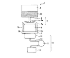
- FIG. 3 is a diagram schematically illustrating a configuration example of a print head.
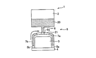
- the filling method of this invention it is a figure which shows typically the flow of the ink in a head.
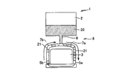
- the filling method of this invention it is a figure which shows typically the flow of the ink in a head.
- the conventional filling method it is a figure which shows typically the flow of the ink in a head.
- the conventional filling method it is a figure which shows typically the flow of the ink in a head.
- FIG. 1 is a diagram schematically showing a configuration example of a print head in which ink filling is performed by the method of the present invention.
- the print head 1 is mounted on an ink jet printer head and ejects ink 20 supplied from an ink tank 2 as an ink supply source from a number of nozzle holes (not shown) of a nozzle plate 4 provided in the head unit 3. Is printed and recorded.
- the print head 1 has a configuration in which a plurality of (here, two) ink supply ports 5 a and 5 b are provided at both ends of the head unit 3. This is because the ink is distributed and supplied to a plurality of locations on both sides of the nozzle plate 4 in order to discharge ink uniformly from the entire surface of the nozzle plate 4 provided at the lower part of the head unit 3. That is, the ink supply ports 5a and 5b of the head unit 3 are connected to one ink flow path 6 communicating with the ink tank 2, and branched from the ink flow path 6 to communicate with the respective ink supply ports 5a and 5b.
- a flow path member 8 including a plurality of branch flow paths 7a and 7b is mounted.
- These flow path members 8 are made of, for example, a flexible synthetic resin tube.
- a suction member 10 having a pump 11 is attached to the nozzle plate 4 in an airtight manner, and suction is performed by the pump 11.
- the ink 20 is supplied to the ink supply ports 5a and 5b through the flow path member 8.
- the suction member 10 includes a cap 12 having a size that fits in an airtight manner with the nozzle surface side of the print head 1.
- a through-hole (not shown) is formed on the inner bottom surface of the cap 12, and this through-hole passes through a flexible synthetic resin suction tube 13 attached to the bottom surface side of the cap 12. It is connected to the waste ink tank 14.
- a suction pump 11 is attached in the middle of the suction tube 13. Then, the suction pump 11 is driven so that negative pressure is applied to the head unit 3 side. Then, the ink stored in the ink tank 2 flows into the head unit 3 from the respective ink supply ports 5 a and 5 b via the flow path member 8.
- the ink consumption during the normal printing operation is such that a gentle flow is generated in the entire ink, and the ink supply to the head unit 3 is performed without excess or deficiency with respect to the ink supply to each nozzle.
- air that may enter the flow path needs to be discharged, and thus a purge process is performed.
- a strong flow is caused in the ink 20 and the air 21 is discharged together with the ink 20.
- the flow resistance in the branch flow paths 7a and 7b is unbalanced, the ink 20 tends to flow even if it has a low flow resistance.
- FIGS. 2 and 3 to be described later are diagrams schematically showing the flow of ink in the print head 1 during ink filling, and the suction member 10 is omitted.
- the suction pump 11 merely draws ink for a certain period of time. Then, as shown in FIG. 4, for example, the ink 20 flows only in the branch passage 7a that is easy to pass, and the ink 20 does not flow so much in the other branch passage 7b.
- ink filling in a state where ink has not yet passed a number of ink 20 layers and air 21 layers flow in succession.
- the branch flow path through which the ink easily passes is the branch flow path 7a having the smaller number of layers of the ink 20 and the air 21. If the number of layers is small, the channel resistance is reduced accordingly. Since the branch flow path 7a, which has previously lost the air 21 layer, has a significantly lower flow resistance than the branch flow path 7b in which the air 21 remains, the ink 20 flows only from there. become.
- the ink 20 is pulled only from the easier branching flow path 7a, Even if the air 21 passes through the head, it flows to the other branch flow path 7b and circulates. As a result, the air 21 does not escape indefinitely.
- the suction is stopped when the ink 20 passes through one branch flow path, and a predetermined time is waited until the air 21 in the other branch flow path moves to the branch portion 8a. After the air 21 moves to the branch part 8a, the suction is performed again. As shown in FIG. 2, the amount of the air 21 in the two branch flow paths 7a and 7b can be made substantially equal by moving the air 21 to the branch portion 8a, and thereby the two branch flow paths 7a. , 7b can have substantially the same flow path resistance. Thereafter, by performing ink suction again, the inside of both branch flow paths 7a and 7b can be sucked in the same manner. As a result, in the present invention, the air 21 can be excluded from the flow path member 8, and ink can be filled in the flow path member 8 so as not to leave the air 21 that causes ejection failure.
- both branch flow paths 7a and 7b When the amount of air 21 is equalized in both branch flow paths 7a and 7b, the flow resistances in both branch flow paths 7a and 7b become substantially the same. Then, as shown in FIG. 3 (b), the inside of both branch flow paths 7a, 7b can be sucked in the same way, and the air 21 is drawn from the branch flow paths 7a, 7b as shown in FIG. 3 (c). It becomes possible to eliminate.
- the ink suction speed is preferably 0.16 cc / sec or more and 0.29 cc / sec or less.
- the air 21 in the branch flow paths 7a and 7b which can cause ejection failure, can be efficiently removed, and ink can be reliably charged so that the air 21 does not remain in the branch flow paths 7a and 7b. It becomes possible.
- the ink suction speed is made higher than 0.29 cc / sec, the ink flow as shown in FIG. Can not.
- the ink suction speed is less than 0.16 cc / sec, the suction force is weak and the air 21 cannot be pulled. That is, since the buoyancy of the air 21 is larger than the suction force, the ink 20 only flows through the gap between the tube and the air 21 in the branch flow paths 7a and 7b. Air 21 remains in 7b.
- the ink suction speed refers to two branched flow paths in a state where a tube having an inner diameter of 3 mm and a length of 65 mm is used as the flow path member 8 and the ink 20 is completely filled in the tube. This is the speed at which the ink 20 flows in one branch channel when ink is evenly drawn from 7a and 7b.
- the air is moved to the branch portion of the flow path member by waiting for a predetermined time, and then the ink is sucked again so that the inside of both branch flow paths is the same. Can be aspirated.
- it is possible to exclude air from the inside of the flow path member, and it is possible to fill with ink so as not to leave air that causes ejection failure in the flow path member.
- the present invention is not limited to this, and can be changed as appropriate without departing from the spirit of the invention.
- the case where ink is filled in a print head having two ink supply ports has been described as an example.
- the present invention is not limited to this, and three or more ink supply ports are provided.
- the present invention can also be applied to the case where ink is filled in a print head having the same.
- the present invention is applicable to an ink filling method for a print head having a plurality of ink supply ports.
Landscapes
- Ink Jet (AREA)
Abstract
Description
これは、ヘッドユニットの下部に備えられたノズルプレートの全面から均一にインクを吐出するために、ノズルプレートの複数箇所に分配してインクを供給するためである。つまり、上記の例では、ヘッドユニットのインク供給口に、インク供給源から連なる一本のインク流路、及び、該インク流路から分岐して前記複数のインク供給口にそれぞれ連通する複数の分岐流路を備える流路部材が装着された構成とされている。
また、本発明の請求項2に記載のインク充填方法は、請求項1において、前記待機及び再吸引の動作を複数回繰り返すことを特徴とする。
また、本発明の請求項3に記載のインク充填方法は、請求項1又は2において、インク吸引速度が、0.16cc/sec以上、0.29cc/sec以下であることを特徴とする。
また、本発明の請求項4に記載のインクジェットプリンタは、請求項1~3のいずれか1項に記載のインク充填方法を用いたインク充填機能を備えることを特徴とする。
図1は、本発明の方法によりインク充填が行われる印字ヘッドの構成例を模式的に示す図である。
この印字ヘッド1は、インクジェットプリンタヘッドに装着され、インク供給源であるインクタンク2から供給されるインク20を、ヘッドユニット3が備えるノズルプレート4の多数のノズル孔(図示せず)から吐出させて印字記録するものである。
このような印字ヘッド1にインクを充填する際には、前記ノズルプレート4に、ポンプ11を有する吸引部材10を気密状に装着し、該ポンプ11により吸引することにより、前記インクタンク2内のインク20を前記流路部材8を介してそれぞれの前記インク供給口5a,5bへ供給する。
そして、吸引ポンプ11を駆動させてヘッドユニット3側に負圧力がかかるようにする。すると、インクタンク2内に蓄えられているインクは、前記流路部材8を介してそれぞれのインク供給口5a,5bからヘッドユニット3内に流れ込む。
従来の充填方法では、吸引ポンプ11で一定時間インクを引き続けるのみであった。そうすると、例えば図4に示すように、インク20は通りやすい方の分岐流路7aのみに流れ、もう一方の分岐流路7bにはインク20はあまり流れない。
そして、先に空気21の層が無くなった方の分岐流路7aは、空気21の残っている分岐流路7bに比べ、圧倒的に流路抵抗が下がるため、そちらからのみインク20が流れるようになる。
図2に示すように、分岐部8aに空気21を移動させることで、2つの分岐流路7a,7b内の空気21の量をほぼ均等にすることができ、これにより2つの分岐流路7a,7b内の流路抵抗をほぼ同じとすることができる。その後、再度インク吸引を行うことで両方の分岐流路7a,7b内を同じように吸引することができる。その結果、本発明では、流路部材8内から空気21を排除することができ、流路部材8内に吐出不良の原因となる空気21を残さないようにインク充填することが可能となる。
また、時間がたつと空気21の層どうしがくっつき、1つの大きな空気21の層へと変化する。両分岐流路7a,7b内で空気21の量が均等になると、両分岐流路7a,7b内の流路抵抗がほぼ同じとなる。すると、図3(b)に示すように両方の分岐流路7a,7b内を同じように吸引することができ、図3(c)に示すように分岐流路7a,7b内から空気21を排除することが可能となる。
例えば上述した説明では、インク供給口を2つ有する印字ヘッドにインクを充填する場合を例に挙げて説明したが、本発明はこれに限定されるものではなく、3つ以上のインク供給口を有する印字ヘッドにインクを充填する場合においても、本発明は適用可能である。
Claims (4)
- インクが供給される複数のインク供給口を有するとともに、下部に備えられたノズルプレートから前記インクを吐出して記録をするヘッドユニットと、
前記ヘッドユニットの外部に設けられたインク供給源と、
前記インク供給源に連通した一本のインク流路、及び、該インク流路から分岐して前記複数のインク供給口にそれぞれ連通する複数の分岐流路を備える流路部材と、を有する印字ヘッドへのインク充填方法であって、
前記ノズルプレートに、ポンプを有する吸引部材を気密状に装着し、該ポンプにより吸引することにより、前記インク供給源内のインクを前記流路部材を介してそれぞれの前記インク供給口へ供給する際に、
一つの分岐流路にインクが通ったところで前記吸引を止め、
前記流路部材内の空気が前記分岐部に移動するまで所定時間待機し、
前記分岐部に空気が移動した後、再度吸引を行うことを特徴とするインク充填方法。 - 前記待機及び再吸引の動作を複数回繰り返すことを特徴とする請求項1に記載のインク充填方法。
- インク吸引速度が、0.16cc/sec以上、0.29cc/sec以下であることを特徴とする請求項1又は2に記載のインク充填方法。
- 請求項1~3のいずれか1項に記載のインク充填方法を用いたインク充填機能を備えることを特徴とするインクジェットプリンタ。
Priority Applications (4)
| Application Number | Priority Date | Filing Date | Title |
|---|---|---|---|
| CN2009801579061A CN102341241A (zh) | 2009-03-23 | 2009-03-23 | 墨水填充方法 |
| PCT/JP2009/055660 WO2010109578A1 (ja) | 2009-03-23 | 2009-03-23 | インク充填方法 |
| JP2011505690A JPWO2010109578A1 (ja) | 2009-03-23 | 2009-03-23 | インク充填方法 |
| US13/257,598 US8382263B2 (en) | 2009-03-23 | 2009-03-23 | Ink filling method |
Applications Claiming Priority (1)
| Application Number | Priority Date | Filing Date | Title |
|---|---|---|---|
| PCT/JP2009/055660 WO2010109578A1 (ja) | 2009-03-23 | 2009-03-23 | インク充填方法 |
Publications (1)
| Publication Number | Publication Date |
|---|---|
| WO2010109578A1 true WO2010109578A1 (ja) | 2010-09-30 |
Family
ID=42780287
Family Applications (1)
| Application Number | Title | Priority Date | Filing Date |
|---|---|---|---|
| PCT/JP2009/055660 Ceased WO2010109578A1 (ja) | 2009-03-23 | 2009-03-23 | インク充填方法 |
Country Status (4)
| Country | Link |
|---|---|
| US (1) | US8382263B2 (ja) |
| JP (1) | JPWO2010109578A1 (ja) |
| CN (1) | CN102341241A (ja) |
| WO (1) | WO2010109578A1 (ja) |
Families Citing this family (5)
| Publication number | Priority date | Publication date | Assignee | Title |
|---|---|---|---|---|
| EP2837499B1 (en) | 2012-05-23 | 2019-10-16 | Seiko Epson Corporation | Cartridge and sealing member |
| US9776418B2 (en) | 2012-07-23 | 2017-10-03 | Seiko Epson Corporation | Method and apparatus for manufacturing cartridge |
| JP6069964B2 (ja) | 2012-07-23 | 2017-02-01 | セイコーエプソン株式会社 | カートリッジの製造方法、注入キット、及び、注入装置 |
| US10384454B2 (en) | 2012-07-23 | 2019-08-20 | Seiko Epson Corporation | Refilled cartridge and method for manufacturing refilled cartridge |
| JP6048004B2 (ja) * | 2012-07-23 | 2016-12-21 | セイコーエプソン株式会社 | カートリッジ |
Citations (4)
| Publication number | Priority date | Publication date | Assignee | Title |
|---|---|---|---|---|
| JP2002103645A (ja) * | 2000-10-03 | 2002-04-09 | Canon Inc | インクジェット記録装置 |
| JP2004114411A (ja) * | 2002-09-25 | 2004-04-15 | Canon Inc | インク供給装置及びインク供給方法 |
| JP2005161130A (ja) * | 2003-11-28 | 2005-06-23 | Seiko Epson Corp | 吐出ヘッド機構およびこれを備えた液滴吐出装置、並びに電気光学装置の製造方法、電気光学装置および電子機器 |
| JP2009045848A (ja) * | 2007-08-21 | 2009-03-05 | Ricoh Co Ltd | 画像形成装置 |
Family Cites Families (10)
| Publication number | Priority date | Publication date | Assignee | Title |
|---|---|---|---|---|
| JP3513979B2 (ja) * | 1994-09-16 | 2004-03-31 | セイコーエプソン株式会社 | インクジェットプリンタ用インクカートリッジ |
| JP2004230906A (ja) | 1998-02-06 | 2004-08-19 | Brother Ind Ltd | インクジェット記録装置 |
| US7325908B2 (en) * | 2002-02-07 | 2008-02-05 | Ricoh Company, Ltd. | Pressure adjustment mechanism, liquid tank, liquid providing device, ink cartridge, and inkjet printing apparatus |
| JP4348958B2 (ja) * | 2003-02-04 | 2009-10-21 | ブラザー工業株式会社 | インクジェットプリンタ及びそのメンテナンス方法 |
| JP4384067B2 (ja) * | 2004-03-23 | 2009-12-16 | キヤノン株式会社 | 液体吐出装置および液体処理方法 |
| JP4543952B2 (ja) * | 2004-11-17 | 2010-09-15 | ブラザー工業株式会社 | インクジェットヘッド |
| JP4729978B2 (ja) * | 2005-01-26 | 2011-07-20 | セイコーエプソン株式会社 | 液体吐出装置の制御方法及び液体吐出装置 |
| KR101306005B1 (ko) * | 2006-09-29 | 2013-09-12 | 삼성전자주식회사 | 잉크순환시스템과 잉크젯 기록장치 및 잉크 순환방법 |
| CN101181842A (zh) * | 2006-11-14 | 2008-05-21 | 珠海天威技术开发有限公司 | 喷墨打印机墨盒回收方法 |
| JP5067073B2 (ja) * | 2007-08-28 | 2012-11-07 | ブラザー工業株式会社 | 液滴噴射装置 |
-
2009
- 2009-03-23 US US13/257,598 patent/US8382263B2/en not_active Expired - Fee Related
- 2009-03-23 CN CN2009801579061A patent/CN102341241A/zh active Pending
- 2009-03-23 WO PCT/JP2009/055660 patent/WO2010109578A1/ja not_active Ceased
- 2009-03-23 JP JP2011505690A patent/JPWO2010109578A1/ja active Pending
Patent Citations (4)
| Publication number | Priority date | Publication date | Assignee | Title |
|---|---|---|---|---|
| JP2002103645A (ja) * | 2000-10-03 | 2002-04-09 | Canon Inc | インクジェット記録装置 |
| JP2004114411A (ja) * | 2002-09-25 | 2004-04-15 | Canon Inc | インク供給装置及びインク供給方法 |
| JP2005161130A (ja) * | 2003-11-28 | 2005-06-23 | Seiko Epson Corp | 吐出ヘッド機構およびこれを備えた液滴吐出装置、並びに電気光学装置の製造方法、電気光学装置および電子機器 |
| JP2009045848A (ja) * | 2007-08-21 | 2009-03-05 | Ricoh Co Ltd | 画像形成装置 |
Also Published As
| Publication number | Publication date |
|---|---|
| CN102341241A (zh) | 2012-02-01 |
| US8382263B2 (en) | 2013-02-26 |
| US20120062660A1 (en) | 2012-03-15 |
| JPWO2010109578A1 (ja) | 2012-09-20 |
Similar Documents
| Publication | Publication Date | Title |
|---|---|---|
| JP6256692B2 (ja) | 液体噴射装置及びその制御方法 | |
| JP6607197B2 (ja) | インクジェットヘッド及びインクジェット記録装置 | |
| JP4839274B2 (ja) | インクジェットヘッド、インクジェット記録装置 | |
| US8915579B2 (en) | Inkjet printing device and method for replacing a print head | |
| JP4617798B2 (ja) | インクジェット記録ヘッド及びインクジェット記録装置 | |
| JP2016124191A (ja) | 液体吐出ヘッド、液体吐出ユニット、液体を吐出する装置 | |
| US7735957B2 (en) | Suction recovery method of ink jet printing apparatus and ink jet printing apparatus | |
| JP5846237B2 (ja) | 液体噴射装置 | |
| JP5304809B2 (ja) | 液体吐出装置、制御装置、及び、プログラム | |
| JP2006088575A (ja) | インクジェット記録ヘッドのメンテナンス方法及びインクジェット記録装置 | |
| JP2009274386A (ja) | 液滴吐出装置 | |
| WO2010109578A1 (ja) | インク充填方法 | |
| JP6743452B2 (ja) | 液体吐出装置 | |
| JP4292421B2 (ja) | 液体噴射ヘッド及び液体噴射装置 | |
| JP2015058657A (ja) | 液体噴射装置および同装置の加減圧方法 | |
| JP2012000889A (ja) | 記録装置 | |
| JP4561276B2 (ja) | インクジェット記録装置 | |
| WO2014057878A1 (ja) | インクジェット記録装置、液体供給装置およびインクジェット記録装置の制御方法 | |
| JP2009045848A (ja) | 画像形成装置 | |
| JP5863337B2 (ja) | インクジェット記録ヘッド | |
| JP2008201024A (ja) | インクジェットヘッド及びインクジェット式記録装置 | |
| JP2008037642A (ja) | 記録媒体搬送機構及び液滴吐出装置 | |
| JP4779161B2 (ja) | インクジェットヘッドのメンテナンス方法及び画像形成装置 | |
| JP2008246860A (ja) | インクジェット記録装置 | |
| JP2011189658A (ja) | 液体噴射装置の制御装置、液体噴射装置及び液体噴射装置のクリーニング方法 |
Legal Events
| Date | Code | Title | Description |
|---|---|---|---|
| WWE | Wipo information: entry into national phase |
Ref document number: 200980157906.1 Country of ref document: CN |
|
| 121 | Ep: the epo has been informed by wipo that ep was designated in this application |
Ref document number: 09842192 Country of ref document: EP Kind code of ref document: A1 |
|
| WWE | Wipo information: entry into national phase |
Ref document number: 2011505690 Country of ref document: JP |
|
| WWE | Wipo information: entry into national phase |
Ref document number: 13257598 Country of ref document: US |
|
| NENP | Non-entry into the national phase |
Ref country code: DE |
|
| 122 | Ep: pct application non-entry in european phase |
Ref document number: 09842192 Country of ref document: EP Kind code of ref document: A1 |