WO2010106750A1 - ステッピングモータ - Google Patents
ステッピングモータ Download PDFInfo
- Publication number
- WO2010106750A1 WO2010106750A1 PCT/JP2010/001524 JP2010001524W WO2010106750A1 WO 2010106750 A1 WO2010106750 A1 WO 2010106750A1 JP 2010001524 W JP2010001524 W JP 2010001524W WO 2010106750 A1 WO2010106750 A1 WO 2010106750A1
- Authority
- WO
- WIPO (PCT)
- Prior art keywords
- axial direction
- pole teeth
- reduction rate
- tip
- distance
- Prior art date
- Legal status (The legal status is an assumption and is not a legal conclusion. Google has not performed a legal analysis and makes no representation as to the accuracy of the status listed.)
- Ceased
Links
Images





Classifications
-
- H—ELECTRICITY
- H02—GENERATION; CONVERSION OR DISTRIBUTION OF ELECTRIC POWER
- H02K—DYNAMO-ELECTRIC MACHINES
- H02K37/00—Motors with rotor rotating step by step and without interrupter or commutator driven by the rotor, e.g. stepping motors
- H02K37/10—Motors with rotor rotating step by step and without interrupter or commutator driven by the rotor, e.g. stepping motors of permanent magnet type
- H02K37/12—Motors with rotor rotating step by step and without interrupter or commutator driven by the rotor, e.g. stepping motors of permanent magnet type with stationary armatures and rotating magnets
- H02K37/14—Motors with rotor rotating step by step and without interrupter or commutator driven by the rotor, e.g. stepping motors of permanent magnet type with stationary armatures and rotating magnets with magnets rotating within the armatures
-
- H—ELECTRICITY
- H02—GENERATION; CONVERSION OR DISTRIBUTION OF ELECTRIC POWER
- H02K—DYNAMO-ELECTRIC MACHINES
- H02K1/00—Details of the magnetic circuit
- H02K1/06—Details of the magnetic circuit characterised by the shape, form or construction
- H02K1/12—Stationary parts of the magnetic circuit
- H02K1/14—Stator cores with salient poles
- H02K1/145—Stator cores with salient poles having an annular coil, e.g. of the claw-pole type
Definitions
- the present invention relates to a stepping motor.
- stepping motors have been used as motors for moving optical pickup devices used in CD, DVD players, etc., and lens groups used in cameras.
- a stepping motor including pole teeth fixed to an outer yoke and pole teeth fixed to an inner yoke is known (for example, see Patent Document 1).
- the pole teeth fixed to the outer yoke and the pole teeth fixed to the inner yoke are alternately arranged in the circumferential direction of the rotor, and the pole teeth drive the rotor. It arrange
- an object of the present invention is to provide a stepping motor capable of suppressing a decrease in performance even when it is downsized in the axial direction.
- the present inventor has made various studies. First, when the conventional stepping motor is similarly miniaturized in the axial direction, the torque is reduced. Therefore, the pole teeth and the like are thinned to increase the number of turns of the driving coil, thereby suppressing the torque reduction.
- the inventors of the present application have clarified that when the pole teeth and the like are made thinner, the torque ripple is increased and the linearity characteristic is lowered. That is, when the pole teeth and the like are made thin, the amount of torque fluctuation at each step increases even though the energization amount to the drive coil is constant, and the theoretical one-step rotation amount and the actual 1-step rotation amount. It has been clarified by the inventor's examination that a step in which the difference from the rotation amount of the step becomes large occurs.
- the inventor of the present application has further studied to suppress the deterioration of the linearity characteristic.
- the inventor of the present application has found that when the pole teeth and the like are made thinner, magnetic saturation occurs at the location where the magnetic flux at the proximal end and the distal end of the pole teeth is concentrated.
- the inventor of the present application thins the pole teeth, etc., the linearity characteristics deteriorate due to magnetic saturation occurring at the location where the magnetic flux at the proximal end and the distal end of the pole teeth is excessively concentrated. It came to know.
- the stepping motor of the present invention is based on such new knowledge, and includes a rotor having a driving magnet and a stator having a driving coil that is wound in a cylindrical shape and disposed on the outer peripheral side of the driving magnet.
- the stator covers a first yoke having a substantially annular first end plate disposed so as to cover one end surface of the driving coil in the axial direction of the rotor, and the other end surface of the driving coil in the axial direction.
- a second yoke having a substantially annular second end plate portion arranged in such a manner that the first yoke is formed so as to stand up from the inner peripheral end of the first end plate portion.
- the second yoke has a plurality of first pole teeth arranged so as to face the outer peripheral surface of the second end plate, and the second yoke is formed so as to stand up from the inner peripheral end of the second end plate portion.
- the distance between the distal end portion of 1 and the narrow gap portion is the second proximal end portion that is the proximal end portion of the second pole tooth formed at the boundary between the second end plate portion and the second pole tooth.
- the distance between the second end portion and the narrow gap portion in the axial direction is the boundary between the first end plate portion and the first pole teeth.
- the distance between the first base end portion, which is the base end portion of the first pole tooth formed in the portion, and the narrow gap portion in the axial direction is approximately 2/3.
- the distance between the first distal end portion and the narrow gap portion in the axial direction is approximately 2/3 of the distance between the second base end portion and the narrow gap portion in the axial direction.
- the distance between the second distal end portion and the narrow gap portion in the axial direction is approximately 2/3 of the distance between the first base end portion and the narrow gap portion in the axial direction. Therefore, the distance between the first proximal end portion and the second distal end portion in the axial direction and the axial direction are ensured while ensuring the facing area of the first and second pole teeth and the driving magnet.
- the distance between the second base end portion and the first tip end portion can be made relatively large.
- the distance from one end surface of the magnet for driving to the second tip portion, the distance from the other end surface of the driving magnet to the second base end portion in the axial direction, and / or the second distance from the other end surface of the driving magnet in the axial direction can be increased.
- the present invention even if the first pole tooth, the second pole tooth, etc. are thinned and the opposing area between the first pole tooth and the second pole tooth and the driving magnet is secured, It is possible to suppress magnetic saturation at the location where the magnetic fluxes of the first and second base end portions and the first and second tip end portions are concentrated. That is, in the present invention, the first pole teeth, the second pole teeth, etc. are thinned to increase the number of turns of the drive coil, or the first and second pole teeth are opposed to the drive magnet. Even if the torque is prevented from decreasing, the magnetic saturation at the location where the magnetic fluxes of the first and second proximal end portions and the first and second distal end portions are concentrated is suppressed. It is possible to suppress the decrease. Therefore, in the present invention, even if the stepping motor is downsized in the axial direction, it is possible to suppress a decrease in performance.
- the narrow gap portion in which the gap in the circumferential direction between the first pole tooth and the second pole tooth adjacent to each other in the circumferential direction becomes narrower is the axis between the first tip portion and the second tip portion. It is formed at a substantially intermediate position in the direction. Therefore, the width of the first pole teeth is smaller in the narrow gap portion than in the case where the gap in the circumferential direction between the first pole teeth and the second pole teeth adjacent to each other in the circumferential direction is constant in the axial direction. And the width
- the narrow gap portion is formed at a substantially intermediate position between the first base end portion and the second base end portion in the axial direction, and one end face of the driving magnet and the first base end portion in the axial direction.
- the distance between the other end face of the drive magnet and the second base end in the axial direction are preferably substantially equal. That is, it is preferable that the first pole teeth and the second pole teeth are arranged substantially symmetrically with respect to the drive magnet. If comprised in this way, compared with the case where the 1st pole tooth and the 2nd pole tooth are arrange
- the stepping motor of the present invention includes a rotor having a driving magnet and a stator having a driving coil that is wound in a cylindrical shape and disposed on the outer peripheral side of the driving magnet.
- the stator includes a first yoke having a substantially annular first end plate portion disposed so as to cover one end surface of the driving coil in the axial direction of the rotor, and the other end surface of the driving coil in the axial direction.
- a second yoke having a substantially annular second end plate portion disposed so as to cover the first yoke.
- the first yoke is formed so as to stand up from the inner peripheral end of the first end plate portion.
- a plurality of first pole teeth arranged to face the outer peripheral surface of the magnet are provided, and the second yoke is formed so as to stand up from the inner peripheral end of the second end plate portion, and the outer periphery of the driving magnet
- a plurality of second pole teeth arranged to face the surface The pole teeth and the second pole teeth are alternately arranged in the circumferential direction of the rotor, and the first pole teeth are the first formed at the boundary between the first end plate portion and the first pole teeth.
- the second pole teeth are formed so that the width thereof becomes narrower from the first base end part that is the base end part of the first pole tooth toward the first tip part that is the tip end part of the first pole tooth.
- the width is narrowed toward the second tip portion, and the first pole teeth are arranged on the base end side, and are reduced by a predetermined amount toward the tip end side of the first pole teeth.
- a first small width reduction rate portion in which the width of the first pole teeth decreases at a rate, and the first pole teeth are arranged on the tip end side of the first pole teeth and go to the tip end side of the first pole teeth.
- a first significant reduction rate portion in which the width of the first pole teeth decreases at a reduction rate larger than the rate portion
- the second pole teeth are arranged on the base end side and are second A second small width reduction rate portion in which the width of the second pole tooth decreases at a predetermined reduction rate toward the tip side of the second pole tooth
- a second large decrease rate portion in which the width of the second extreme teeth decreases at a larger decrease rate than the second small width decrease rate portion toward the tip end side of the second pole teeth
- a first width reduction rate changing unit serving as a boundary between the narrow reduction rate part and the first significant reduction rate part, and a boundary part between the second narrow reduction rate part and the second significant reduction rate part
- the second width reduction rate changing portion is arranged at a substantially intermediate position between the first tip portion and the second tip portion in the axial direction, and changes in the first width reduction rate in the axial direction.
- the distance between the further portion and the first tip portion is approximately 2/3 of the distance between the first width reduction rate changing portion and the second base end portion in the axial direction, and the second width reduction in the axial direction.
- the distance between the rate changing portion and the second distal end is approximately 2/3 of the distance between the second width reduction rate changing portion and the first base end in the axial direction.
- the distance between the first width reduction rate changing portion and the first tip portion in the axial direction is the distance between the first width reduction rate changing portion and the second base end portion in the axial direction.
- the distance between the second width reduction rate changing portion and the second distal end portion in the axial direction is the second width reduction rate changing portion and the first base end portion in the axial direction. Is approximately 2/3 of the distance. Therefore, the distance between the first proximal end portion and the second distal end portion in the axial direction and the axial direction are ensured while ensuring the facing area of the first and second pole teeth and the driving magnet.
- the distance between the second base end portion and the first tip end portion can be made relatively large.
- the distance from one end surface of the magnet for driving to the second tip portion, the distance from the other end surface of the driving magnet to the second base end portion in the axial direction, and / or the second distance from the other end surface of the driving magnet in the axial direction can be increased.
- the present invention even if the first pole tooth, the second pole tooth, etc. are thinned and the opposing area between the first pole tooth and the second pole tooth and the driving magnet is secured, It is possible to suppress magnetic saturation at the location where the magnetic fluxes of the first and second base end portions and the first and second tip end portions are concentrated. That is, in the present invention, the first pole teeth, the second pole teeth, etc. are thinned to increase the number of turns of the drive coil, or the first and second pole teeth are opposed to the drive magnet. Even if the torque is prevented from decreasing, the magnetic saturation at the location where the magnetic fluxes of the first and second proximal end portions and the first and second distal end portions are concentrated is suppressed. It is possible to suppress the decrease. Therefore, in the present invention, even if the stepping motor is downsized in the axial direction, it is possible to suppress a decrease in performance.
- the first pole tooth includes a first small width reduction rate portion disposed on the proximal end side and a first large decrease rate portion disposed on the distal end side.
- the pole teeth are composed of a second small width reduction rate portion arranged on the proximal end side and a second large reduction rate portion arranged on the distal end side. Therefore, compared with the case where the width
- the magnetic saturation on the base end side of the first and second pole teeth is suppressed and the first and second poles are suppressed while suppressing the deterioration of the torque ripple due to the influence on the tip end side of the first and second pole teeth. It becomes possible to suppress the deterioration of torque ripple due to the influence of the proximal end side of the pole teeth. As a result, it is possible to effectively suppress a decrease in linearity characteristics.
- the first width reduction rate changing portion and the second width reduction rate changing portion are arranged at a substantially intermediate position between the first base end portion and the second base end portion in the axial direction, and the axial direction
- the distance between the one end surface of the driving magnet and the first base end portion in FIG. 3 is substantially equal to the distance between the other end surface of the driving magnet and the second base end portion in the axial direction. That is, it is preferable that the first pole teeth and the second pole teeth are arranged substantially symmetrically with respect to the drive magnet. If comprised in this way, compared with the case where the 1st pole tooth and the 2nd pole tooth are arrange
- the stepping motor of the present invention includes a rotor having a driving magnet and a stator having a driving coil that is wound in a cylindrical shape and disposed on the outer peripheral side of the driving magnet.
- the stator includes a first yoke having a substantially annular first end plate portion disposed so as to cover one end surface of the driving coil in the axial direction of the rotor, and the other end surface of the driving coil in the axial direction.
- a second yoke having a substantially annular second end plate portion disposed so as to cover the first yoke.
- the first yoke is formed so as to stand up from the inner peripheral end of the first end plate portion.
- a plurality of first pole teeth arranged to face the outer peripheral surface of the magnet are provided, and the second yoke is formed so as to stand up from the inner peripheral end of the second end plate portion, and the outer periphery of the driving magnet
- a plurality of second pole teeth arranged to face the surface The pole teeth and the second pole teeth are alternately arranged in the circumferential direction of the rotor, and the first pole teeth are the first formed at the boundary between the first end plate portion and the first pole teeth.
- the second pole teeth are formed so that the width thereof becomes narrower from the first base end part that is the base end part of the first pole tooth toward the first tip part that is the tip end part of the first pole tooth.
- the width is narrowed toward the second tip portion, and the first pole teeth are arranged on the base end side, and are reduced by a predetermined amount toward the tip end side of the first pole teeth.
- a first small width reduction rate portion in which the width of the first pole teeth decreases at a rate, and the first pole teeth are arranged on the tip end side of the first pole teeth and go to the tip end side of the first pole teeth.
- a first significant reduction rate portion in which the width of the first pole teeth decreases at a reduction rate larger than the rate portion
- the second pole teeth are arranged on the base end side and are second A second small width reduction rate portion in which the width of the second pole tooth decreases at a predetermined reduction rate toward the tip side of the second pole tooth
- a second large decrease rate portion in which the width of the second extreme teeth decreases at a larger decrease rate than the second small width decrease rate portion toward the tip end side of the second pole teeth
- the first width reduction rate changing portion which is a boundary between the small width reduction rate portion and the first significant reduction rate portion, is at the center position between the first base end portion and the second base end portion in the axial direction.
- a second width reduction rate changing unit that is disposed closer to the first base end than the first center position and serves as a boundary between the second small width reduction rate unit and the second large reduction rate unit is The second base end portion side is arranged with respect to the first center position.
- the first width reduction rate changing portion is disposed closer to the first base end than the first center position. Therefore, compared with the case where the first width reduction rate changing portion is arranged closer to the first distal end than the first central position, the magnetism at the location where the magnetic flux at the first base end is concentrated. Saturation can be suppressed.
- the second width reduction rate changing portion is arranged closer to the second base end than the first center position, the second width reduction rate changing portion is the first center. Compared with the case where the magnetic flux is concentrated on the second base end portion relative to the position, it is possible to suppress magnetic saturation at the location where the magnetic flux at the second base end portion is concentrated.
- the magnetic fluxes at the first and second base ends are reduced. It is possible to suppress the magnetic saturation at the location where the concentration is concentrated and suppress the deterioration of the linearity characteristic. Therefore, in the present invention, even if the stepping motor is downsized in the axial direction, it is possible to suppress a decrease in performance.
- the first width reduction rate changing portion is arranged closer to the first tip portion than the second center position, which is the center position between the first center position and the second tip portion in the axial direction.
- the second width reduction rate changing portion is disposed closer to the second tip than the third center that is the center between the first center and the first tip in the axial direction.
- the 1st width reduction rate change part will be arranged in the 1st base end side rather than the 1st central position, and the 2nd base end side will be 2nd from the 1st central position. Even if the width reduction rate changing portion is arranged, it is possible to secure the facing area between the first pole teeth and the second pole teeth and the driving magnet and suppress the torque reduction. become.
- the gap is a narrow gap where the gap is narrow.
- the distance between the first width reduction rate changing portion and the first tip portion in the axial direction is approximately 2 as the distance between the first width reduction rate changing portion and the second base end portion in the axial direction.
- the distance between the second width reduction rate changing portion and the second tip portion in the axial direction is an abbreviation of the distance between the second width reduction rate changing portion and the first base end portion in the axial direction. 2/3 is preferred. If comprised in this way, the distance of the 1st base end part and 2nd front-end
- the distance between the first width reduction rate changing portion and the first center position in the axial direction is substantially equal to the distance between the second width reduction rate changing portion and the first center position in the axial direction. It is preferable that the distance between the one end face of the driving magnet and the first base end in the axial direction is substantially equal to the distance between the other end face of the driving magnet and the second base end in the axial direction. That is, it is preferable that the first pole teeth and the second pole teeth are arranged substantially symmetrically with respect to the drive magnet. If comprised in this way, compared with the case where the 1st pole tooth and the 2nd pole tooth are arrange
- one end surface of the driving magnet in the axial direction is disposed between the first base end portion and the second distal end portion in the axial direction
- the other end surface of the driving magnet in the axial direction is In the direction, it is preferably disposed between the second proximal end portion and the first distal end portion, and the first distal end portion and the second distal end portion are preferably formed in a convex curved surface shape. If comprised in this way, it will become possible to arrange
- the first and second base end portions and the first and second ends are reduced. It is possible to suppress the magnetic saturation at the location where the magnetic flux at the tip of the magnetic flux concentrates and to suppress the deterioration of the linearity characteristics. Also, with this configuration, since the first tip portion and the second tip portion are formed in a convex curved shape, the first and second tip portions are compared with one end surface or the other end surface of the driving magnet. Even if close to the target, it is possible to suppress the magnetic flux from concentrating on the first and second tip portions. Accordingly, it is possible to form an efficient magnetic circuit while suppressing the magnetic flux from concentrating on the first and second tip portions, and it is possible to efficiently suppress a decrease in torque.
- one end surface of the driving magnet in the axial direction is disposed between the first base end portion and the second distal end portion in the axial direction, and one end surface of the driving magnet in the axial direction is The distance from the first base end is shorter than the distance between the one end face of the driving magnet and the second tip end in the axial direction, and the other end face of the driving magnet in the axial direction is second in the axial direction.
- the distance between the second base end portion and the other end surface of the driving magnet in the axial direction is between the other end surface of the driving magnet in the axial direction. It is preferable that the distance is shorter than the distance from the first tip.
- the distance between the other end surface of the driving magnet in the axial direction and the second base end is longer than the distance between the other end surface of the driving magnet in the axial direction and the first distal end.
- the axial length of the first and second pole teeth can be shortened. Therefore, the stepping motor can be reduced in size in the axial direction.
- one end surface of the driving magnet in the axial direction is disposed between the first base end portion and the second distal end portion in the axial direction
- the other end surface of the driving magnet in the axial direction is In the direction between the second proximal end portion and the first distal end portion, and the distance between the first proximal end portion and the second distal end portion in the axial direction and the second proximal end in the axial direction.
- the distance between the first end portion and the first distal end portion is substantially equal, the distance between the first end surface of the driving magnet and the first base end portion in the axial direction, the other end surface of the driving magnet in the axial direction and the second base portion. It is preferable that the distance to the end is substantially equal.
- the first and second bases can be arranged with a good balance. It becomes possible to suppress the magnetic saturation at the portion where the magnetic fluxes at the end portion and the first and second tip portions are concentrated.
- the first pole teeth and the second pole teeth are arranged substantially symmetrically with respect to the drive magnet, so that the first pole teeth and the second pole teeth are for driving. Compared with the case where the magnets are arranged asymmetrically with respect to the magnet, it is possible to effectively reduce the torque ripple, and it is possible to effectively suppress the deterioration of the linearity characteristics.
- the stator includes, for example, a plurality of stator part sets each having a drive coil, a first yoke, and a second yoke, and the stator part sets are arranged so as to overlap in the axial direction.
- FIG. 1A is a plan view
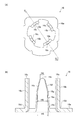
- FIG. 2B is a cross-sectional view taken along the line FF in FIG. 2A and 2B are views showing an inner yoke shown in FIG. 1, in which FIG. 1A is a plan view
- FIG. 1A is a plan view
- FIG. 1A is a plan view
- FIG. 1A is a plan view
- FIG. 1A is a plan view
- FIG. 1A It is a figure for demonstrating the arrangement
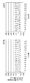
- (A) is a graph which shows the result of the simulation which calculates the torque and torque ripple of a motor when the distance of the width reduction rate change part shown in FIG. 5 and a front-end
- (B) is (A). ) Of the original data of the graph. It is a figure for demonstrating the structure of the pole tooth
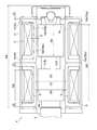
- FIG. 1 is a cross-sectional view of a stepping motor 1 according to an embodiment of the present invention.
- FIG. 2 is a diagram showing the stepping motor 1 from the EE direction of FIG. 3A and 3B are views showing the outer yoke 14 shown in FIG. 1, in which FIG. 3A is a plan view and FIG. 3B is a cross-sectional view taken along the line FF in FIG. 4A and 4B are diagrams showing the inner yoke 16 shown in FIG. 1, in which FIG. 4A is a plan view and FIG. 4B is a cross-sectional view taken along the line GG of FIG.
- the stepping motor 1 of this embodiment (hereinafter referred to as “motor 1”) is a so-called PM type stepping motor.
- the motor 1 includes a rotor 4 having a rotating shaft 2 and two drive magnets 3, and two drive coils 5 arranged on the outer peripheral side of the drive magnet 3. And a stator 6.
- the motor 1 holds a bearing (not shown) that supports an output side end (not shown) of the rotating shaft 2, a bearing 7 that supports a non-output side end of the rotating shaft 2, and the bearing 7.
- a leaf spring 9 for biasing the rotary shaft 2 to the output side.
- FIG. 1 the left side of FIG. 1 that is the output side of the rotary shaft 2 is referred to as “output side”, and the right side of FIG. Further, the left-right direction in FIG. 1, which is the axial direction of the rotating shaft 2, is referred to as “axial direction”, the direction orthogonal to the axial direction is “radial direction”, and the circumferential direction of the rotor 4 is “circumferential direction”.
- Rotating shaft 2 is made of a metal such as stainless steel, aluminum or brass.
- the output side of the rotating shaft 2 protrudes from the stator 6, and a lead screw 2 a is formed at a portion protruding from the stator 6.
- the lead screw 2a is screwed with a moving body such as an optical pickup device to move the moving body.
- the driving magnet 3 is a permanent magnet and is formed in a substantially cylindrical shape.
- the two drive magnets 3 are fixed to the non-output side of the rotary shaft 2 with a predetermined interval in the axial direction.
- the two drive magnets 3 are arranged substantially symmetrically with respect to the plane P passing through the approximate center of the stator 6 in the axial direction.
- N poles and S poles are alternately formed along the circumferential direction.
- the width in the circumferential direction of N poles and S poles alternately formed on the outer peripheral surface of the drive magnet 3 is, for example, an arrangement pitch in the circumferential direction of pole teeth 14b and 16b described later arranged alternately in the circumferential direction. It is almost equal to.
- the stator 6 includes a first stator part set 12 and a second stator part set 13.
- the first stator part set 12 and the second stator part set 13 are arranged so as to overlap in the axial direction.
- the first stator part set 12 includes an outer yoke 14, a bobbin 15 around which one driving coil 5 is wound, and an inner yoke 16 disposed so as to sandwich the bobbin 15 between the outer yoke 14 and And a case member 17 that covers each of these components from the radially outer side and the non-output side.
- the first stator part set 12 is arranged on the outer side in the radial direction of the driving magnet 3 arranged on the non-output side.
- the bobbin 15 is formed in a cylindrical shape with a flange having flange portions 15a and 15b at both ends in the axial direction.
- the thickness (axial thickness) of the flange portion 15a disposed on the output side is thinner than the thickness of the flange portion 15b disposed on the non-output side.
- the driving coil 5 is wound around the outer periphery of the bobbin 15. That is, the driving coil 5 is wound in a cylindrical shape such as a cylindrical shape.
- the outer yoke 14 has an end plate portion 14a formed in a substantially annular shape, and is formed so as to stand in the axial direction from the inner peripheral end of the end plate portion 14a. And a plurality of pole teeth 14b arranged at a pitch.
- the inner yoke 16 has an end plate portion 16a formed in a substantially annular shape, and is formed so as to stand in the axial direction from the inner peripheral end of the end plate portion 16a and has a predetermined pitch in the circumferential direction. And a plurality of pole teeth 16b.
- the outer yoke 14 includes four pole teeth 14b, and the four pole teeth 14b are arranged at a substantially 90 ° pitch.
- the inner yoke 16 includes four pole teeth 16b, and the four pole teeth 16b are arranged at a pitch of approximately 90 °.
- the end plate portion 14 a of the outer yoke 14 is arranged so as to cover the end surface on the opposite side of the driving coil 5, and the end plate portion 16 a of the inner yoke 16 covers the output side end surface of the driving coil 5.
- the driving coil 5 is sandwiched between the end plate portion 14a and the end plate portion 16a in the axial direction.
- the end plate portion 14a is arranged so as to cover the surface on the opposite side of the flange portion 15a of the bobbin 15, and the end plate portion 16a covers the output side surface of the flange portion 15b of the bobbin 15.
- the bobbin 15 is sandwiched between the end plate portion 14a and the end plate portion 16a in the axial direction.
- the pole teeth 14b and 16b are arranged so as to face the outer peripheral surface of the drive magnet 3.
- the pole teeth 14b and the pole teeth 16b are alternately arranged so as to be adjacent in the circumferential direction. That is, the pole teeth 14b are inserted between the four pole teeth 14b from the output side, and the pole teeth 14b are inserted between the four pole teeth 16b from the counter-output side. And pole teeth 16b are arranged.
- a bobbin 15 around which the drive coil 5 is wound is disposed on the radially outer side of the pole teeth 14b and 16b.
- the second stator part set 13 is configured by arranging the same configuration as the first stator part set 12 symmetrically with respect to the plane P passing through the approximate center of the stator 6 in the axial direction. That is, the second stator section set 13 is similar to the first stator section set 12 in that the outer yoke 14, the bobbin 15 around which one driving coil 5 is wound, the inner yoke 16, and the case member 17, and as shown in FIG. 1, the output side surface of the end plate portion 16 a of the inner yoke 16 constituting the first stator portion set 12 and the inner portion constituting the second stator portion set 13. The surface of the end plate portion 16a of the yoke 16 on the side opposite to the output side is in contact with the plane P. Therefore, a detailed description of the configuration of the second stator unit set 13 is omitted.
- the bearing holding member 8 is formed in a substantially cylindrical shape, and is fixed to the end face on the non-output side of the first stator set 12. That is, the bearing holding member 8 is fixed to the end face on the opposite side of the case member 17 of the first stator part set 12.
- the bearing 7 is held on the inner peripheral side of the bearing holding member 8 and is movable in the axial direction.
- the bearing 7 is formed with a recess in which the spherical pivot 19 is disposed. Further, a concave portion in which the pivot 19 is disposed is also formed on the end surface of the rotating shaft 2 on the opposite side to the output side.
- the leaf spring 9 is fixed to the non-output side of the bearing holding member 8. As shown in FIG. 2, a spring portion 9 a that contacts the bearing 7 is formed at the center of the plate spring 9. The spring portion 9 a biases the rotary shaft 2 to the output side via the bearing 7 and the pivot 19.
- the bearing 7, the bearing holding member 8, the leaf spring 9 and the pivot 19 support the counter-output side end of the rotor 4 in the radial direction and the thrust direction.
- a part of the output end side of the bearing 7 urged by the spring portion 9a is more than the end face on the counter-output side of the case member 17 of the first stator assembly 12 as shown in FIG. Is also arranged on the output side. That is, a part on the output end side of the bearing 7 is disposed inside the stator 6.
- the shape is substantially oval as shown in FIG.
- the shape is substantially oval formed by two arcs having the same radius of curvature and the center of curvature and two lines parallel to the vertical direction in FIG. It has become. Therefore, compared with a motor having a circular shape when viewed from the axial direction, the motor 1 can be downsized in the left-right direction in FIG. 2 in this embodiment.
- the outer diameter ⁇ of the motor 1 is 7.5 mm
- the width W0 of the motor 1 in the left-right direction in FIG. 2 is 6 mm.
- the driving coil 5 is covered with the case member 17 also on the left and right side surfaces of FIG. That is, the driving coil 5 is covered with the case member 17 over the entire circumference.
- the outer yoke 14 includes the end plate portion 14a and the four pole teeth 14b. As shown in FIG. 3B, the tip portion 14c of the pole tooth 14b is formed in a convex curved surface shape. Specifically, the distal end portion 14c is formed in a convex curved surface shape that has a substantially arc shape when viewed from the radial direction.
- the pole teeth 14b move from the base end portion 14d of the pole teeth 14b formed at the boundary portion between the end plate portion 14a and the pole teeth 14b toward the tip end portion 14c.
- the width (specifically, the width in the circumferential direction) is formed to be narrow. Specifically, from the base end portion 14d to the tip end portion 14c, the width of the pole teeth 14b decreases very slowly at first, and then the width of the pole teeth 14b decreases gradually.
- the shape when viewed from the radial direction is substantially pentagonal or hexagonal.
- the pole teeth 14b of the present embodiment are arranged on the base end side of the pole teeth 14b, and the width reduction rate of the pole teeth 14b decreases at a predetermined reduction rate toward the tip end side of the pole teeth 14b.
- the portion 14e is arranged at the distal end side of the pole tooth 14b, and the width of the pole tooth 14b is reduced at a larger reduction rate than the small width reduction rate portion 14e toward the tip end side of the pole tooth 14b. 14f.
- the boundary between the small width reduction rate portion 14e and the large reduction rate portion 14f is a width reduction rate changing portion 14g in which the width reduction rate of the pole teeth 14b changes.
- the small width decreasing rate portion 14e is formed so that the width of the pole teeth 14b is reduced by the same amount from both sides in the circumferential direction as it goes toward the tip end side of the pole teeth 14b. Further, both end portions in the circumferential direction of the small width reduction rate portion 14e are formed so that the shape when viewed from the radial direction is a straight line inclined with respect to the axial direction (vertical direction in FIG. 3B). In the small width reduction rate portion 14e, the width of the pole teeth 14b is gradually narrowed toward the tip side of the pole teeth 14b.
- the drastic reduction rate portion 14f is formed such that the width of the pole teeth 14b is reduced by the same amount from both sides in the circumferential direction as it goes toward the tip end side of the pole teeth 14b. Further, both end portions in the circumferential direction of the significant decrease rate portion 14f are formed so that the shape when viewed from the radial direction is a straight line inclined with respect to the axial direction. The width of the pole teeth 14b is gradually narrowed toward the tip end side of 14b.
- the inclination with respect to the axial direction of both ends in the circumferential direction of the large decrease rate portion 14f when viewed from the radial direction is larger than the inclination with respect to the axial direction of both ends in the circumferential direction of the small width decreasing rate portion 14e when viewed from the radial direction. It is getting bigger.
- the inner yoke 16 includes the end plate portion 16a and the four pole teeth 16b.
- the pole teeth 16 b are formed in the same shape as the pole teeth 14 b of the outer yoke 14. That is, first, as shown in FIG. 4B, the tip 16c of the pole tooth 16b is formed in a convex curved surface having a substantially arc shape when viewed from the radial direction.
- the pole teeth 16b are arranged as they go from the base end portion 16d of the pole teeth 16b formed at the boundary portion between the end plate portion 16a and the pole teeth 16b toward the tip end portion 16c.
- the width is formed to be narrow. Specifically, from the base end portion 16d toward the tip end portion 16c, the width of the pole teeth 16b is decreased very slowly at first, and then the width of the pole teeth 16b is gradually decreased.
- the shape when viewed from the radial direction is substantially pentagonal or hexagonal.
- the pole teeth 16b are arranged on the base end side of the pole teeth 16b and the width reduction rate portion 16e in which the width of the pole teeth 16b decreases at a predetermined decrease rate toward the tip end side of the pole teeth 16b.
- a boundary portion between the small width reduction rate portion 16e and the large reduction rate portion 16f is a width reduction rate changing portion 16g in which the width reduction rate of the pole teeth 16b is changed.
- the narrow width decreasing rate portion 16e is formed so that the width of the pole teeth 16b is narrowed by the same amount from both sides in the circumferential direction toward the tip side of the pole teeth 16b. Further, both end portions in the circumferential direction of the small width reduction rate portion 16e are formed so that the shape when viewed from the radial direction is a straight line inclined with respect to the axial direction (vertical direction in FIG. 4B). .
- the large decrease rate portion 16f is formed such that the width of the pole teeth 16b is reduced by the same amount from both sides in the circumferential direction toward the tip end side of the pole teeth 16b. Further, both end portions in the circumferential direction of the significant decrease rate portion 16f are formed so that the shape when viewed from the radial direction is a straight line inclined with respect to the axial direction. Moreover, the inclination with respect to the axial direction of both ends in the circumferential direction of the large reduction rate portion 16f when viewed from the radial direction is larger than the inclination with respect to the axial direction of both ends in the circumferential direction of the small width reduction rate portion 16e when viewed from the radial direction. It is getting bigger.
- the width H1 of the distal end portion 14c of the pole tooth 14b is substantially 3 of the width H2 of the proximal end portion 14d of the pole tooth 14b. Further, the width H1 of the tip portion 14c is approximately 19/50 of the width H3 of the width reduction rate changing portion 14g of the pole teeth 14b. Similarly, in this embodiment, the width H4 of the distal end portion 16c of the pole tooth 16b is substantially 1 / of the width H5 of the proximal end portion 16d of the pole tooth 16b. Further, the width H4 of the tip portion 16c is approximately 19/50 of the width H6 of the width reduction rate changing portion 16g of the pole teeth 16b.
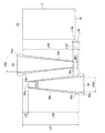
- FIG. 5 is a diagram for explaining the positional relationship between the driving magnet 3 and the pole teeth 14b and 16b shown in FIG.
- the pole teeth 14b of the outer yoke 14 and the pole teeth 16b of the inner yoke 16 are formed in the same shape. Therefore, in this embodiment, as shown in FIG. 5, the distance L1 between the base end portion 14d of the pole tooth 14b and the tip end portion 16c of the pole tooth 16b, and the tip end portion of the base end portion 16d of the pole tooth 16b and the pole tooth 14b. The distance L2 with respect to 14c is equal. Further, the distance L3 between the width reduction rate changing portion 16g of the pole tooth 16b and the base end portion 14d is equal to the distance L4 between the width reduction rate changing portion 14g of the pole tooth 14b and the base end portion 16d.
- the outer yoke 14 and the inner yoke 16 are arranged substantially symmetrically with respect to the plane P1 passing through the center of the driving magnet 3 in the axial direction.
- the pole teeth 14b and the pole teeth 16b are arranged substantially symmetrically with respect to the plane P1, and the distance L5 between the one end surface 3a and the base end portion 14d of the drive magnet 3 in the axial direction and the axial direction The distance L6 between the other end surface 3b of the driving magnet 3 and the base end portion 16d in FIG.
- the distance L7 between the one end surface 3a of the driving magnet 3 and the tip portion 16c and the distance L8 between the other end surface 3b of the driving magnet 3 and the tip portion 14c are substantially equal.
- the outer yoke 14 and the inner yoke 16 are arranged substantially symmetrically with respect to the plane P1, the center position CL1 between the base end portion 14d and the base end portion 16d in the axial direction and the plane P1 in the axial direction. Is substantially coincident with the position of. In FIG. 5, the center position CL1 and the plane P1 coincide with each other in the axial direction. However, the center position CL1 and the plane P1 may be slightly shifted in the axial direction.
- the one end surface 3a of the driving magnet 3 is disposed between the base end portion 14d and the distal end portion 16c in the axial direction, and the other end surface 3b of the driving magnet 3 is axially disposed.
- the base end portion 16d is disposed between the front end portion 14c.
- the distance L5 between the one end surface 3a of the driving magnet 3 and the base end portion 14d is shorter than the distance L7 between the one end surface 3a of the driving magnet 3 and the distal end portion 16c.
- the distance L6 between the other end surface 3b of the driving magnet 3 and the base end portion 16d is shorter than the distance L8 between the other end surface 3b of the driving magnet 3 and the distal end portion 14c.
- the width reduction rate changing portion 14g and the width reduction rate changing portion 16g are arranged at a substantially intermediate position between the tip portion 14c and the tip portion 16c in the axial direction.
- the width reduction rate changing portion 14g and the width reduction rate changing portion 16g are disposed at a substantially intermediate position between the base end portion 14d and the base end portion 16d in the axial direction.
- the width reduction rate changing part 14g is arranged on the base end part 14d side of the pole tooth 14b with respect to the center position CL1
- the width reduction rate changing part 16g is pole teeth with respect to the center position CL1. It is arranged on the base end portion 16d side of 16b.
- the width reduction rate changing portion 14g is disposed closer to the tip portion 14c side (center position CL1 side) of the pole tooth 14b than the center position CL2 between the center position CL1 and the tip portion 16c in the axial direction.
- the reduction rate changing portion 16g is disposed closer to the distal end portion 16c side (center position CL1 side) of the pole tooth 16b than the central position CL3 between the central position CL1 and the distal end portion 14c in the axial direction.
- the clearance in the circumferential direction is narrower than other portions. That is, in the region between the width reduction rate changing portion 14g and the width reduction rate changing portion 16g in the axial direction, the gap in the circumferential direction between the pole teeth 14b and the pole teeth 16b adjacent to each other in the circumferential direction is larger than that in other locations.
- the narrow gap portion R becomes narrower.
- the narrow gap portion R is formed at a substantially intermediate position between the tip portion 14c and the tip portion 16c in the axial direction. That is, the narrow gap portion R is formed at a substantially intermediate position between the base end portion 14d and the base end portion 16d in the axial direction.
- the distance between the narrow gap portion R and the distal end portion 16c in the axial direction is approximately 2/3 of the distance between the narrow gap portion R and the proximal end portion 14d in the axial direction, and the narrow gap portion R in the axial direction.
- the distal end portion 14c is approximately 2/3 of the distance between the narrow gap portion R and the proximal end portion 16d in the axial direction. More specifically, as shown in FIG. 5, in this embodiment, the distance L9 between the width reduction rate changing portion 16g and the distal end portion 16c in the axial direction is equal to the width reduction rate changing portion 16g and the proximal end portion 14d in the axial direction.
- the distance L10 between the width reduction rate changing portion 14g and the distal end portion 14c in the axial direction is the distance between the width reduction rate changing portion 14g and the proximal end portion 16d in the axial direction. It is approximately 2/3 of L4.
- the outer yoke 14 is a first yoke and the inner yoke 16 is a second yoke.
- the end plate portion 14a is a first end plate portion
- the end plate portion 16a is a second end plate portion
- the pole teeth 14b are first pole teeth
- the pole teeth 16b are second pole plates. Teeth.
- the distal end portion 14c is a first distal end portion
- the distal end portion 16c is a second distal end portion
- the proximal end portion 14d is a first proximal end portion
- the proximal end portion 16d is a second proximal end portion.
- the narrow width decrease rate portion 14e is a first narrow width decrease rate portion
- the narrow width decrease rate portion 16e is a second narrow width decrease rate portion
- the large decrease rate portion 14f is a first large decrease rate portion.
- the significant decrease rate unit 16f is a second significant decrease rate unit
- the width decrease rate change unit 14g is a first width decrease rate change unit
- the width decrease rate change unit 16g is a second width decrease rate change unit. is there.
- the center position CL1 is the first center position
- the center position CL2 is the second center position
- the center position CL3 is the third center position.
- the distance between the narrow gap portion R and the distal end portion 16c in the axial direction is approximately 2/3 of the distance between the narrow gap portion R and the base end portion 14d in the axial direction.
- the distance between the narrow gap portion R and the distal end portion 14c in the axial direction is approximately 2/3 of the distance between the narrow gap portion R and the proximal end portion 16d in the axial direction.
- the distance L9 between the width reduction rate changing portion 16g and the distal end portion 16c is approximately 2/3 of the distance L3 between the width reduction rate changing portion 16g and the base end portion 14d.
- the distance L10 between the width reduction rate changing portion 14g and the distal end portion 14c is approximately 2/3 of the distance L4 between the width reduction rate changing portion 14g and the base end portion 16d.
- the distance L1 between the proximal end portion 14d and the distal end portion 16c and the distance L2 between the proximal end portion 16d and the distal end portion 14c are compared while ensuring the facing area between the pole teeth 14b and 16b and the driving magnet 3. It becomes possible to make it larger. Therefore, the distance L5 from the one end surface 3a to the base end portion 14d of the driving magnet 3 and the one end surface 3a to the tip end portion of the driving magnet 3 are secured while ensuring the facing area between the pole teeth 14b and 16b and the driving magnet 3.
- the outer yoke 14, the inner yoke 16 (that is, the end plate portions 14a and 16a and the pole teeth 14b and 16b), the case member 17 and the like are thinned, and the pole teeth 14b and 16b are opposed to the driving magnet 3. Even if the area is secured, it is possible to suppress magnetic saturation at the locations where the magnetic fluxes of the distal end portions 14c and 16c and the proximal end portions 14d and 16d are concentrated. That is, in this embodiment, the outer yoke 14, the inner yoke 16, the case member 17 and the like are thinned to increase the number of turns of the driving coil 5, or the opposing area between the pole teeth 14b and 16b and the driving magnet 3 is secured.
- the pole teeth 14b are constituted by a small width reduction rate portion 14e and a large reduction rate portion 14f
- the pole teeth 16b are constituted by a small width reduction rate portion 16e and a large reduction rate portion 16f. Therefore, compared with the case where the width
- the narrow gap portion R is formed at a substantially intermediate position between the tip portion 14c and the tip portion 16c in the axial direction. That is, the narrow gap portion R is formed at a substantially intermediate position in the axial direction of the driving magnet 3 where the magnetic flux density is relatively high. For this reason, the gap in the circumferential direction between the pole teeth 14b and the pole teeth 16b can be narrowed at a substantially intermediate position in the axial direction of the drive magnet 3 where the magnetic flux density is relatively high, effectively reducing torque characteristics. It becomes possible to suppress.
- the pole teeth 14b and the pole teeth 16b are arranged substantially symmetrically with respect to the plane P1 passing through the center of the drive magnet 3 in the axial direction. Therefore, compared to the case where the pole teeth 14b and the pole teeth 16b are arranged asymmetrically with respect to the plane P1, it is possible to effectively reduce the torque ripple, and effectively reduce the linearity characteristics. It becomes possible to suppress.
- the width reduction rate changing part 14g is arranged on the base end part 14d side with respect to the center position CL1, and the width reduction rate changing part 16g is arranged on the base end part 16d side with respect to the center position CL1. Therefore, compared with the case where the width reduction rate changing portion 14g is arranged on the distal end portion 14c side with respect to the center position CL1, it is possible to suppress magnetic saturation at the location where the magnetic flux of the proximal end portion 14d is concentrated. Become. Further, compared to the case where the width reduction rate changing portion 16g is arranged on the distal end portion 16c side with respect to the center position CL1, it is possible to suppress magnetic saturation at a location where the magnetic flux of the proximal end portion 16d is concentrated. Become.
- the magnetic fluxes at the base end portions 14d and 16d are concentrated. It is possible to suppress the magnetic saturation at the place to be performed and to suppress the deterioration of the linearity characteristic.
- the width reduction rate changing part 14g is arranged on the tip part 14c side with respect to the center position CL2, and the width reduction rate changing part 16g is arranged on the tip part 16c side with respect to the center position CL3. Therefore, even when the width reduction rate changing part 14g is arranged on the base end part 14d side from the center position CL1, and the width reduction rate changing part 16g is arranged on the base end part 16d side from the center position CL1. Thus, it is possible to secure a facing area between the pole teeth 14b and 16b and the driving magnet 3 and suppress a decrease in torque.
- the one end surface 3a of the driving magnet 3 is disposed between the proximal end portion 14d and the distal end portion 16c in the axial direction, and the other end surface 3b of the driving magnet 3 is proximal in the axial direction. It is arrange
- the outer yoke 14, the inner yoke 16, the case member 17 and the like are thinned to increase the number of turns of the driving coil 5 and suppress a decrease in torque.
- the tip portions 14c and 16c are formed in a convex curved surface shape. Therefore, even if the tip portions 14c and 16c are relatively close to the one end surface 3a or the other end surface 3b of the driving magnet 3, it is possible to suppress the magnetic flux from concentrating on the tip portions 14c and 16c. That is, it is possible to suppress the magnetic flux from concentrating on the tip portions 14c and 16c while increasing the facing area between the pole teeth 14b and 16b and the driving magnet 3. Therefore, it is possible to form an efficient magnetic circuit while suppressing the magnetic flux from concentrating on the tip portions 14c and 16c, and it is possible to efficiently suppress a decrease in torque.
- the distance L5 between the one end surface 3a of the driving magnet 3 and the base end portion 14d is shorter than the distance L7 between the one end surface 3a of the driving magnet 3 and the distal end portion 16c.
- the distance L6 between the other end surface 3b of the driving magnet 3 and the base end portion 16d is shorter than the distance L8 between the other end surface 3b of the driving magnet 3 and the distal end portion 14c. Therefore, compared with the case where the distance L5 is longer than the distance L7 and the distance L6 is longer than the distance L8, the length of the driving magnet 3 in the axial direction is constant, and the distances L7 and L8 are constant. In this case, the length of the pole teeth 14b and 16b in the axial direction can be shortened. Therefore, when the length of the drive magnet 3 in the axial direction is constant and the distances L7 and L8 are constant, the motor 1 can be downsized in the axial direction.
- (Simulation 1) 6 shows the torque and torque ripple of the motor 1 when the distance L9 between the width reduction rate changing portion 16g and the tip portion 16c and the distance L10 between the width reduction rate changing portion 14g and the tip portion 14c shown in FIG. 5 are changed. It is a figure for demonstrating the conditions of the simulation which computes.
- 7A shows the torque of the motor 1 when the distance L9 between the width reduction rate changing portion 16g and the tip portion 16c and the distance L10 between the width reduction rate changing portion 14g and the tip portion 14c shown in FIG. 5 are changed.
- FIG. 7B is a list of original data of the graph of FIG. 7A.
- the axial length W1 of the drive magnet 3 (see FIG. 6), the distance L11 (see FIG. 5) between the proximal end portion 14d of the pole tooth 14b and the proximal end portion 16d of the pole tooth 16b in the axial direction, and the axial direction
- the distance L12 (see FIG. 5) between the base end portion 14d and the width reduction rate changing portion 14g, the distance L13 (see FIG.
- Inner diameter D2 of pole teeth 14b and 16b 3.46 mm
- Outer diameter D3 of the pole teeth 14b and 16b 4.2 mm Gap S between the pole teeth 14b and 16b and the driving magnet 3 in the radial direction: 0.15 mm
- Motor 1 outer diameter ⁇ 7.5 mm
- Motor 1 width W0 6 mm
- L14 shown in FIG. 5 is the distance from the distal end portion 14c to the proximal end portion 14d of the pole tooth 14b (that is, the axial length of the pole tooth 14b)
- L15 shown in FIG. 5 is the pole tooth 16b. The distance from the distal end portion 16c to the proximal end portion 16d (that is, the axial length of the pole teeth 16b).
- Figure 7 shows the result of simulation under the above conditions.
- Condition 1 where the distances L9 and L10 are 1.2 mm, the torque ripple is small and the linearity characteristic is good, but the torque is small and the torque characteristic is not good.
- condition 3 where the distances L9 and L10 were 1.96 mm and in the case of condition 4 where the distances L9 and L10 were 2.2 mm, the torque was large and the torque characteristics were good. The torque ripple was large and the linearity characteristics were not good.
- Condition 2 where the distances L9 and L10 were 1.6 mm, the torque ripple was small, the torque was large, and both the linearity characteristics and the torque characteristics were good.
- the distances L9 and L10 are 1.6 mm
- the distances L3 and L4 are 2.41 mm
- the distances L9 and L10 are approximately 2/3 of the distances L3 and L4
- the linearity characteristic and the torque characteristic are Good balance.
- the distances L9 and L10 are approximately 2/3 of the distances L3 and L4, the facing area between the pole teeth 14b and 16b and the driving magnet 3 is secured, and the torque characteristics are reduced.
- FIG. 8 is a diagram for explaining the configuration and arrangement relationship of the pole teeth 54b and 56b of the motor according to the comparative example, and the arrangement relationship between the drive magnet 3 and the pole teeth 54b and 56b.
- FIG. 9 is a graph showing the results of a simulation for calculating the torque of the motor 1 shown in FIG. 1 and the torque of the motor according to the comparative example.
- FIG. 10 is a graph showing the results of a simulation for calculating the torque ripple of the motor 1 shown in FIG. 1 and the torque ripple of the motor according to the comparative example.
- the simulation conditions will be described.
- the motor 1 set in the condition 2 of the simulation 1 described above was used as the motor 1 according to the example.
- the motor according to the comparative example as shown in FIG. 8, a motor in which the circumferential clearance between the pole teeth 54b of the outer yoke 54 and the pole teeth 56b of the inner yoke 56 is constant in the axial direction is used. did.
- each dimension shown to FIG. 6, FIG. 8 of the motor concerning a comparative example was set as follows. Except for the shapes of the pole teeth 54b and 56b and the following set values, the motor according to the comparative example and the motor 1 are configured in substantially the same manner.
- the pole teeth 54b and the pole teeth 56b are formed in the same shape.
- the tip 54c of the pole tooth 54b and the tip 56c of the pole tooth 56b are formed in a planar shape.
- the pull-out torque (POT) which is a torque for stopping the rotating rotor 4 is almost the same between the motor 1 according to the embodiment and the motor according to the comparative example.
- the pull-in torque (PIT) which is a torque for starting the stopped rotor 4 is also substantially the same in the motor 1 according to the embodiment and the motor according to the comparative example.
- the torque ripple of the motor 1 according to the example and the torque ripple of the motor according to the comparative example are substantially equal.
- the motor 1 in which the distances L9 and L10 are approximately 2/3 of the distances L3 and L4 is shorter by 2 mm in the axial direction than the motor according to the comparative example (that is, smaller by 2 mm in the axial direction).
- the motor according to the comparative example that is, smaller by 2 mm in the axial direction.
- the torque characteristics can be prevented from deteriorating, and magnetic saturation at the locations where the magnetic fluxes of the tip end portions 14c and 16c and the base end portions 14d and 16d are concentrated is suppressed, and the linearity characteristics are lowered. Can be suppressed.
- a part of the output end side of the bearing 7 is disposed inside the stator 6.
- the rotary shaft 2, the bearing 7, the bearing holding member 8, and the leaf spring 9 may be configured so that most of the bearing 7 is disposed inside the stator 6.
- the rotary shaft 2, the bearing 7, the bearing holding member 8, and the leaf spring 9 are arranged so that the entire bearing 7 is disposed inside the stator 6 (that is, the bearing 7 is accommodated inside the stator 6). May be configured.
- the stator 6 is constituted by the first stator part set 12 and the second stator part set 13.
- the stator 6 may be constituted by three or more stator part sets.
- the shape of the motor 1 when viewed from the axial direction is a substantially oval shape.
- the shape of the motor 1 when viewed from the axial direction may be a substantially circular shape.
Landscapes
- Engineering & Computer Science (AREA)
- Power Engineering (AREA)
- Iron Core Of Rotating Electric Machines (AREA)
Abstract
Description
3 駆動用磁石
3a 一端面
3b 他端面
4 ロータ
5 駆動用コイル
6 ステータ
12 第1のステータ部組(ステータ部組)
13 第2のステータ部組(ステータ部組)
14 外ヨーク(第1のヨーク)
14a 端板部(第1の端板部)
14b 極歯(第1の極歯)
14c 先端部(第1の先端部)
14d 基端部(第1の基端部)
14e 小幅減少率部(第1の小幅減少率部)
14f 大幅減少率部(第1の大幅減少率部)
14g 幅減少率変更部(第1の幅減少率変更部)
16 内ヨーク(第2のヨーク)
16a 端板部(第2の端板部)
16b 極歯(第2の極歯)
16c 先端部(第2の先端部)
16d 基端部(第2の基端部)
16e 小幅減少率部(第2の小幅減少率部)
16f 大幅減少率部(第2の大幅減少率部)
16g 幅減少率変更部(第2の幅減少率変更部)
CL1 中心位置(第1の中心位置)
CL2 中心位置(第2の中心位置)
CL3 中心位置(第3の中心位置)
L1 第1の基端部と第2の先端部との距離
L2 第2の基端部と第1の先端部との距離
L3 第2の幅減少率変更部と第1の基端部
L4 第1の幅減少率変更部と第2の基端部との距離
L5 駆動用磁石の一端面と第1の基端部との距離
L6 駆動用磁石の他端面と第2の基端部との距離
L7 駆動用磁石の一端面と第2の先端部との距離
L8 駆動用磁石の他端面と第1の先端部との距離
L9 第2の幅減少率変更部と第2の先端部との距離
L10 第1の幅減少率変更部と第1の先端部との距離
R 狭隙間部
図1は、本発明の実施の形態にかかるステッピングモータ1の断面図である。図2は、図1のE-E方向からステッピングモータ1を示す図である。図3は、図1に示す外ヨーク14を示す図であり、(A)は平面図、(B)は(A)のF-F断面の断面図である。図4は、図1に示す内ヨーク16を示す図であり、(A)は平面図、(B)は(A)のG-G断面の断面図である。
上述のように、外ヨーク14は、端板部14aと、4個の極歯14bとを備えている。図3(B)に示すように、極歯14bの先端部14cは、凸曲面状に形成されている。具体的には、先端部14cは、径方向から見たときの形状が略1/4円弧状になる凸曲面状に形成されている。
図5は、図1に示す駆動用磁石3および極歯14b、16bの配置関係を説明するための図である。
以上説明したように、本形態では、軸方向における狭隙間部Rと先端部16cとの距離は、軸方向における狭隙間部Rと基端部14dとの距離の略2/3となっており、軸方向における狭隙間部Rと先端部14cとの距離は、軸方向における狭隙間部Rと基端部16dとの距離の略2/3となっている。より具体的には、本形態では、幅減少率変更部16gと先端部16cとの距離L9は、幅減少率変更部16gと基端部14dとの距離L3の略2/3となっており、幅減少率変更部14gと先端部14cとの距離L10は、幅減少率変更部14gと基端部16dとの距離L4の略2/3となっている。
図6は、図5に示す幅減少率変更部16gと先端部16cとの距離L9および幅減少率変更部14gと先端部14cとの距離L10を変化させたときのモータ1のトルクおよびトルクリップルを算出するシミュレーションの条件を説明するための図である。図7(A)は、図5に示す幅減少率変更部16gと先端部16cとの距離L9および幅減少率変更部14gと先端部14cとの距離L10を変化させたときのモータ1のトルクおよびトルクリップルを算出するシミュレーションの結果を示すグラフであり、図7(B)は図7(A)のグラフの元データの一覧表である。
距離L5:0.26mm
距離L6:0.3mm
距離L11:4.41mm
距離L12、L13:2mm
先端部14cの幅H1、先端部16cの幅H4:0.457mm
基端部14dの幅H2、基端部16dの幅H5:1.339mm
幅減少率変更部14gの幅H3、幅減少率変更部16gの幅H6:1.2mm
先端部14c、16cの曲率半径:0.4mm
駆動用磁石3の長さW1:3.85mm
駆動用コイル5の軸方向の長さW2:3.7mm
2個の駆動用磁石3の一端面3a間の距離W3:9.2mm
ステータ6の出力側端からモータ1の反出力側端までの距離W4:12.42mm
極歯14b、16bの厚さt1:0.37mm
端板部14a、16aの厚さt2:0.45mm
ケース部材17の厚さt3:0.2mm
駆動用磁石3の外径D1:3.16mm
極歯14b、16bの内径D2:3.46mm
極歯14b、16bの外径D3:4.2mm
径方向における極歯14b、16bと駆動用磁石3との隙間S:0.15mm
モータ1の外径φ:7.5mm
モータ1の幅W0:6mm
なお、図5に示すL14は、極歯14bの先端部14cから基端部14dまでの距離(すなわち、極歯14bの軸方向の長さ)であり、図5に示すL15は、極歯16bの先端部16cから基端部16dまでの距離(すなわち、極歯16bの軸方向の長さ)である。
図8は、比較例にかかるモータの極歯54b、56bの構成、配置関係、および、駆動用磁石3と極歯54b、56bとの配置関係を説明するための図である。図9は、図1に示すモータ1のトルクと比較例にかかるモータのトルクとを算出するシミュレーションの結果を示すグラフである。図10は、図1に示すモータ1のトルクリップルと比較例にかかるモータのトルクリップルとを算出するシミュレーションの結果を示すグラフである。
極歯56bの基端部56dと極歯54bの先端部54cとの距離L52:0.5mm
駆動用磁石3の一端面3aと基端部54dとの距離:0mm
駆動用磁石3の他端面3bと基端部56dとの距離L56:0.3mm
駆動用磁石3の他端面3bと先端部54cとの距離L58:0.2mm
基端部54dと基端部56dとの距離L61:5.11mm
極歯54bの軸方向の長さL64、極歯56bの軸方向の長さL65:4.61mm
先端部54cの幅H51、先端部56cの幅H53:0.585mm
基端部54dの幅H52、基端部56dの幅H54:1.339mm
駆動用磁石3の長さW1:4.81mm
駆動用コイル5の軸方向の長さW2:4.3mm
2個の駆動用磁石3の一端面3a間の距離W3:11.22mm
ステータ6の出力側端からモータ1の反出力側端までの距離W4:14.42mm
極歯54b、56bの厚さt1:0.45mm
端板部54a、56aの厚さt2:0.5mm
ケース部材17の厚さt3:0.3mm
駆動用磁石3の外径D1:3.2mm
極歯54b、56bの内径D2:3.5mm
極歯54b、56bの外径D3:4.4mm
径方向における極歯54b、56bと駆動用磁石3との隙間S:0.15mm
上述した形態は、本発明の好適な形態の一例ではあるが、これに限定されるものではなく本発明の要旨を変更しない範囲において種々変形実施が可能である。
Claims (13)
- 駆動用磁石を有するロータと、筒状に巻回され前記駆動用磁石の外周側に配置される駆動用コイルを有するステータとを備え、
前記ステータは、前記ロータの軸方向における前記駆動用コイルの一端面を覆うように配置される略環状の第1の端板部を有する第1のヨークと、前記軸方向における前記駆動用コイルの他端面を覆うように配置される略環状の第2の端板部を有する第2のヨークとを備え、
前記第1のヨークは、前記第1の端板部の内周端から起立するように形成され前記駆動用磁石の外周面に対向するように配置される複数の第1の極歯を備え、
前記第2のヨークは、前記第2の端板部の内周端から起立するように形成され前記駆動用磁石の外周面に対向するように配置される複数の第2の極歯を備え、
前記第1の極歯と前記第2の極歯とは、前記ロータの周方向で交互に配置され、
前記周方向で互いに隣接する前記第1の極歯と前記第2の極歯との前記周方向における隙間が狭くなる狭隙間部が、前記第1の極歯の先端部である第1の先端部と前記第2の極歯の先端部である第2の先端部との前記軸方向における略中間位置に形成され、
前記軸方向における前記第1の先端部と前記狭隙間部との距離は、前記第2の端板部と前記第2の極歯との境界部に形成される前記第2の極歯の基端部である第2の基端部と前記狭隙間部との前記軸方向における距離の略2/3であり、
前記軸方向における前記第2の先端部と前記狭隙間部との距離は、前記第1の端板部と前記第1の極歯との境界部に形成される前記第1の極歯の基端部である第1の基端部と前記狭隙間部との前記軸方向における距離の略2/3であることを特徴とするステッピングモータ。 - 前記狭隙間部は、前記軸方向における前記第1の基端部と前記第2の基端部との略中間位置に形成され、
前記軸方向における前記駆動用磁石の一端面と前記第1の基端部との距離と、前記軸方向における前記駆動用磁石の他端面と前記第2の基端部との距離とが略等しいことを特徴とする請求項1記載のステッピングモータ。 - 駆動用磁石を有するロータと、筒状に巻回され前記駆動用磁石の外周側に配置される駆動用コイルを有するステータとを備え、
前記ステータは、前記ロータの軸方向における前記駆動用コイルの一端面を覆うように配置される略環状の第1の端板部を有する第1のヨークと、前記軸方向における前記駆動用コイルの他端面を覆うように配置される略環状の第2の端板部を有する第2のヨークとを備え、
前記第1のヨークは、前記第1の端板部の内周端から起立するように形成され前記駆動用磁石の外周面に対向するように配置される複数の第1の極歯を備え、
前記第2のヨークは、前記第2の端板部の内周端から起立するように形成され前記駆動用磁石の外周面に対向するように配置される複数の第2の極歯を備え、
前記第1の極歯と前記第2の極歯とは、前記ロータの周方向で交互に配置され、
前記第1の極歯は、前記第1の端板部と前記第1の極歯との境界部に形成される前記第1の極歯の基端部である第1の基端部から前記第1の極歯の先端部である第1の先端部に向かうにしたがってその幅が狭くなるように形成され、
前記第2の極歯は、前記第2の端板部と前記第2の極歯との境界部に形成される前記第2の極歯の基端部である第2の基端部から前記第2の極歯の先端部である第2の先端部に向かうにしたがってその幅が狭くなるように形成され、
前記第1の極歯は、その基端側に配置されるとともに前記第1の極歯の先端側に向かうにしたがって所定の減少率で前記第1の極歯の幅が減少していく第1の小幅減少率部と、前記第1の極歯の先端側に配置されるとともに前記第1の極歯の先端側に向かうにしたがって前記第1の小幅減少率部よりも大きな減少率で前記第1の極歯の幅が減少していく第1の大幅減少率部とから構成され、
前記第2の極歯は、その基端側に配置されるとともに前記第2の極歯の先端側に向かうにしたがって所定の減少率で前記第2の極歯の幅が減少していく第2の小幅減少率部と、前記第2の極歯の先端側に配置されるとともに前記第2の極歯の先端側に向かうにしたがって前記第2の小幅減少率部よりも大きな減少率で前記第2の極歯の幅が減少していく第2の大幅減少率部とから構成され、
前記第1の小幅減少率部と前記第1の大幅減少率部との境界部となる第1の幅減少率変更部、および、前記第2の小幅減少率部と前記第2の大幅減少率部との境界部となる第2の幅減少率変更部は、前記軸方向における前記第1の先端部と前記第2の先端部との略中間位置に配置され、
前記軸方向における前記第1の幅減少率変更部と前記第1の先端部との距離は、前記軸方向における前記第1の幅減少率変更部と前記第2の基端部との距離の略2/3であり、
前記軸方向における前記第2の幅減少率変更部と前記第2の先端部との距離は、前記軸方向における前記第2の幅減少率変更部と前記第1の基端部との距離の略2/3であることを特徴とするステッピングモータ。 - 前記第1の幅減少率変更部および前記第2の幅減少率変更部は、前記軸方向における前記第1の基端部と前記第2の基端部との略中間位置に配置され、
前記軸方向における前記駆動用磁石の一端面と前記第1の基端部との距離と、前記軸方向における前記駆動用磁石の他端面と前記第2の基端部との距離とが略等しいことを特徴とする請求項3記載のステッピングモータ。 - 駆動用磁石を有するロータと、筒状に巻回され前記駆動用磁石の外周側に配置される駆動用コイルを有するステータとを備え、
前記ステータは、前記ロータの軸方向における前記駆動用コイルの一端面を覆うように配置される略環状の第1の端板部を有する第1のヨークと、前記軸方向における前記駆動用コイルの他端面を覆うように配置される略環状の第2の端板部を有する第2のヨークとを備え、
前記第1のヨークは、前記第1の端板部の内周端から起立するように形成され前記駆動用磁石の外周面に対向するように配置される複数の第1の極歯を備え、
前記第2のヨークは、前記第2の端板部の内周端から起立するように形成され前記駆動用磁石の外周面に対向するように配置される複数の第2の極歯を備え、
前記第1の極歯と前記第2の極歯とは、前記ロータの周方向で交互に配置され、
前記第1の極歯は、前記第1の端板部と前記第1の極歯との境界部に形成される前記第1の極歯の基端部である第1の基端部から前記第1の極歯の先端部である第1の先端部に向かうにしたがってその幅が狭くなるように形成され、
前記第2の極歯は、前記第2の端板部と前記第2の極歯との境界部に形成される前記第2の極歯の基端部である第2の基端部から前記第2の極歯の先端部である第2の先端部に向かうにしたがってその幅が狭くなるように形成され、
前記第1の極歯は、その基端側に配置されるとともに前記第1の極歯の先端側に向かうにしたがって所定の減少率で前記第1の極歯の幅が減少していく第1の小幅減少率部と、前記第1の極歯の先端側に配置されるとともに前記第1の極歯の先端側に向かうにしたがって前記第1の小幅減少率部よりも大きな減少率で前記第1の極歯の幅が減少していく第1の大幅減少率部とから構成され、
前記第2の極歯は、その基端側に配置されるとともに前記第2の極歯の先端側に向かうにしたがって所定の減少率で前記第2の極歯の幅が減少していく第2の小幅減少率部と、前記第2の極歯の先端側に配置されるとともに前記第2の極歯の先端側に向かうにしたがって前記第2の小幅減少率部よりも大きな減少率で前記第2の極歯の幅が減少していく第2の大幅減少率部とから構成され、
前記第1の小幅減少率部と前記第1の大幅減少率部との境界部となる第1の幅減少率変更部は、前記軸方向における前記第1の基端部と前記第2の基端部との中心位置である第1の中心位置よりも前記第1の基端部側に配置され、
前記第2の小幅減少率部と前記第2の大幅減少率部との境界部となる第2の幅減少率変更部は、前記第1の中心位置よりも前記第2の基端部側に配置されていることを特徴とするステッピングモータ。 - 前記第1の幅減少率変更部は、前記軸方向における前記第1の中心位置と前記第2の先端部との中心位置である第2の中心位置よりも前記第1の先端部側に配置され、
前記第2の幅減少率変更部は、前記軸方向における前記第1の中心位置と前記第1の先端部との中心位置である第3の中心位置よりも前記第2の先端部側に配置されていることを特徴とする請求項5記載のステッピングモータ。 - 前記軸方向における前記第1の幅減少率変更部と前記第2の幅減少率変更部との間は、前記周方向で互いに隣接する前記第1の極歯と前記第2の極歯との前記周方向における隙間が狭くなる狭隙間部となっていることを特徴とする請求項5または6記載のステッピングモータ。
- 前記軸方向における前記第1の幅減少率変更部と前記第1の先端部との距離は、前記軸方向における前記第1の幅減少率変更部と前記第2の基端部との距離の略2/3であり、
前記軸方向における前記第2の幅減少率変更部と前記第2の先端部との距離は、前記軸方向における前記第2の幅減少率変更部と前記第1の基端部との距離の略2/3であることを特徴とする請求項5または6記載のステッピングモータ。 - 前記軸方向における前記第1の幅減少率変更部と前記第1の中心位置との距離と、前記軸方向における前記第2の幅減少率変更部と前記第1の中心位置との距離とが略等しく、
前記軸方向における前記駆動用磁石の一端面と前記第1の基端部との距離と、前記軸方向における前記駆動用磁石の他端面と前記第2の基端部との距離とが略等しいことを特徴とする請求項5または6記載のステッピングモータ。 - 前記軸方向における前記駆動用磁石の一端面は、前記軸方向において、前記第1の基端部と前記第2の先端部との間に配置され、
前記軸方向における前記駆動用磁石の他端面は、前記軸方向において、前記第2の基端部と前記第1の先端部との間に配置され、
前記第1の先端部および前記第2の先端部は、凸曲面状に形成されていることを特徴とする請求項5または6記載のステッピングモータ。 - 前記軸方向における前記駆動用磁石の一端面は、前記軸方向において、前記第1の基端部と前記第2の先端部との間に配置されるとともに、前記軸方向における前記駆動用磁石の一端面と前記第1の基端部との距離は、前記軸方向における前記駆動用磁石の一端面と前記第2の先端部との距離よりも短く、
前記軸方向における前記駆動用磁石の他端面は、前記軸方向において、前記第2の基端部と前記第1の先端部との間に配置されるとともに、前記軸方向における前記駆動用磁石の他端面と前記第2の基端部との距離は、前記軸方向における前記駆動用磁石の他端面と前記第1の先端部との距離よりも短いことを特徴とする請求項5または6記載のステッピングモータ。 - 前記軸方向における前記駆動用磁石の一端面は、前記軸方向において、前記第1の基端部と前記第2の先端部との間に配置され、
前記軸方向における前記駆動用磁石の他端面は、前記軸方向において、前記第2の基端部と前記第1の先端部との間に配置され、
前記軸方向における前記第1の基端部と前記第2の先端部との距離と、前記軸方向における前記第2の基端部と前記第1の先端部との距離とが略等しく、
前記軸方向における前記駆動用磁石の一端面と前記第1の基端部との距離と、前記軸方向における前記駆動用磁石の他端面と前記第2の基端部との距離とが略等しいことを特徴とする請求項5または6記載のステッピングモータ。 - 前記ステータは、前記駆動用コイルと前記第1のヨークと前記第2のヨークとを有するステータ部組を複数備え、
前記ステータ部組は、前記軸方向で重なるように配置されていることを特徴とする請求項1から6のいずれかに記載のステッピングモータ。
Priority Applications (3)
| Application Number | Priority Date | Filing Date | Title |
|---|---|---|---|
| CN201080001362.2A CN101990734B (zh) | 2009-03-18 | 2010-03-04 | 步进电动机 |
| JP2010527266A JP5185386B2 (ja) | 2009-03-18 | 2010-03-04 | ステッピングモータ |
| US12/916,865 US7977828B2 (en) | 2009-03-18 | 2010-11-01 | Stepping motor |
Applications Claiming Priority (2)
| Application Number | Priority Date | Filing Date | Title |
|---|---|---|---|
| JP2009-066371 | 2009-03-18 | ||
| JP2009066371 | 2009-03-18 |
Related Child Applications (1)
| Application Number | Title | Priority Date | Filing Date |
|---|---|---|---|
| US12/916,865 Continuation US7977828B2 (en) | 2009-03-18 | 2010-11-01 | Stepping motor |
Publications (1)
| Publication Number | Publication Date |
|---|---|
| WO2010106750A1 true WO2010106750A1 (ja) | 2010-09-23 |
Family
ID=42739418
Family Applications (1)
| Application Number | Title | Priority Date | Filing Date |
|---|---|---|---|
| PCT/JP2010/001524 Ceased WO2010106750A1 (ja) | 2009-03-18 | 2010-03-04 | ステッピングモータ |
Country Status (4)
| Country | Link |
|---|---|
| US (1) | US7977828B2 (ja) |
| JP (1) | JP5185386B2 (ja) |
| CN (1) | CN101990734B (ja) |
| WO (1) | WO2010106750A1 (ja) |
Cited By (2)
| Publication number | Priority date | Publication date | Assignee | Title |
|---|---|---|---|---|
| CN102684356A (zh) * | 2011-03-16 | 2012-09-19 | 日本电产三协株式会社 | 电动机 |
| JP2016158458A (ja) * | 2015-02-26 | 2016-09-01 | 日本電産サンキョー株式会社 | ステッピングモータ |
Families Citing this family (6)
| Publication number | Priority date | Publication date | Assignee | Title |
|---|---|---|---|---|
| CN101990735B (zh) * | 2009-03-18 | 2014-02-19 | 日本电产三协株式会社 | 步进电动机 |
| JP5161195B2 (ja) * | 2009-11-25 | 2013-03-13 | 日本電産サンキョー株式会社 | モータ |
| JP5587667B2 (ja) * | 2010-05-19 | 2014-09-10 | ミネベア株式会社 | ステッピングモータ |
| US20140111056A1 (en) * | 2012-10-23 | 2014-04-24 | Lin Engineering | Small stepper motor with maximum stator teeth per pole |
| JP6515454B2 (ja) * | 2013-09-20 | 2019-05-22 | カシオ計算機株式会社 | ステッピングモータ及び時計 |
| US10090746B2 (en) * | 2015-10-16 | 2018-10-02 | Lin Engineering, Inc. | 8-pole, 2-phase bipolar step motors with easy manufacture and optimum torque for size |
Citations (4)
| Publication number | Priority date | Publication date | Assignee | Title |
|---|---|---|---|---|
| JPS59191880U (ja) * | 1983-06-07 | 1984-12-19 | セイコーエプソン株式会社 | Pm型ステツピングモ−タ− |
| JPH03112356A (ja) * | 1989-09-22 | 1991-05-13 | Fuji Elelctrochem Co Ltd | ステッピングモータのクローポール形ヨークの極歯構造 |
| JPH06178525A (ja) * | 1992-12-02 | 1994-06-24 | Seiko Epson Corp | ステッピングモータのステータヨーク |
| JP2006280174A (ja) * | 2005-03-30 | 2006-10-12 | Canon Electronics Inc | ステッピングモータ |
Family Cites Families (12)
| Publication number | Priority date | Publication date | Assignee | Title |
|---|---|---|---|---|
| US6060800A (en) * | 1995-07-12 | 2000-05-09 | Minebea Co., Ltd. | Motor structure |
| JP3460912B2 (ja) * | 1996-10-18 | 2003-10-27 | ミネベア株式会社 | モータ構造 |
| JP3458344B2 (ja) * | 1997-02-03 | 2003-10-20 | ミネベア株式会社 | モータ構造 |
| JP3461123B2 (ja) | 1998-07-28 | 2003-10-27 | ミネベア株式会社 | クロ−ポ−ル型ステッピングモ−タのステ−タ構造 |
| TW476180B (en) * | 1999-09-30 | 2002-02-11 | Sanyo Electric Co | Permanent magnet stepping motor |
| JP2002354775A (ja) * | 2001-05-29 | 2002-12-06 | Minebea Co Ltd | クローポール型ステッピングモータのステータ構造 |
| JP3711252B2 (ja) * | 2001-06-13 | 2005-11-02 | ミネベア株式会社 | クローポール型ステッピングモータ |
| JP2003244923A (ja) * | 2002-02-14 | 2003-08-29 | Minebea Co Ltd | 扁平型ステッピングモータ |
| JP3798354B2 (ja) * | 2002-09-27 | 2006-07-19 | ミネベア株式会社 | 扁平型ステッピングモータ |
| JP4280542B2 (ja) * | 2003-04-30 | 2009-06-17 | 日本電産コパル株式会社 | ステッピングモータ |
| JP4878183B2 (ja) * | 2005-03-18 | 2012-02-15 | 株式会社日立産機システム | 多相クローポール型モータ |
| TWM343332U (en) * | 2008-05-13 | 2008-10-21 | Tricore Corp | Motor structure capable of reducing magnetic path interference |
-
2010
- 2010-03-04 JP JP2010527266A patent/JP5185386B2/ja not_active Expired - Fee Related
- 2010-03-04 WO PCT/JP2010/001524 patent/WO2010106750A1/ja not_active Ceased
- 2010-03-04 CN CN201080001362.2A patent/CN101990734B/zh not_active Expired - Fee Related
- 2010-11-01 US US12/916,865 patent/US7977828B2/en not_active Expired - Fee Related
Patent Citations (4)
| Publication number | Priority date | Publication date | Assignee | Title |
|---|---|---|---|---|
| JPS59191880U (ja) * | 1983-06-07 | 1984-12-19 | セイコーエプソン株式会社 | Pm型ステツピングモ−タ− |
| JPH03112356A (ja) * | 1989-09-22 | 1991-05-13 | Fuji Elelctrochem Co Ltd | ステッピングモータのクローポール形ヨークの極歯構造 |
| JPH06178525A (ja) * | 1992-12-02 | 1994-06-24 | Seiko Epson Corp | ステッピングモータのステータヨーク |
| JP2006280174A (ja) * | 2005-03-30 | 2006-10-12 | Canon Electronics Inc | ステッピングモータ |
Cited By (4)
| Publication number | Priority date | Publication date | Assignee | Title |
|---|---|---|---|---|
| CN102684356A (zh) * | 2011-03-16 | 2012-09-19 | 日本电产三协株式会社 | 电动机 |
| US20120235546A1 (en) * | 2011-03-16 | 2012-09-20 | Nidec Sankyo Corporation | Motor |
| JP2012196030A (ja) * | 2011-03-16 | 2012-10-11 | Nidec Sankyo Corp | モータ |
| JP2016158458A (ja) * | 2015-02-26 | 2016-09-01 | 日本電産サンキョー株式会社 | ステッピングモータ |
Also Published As
| Publication number | Publication date |
|---|---|
| CN101990734A (zh) | 2011-03-23 |
| JPWO2010106750A1 (ja) | 2012-09-20 |
| US7977828B2 (en) | 2011-07-12 |
| US20110050009A1 (en) | 2011-03-03 |
| JP5185386B2 (ja) | 2013-04-17 |
| CN101990734B (zh) | 2013-05-08 |
Similar Documents
| Publication | Publication Date | Title |
|---|---|---|
| JP5185386B2 (ja) | ステッピングモータ | |
| TW200401495A (en) | Claw-pole generator and hub dynamo for bicycle | |
| US9705391B2 (en) | Stepping motor, lens apparatus, and image pickup apparatus | |
| US7626291B2 (en) | Drive apparatus | |
| US20210131538A1 (en) | Lead screw device | |
| US7122920B2 (en) | Motor and optical apparatus | |
| JP2005151798A (ja) | スピンドルモータ | |
| JP5185385B2 (ja) | ステッピングモータ | |
| US7635931B2 (en) | Stepping motor | |
| JP5441838B2 (ja) | 回転電機 | |
| JP4748660B2 (ja) | 駆動装置 | |
| JP4497884B2 (ja) | 駆動装置 | |
| JP4232329B2 (ja) | ステッピングモータ | |
| JP2008187851A (ja) | ステッピングモータ | |
| JP2011114912A (ja) | モータ | |
| JP7278162B2 (ja) | ステッピングモータ | |
| JP2004341393A (ja) | レンズ駆動機構および電子機器 | |
| JP2005287212A (ja) | アキシャルギャップ型回転電機のステータティース構造 | |
| JP2010158138A (ja) | リードスクリュー付ステッピングモータ | |
| JP2003304675A (ja) | ステップモータ | |
| JP2017060227A (ja) | 電磁モータ及び光学装置 | |
| JP5230303B2 (ja) | ステッピングモータ | |
| JP2012196030A (ja) | モータ | |
| JP2023040667A (ja) | モータ | |
| JP2007110817A (ja) | ステッピングモータ及び光学系駆動装置 |
Legal Events
| Date | Code | Title | Description |
|---|---|---|---|
| WWE | Wipo information: entry into national phase |
Ref document number: 201080001362.2 Country of ref document: CN |
|
| WWE | Wipo information: entry into national phase |
Ref document number: 2010527266 Country of ref document: JP |
|
| 121 | Ep: the epo has been informed by wipo that ep was designated in this application |
Ref document number: 10753247 Country of ref document: EP Kind code of ref document: A1 |
|
| NENP | Non-entry into the national phase |
Ref country code: DE |
|
| 122 | Ep: pct application non-entry in european phase |
Ref document number: 10753247 Country of ref document: EP Kind code of ref document: A1 |