WO2010103739A1 - 空気の精製方法 - Google Patents
空気の精製方法 Download PDFInfo
- Publication number
- WO2010103739A1 WO2010103739A1 PCT/JP2010/001274 JP2010001274W WO2010103739A1 WO 2010103739 A1 WO2010103739 A1 WO 2010103739A1 JP 2010001274 W JP2010001274 W JP 2010001274W WO 2010103739 A1 WO2010103739 A1 WO 2010103739A1
- Authority
- WO
- WIPO (PCT)
- Prior art keywords
- air
- carbon dioxide
- adsorbent
- adsorption
- raw material
- Prior art date
- Legal status (The legal status is an assumption and is not a legal conclusion. Google has not performed a legal analysis and makes no representation as to the accuracy of the status listed.)
- Ceased
Links
Images
Classifications
-
- F—MECHANICAL ENGINEERING; LIGHTING; HEATING; WEAPONS; BLASTING
- F25—REFRIGERATION OR COOLING; COMBINED HEATING AND REFRIGERATION SYSTEMS; HEAT PUMP SYSTEMS; MANUFACTURE OR STORAGE OF ICE; LIQUEFACTION SOLIDIFICATION OF GASES
- F25J—LIQUEFACTION, SOLIDIFICATION OR SEPARATION OF GASES OR GASEOUS OR LIQUEFIED GASEOUS MIXTURES BY PRESSURE AND COLD TREATMENT OR BY BRINGING THEM INTO THE SUPERCRITICAL STATE
- F25J3/00—Processes or apparatus for separating the constituents of gaseous or liquefied gaseous mixtures involving the use of liquefaction or solidification
- F25J3/02—Processes or apparatus for separating the constituents of gaseous or liquefied gaseous mixtures involving the use of liquefaction or solidification by rectification, i.e. by continuous interchange of heat and material between a vapour stream and a liquid stream
- F25J3/04—Processes or apparatus for separating the constituents of gaseous or liquefied gaseous mixtures involving the use of liquefaction or solidification by rectification, i.e. by continuous interchange of heat and material between a vapour stream and a liquid stream for air
- F25J3/04151—Purification and (pre-)cooling of the feed air; recuperative heat-exchange with product streams
- F25J3/04163—Hot end purification of the feed air
- F25J3/04169—Hot end purification of the feed air by adsorption of the impurities
- F25J3/04181—Regenerating the adsorbents
-
- B—PERFORMING OPERATIONS; TRANSPORTING
- B01—PHYSICAL OR CHEMICAL PROCESSES OR APPARATUS IN GENERAL
- B01D—SEPARATION
- B01D53/00—Separation of gases or vapours; Recovering vapours of volatile solvents from gases; Chemical or biological purification of waste gases, e.g. engine exhaust gases, smoke, fumes, flue gases, aerosols
- B01D53/02—Separation of gases or vapours; Recovering vapours of volatile solvents from gases; Chemical or biological purification of waste gases, e.g. engine exhaust gases, smoke, fumes, flue gases, aerosols by adsorption, e.g. preparative gas chromatography
- B01D53/04—Separation of gases or vapours; Recovering vapours of volatile solvents from gases; Chemical or biological purification of waste gases, e.g. engine exhaust gases, smoke, fumes, flue gases, aerosols by adsorption, e.g. preparative gas chromatography with stationary adsorbents
- B01D53/0462—Temperature swing adsorption
-
- B—PERFORMING OPERATIONS; TRANSPORTING
- B01—PHYSICAL OR CHEMICAL PROCESSES OR APPARATUS IN GENERAL
- B01D—SEPARATION
- B01D53/00—Separation of gases or vapours; Recovering vapours of volatile solvents from gases; Chemical or biological purification of waste gases, e.g. engine exhaust gases, smoke, fumes, flue gases, aerosols
- B01D53/26—Drying gases or vapours
- B01D53/261—Drying gases or vapours by adsorption
-
- B—PERFORMING OPERATIONS; TRANSPORTING
- B01—PHYSICAL OR CHEMICAL PROCESSES OR APPARATUS IN GENERAL
- B01D—SEPARATION
- B01D2257/00—Components to be removed
- B01D2257/50—Carbon oxides
- B01D2257/504—Carbon dioxide
-
- B—PERFORMING OPERATIONS; TRANSPORTING
- B01—PHYSICAL OR CHEMICAL PROCESSES OR APPARATUS IN GENERAL
- B01D—SEPARATION
- B01D2257/00—Components to be removed
- B01D2257/80—Water
-
- B—PERFORMING OPERATIONS; TRANSPORTING
- B01—PHYSICAL OR CHEMICAL PROCESSES OR APPARATUS IN GENERAL
- B01D—SEPARATION
- B01D2259/00—Type of treatment
- B01D2259/40—Further details for adsorption processes and devices
- B01D2259/40011—Methods relating to the process cycle in pressure or temperature swing adsorption
- B01D2259/40013—Pressurization
-
- B—PERFORMING OPERATIONS; TRANSPORTING
- B01—PHYSICAL OR CHEMICAL PROCESSES OR APPARATUS IN GENERAL
- B01D—SEPARATION
- B01D2259/00—Type of treatment
- B01D2259/40—Further details for adsorption processes and devices
- B01D2259/40011—Methods relating to the process cycle in pressure or temperature swing adsorption
- B01D2259/4002—Production
-
- B—PERFORMING OPERATIONS; TRANSPORTING
- B01—PHYSICAL OR CHEMICAL PROCESSES OR APPARATUS IN GENERAL
- B01D—SEPARATION
- B01D2259/00—Type of treatment
- B01D2259/40—Further details for adsorption processes and devices
- B01D2259/40011—Methods relating to the process cycle in pressure or temperature swing adsorption
- B01D2259/40028—Depressurization
-
- B—PERFORMING OPERATIONS; TRANSPORTING
- B01—PHYSICAL OR CHEMICAL PROCESSES OR APPARATUS IN GENERAL
- B01D—SEPARATION
- B01D2259/00—Type of treatment
- B01D2259/40—Further details for adsorption processes and devices
- B01D2259/40011—Methods relating to the process cycle in pressure or temperature swing adsorption
- B01D2259/40043—Purging
-
- B—PERFORMING OPERATIONS; TRANSPORTING
- B01—PHYSICAL OR CHEMICAL PROCESSES OR APPARATUS IN GENERAL
- B01D—SEPARATION
- B01D2259/00—Type of treatment
- B01D2259/40—Further details for adsorption processes and devices
- B01D2259/402—Further details for adsorption processes and devices using two beds
-
- B—PERFORMING OPERATIONS; TRANSPORTING
- B01—PHYSICAL OR CHEMICAL PROCESSES OR APPARATUS IN GENERAL
- B01D—SEPARATION
- B01D2259/00—Type of treatment
- B01D2259/40—Further details for adsorption processes and devices
- B01D2259/414—Further details for adsorption processes and devices using different types of adsorbents
- B01D2259/4141—Further details for adsorption processes and devices using different types of adsorbents within a single bed
- B01D2259/4145—Further details for adsorption processes and devices using different types of adsorbents within a single bed arranged in series
- B01D2259/4148—Multiple layers positioned apart from each other
-
- B—PERFORMING OPERATIONS; TRANSPORTING
- B01—PHYSICAL OR CHEMICAL PROCESSES OR APPARATUS IN GENERAL
- B01D—SEPARATION
- B01D53/00—Separation of gases or vapours; Recovering vapours of volatile solvents from gases; Chemical or biological purification of waste gases, e.g. engine exhaust gases, smoke, fumes, flue gases, aerosols
- B01D53/02—Separation of gases or vapours; Recovering vapours of volatile solvents from gases; Chemical or biological purification of waste gases, e.g. engine exhaust gases, smoke, fumes, flue gases, aerosols by adsorption, e.g. preparative gas chromatography
- B01D53/04—Separation of gases or vapours; Recovering vapours of volatile solvents from gases; Chemical or biological purification of waste gases, e.g. engine exhaust gases, smoke, fumes, flue gases, aerosols by adsorption, e.g. preparative gas chromatography with stationary adsorbents
- B01D53/047—Pressure swing adsorption
-
- F—MECHANICAL ENGINEERING; LIGHTING; HEATING; WEAPONS; BLASTING
- F25—REFRIGERATION OR COOLING; COMBINED HEATING AND REFRIGERATION SYSTEMS; HEAT PUMP SYSTEMS; MANUFACTURE OR STORAGE OF ICE; LIQUEFACTION SOLIDIFICATION OF GASES
- F25J—LIQUEFACTION, SOLIDIFICATION OR SEPARATION OF GASES OR GASEOUS OR LIQUEFIED GASEOUS MIXTURES BY PRESSURE AND COLD TREATMENT OR BY BRINGING THEM INTO THE SUPERCRITICAL STATE
- F25J2205/00—Processes or apparatus using other separation and/or other processing means
- F25J2205/60—Processes or apparatus using other separation and/or other processing means using adsorption on solid adsorbents, e.g. by temperature-swing adsorption [TSA] at the hot or cold end
- F25J2205/66—Regenerating the adsorption vessel, e.g. kind of reactivation gas
- F25J2205/70—Heating the adsorption vessel
-
- Y—GENERAL TAGGING OF NEW TECHNOLOGICAL DEVELOPMENTS; GENERAL TAGGING OF CROSS-SECTIONAL TECHNOLOGIES SPANNING OVER SEVERAL SECTIONS OF THE IPC; TECHNICAL SUBJECTS COVERED BY FORMER USPC CROSS-REFERENCE ART COLLECTIONS [XRACs] AND DIGESTS
- Y02—TECHNOLOGIES OR APPLICATIONS FOR MITIGATION OR ADAPTATION AGAINST CLIMATE CHANGE
- Y02C—CAPTURE, STORAGE, SEQUESTRATION OR DISPOSAL OF GREENHOUSE GASES [GHG]
- Y02C20/00—Capture or disposal of greenhouse gases
- Y02C20/40—Capture or disposal of greenhouse gases of CO2
Definitions
- the present invention relates to a pretreatment purification method of raw material air in deep air separation.
- cryogenic air separation which separates air into nitrogen, oxygen, argon, etc. by distillation
- water carbon dioxide is used as a pre-stage of the process of cooling raw air to cryogenic temperature for distillation.
- other trace impurities hydrocarbons, nitrogen oxides, etc.
- air prepurification For example, when the air containing the impurities is cooled to a cryogenic temperature as it is, water, carbon dioxide, and nitrogen oxides may solidify and block piping, and hydrocarbons are concentrated in the liquid oxygen reservoir, This is because there is a possibility of hindering safe operation.
- a temperature swing adsorption method (TSA method) is used as one of the pretreatment purification by adsorption.
- TSA method temperature swing adsorption method
- This is performed by a pretreatment purification apparatus having a plurality of adsorption cylinders.
- the adsorption cylinder is filled with an adsorbent (such as activated alumina, silica gel, KA type zeolite, Na-A type zeolite) for removing water on the inlet side of the raw material air, and carbon dioxide is provided downstream thereof.
- An adsorbent for example, Na-X zeolite is removed.
- the pretreatment purification apparatus is used to alternately perform an adsorption process for adsorbing impurities in the raw material air at a relatively low temperature and an adsorbent regeneration process performed at a relatively high temperature.
- the air is continuously purified.
- PSA method pressure swing adsorption method
- TSA method a pressure swing adsorption method
- this is purified using a pretreatment purification apparatus having a plurality of adsorption cylinders.
- air is continuously purified by alternately performing an adsorption process for adsorbing impurities in the raw material air at a relatively high pressure and an adsorbent regeneration process performed at a relatively low pressure.
- an adsorbent for example, activated alumina, silica gel, KA type zeolite, Na-A type zeolite, etc.
- an adsorbent for example, Na-X zeolite
- an adsorbent for example, Na-X zeolite that selectively adsorbs carbon dioxide is packed on the downstream side.
- the conventional TSA method includes the following steps. a Adsorption process in which pressurized air is introduced into the adsorption cylinder to remove impurities from the air b After the completion of the adsorption process, a depressurization process in which the pressure in the adsorption cylinder is reduced to atmospheric pressure c After the depressurization process is completed, the purge gas containing no impurities is heated The heating step d for heating and regenerating the adsorbent by introducing it into the adsorption cylinder After the heating process is completed, the purge gas containing no impurities is introduced into the adsorption cylinder without heating, and the temperature at which the inside of the adsorption cylinder can be adsorbed. Cooling process for cooling to e After completion of the cooling process, a charging process for pressurizing the cooled adsorption cylinder with purified air
- an adsorbent suitable for the component to be adsorbed is used.
- Adsorbents have the property of increasing adsorption capacity at high operating pressures and low operating temperatures. Therefore, it is desirable that the air processed by the adsorption cylinder has a high pressure and a low temperature.
- the raw material air is compressed to a predetermined pressure by an air compressor, then cooled to about 40 ° C. by an after cooler, and further cooled to 5 to 15 ° C. by using a refrigerator. It was introduced into the adsorption cylinder.
- Japanese Patent No. 3416391 has proposed a method for performing pretreatment purification without using a refrigerator using Freon (Freon refrigerator).
- the purge gas is preferably clean air.
- a gas referred to as waste nitrogen or waste gas
- waste nitrogen or waste gas a gas that is not produced as a product, although it is a gas generated in a distillation process for obtaining a product gas (nitrogen, oxygen, argon, etc.) It has been used as a purge gas for process purification equipment. This is because using waste gas is less expensive than separately producing air from which impurities such as water and carbon dioxide have been removed.
- the air pressure is 700 kPa (Absolute)
- the adsorption is performed even in the pretreatment purification without the step of cooling to 5 to 15 ° C. using a refrigerator.
- the product yield is said to be about 60% at the current technical level because of the distillation performance in the single column type cryogenic air separation method using only nitrogen as a product.
- the product yield is said to be about 80%.
- the product yield of the cryogenic air separation method depends on conditions such as the process of the whole cryogenic air separation and the operation pressure, the numerical values shown here are a guideline.
- the regeneration gas rate is 45%.
- pretreatment purification is a process that is absolutely necessary for the cryogenic air separation method, the remainder after subtracting the amount of regeneration gas required for pretreatment purification (the amount of purge gas used for pretreatment purification) from the amount of raw material air is the product.
- the total amount of product obtained by the cryogenic air separation device For example, assuming that the amount of raw material air is 100% and the amount of gas required for regeneration is 45%, the product amount is a value obtained by subtracting the amount of gas necessary for regeneration from 45% of the amount of raw material air, or less.
- the product amount is 55% or less. Therefore, the current performance of pretreatment purification limits the improvement in production performance of the entire cryogenic air separation method.
- an increase in distillation performance due to improvements in the process of the cryogenic air separation method, etc. has made it possible to expect an increase in the product yield of the gas obtained by the separation.
- pretreatment purification still requires a large amount of purge gas, and a certain amount of waste gas from the distillation process is required for pretreatment purification, so that a sufficient product yield can be obtained to meet the improved distillation performance. The problem that was not possible.
- the invention described in Japanese Patent Application Laid-Open No. 60-13931 discloses a method using raw air (containing water and carbon dioxide to some extent) as a purge gas.
- normal air raw air
- nitrogen gas or the like for all or part of the heating temperature raising step.
- FIG. 3 showing the embodiment, it is described that air as a regeneration gas (purge gas) is supplied from the purified gas outlet end of the adsorption cylinder.
- high-performance carbon dioxide adsorbents that have come to be used in recent years have significantly reduced carbon dioxide adsorption capacity due to moisture adsorption.
- the purge gas at the time of adsorbent regeneration is reduced, and the amount of waste gas used from the cryogenic separator used as the purge gas is reduced.
- the purpose is to improve the product yield.
- the inventor of the present invention examined the regeneration of the adsorbent in the conventional method in detail.
- the amount of heat necessary for desorbing moisture occupies about 70% of the total amount of regeneration heat necessary for regeneration (air pressure: 600 kPa ( A), air temperature: evaluated at 40 ° C.).
- air pressure 600 kPa ( A)
- air temperature evaluated at 40 ° C.
- the sensible heat of activated alumina for moisture adsorption was included, it was about 80%.
- a large amount of heat is used for desorption of moisture, in other words, a large amount of purge gas is used, in order to reduce the regeneration gas rate in the purification of raw material air, a method for regenerating the moisture adsorbent is devised. I found it necessary to do.
- the present invention based on this finding A method for pretreatment purification of raw material air in cryogenic air separation, Using a plurality of adsorption cylinders, these adsorption cylinders are switched to alternately perform adsorption and heating regeneration, and one of the adsorption cylinders is always in the adsorption process, thereby continuously purifying the raw material air.
- a method comprising the following steps a to e: a Adsorption in which pressurized raw material air is packed in layers in this order from the inflow side of raw material air into a layer of moisture adsorbent that adsorbs water in the raw material air and a layer of carbon dioxide adsorbent that adsorbs carbon dioxide
- An adsorption step for introducing into the cylinder and removing at least water and carbon dioxide from the air;
- b Decompression step of depressurizing the inside of the adsorption cylinder to atmospheric pressure after completion of the adsorption step; c a heating step of heating and regenerating the moisture adsorbent and the carbon dioxide adsorbent in the adsorption cylinder depressurized to atmospheric pressure; a cooling step of introducing an unheated purge gas not containing water and carbon dioxide into the adsorption cylinder and cooling the moisture adsorbent and the carbon dioxide adsorbent to a temperature at which the adsorption operation can be performed
- the supply temperature of raw air for performing the partial heating step of step c is preferably 60 to 250 ° C. Further, it is preferable that the supply temperature of the purge gas for performing the overall heating step of step c is 100 to 250 ° C. It is preferable that the supply amount of raw air for performing the partial heating step of step c is 5 to 15% of the air amount to be processed by the pretreatment purification apparatus.
- the method for purifying raw material air of the present invention can be used for pretreatment purification of raw material air in a cryogenic air separation method.
- the present invention it is possible to reduce the amount of purge gas used at the time of regeneration of the adsorbent in the pretreatment purification of the raw material air by the TSA method in the cryogenic air separation, and the product yield can be improved. Further, since the present invention is excellent in the regeneration capacity of the adsorbent, even if the air introduced into the adsorption cylinder is air that has not been cooled by a Freon refrigerator or the like, the adsorption and regeneration can be sufficiently performed, giving a burden to the environment. Absent.
- the present invention includes a partial heating step in which heated raw air is supplied to the moisture adsorbent layer in the step of heating and regenerating, and an overall heating by supplying heated waste gas not containing impurities as a purge gas to the carbon dioxide adsorbent layer. And a process.
- the supply of the heated raw air in the partial heating step is performed only for the portion filled with the moisture adsorbent.
- the heated waste gas not containing impurities is supplied as a purge gas to the carbon dioxide adsorbent filling portion.
- regenerates a carbon dioxide adsorbent can be implemented simultaneously with a partial heating process.
- the carbon dioxide adsorbent is heated only with the heated purge gas, while the moisture adsorbent is heated with heated raw air, purge gas, or a mixed gas of raw air and purge gas.
- the carbon dioxide adsorbent can be heated at the same time during the partial heating step of the moisture adsorbent.
- the adsorbent can be efficiently regenerated.
- the raw air used for a partial heating process can be selected arbitrarily, and what derived a part from the low pressure part of the raw material air compressor may be used. Separately, an air blower or the like for partial heating may be prepared.
- a partial heating process is performed by supplying heated raw air from the boundary between the moisture adsorbent layer and the carbon dioxide adsorbent layer, but moisture in the air may reduce the adsorption capacity of the carbon dioxide adsorbent. For some reason, it is preferable that the raw air for the heating process and the carbon dioxide adsorbent do not contact each other. For this reason, you may supply raw air from the part which entered the water
- a slight amount of a water adsorbent for protecting the carbon dioxide adsorbent may be added to the adsorbent boundary side of the carbon dioxide adsorbent layer while keeping the amount of the water adsorbent normal. Furthermore, these may be combined. Moreover, the purge gas containing no impurities for performing the entire heating step is supplied from the purified gas outlet end of the carbon dioxide adsorbent layer.
- the pressure of the raw air for the partial heating process may be a pressure sufficient to flow through the moisture adsorbent layer.
- the pressure of the purge gas containing no impurities for the entire heating process can be determined as follows. That is, the purge gas is supplied to the carbon dioxide adsorbent layer, and the moisture adsorbent layer that hits the downstream side of the regeneration gas flow is heated (partially heated) by raw air. From these facts, the pressure of the carbon dioxide adsorbent layer is added to the pressure of the partial heating air, and the pressure obtained by adding the pressure loss due to piping or the like is used as the purge gas pressure for the entire heating process.
- the supply temperature of raw air for performing the partial heating step of the moisture adsorbent-filled portion is desirably 60 to 250 ° C., and more preferably 80 to 100 ° C.
- heated raw air for performing the partial heating process it is most effective to derive and use a part of the air from the low-pressure part of the raw air compressor, and the compression heat when compressing the raw air Can be used effectively.
- the amount of raw air used for regeneration is small, the temperature is better, and when the amount is large, the temperature may be low.
- the supply temperature of the purge gas not containing impurities for performing the entire heating step is preferably 100 to 250 ° C., more preferably 130 to 210 ° C. If the temperature is 100 ° C. or lower, regeneration cannot be performed sufficiently, and if the temperature is 250 ° C. or higher, the capacity of the heater for heating becomes too large, resulting in a cost increase.
- the supply amount of raw air for performing the partial heating step of the moisture adsorbent filling portion is preferably 5 to 15% of the raw material air amount to be processed in the pretreatment purification. If it is less than this amount, the effect of heating the raw air will not appear. When the amount is larger than this amount, the discharge amount of the raw material air compressor is affected.
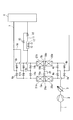
- the purification method of the present invention will be specifically described with reference to FIG.
- the air taken from the atmosphere through the line 1 is compressed to a predetermined pressure (500 to 800 kPa (A)) by the air compressor 2 and then cooled to about 40 ° C. by the aftercooler 3.
- the cooled compressed air separates condensed water with a drain separator (not shown), and enters the pretreatment purification apparatus containing saturated moisture at the cooled temperature.
- the temperature of the compressed air entering the pretreatment purification apparatus is arbitrarily selected in the present invention.
- the pretreatment purification apparatus is composed of two adsorption cylinders 5a and 5b, and these adsorption cylinders are switched to alternately perform adsorption and heating regeneration so that one of the adsorption cylinders is always in the adsorption process. By doing so, the raw material air can be purified continuously. While the adsorption process a is being performed in the adsorption cylinder 5a, the regeneration process by the processes b to e is performed in the adsorption cylinder 5b. The number of adsorption cylinders can be changed as necessary. In the following description, each process is described only for the suction cylinder 5a, and the same process is alternately performed for the suction cylinder 5b, and thus the description thereof is omitted.
- the name of each instrument used for the suction cylinder 5b is also described using the same numerical value with a symbol b, and the description thereof is omitted.
- the adsorption cylinder 5a is filled with a moisture adsorbent 20a such as activated alumina, silica gel, KA type zeolite, or Na-A type zeolite on the raw air introduction side, and Na on the purified air outlet side.
- a moisture adsorbent 20a such as activated alumina, silica gel, KA type zeolite, or Na-A type zeolite on the raw air introduction side, and Na on the purified air outlet side.
- -Filled with carbon dioxide adsorbent 21a such as X-type zeolite.
- the adsorbent layers are separated from each other, and a slight gap is formed.
- a line 26a for introducing heated raw air for partial heating is provided in the gap.
- the raw material air enters the adsorption cylinder 5a by opening the valve 4a, and enters the adsorption cylinder 5b by opening the valve 4b.
- the adsorption cylinder 5a is in the adsorption process, the moisture that has entered the air from the valve 4a is removed by the moisture adsorbent 20a, and then carbon dioxide and other trace impurities are removed by the carbon dioxide adsorbent 21a.
- the purified air is led from a valve 6a through a line 7 to a so-called cold box 8 containing a distillation column for liquefying and distilling the air.
- the water content and carbon dioxide content of the purified air leaving the pretreatment purification apparatus are generally 1 ppm and 0.1 ppm or less, respectively.
- the gas is characterized in that it merges in the middle of the adsorption cylinder.
- modifications such as performing partial heating and total heating in the heating process at different times are possible. It is included in the intended scope of the present invention. Either partial heating or whole heating may be started first or simultaneously, or one of them may be ended first or simultaneously.
- the supply is preferably terminated at the same time.
- a portion of the purified air flowing through the line 7 is returned to the adsorption cylinder 5a through the line 16 and is charged up to the operating pressure of the next adsorption process.
- the valve 17a is closed and the valves 4a and 6a are opened again, so that a new cycle starting from the step a is started.
- the moisture adsorbents 20a and 20b that adsorb water in the raw air and the carbon dioxide adsorbents 21a and 21b that adsorb carbon dioxide are packed in layers.
- a plurality of adsorption cylinders 5a and 5b may be used, and these may be switched and used to continuously purify the raw material air.
- a heating step supplies a heated purge gas that does not contain water and carbon dioxide to the outflow side of the raw material air of the carbon dioxide adsorbent.
- Heating the moisture adsorbent by supplying a carbon dioxide adsorbent and the moisture adsorbent to the entire heating step and supplying heated raw air between the carbon dioxide adsorbent layer and the moisture adsorbent layer.
- the partial heating step is performed in parallel.
- the pre-processing TSA process simulator includes the following assumptions: (1) Gas follows the law of ideal gas, (2) Concentration and temperature distribution in the suction cylinder radial direction does not occur. (3) The gas flow in each adsorbent layer is a plug flow model considering diffusion in the axial direction only. (4) The adsorption speed is a linear driving force (LDF) model. (5) The composition of the raw material air is assumed to be four components of moisture, carbon dioxide, nitrogen and oxygen. The basic equation was derived from these assumptions. For details of the simulation used here, see “Japan Oxygen Technical Bulletin” No. 22, 13-18 (2003).
- Example 1 The method of the present invention was simulated under the same adsorption cylinder conditions as in Comparative Example 1.
- Adsorption cylinder condition cylinder diameter 1.4m Filling height of moisture adsorbent layer 0.808m Filling height of carbon dioxide adsorbent layer 0.655m
- Raw material air conditions 700 kPa (A), 40 ° C., 5800 Nm 3 / h
- Example 1 was calculated in the two-cylinder pretreatment purification apparatus as switching between 2 hours of adsorption process 2 hours and regeneration process 2 hours (decompression, heating, cooling, charging) in each cylinder.
- the purge gas was assumed to be a purified gas containing no water and carbon dioxide, and the same flow rate was introduced in both the heating and cooling steps to regenerate both adsorbents.
- a partial heating step for supplying heated raw air to the moisture adsorbent layer and an overall heating step for supplying a purge gas not containing heated impurities to the carbon dioxide adsorbent layer were performed in parallel.
- the temperature and flow rate of the heated raw air were fixed at 80 ° C. and 580 Nm 3 / h, respectively, and calculation was performed for different conditions of the purge gas flow rate or the purge gas temperature in the heating process. And the condition where water
- Comparative Example 2 A conventional pretreatment purification method was simulated under conditions different from those of Comparative Example 1 below.
- Adsorption cylinder condition cylinder diameter 4.4m Filling height of moisture adsorbent layer 0.945m Filling height of carbon dioxide adsorbent layer 0.657m
- Raw material air conditions 550 kPa (A), 40 ° C., 50000 Nm 3 / h
- the adsorption process is performed for 2 hours and the regeneration process is performed for 2 hours (reduced pressure, heating, cooling, charging) in each cylinder. As above.
- the purge gas was assumed to be a purified gas containing no moisture and carbon dioxide, and the same flow rate was introduced in both the heating and cooling steps to regenerate both adsorbents.
- the calculation was performed for different conditions of the purge gas flow rate or the purge gas temperature in the heating process, and the conditions under which moisture and carbon dioxide breakthrough from the respective adsorbent layers in the adsorption process were examined under each condition.
- Example 2 The method of the present invention was simulated under the same adsorption cylinder conditions as in Comparative Example 2.
- Adsorption cylinder conditions Tower diameter 4.4m Filling height of moisture adsorbent layer 0.945m Filling height of carbon dioxide adsorbent layer 0.657m
- Raw material air conditions 550 kPa (A), 40 ° C., 50000 Nm 3 / h
- switching was performed for 2 hours between an adsorption process of 2 hours and a regeneration process of 2 hours (decompression, heating, cooling, charging) in each cylinder.
- the purge gas is a purified gas containing no water and carbon dioxide
- the same flow rate was introduced in both the heating and cooling steps, and the adsorbent was regenerated.
- the temperature and flow rate of the heated raw air were fixed at 200 ° C. and 5000 Nm 3 / h, respectively, and calculation was performed for different conditions of the purge gas flow rate or the purge gas temperature in the heating process. Under the respective conditions, the situation in which moisture and carbon dioxide broke through from each adsorbent in the adsorption process was investigated.
- waste gas used for purge gas during adsorbent regeneration is reduced and product yield is improved.
Landscapes
- Chemical & Material Sciences (AREA)
- Engineering & Computer Science (AREA)
- Analytical Chemistry (AREA)
- General Chemical & Material Sciences (AREA)
- Oil, Petroleum & Natural Gas (AREA)
- Chemical Kinetics & Catalysis (AREA)
- Physics & Mathematics (AREA)
- Mechanical Engineering (AREA)
- Thermal Sciences (AREA)
- General Engineering & Computer Science (AREA)
- Separation Of Gases By Adsorption (AREA)
- Separation By Low-Temperature Treatments (AREA)
Abstract
Description
本願は、2009年3月11日に、日本に出願された特願2009-058724号に基づき優先権を主張し、その内容をここに援用する。
たとえば、前記不純物を含む空気をそのまま極低温に冷却すると、水、二酸化炭素、及び窒素酸化物が凝固して配管等を閉塞させる可能性や、炭化水素類が液体酸素溜め内で濃縮されて、安全な操業を行う上での阻害要因となる可能性があるためである。
吸着による前処理精製の一つとして、温度スイング吸着法(TSA法)が用いられる。これは、複数の吸着筒を有する前処理精製装置によって行われる。吸着筒には、原料空気の流入口側に水を除去するための吸着剤(たとえば活性アルミナ、シリカゲル、K-A型ゼオライト、Na-A型ゼオライト等)を充填し、その下流側に二酸化炭素を除去するための吸着剤(たとえばNa-X型ゼオライト等)を充填する。
TSA法では、この前処理精製装置を用いて、相対的に低い温度で原料空気中の不純物を吸着する吸着工程と、相対的に高い温度で行われる吸着剤の再生工程と、を交互に行うことで、連続して空気を精製する。
a 加圧空気を吸着筒に導入し前記空気から不純物を除去する吸着工程
b 吸着工程終了後、吸着筒内を大気圧まで減圧する減圧工程
c 減圧工程終了後、不純物を含まないパージガスを加温して吸着筒に導入して、吸着剤を加熱再生する加熱工程
d 加熱工程終了後、不純物を含まないパージガスを加温することなく吸着筒に導入して、吸着筒内を吸着操作可能な温度まで冷却する冷却工程
e 冷却工程終了後、冷却された吸着筒を精製空気により加圧する充圧工程
このような好ましい条件を得るため、従来、原料空気は空気圧縮機により所定の圧力まで圧縮された後、アフタークーラーにより約40℃まで冷却され、さらに冷凍機を用いて5~15℃まで冷却されて、吸着筒に導入されていた。
しかしながら近年、環境にやさしい装置が望まれるようになったことから、フロンを使用した冷凍機(フロン冷凍機)を用いずに前処理精製を行う方法が、日本国特許3416391号により提案された。
前記日本国特許第3416391号公報に記載の発明は、このような悪条件を、以下の(1)~(3)によって解決している。
(1)サイクルタイムの短縮による負荷量の低減
(2)二酸化炭素吸着量の大きい吸着剤の選択
(3)再生時の加熱温度と再生ガス量の最適化
このパージガスは、清浄な空気が望ましい。一般に、深冷空気分離法においては、製品ガス(窒素、酸素、アルゴン等)を得る蒸留工程において生じたガスであるものの、製品とされないガス(廃窒素、もしくは廃ガスと言われる)が、前処理精製装置のパージガスとして用いられてきた。これは、廃ガスを用いることで、水や二酸化炭素等の不純物を除いた空気を別途製造するよりも、コストがかからないためである。
一方製品収率について述べれば、現状の技術レベルでは、窒素のみを製品とする単一カラム方式の深冷空気分離法での蒸留性能から、製品収率が60%程度と言われている。また、酸素および窒素を製品とすることができる複式カラム方式(double column process)の深冷空気分離法では、製品収率は80%程度と言われている。
ただし、深冷空気分離法の製品収率は、深冷空気分離全体のプロセスや操作圧力などの条件に依存するので、ここに示した数値は目安である。
したがって、前処理精製の現状の性能が、深冷空気分離法全体の生産性能の向上を制限しているのが現状である。
近年、深冷空気分離法におけるプロセスの改良などによる蒸留性能の向上で、分離によって得られるガスの製品収率の上昇が見込めるようになった。しかしながら、前処理精製では相変わらずパージガスが多量に必要であり、蒸留工程からの廃ガスの一定量が前処理精製の為に必要なため、向上した蒸留性能に見合った十分な製品収率を得ることができないという問題が生じた。
しかし、近年用いられるようになった高性能の二酸化炭素吸着剤は、水分を吸着することにより二酸化炭素の吸着能力が著しく低下してしまう。この為、特開昭60-139311号公報に記載の発明のように、水と二酸化炭素をある程度含む生空気をパージガスの一部もしくは全部として用いることは、高性能の二酸化炭素吸着剤を使用する場合には採用できない、と考えられていた。
すなわち水分の脱着には多くの熱量が使用される、言い換えれば多くのパージガスが使用されているので、原料空気の精製において、再生ガス率を低減するためには、水分吸着剤の再生方法を工夫する必要があることが判った。
深冷空気分離における原料空気の前処理精製方法であって、
複数の吸着筒を用い、これら吸着筒を、吸着と加熱再生とを交互に行うように切り替えて、いずれかの吸着筒が常に吸着工程にあるようにすることにより連続的に原料空気を精製する方法であり、以下のa~eの工程を含み、
a 加圧した原料空気を、原料空気中の水を吸着する水分吸着剤の層と二酸化炭素を吸着する二酸化炭素吸着剤の層とが、原料空気の流入側からこの順に層状に充填された吸着筒に導入し、前記空気から少なくとも水と二酸化炭素とを除去する吸着工程、
b 吸着工程終了後、吸着筒内を大気圧まで減圧する減圧工程、
c 大気圧まで減圧された吸着筒中の前記水分吸着剤と二酸化炭素吸着剤とを加熱再生する加熱工程、
d 水と二酸化炭素とを含まない、加温されていないパージガスを前記吸着筒に導入し、前記水分吸着剤と二酸化炭素吸着剤とを吸着操作可能な温度まで冷却する冷却工程、
e 冷却された前記水分吸着剤と二酸化炭素吸着剤とを精製された空気により加圧する充圧工程
前記加熱工程cが、
加熱した、水と二酸化炭素とを含まない加熱したパージガスを、前記吸着筒の精製空気流出側供給して前記二酸化炭素吸着剤と前記水分吸着剤を加熱する全体加熱工程と、
加熱した生空気を、前記二酸化炭素吸着剤の層と前記水分吸着剤の層との間に供給して前記水分吸着剤を加熱する部分加熱工程と、
を並行して実施する工程であることを特徴とする、深冷空気分離における原料空気の前処理精製方法である。
さらに、工程cの前記部分加熱工程を行うための生空気の供給温度は60~250℃であることが好ましい。
また、工程cの前記全体加熱工程を行うためのパージガスの供給温度は100~250℃であることが好ましい。
工程cの前記部分加熱工程を行うための生空気の供給量が、前処理精製装置で処理する空気量の5~15%であることが好ましい。
本発明の原料空気の精製方法は、深冷空気分離方法の原料空気の前処理精製に使用できる。
本発明は、加熱再生する工程において、加熱した生空気を水分吸着剤層に供給する部分加熱工程と、不純物を含まない加熱した廃ガスをパージガスとして二酸化炭素吸着剤層に供給することによる全体加熱工程と、を組み合わせて実施することを特徴とする。
ここで、部分加熱工程における加熱した生空気の供給は、水分吸着剤の充填部分のみに対して行う。
また部分加熱工程で水分吸着剤を再生している間に、不純物を含まない加熱した廃ガスをパージガスとして、二酸化炭素吸着剤充填部分に供給する。この事により、二酸化炭素吸着剤を再生する全体加熱工程を部分加熱工程と同時に実施できる。これら工程で、二酸化炭素吸着剤は加熱されたパージガスでのみ加熱されるが、水分吸着剤は加熱された生空気、パージガス、あるいは生空気とパージガスの混合ガスによって加熱される。
本発明において、部分加熱工程に使う生空気は任意に選択でき、原料空気圧縮機の低圧部分から一部を導き出したものでも良い。別途、部分加熱用の空気ブロワー等を用意することも差し支えない。
また、全体加熱工程を行うための不純物を含まないパージガスは、二酸化炭素吸着剤層の精製ガス出口端から供給する。
部分加熱工程用の生空気の圧力は、水分吸着剤層を通って流れるに十分な圧力であれば良い。
吸着剤を加熱再生する工程において、水分吸着剤充填部分の部分加熱工程を行うための生空気の供給量は、前処理精製において処理する原料空気量の5~15%であることが望ましい。この量より少ないと、生空気加熱の効果が現れない。この量より多いと、原料空気圧縮機の吐出量に影響を与える。
大気からライン1を通って取り込まれた空気は、空気圧縮機2により所定の圧力(500~800kPa(A))に圧縮された後、アフタークーラー3により約40℃まで冷却される。冷却された圧縮空気はドレインセパレーター(図示せず)で凝縮水を分離し、冷却された温度における飽和水分を含んで前処理精製装置に入る。前処理精製装置に入る圧縮空気の温度は本発明において任意に選択される。
なお、以下の説明では、吸着筒5aについてのみ各工程を説明し、吸着筒5bについては、同様の工程が交互に行われるので、その説明を省略する。吸着筒5bに使用される各器具の名称についても同じ数値にbがついた記号を用いて記載し、その説明を省略する。
吸着筒5aには、その原料空気導入側には、活性アルミナ、シリカゲル、K-A型ゼオライト、またはNa-A型ゼオライトなどの水分吸着剤20aが充填され、その精製空気導出側には、Na-X型ゼオライトなどの二酸化炭素吸着剤21aが充填されている。両吸着剤層の間は分離されており、わずかな空隙が形成されている。この空隙には部分加熱のための加熱生空気を導入するためのライン26aが設けられている。
吸着工程では、弁4aを開けることで原料空気は吸着筒5aに入り、また弁4bを開けることで吸着筒5bに入る。吸着筒5aが吸着工程にあるとき、弁4aから入った空気は水分吸着剤20aにより水分が除去され、次いで二酸化炭素吸着剤21aにより二酸化炭素およびその他の微量不純物が除去される。
精製された空気は、弁6aからライン7を介して、空気を液化蒸留する蒸留塔を収納した、いわゆるコールドボックス8へ導かれる。前処理精製装置を出た精製空気の水分、二酸化炭素含有量は、一般的にそれぞれ1ppm、0.1ppm以下である。
吸着筒5aの吸着工程が終了したら、弁4a、6aが閉じられ、弁9aを開ける。弁9aを開けることで、吸着筒5aに保持されたガスはサイレンサー(図示せず)を介して大気に放出され、筒内の圧力は大気圧近くまで減圧される。
*部分加熱
筒内が大気圧近くまで減圧された後、弁18aが開き加熱された生空気がライン25からライン26aを経て吸着筒5aに供給される。弁9aが開けられており、生空気は吸着筒5aの水分吸着剤20a側に向かって供給されるので、水分吸着剤20aの加熱が行われ、廃ガスは吸着筒を出て弁9aを介して大気へ放出される。なお二酸化炭素吸着剤と水分吸着剤との間に設けられたライン26aの末端は水分吸着剤に接近して、又は接触して、あるいは水分吸着剤の中に設けられてもよい。
*全体加熱
弁13、弁14aを開けることで、コールドボックス8からの廃ガスは、ライン11を介して加熱設備12に入り、所定温度まで加熱されて、弁14aを通り、パージガスとして吸着筒5aに導入される。
加熱された廃ガスをパージガスとして用いる事により、二酸化炭素吸着剤21a、水分吸着剤20aの順で加熱を行い、吸着剤の再生が行われ、再生に使用された廃ガスは開いている弁9aを介して大気へ放出される。
なお本発明では、加熱工程において、吸着筒の途中での合流が行われる限り、加熱工程における部分加熱と全体加熱とを、時間をずらして行う等の改変は可能であり、そのような改変は本発明の意図する範囲に含まれる。部分加熱と全体加熱のどちらかが先に、あるいは同時にスタートしても良いし、どちらかが先に供給を終了しても、あるいは同時に終了しても良い。
供給は同時に終了することが好ましい。
水分吸着剤20aの最下部(原料空気流入口)の吸着剤が所定の温度(90~130℃)まで上がったら(所定の時間で温度が上がるように、パージガス量、加熱設備容量が決められる)、冷却工程の為に、弁13が閉じられ、弁15が開けられる。
前記操作によってパージガスは加熱されることなく、弁14aを通って吸着筒5aに供給される為、吸着剤は次第に冷却される。排ガスは弁9aから大気へ放出される。
(充圧工程)
冷却工程が終わると、弁9a、14a、15が閉じられ、弁17aが開けられる。ライン7を流れている精製された空気の一部がライン16を介して吸着筒5aに戻されて、次の吸着工程の操作圧力まで充圧される。充圧が終了すると弁17aを閉じて、弁4a、6aを再び開けることで、工程aから始まる新たなサイクルが開始される。
このように図1に示される精製装置を用いる精製方法は、原料空気中の水を吸着する水分吸着剤20a、20bと二酸化炭素を吸着する二酸化炭素吸着剤21a、21bとが層状に充填された、複数であってよい吸着筒5a、5bを用い、これを切り替え使用して連続的に原料空気を精製する方法である。吸着工程、減圧工程、加熱工程、冷却工程、充圧工程を含み、加熱工程が、水と二酸化炭素とを含まない加熱したパージガスを前記二酸化炭素吸着剤の原料空気の流出側に供給して前記二酸化炭素吸着剤と前記水分吸着剤を加熱する全体加熱工程と、加熱した生空気を前記二酸化炭素吸着剤の層と前記水分吸着剤の層との間に供給することにより前記水分吸着剤を加熱する部分加熱工程とを並行して実施する。
前処理TSAプロセスのシミュレーターは、以下の仮定を含む。
(1)ガスは理想気体の法則に従う、
(2)吸着筒半径方向の濃度および温度分布は生じない、
(3)各吸着剤層内のガス流れは軸方向のみの拡散を考慮したプラグフローモデルとする、
(4) 吸着速度は線形推進力(LDF)モデルとする、
(5) 原料空気の組成は水分、二酸化炭素、窒素、酸素の4成分とする
これらの仮定から基礎方程式を導出した。ここで使用したシミュレーションの詳細は、「日本酸素技報」No.22、13-18(2003)に開示されている。
以下の条件で、従来の前処理精製方法をシミュレーションした。
吸着筒条件:筒径1.4m
水分吸着剤層の充填高さ0.808m
二酸化炭素吸着剤層の充填高さ0.655m
原料空気条件:700kPa(A)、40℃、5800Nm3/h
従来の前処理精製方法として、2筒式前処理精製装置において、各筒における吸着工程2時間、再生工程2時間(減圧、加熱、冷却、充圧)の2時間切替えとして計算した。なお、パージガスは水分と二酸化炭素を含まない精製ガスと仮定した。
加熱工程および冷却工程とも、同じ流量を導入し、両吸着剤の再生を行う。パージガスの流量およびパージガス温度の異なる条件について計算を行い、それぞれの条件において、吸着工程で水分および二酸化炭素がそれぞれ水分吸着剤および二酸化炭素吸着剤から破過する状況を調べた。
パージガスの流量を徐々に減らしながらパージガスの温度を変える計算を繰り返し、水分吸着剤層から水分が、および二酸化炭素吸着剤層から二酸化炭素が破過する状況を調べた。
この結果、水分吸着剤層から水分が、および二酸化炭素吸着剤層から二酸化炭素が破過しない条件は、パージガス流量の下限として2610Nm3/h(再生ガス率=パージガス流量/原料空気流量=45%)であり、このときの再生ガス温度は210℃であった。
本検討における前処理精製装置の条件では、さらにパージガス流量を減らすと、パージガスの温度を上げても、パージガス流れ方向の下流側にある水分吸着剤に再生に必要な熱が十分伝わらず再生ができなかった。
なお、この計算において、水分吸着剤層の最下部(空気流入口)の吸着剤が90~130℃まで上がることが、吸着剤の再生完了、ひいては水、二酸化炭素の破過が起こらないことの目安になることが判った。
比較例1と同じ吸着筒の条件で、本発明の方法をシミュレーションした。
吸着筒条件:筒径 1.4m
水分吸着剤層の充填高さ 0.808m
二酸化炭素吸着剤層の充填高さ 0.655m
原料空気条件:700kPa(A)、40℃、5800Nm3/h
実施例1は、2筒式前処理精製装置において、各筒における吸着工程2時間、再生工程2時間(減圧、加熱、冷却、充圧)の2時間切替えするものとして計算した。
パージガスは水分と二酸化炭素を含まない精製ガスと仮定し、加熱工程および冷却工程とも、同じ流量を導入し、両吸着剤の再生を行った。
加熱工程では、加熱した生空気を水分吸着剤層に供給する部分加熱工程と、加熱した不純物を含まないパージガスを二酸化炭素吸着剤層に供給することによる全体加熱工程とを並行的に実施した。
本実施例では、加熱した生空気の温度と流量は、それぞれ80℃、580Nm3/hで一定とした上で、パージガスの流量もしくは加熱工程でのパージガス温度の異なる条件について計算を行った。そして、各条件において吸着工程で水分および二酸化炭素がそれぞれの吸着剤層から破過する状況を調べた。
パージガスの流量を徐々に減らしながらパージガスの温度を変える計算を繰り返し、水分吸着剤層から水分が、および二酸化炭素吸着剤層から二酸化炭素が破過する状況を調べた。
この結果、水分吸着剤層から水分が、および二酸化炭素吸着剤層から二酸化炭素が破過しない条件は、比較例1と同じパージガス温度210℃で、パージガス流量の下限として2030Nm3/h(再生ガス率=パージガス流量/原料空気流量=35%)であった。
本発明により、従来プロセスとの比較において、パージガスの流量を580Nm3/h削減できる。その分、深冷分離装置からの廃ガスを減少させられるので、製品ガス増量が可能となる事が分かる。
吸着筒条件:筒径4.4m
水分吸着剤層の充填高さ 0.945m
二酸化炭素吸着剤層の充填高さ 0.657m
原料空気条件:550kPa(A)、40℃、50000Nm3/h
比較例1とは別の従来の前処理精製方法として、2筒式前処理精製装置において、各筒における吸着工程2時間、再生工程2時間(減圧、加熱、冷却、充圧)の2時間切替えとして、上記の条件で計算した。パージガスは水分と二酸化炭素を含まない精製ガスと仮定し、加熱工程および冷却工程とも、同じ流量を導入し、両吸着剤を再生するとした。
また、パージガスの流量もしくは加熱工程でのパージガス温度の異なる条件について計算を行い、それぞれの条件において吸着工程で水分および二酸化炭素がそれぞれの吸着剤層から破過する状況を調べた。
パージガスの流量を減らし、各流量においてパージガスの温度を変えて、水分吸着剤層から水分が、および二酸化炭素吸着剤層から二酸化炭素が破過する状況を調べた。
この結果、水分吸着剤層から水分が、および二酸化炭素吸着剤層から二酸化炭素が破過しない条件は、パージガス流量の下限として27000Nm3/h(再生ガス率=パージガス流量/原料空気流量=54%)、このときのパージガス温度は210℃であった。
本前処理精製装置の条件では、さらにパージガス流量を減らすと、パージガスの温度を上げても、パージガス流れ方向の下流側にある水分吸着剤に、再生に必要な熱が十分伝わらず再生ができなかった。
比較例2と同じ吸着筒の条件で、本発明の方法をシミュレーションした。
吸着筒条件:塔径4.4m
水分吸着剤層の充填高さ 0.945m
二酸化炭素吸着剤層の充填高さ 0.657m
原料空気条件:550kPa(A)、40℃、50000Nm3/h
2筒式前処理精製装置において、各筒における吸着工程2時間、再生工程2時間(減圧、加熱、冷却、充圧)の2時間切替とした。パージガスは水分と二酸化炭素を含まない精製ガスと仮定し、加熱工程および冷却工程とも、同じ流量を導入し、吸着剤の再生を行なうものとして計算した。
なお加熱工程では、加熱した生空気を水分吸着剤層の充填部分に供給する部分加熱工程と、加熱した不純物を含まないパージガスを二酸化炭素吸着剤層の充填部分に供給することによる全体加熱工程とを、並行的に実施した。
本実施例では、加熱した生空気の温度と流量はそれぞれ200℃、5000Nm3/hで一定とした上で、パージガスの流量もしくは加熱工程でのパージガス温度の異なる条件について計算を行った。それぞれの条件において吸着工程で水分および二酸化炭素がそれぞれの吸着剤から破過する状況を調べた。
パージガスの流量を減らし、各流量でパージガスの温度を上げて、水分吸着剤層から水分が、および二酸化炭素吸着剤層から二酸化炭素が破過する状況を調べた。
この結果、水分吸着剤層から水分が、および二酸化炭素吸着剤層から二酸化炭素が破過しない条件は、比較例1と同じ再生ガス温度210℃で、パージガス流量の下限として22500Nm3/h(再生ガス率=パージガス流量/原料空気流量=45%)であった。
従来プロセスとの比較において、本発明によりパージガスの流量を4500Nm3/h削減でき、その分の製品ガス増量が可能となる。
2 空気圧縮機
3 アフタークーラー
4a、4b 弁
5a、5b 吸着筒
7 ライン
8 コールドボックス8
20a、20b 水分吸着剤
21a、21b 二酸化炭素吸着剤
12 加熱設備
25 ライン
26a、26b ライン
Claims (5)
- 深冷空気分離における原料空気の前処理精製方法であって、
複数の吸着筒を用い、これら吸着筒を、吸着と加熱再生とを交互に行うように切り替えて、いずれかの筒が常に吸着工程にあるようにすることにより連続的に原料空気を精製する方法であり、以下のa~eの工程を含み、
a 加圧した原料空気を、原料空気中の水を吸着する水分吸着剤と二酸化炭素を吸着する二酸化炭素吸着剤とが、原料空気の流入側からこの順に層状に充填された吸着筒に導入し、前記空気から少なくとも水と二酸化炭素とを除去する吸着工程、
b 吸着工程終了後、吸着筒内を大気圧まで減圧する減圧工程、
c 大気圧まで減圧された吸着筒中の前記水分吸着剤と二酸化炭素吸着剤とを加熱再生する加熱工程、
d 水と二酸化炭素とを含まない、加温されていないパージガスを前記吸着筒に導入し、前記水分吸着剤と二酸化炭素吸着剤とを吸着操作可能な温度まで冷却する冷却工程、
e 冷却された前記水分吸着剤と二酸化炭素吸着剤とを、精製された空気により加圧する充圧工程、
前記加熱工程cが、
水と二酸化炭素とを含まない、加熱したパージガスを、前記吸着筒の精製空気の流出側に供給して前記二酸化炭素吸着剤と前記水分吸着剤を加熱する全体加熱工程と、
加熱した生空気を、前記二酸化炭素吸着剤の層と前記水分吸着剤の層との間に供給して前記水分吸着剤を加熱する部分加熱工程と、
を並行して実施する工程であることを特徴とする、深冷空気分離における原料空気の前処理精製方法。 - 工程cの前記部分加熱工程を行うための生空気の供給温度が60~250℃であることを特徴とする請求項1記載の深冷空気分離における原料空気の前処理精製方法。
- 工程cの前記全体加熱工程を行うためのパージガスの供給温度が100~250℃であることを特徴とする請求項1記載の深冷空気分離における原料空気の前処理精製方法。
- 工程cの前記部分加熱工程を行うための生空気の供給量が、前処理精製で処理する空気量の5~15%であることを特徴とする請求項1記載の深冷空気分離における原料空気の前処理精製方法。
- 請求項1記載の原料空気の前処理精製方法を含む、深冷空気分離方法。
Priority Applications (2)
| Application Number | Priority Date | Filing Date | Title |
|---|---|---|---|
| CN2010800112666A CN102348489A (zh) | 2009-03-11 | 2010-02-25 | 空气的提纯方法 |
| US13/255,634 US8690990B2 (en) | 2009-03-11 | 2010-02-25 | Method of purifying air |
Applications Claiming Priority (2)
| Application Number | Priority Date | Filing Date | Title |
|---|---|---|---|
| JP2009058724A JP5577044B2 (ja) | 2009-03-11 | 2009-03-11 | 空気の精製方法 |
| JP2009-058724 | 2009-03-11 |
Publications (1)
| Publication Number | Publication Date |
|---|---|
| WO2010103739A1 true WO2010103739A1 (ja) | 2010-09-16 |
Family
ID=42728038
Family Applications (1)
| Application Number | Title | Priority Date | Filing Date |
|---|---|---|---|
| PCT/JP2010/001274 Ceased WO2010103739A1 (ja) | 2009-03-11 | 2010-02-25 | 空気の精製方法 |
Country Status (4)
| Country | Link |
|---|---|
| US (1) | US8690990B2 (ja) |
| JP (1) | JP5577044B2 (ja) |
| CN (1) | CN102348489A (ja) |
| WO (1) | WO2010103739A1 (ja) |
Families Citing this family (19)
| Publication number | Priority date | Publication date | Assignee | Title |
|---|---|---|---|---|
| WO2013171628A1 (en) * | 2012-05-16 | 2013-11-21 | Koninklijke Philips N.V. | Oxygen separator and method of generating oxygen |
| CN102657995B (zh) * | 2012-05-18 | 2014-09-17 | 神华集团有限责任公司 | 深冷空分装置的吸附系统 |
| US9861929B2 (en) * | 2015-05-15 | 2018-01-09 | Exxonmobil Upstream Research Company | Apparatus and system for swing adsorption processes related thereto |
| CN104841244B (zh) * | 2015-05-19 | 2016-09-21 | 南京都乐制冷设备有限公司 | 制鞋行业用常压解析的吸附式丙酮回收系统及回收方法 |
| US10105637B2 (en) | 2015-09-25 | 2018-10-23 | Praxair Technology, Inc. | Adsorbent regeneration method |
| US9802149B1 (en) * | 2015-12-16 | 2017-10-31 | The United States Of America As Represented By The Administrator Of Nasa | Sorbent-based atmosphere revitalization system |
| US9795915B2 (en) * | 2016-01-29 | 2017-10-24 | Air Products And Chemicals, Inc. | Heater arrangement for TEPSA system |
| US10895417B2 (en) * | 2016-03-25 | 2021-01-19 | L'air Liquide Societe Anonyme Pour L'etude Et L'exploitation Des Procedes Georges Claude | Method for the production of air gases by the cryogenic separation of air with improved front end purification and air compression |
| US10663222B2 (en) * | 2018-04-25 | 2020-05-26 | Praxair Technology, Inc. | System and method for enhanced recovery of argon and oxygen from a nitrogen producing cryogenic air separation unit |
| CN110013736B (zh) * | 2018-07-09 | 2020-01-10 | 上海深城环保设备工程有限公司 | 一种气体吸附分离装置 |
| US11137205B2 (en) * | 2018-12-21 | 2021-10-05 | L'air Liquide Societe Anonyme Pour L'etude Et L'exploitation Des Procedes Georges Claude | Method and apparatus for eliminating heat bumps following regeneration of adsorbers in an air separation unit |
| KR20230008178A (ko) | 2020-05-11 | 2023-01-13 | 프랙스에어 테크놀로지, 인코포레이티드 | 중압 극저온 공기 분리 유닛에서 질소, 아르곤, 및 산소의 회수를 위한 시스템 및 방법 |
| KR102932115B1 (ko) | 2020-05-15 | 2026-03-03 | 프랙스에어 테크놀로지, 인코포레이티드 | 질소 및 아르곤 생성 극저온 공기 분리 유닛용 통합형 질소 액화기 |
| TWI809444B (zh) * | 2020-08-19 | 2023-07-21 | 美商普雷瑟科技股份有限公司 | 用於預純化進料氣流之方法 |
| US11619442B2 (en) | 2021-04-19 | 2023-04-04 | Praxair Technology, Inc. | Method for regenerating a pre-purification vessel |
| JP2023050236A (ja) * | 2021-09-30 | 2023-04-11 | 大陽日酸株式会社 | 酸素製造方法 |
| JP7678236B2 (ja) * | 2022-10-31 | 2025-05-15 | 大陽日酸株式会社 | 空気精製装置及び空気精製方法 |
| KR20260018064A (ko) * | 2023-05-22 | 2026-02-06 | 더 유니버시티 오브 멜버른 | 이산화탄소 포집 방법 및 시스템 |
| US12595960B2 (en) * | 2023-06-26 | 2026-04-07 | Air Products And Chemicals, Inc. | Adsorber, purification system, and purification method |
Citations (3)
| Publication number | Priority date | Publication date | Assignee | Title |
|---|---|---|---|---|
| JPS6125640A (ja) * | 1984-07-13 | 1986-02-04 | Kurita Water Ind Ltd | 吸着剤の再生方法 |
| JPH1015331A (ja) * | 1996-07-01 | 1998-01-20 | Kawai Gijutsu Kenkyusho:Kk | 加熱再生式圧力スイング吸着方法 |
| JPH1057744A (ja) * | 1996-07-03 | 1998-03-03 | Praxair Technol Inc | 多熱パルス式psa系 |
Family Cites Families (12)
| Publication number | Priority date | Publication date | Assignee | Title |
|---|---|---|---|---|
| FR2127112A5 (ja) * | 1971-02-24 | 1972-10-13 | Air Liquide | |
| US4233038A (en) * | 1979-08-06 | 1980-11-11 | Air Products And Chemicals, Inc. | Reactivation system for water-carbon dioxide adsorbers |
| US4472178A (en) * | 1983-07-05 | 1984-09-18 | Air Products And Chemicals, Inc. | Adsorptive process for the removal of carbon dioxide from a gas |
| JPS60139311A (ja) | 1983-12-28 | 1985-07-24 | Hitachi Ltd | 吸着塔の再生方法 |
| GB9424191D0 (en) * | 1994-11-30 | 1995-01-18 | Boc Group Plc | Purification apparatus |
| JP3416391B2 (ja) | 1995-05-25 | 2003-06-16 | 日本酸素株式会社 | 空気液化分離装置の前処理方法及び装置 |
| US5914455A (en) * | 1997-09-30 | 1999-06-22 | The Boc Group, Inc. | Air purification process |
| FR2775198B1 (fr) * | 1998-02-26 | 2000-04-14 | Air Liquide | Procede et dispositif de purification de gaz par adsorption a lits horizontaux fixes |
| US6106593A (en) * | 1998-10-08 | 2000-08-22 | Air Products And Chemicals, Inc. | Purification of air |
| TW500625B (en) * | 1999-06-04 | 2002-09-01 | Nippon Oxygen Co Ltd | Gas treatment agent, its production thereof, gas refining method, gas refiner and gas refining apparatus |
| JP4755328B2 (ja) * | 1999-07-29 | 2011-08-24 | リンデ アクチエンゲゼルシヤフト | 空気浄化方法及び装置 |
| GB0216914D0 (en) * | 2002-07-19 | 2002-08-28 | Air Prod & Chem | Process and apparatus for treating a feed gas |
-
2009
- 2009-03-11 JP JP2009058724A patent/JP5577044B2/ja active Active
-
2010
- 2010-02-25 US US13/255,634 patent/US8690990B2/en active Active
- 2010-02-25 CN CN2010800112666A patent/CN102348489A/zh active Pending
- 2010-02-25 WO PCT/JP2010/001274 patent/WO2010103739A1/ja not_active Ceased
Patent Citations (3)
| Publication number | Priority date | Publication date | Assignee | Title |
|---|---|---|---|---|
| JPS6125640A (ja) * | 1984-07-13 | 1986-02-04 | Kurita Water Ind Ltd | 吸着剤の再生方法 |
| JPH1015331A (ja) * | 1996-07-01 | 1998-01-20 | Kawai Gijutsu Kenkyusho:Kk | 加熱再生式圧力スイング吸着方法 |
| JPH1057744A (ja) * | 1996-07-03 | 1998-03-03 | Praxair Technol Inc | 多熱パルス式psa系 |
Also Published As
| Publication number | Publication date |
|---|---|
| US8690990B2 (en) | 2014-04-08 |
| CN102348489A (zh) | 2012-02-08 |
| JP2010210190A (ja) | 2010-09-24 |
| JP5577044B2 (ja) | 2014-08-20 |
| US20120011887A1 (en) | 2012-01-19 |
Similar Documents
| Publication | Publication Date | Title |
|---|---|---|
| JP5577044B2 (ja) | 空気の精製方法 | |
| CN105431697B (zh) | 空气压缩系统及方法 | |
| JP4252668B2 (ja) | ガス精製方法 | |
| TWI480089B (zh) | 空氣純化方法 | |
| CA2999758C (en) | Adsorbent regeneration method in a combined pressure and temperature swing adsorption process | |
| CN1332737C (zh) | 用于空气液化分离的纯化装置与方法 | |
| US8268045B2 (en) | Compressed air producing method and producing plant | |
| JPH0127962B2 (ja) | ||
| RU2012142676A (ru) | Способ адсорбционной сушки очищенного биогаза и регенерация загруженных адсорбентов | |
| JPS63107720A (ja) | 空気中の水分および炭酸ガスの分離除去方法 | |
| CN108557787A (zh) | 一种回收粗氩气再提纯方法 | |
| JP2004148315A (ja) | 原料ガス流からの亜酸化窒素除去方法及び装置 | |
| JP6163238B2 (ja) | 吸着分離によって空気から酸素を分離して取得する方法およびそのための装置 | |
| CN114483546A (zh) | 一种提高空压站的压缩空气品质的方法 | |
| JP4719598B2 (ja) | 空気液化分離における前処理方法及び装置 | |
| JP2022105394A (ja) | 吸着塔 | |
| JP4621252B2 (ja) | 空気液化分離における原料空気の精製方法および精製装置 | |
| JP7319830B2 (ja) | 窒素製造方法及び装置 | |
| JP7502962B2 (ja) | ガス精製装置及びガス精製方法 | |
| JP2000279740A (ja) | 水及び二酸化炭素の含有量を低減した空気を製造する方法、及び、そのための装置、並びに、吸着剤の再生方法 | |
| JP2025015189A (ja) | 空気分離装置の前処理方法およびその前処理装置、ならびに炭酸ガス回収方法 | |
| JP2026040933A (ja) | 空気精製方法および空気精製装置 | |
| JPH10211412A (ja) | 混合ガス分離方法 |
Legal Events
| Date | Code | Title | Description |
|---|---|---|---|
| WWE | Wipo information: entry into national phase |
Ref document number: 201080011266.6 Country of ref document: CN |
|
| 121 | Ep: the epo has been informed by wipo that ep was designated in this application |
Ref document number: 10750498 Country of ref document: EP Kind code of ref document: A1 |
|
| WWE | Wipo information: entry into national phase |
Ref document number: 13255634 Country of ref document: US |
|
| NENP | Non-entry into the national phase |
Ref country code: DE |
|
| 122 | Ep: pct application non-entry in european phase |
Ref document number: 10750498 Country of ref document: EP Kind code of ref document: A1 |