WO2010103715A1 - カバー装着体の製造装置及び製造方法 - Google Patents
カバー装着体の製造装置及び製造方法 Download PDFInfo
- Publication number
- WO2010103715A1 WO2010103715A1 PCT/JP2010/000411 JP2010000411W WO2010103715A1 WO 2010103715 A1 WO2010103715 A1 WO 2010103715A1 JP 2010000411 W JP2010000411 W JP 2010000411W WO 2010103715 A1 WO2010103715 A1 WO 2010103715A1
- Authority
- WO
- WIPO (PCT)
- Prior art keywords
- outer tube
- cover
- pushing
- cover member
- outer diameter
- Prior art date
- Legal status (The legal status is an assumption and is not a legal conclusion. Google has not performed a legal analysis and makes no representation as to the accuracy of the status listed.)
- Ceased
Links
Images



Classifications
-
- D—TEXTILES; PAPER
- D07—ROPES; CABLES OTHER THAN ELECTRIC
- D07B—ROPES OR CABLES IN GENERAL
- D07B7/00—Details of, or auxiliary devices incorporated in, rope- or cable-making machines; Auxiliary apparatus associated with such machines
- D07B7/02—Machine details; Auxiliary devices
- D07B7/14—Machine details; Auxiliary devices for coating or wrapping ropes, cables, or component strands thereof
Definitions
- the present invention relates to a cover mounting body manufacturing apparatus and manufacturing method, and more specifically, a cover mounting body manufacturing apparatus and a simple manufacturing method capable of manufacturing a cover mounting body having equivalent quality simply and with high yield. Nevertheless, the present invention relates to a method for manufacturing a cover mounting body that can manufacture a cover mounting body having the same quality with a high yield.
- long objects such as strings, rod-shaped bodies, chains, etc.
- cover members such as strings, rod-shaped bodies, chains, etc.
- cover members such as connectors, locking pieces, protective members, and the like are often attached to the end portions and the like.
- a cover member having elasticity hereinafter sometimes simply referred to as a cover member
- Patent Document 1 describes a cover fixing method and a device for fixing a cover member to a member to be covered as a method for attaching a cover member to the long object.
- the cover insertion member is separated from the elastic cover member and the covered body while the cover is left on the covered body, and the remaining elastic cover member is integrally fixed to the covered body by an elastic force.
- a cover fixing device for fixing an elastic cover member to a body to be covered, wherein a small diameter portion, a taper portion, and a large diameter portion are formed coaxially, and the large diameter portion
- a cover insertion member having a hole for inserting the covered body, and pressing the elastic cover member while being inflated by elastic deformation, passing the small diameter portion, the taper portion and the large diameter portion, and the large diameter Cover pushing means for pushing into the covered body inserted into the hole of the part, and after the elastic cover member is pushed into the covered body, the cover inserting member is released and the elastic cover member is moved by elastic force.
- the “cover fixing method and apparatus” described in Patent Document 1 describes that “a small diameter portion, a tapered portion, and a large diameter portion are formed coaxially, and a hole for inserting a cover body into the large diameter portion is provided.
- Patent Document 1 in order to manufacture a covered body to which an elastic cover member is fixed by the cover fixing method and the cover fixing device, when the elastic cover member 4 is pushed into the large diameter portion 3a, for example, The pushing member 5 shown in FIG. 4 and the like, the pliers 6 shown in FIG. 9 (see the 0024 column and FIG. 9 etc.), the claims 10 (FIGS. 28 to 31) and the claims 11 (see FIG. 32).
- the devices 13, 30 are used.
- An object of the present invention is to provide an apparatus for manufacturing a cover mounting body capable of manufacturing a cover mounting body having equivalent quality easily and with a high yield.
- an object of the present invention is to provide a method for manufacturing a cover mounting body that can manufacture a cover mounting body having the same quality with a high yield, although it is a simple manufacturing method.
- Claim 1 is a cover mounting body manufacturing apparatus for manufacturing a cover mounting body formed by mounting a cover member on a long covered member, ⁇ A middle shaft body having an outer diameter changing portion that gradually decreases in outer diameter toward the tip, and both ends are opened, and the middle shaft body is inserted so that the outer diameter changing portion protrudes from the tip portion.
- An insertion jig having an outer tube, -Each of the first pushing arm and the second pushing arm is formed with a pushing portion having an abutting portion formed around a penetrating recess that forms a penetrating portion through which the central shaft passes, And the said penetration recessed part which opposes mutually is arrange
- the said cover member inserted and arrange
- the abutting portion abuts on an end portion, and the cover member is pushed relatively toward the outer tube side along the axial direction of the middle shaft body and is expanded in diameter by the outer diameter changing portion.
- a pushing member exterior to A regulating member that has a regulating surface formed around a through-hole that allows the outer tube to pass therethrough, and that restricts the cover member that is sheathed from the outer tube protruding from the through-hole from moving backward together with the outer tube.
- the pushing member includes an opening amount adjusting means for adjusting the opening amount of the penetrating portion according to the relative position of the pushing member along the axial direction.
- the apparatus for manufacturing a cover mounting body according to Item 1 includes: A guide member having a guide outer diameter changing portion whose outer diameter gradually decreases toward the tip at an inclination ratio corresponding to the inclination ratio of the outer diameter changing portion; A first adjusting arm that has a guided portion at the tip that is positioned on the axis of the guide member and that contacts the guide outer diameter changing portion, and that is coupled to each of the first push arm and the second push arm; A second adjustment arm; A telescopic member that connects the first push arm and the second push arm close to or remotely from each other; The guided portion slides in the axial direction on the outer peripheral surface of the guide outer diameter changing portion, whereby the first pushing arm and the second pushing arm are moved through the first adjusting arm and the second adjusting
- a fourth aspect of the present invention is the apparatus for manufacturing a cover mounting body according to the first aspect, comprising a plurality of the insertion jig, the pushing member, and the regulating member.
- Claim 5 is a manufacturing method of a cover mounting body formed by mounting a cover member on a long covered member, ⁇ Outer diameter change in which the outer tube projects from the through hole of the regulating member having a regulating surface formed around the through hole that penetrates the outer tube having both ends opened, and the outer diameter gradually decreases toward the tip.
- the cover member is relatively pushed toward the outer tube along the axial direction of the middle shaft body, and the outer tube is covered with the outer tube while being expanded in diameter by the outer diameter changing portion; and
- the method for manufacturing a cover mounting body includes the step of inserting and arranging a cover member on the middle shaft body protruding from the outer tube, the step of covering and arranging the cover member on the outer tube, and the step of retracting the middle shaft body. And the step of inserting and arranging the covered member in the outer tube, and the step of retracting the outer tube, and the step of inserting and arranging the covered member in the outer tube Since the cover member is attached to the covered member without passing through the outer tube, the outer tube is formed even though each step is simple. It is possible to easily and stably hold the relative positional relationship between the cover member and the member to be covered disposed through the cover until the manufacture of the cover mounting body is completed.
- the manufacturing apparatus of the cover mounting body which concerns on this invention is provided with the said insertion jig, the said pushing member, the said insertion jig moving means, and the said control means, manufacture of the cover mounting body which concerns on this invention Since the cover member is preferably used for carrying out the method and the cover member does not pass through the outer tube, the manufacture of the cover mounting body completes the relative positional relationship between the cover member and the covered member arranged via the outer tube. Can be easily and stably held.
- cover mounting bodies manufactured by the method for manufacturing a cover mounting body according to the present invention and the apparatus for manufacturing a cover mounting body according to the present invention are such that the cover member is mounted uniformly on the covered member. Have the quality.
- a cover mounting body manufacturing apparatus and a simple manufacturing method capable of manufacturing a cover mounting body having an equivalent quality simply and with a high yield can be obtained. It is possible to provide a method for manufacturing a cover mounting body capable of manufacturing the cover mounting body having a good yield.
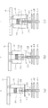
- FIG. 1 is a schematic front view showing a cover mounting body manufacturing apparatus according to an embodiment of the cover mounting body manufacturing apparatus according to the present invention.
- FIG. 2 is a schematic left side view showing a cover mounting body manufacturing apparatus according to an embodiment of the cover mounting body manufacturing apparatus according to the present invention.
- FIG. 3 is a schematic view showing a lower portion of the pushing member in the cover mounting body manufacturing apparatus according to an embodiment of the cover mounting body manufacturing apparatus according to the present invention.
- FIG. 4 is a schematic front view showing an insertion jig in the cover mounting body manufacturing apparatus of one embodiment of the cover mounting body manufacturing apparatus according to the present invention, and FIG. 4 (a) is a cover mounting body according to the present invention.
- FIG.4 (b) is the cover mounting of one Example in the manufacturing apparatus of the cover mounting body which concerns on this invention.
- FIG.4 (c) is another of the center shaft body in the manufacturing apparatus of the cover mounting body of one Example in the manufacturing apparatus of the cover mounting body which concerns on this invention.
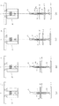
- FIG. 5 is an explanatory view for explaining an example of a method for manufacturing a cover mounting body according to the present invention.
- FIG. 5 (a) is a schematic explanatory view for explaining an initial state of the cover mounting body manufacturing apparatus.
- FIG. 5B is a schematic explanatory view for explaining the process of inserting and arranging the cover member in the middle shaft body
- FIG. 5C shows the pushing member abutting on the cover member in the process of inserting and arranging the outer tube in the cover member. It is a schematic explanatory drawing explaining a state.
- FIG. 6 is an explanatory view for explaining an example of the method for manufacturing the cover mounting body according to the present invention.
- FIG. 6 (a) shows the first pushing arm and the second pushing arm in the step of inserting and arranging the outer tube in the cover member.
- FIG. 6B is a schematic explanatory view illustrating a state in which the advance arm pushes the cover member while maintaining a substantially parallel state with the telescopic member
- FIG. 6B is a first push in the process of inserting and arranging the outer tube in the cover member
- FIG. 6C is a schematic explanatory view illustrating a state in which the cover member is pushed away while the advance arm and the second push arm are separated from each other
- FIG. 6C illustrates a state in which the step of inserting and arranging the outer tube in the cover member is completed. It is a schematic explanatory drawing to do.
- FIG. 7 is an explanatory view for explaining an example of a method for manufacturing a cover mounting body according to the present invention
- FIG. 7 is an explanatory view for explaining an example of a method for manufacturing a cover mounting body according to the present invention
- FIG. 7 (a) is a schematic explanatory view for explaining a state in which the step of retracting the central shaft body is completed.
- 7 (b) is a schematic explanatory view for explaining a state in which the process of inserting and arranging the covered member into the outer tube is completed, and
- FIG. 7 (c) explains a state in the middle of the step of retracting the outer tube.
- FIG. 7D is a schematic explanatory diagram illustrating a state in which the step of retracting the outer tube is completed.
- FIG. 8 is a schematic perspective view showing an example of a cover mounting body manufactured by the cover mounting body manufacturing apparatus according to the present invention and the cover mounting body manufacturing method according to the present invention.
- the cover mounting body manufactured by the cover mounting body manufacturing apparatus and manufacturing method according to the present invention is formed by mounting a cover member on a predetermined outer periphery or end of a long covered member.
- a cover mounting body include ornaments such as a necklace, a bracelet, and a ring, and a long object such as a string, a rope, a chain, and a rod-shaped body.
- the cover member is a member attached to the covered member, and the shape thereof is not particularly limited as long as the cover member has a hole for attaching the covered member into which the covered member is inserted. An ellipsoid, a sphere, etc. are mentioned. Examples of such a cover member include a connector, a locking piece, a protective member, and the like.
- the cover member may or may not have elasticity, and the cover member may be attached to the cover member with its own elastic force or may be attached to the cover member with an adhesive or the like.
- the cover member In order to be attached to the covered member with elastic force, the cover member usually has an inner diameter smaller than the outer diameter of the covered member.
- the covered member serving as the base of the cover mounting body may be a long member that does not bend, such as a rod-like body, or may be a long member that can be bent. This covered member is adjusted to an appropriate outer diameter and axial length according to the application and the like.
- the cover mounting body is preferably a decorative tool in which a connector is mounted on the long body for the decorative tool.
- ornaments include a necklace (including a magnetic necklace in the present invention), a bracelet (including a magnetic bracelet in the present invention), a strap, a choker, and the like.
- the cover mounting body is, for example, a cover-covered member such that the cover-covered member 52 is inserted to substantially the center in the axial direction of the cover member 51, as in the cover mounting body 50 shown in FIG.
- the cover member 51 may be attached to the cover member 52. Further, like the cover attachment body 53 shown in FIG. 8B, in other words, the cover member 51 and the cover member 51 are covered over the entire axial direction of the cover member 51.
- the cover member 51 may be attached to the covered member 52 so that the covered member 52 is inserted into the cover member 51 until both end faces of the member 52 are substantially flush with each other.
- the connecting portion or the like (not shown in FIG.
- cover member 52 is inserted into the cover member mounting hole 54 and mounted to the approximate center of the connector in the axial direction.
- the covered member 52 is mounted to substantially the center in the axial direction of the cover member 51 or over the entire axial direction. Necklace or bracelet.
- the method for manufacturing a cover mounting body according to the present invention which can manufacture the cover mounting body as described above, includes a control member having a control surface formed around a through hole that penetrates an outer tube having both ends opened.
- the outer tube is protruded from the through-hole, and an outer diameter changing portion that has an outer diameter changing portion that gradually decreases in outer diameter toward the tip is inserted into the outer tube and protruded from the tip.
- a step of inserting and arranging the cover member, and the cover member is relatively pushed toward the outer tube side along the axial direction of the middle shaft body, and the outer diameter changing portion expands the outer diameter.
- the step of inserting and arranging, and the restriction surface And said outer tube with respect to the restricting member while restricting the retraction of the bar member is relatively backward, and the cover member and a step of mounting the to the covered member.
- a cover mounting body manufacturing apparatus suitably used for carrying out a method for manufacturing a cover mounting body according to the present invention (hereinafter sometimes referred to as a manufacturing method according to the present invention), This will be described with reference to the drawings.
- FIGS. 1 to 3 a cover mounting body manufacturing apparatus 1 according to an embodiment of the cover mounting body manufacturing apparatus according to the present invention (hereinafter sometimes referred to as a manufacturing apparatus according to the present invention) is shown in FIGS.
- the insertion jig 10, the pushing member 20, the opening amount adjusting means 30 (see FIG. 2), and the insertion jig moving means 40 are provided.
- the insertion jig 10 in the manufacturing apparatus 1 is composed of a rod-shaped middle shaft body 11 and an outer tube 12 through which the middle shaft body 11 is inserted, as clearly shown in FIG.
- the middle shaft body 11 has a rod shape in which the large-diameter portion 14, the outer-diameter changing portion 15, and the small-diameter portion 16 share a central axis.
- the cover member 52 has a tip restricting portion 18 that restricts displacement in the axial direction mainly.
- the middle shaft body 11 is provided in a standing state on a first moving substrate 41A, which will be described later, and is provided continuously from a large diameter portion 14 having a substantially constant outer diameter and an end portion of the large diameter portion 14, An outer diameter changing portion 15 whose outer diameter gradually decreases toward the outer diameter, and a small diameter portion 16 which is provided continuously from the end of the outer diameter changing portion 15 and has a substantially constant outer diameter smaller than the large diameter portion 15. It is configured.
- the outer diameter of the large-diameter portion 14 only needs to be smaller than the inner diameter of the outer tube 12 to be described later.
- the outer diameter of the large-diameter portion 14 may be substantially equal to the inner diameter of the outer tube 12 so that the inner peripheral surface comes into contact with the inner peripheral surface.
- the outer diameter of the large-diameter portion 14 ′ may be smaller than the inner diameter of the outer tube 12 so that the outer peripheral surface of the large-diameter portion 14 ′ and the inner peripheral surface of the outer tube 12 are not in contact with each other.
- the outer diameter changing portion 15 may be a frustum-shaped tapered portion whose outer diameter gradually decreases at a constant rate toward the tip, and has a curved surface whose outer diameter gradually decreases at a different rate toward the tip. It may be a curved surface portion, and in this example, the tapered portion.
- the small-diameter portion 16 has a tip restricting portion 18 at its tip, and its outer diameter may be substantially the same as or smaller than the inner diameter of the cover member 51.
- the axial lengths of the large diameter portion 14, the outer diameter changing portion 15, and the small diameter portion 16 are appropriately adjusted according to the cover member 51, the covered member 52, and the like.
- the large diameter portion 14 arranges and supports the outer diameter changing portion 15 so that the outer diameter changing portion 15 protrudes from the distal end portion of the outer tube 12 when the middle shaft body 11 is inserted into an outer tube 12 described later.
- the form of the large diameter portion 14 is not particularly limited.
- the large-diameter portion 14 may be a solid body, and the end portion may be open or closed.
- the middle shaft body 11 has the tip restricting portion 18 at the tip of the small diameter portion 16.
- the intermediate shaft body does not have to include the small diameter portion and the tip restricting portion.
- the medium shaft body is inserted into the outer tube 12. Since the displacement can be regulated by abutting against the end face of the covered member 52, the relative positional relationship between the cover member 51 and the covered member 52 can be easily and stably maintained. This is particularly preferable in that a cover mounting body having the same quality can be manufactured with a higher yield.
- the tip restricting portion 18 may be in any form that can abut against the covered member 52 and restrict the displacement thereof, and is flat in this example.
- the outer tube 12 is a tubular member having both ends opened, and the middle shaft body 11 is inserted therethrough and in a direction opposite to the direction in which the middle shaft body 11 is inserted.
- the covered member 52 is inserted in the same direction as the direction in which the cover member 51 is pushed.
- the outer tube 12 has an inner diameter that is substantially the same as or larger than the outer diameter of the large-diameter portion 14 and the covered member 52, and supports and fixes the covered member 52 that is disposed to be covered.
- the outer tube 12 is shorter than the axial length of the middle shaft body 11, and in this example, when the outer tube 12 is provided in a standing state on a second moving substrate 41B, which will be described later, the distal end portion and the large diameter portion 14 of the outer tube 12. It has an axial length that is substantially coincident with the tip portion.
- the outer tube 12 is preferably adjusted to a thin thickness within a range in which the strength can be maintained in terms of easy insertion of the cover member 51.
- the insertion jig moving means 40 in the manufacturing apparatus 1 includes a first moving substrate 41 ⁇ / b> A on which the middle shaft body 11 is erected and a through hole 42 through which the middle shaft body 11 passes. And the second moving substrate 41B on which the outer tube 12 is erected so as to surround the through hole 42 while sharing the center with the through hole 42.
- the first moving substrate 41A and the second moving substrate 41B are respectively connected to driving means (not shown) such as a motor and a cylinder so as to be able to move forward and backward in the direction of the axis C of the central shaft body 11 independently.
- the pushing member 20 in the manufacturing apparatus 1 moves back and forth along the axis C direction of the middle shaft body 11, and covers the cover member 51 inserted and arranged in the middle shaft body 11 protruding from the outer tube 12 on the outer tube 12 side.
- the cover member 51 is a member that covers the outer tube 12 while expanding the diameter of the cover member 51 by the outer diameter changing portion 15.
- the pushing member 20 is formed around a first through recess 24A that forms a through portion 27 described later, and around the first through recess 24A.
- a first pushing arm 21A having a first pushing portion 22A having a first abutting portion 23A that abuts an end portion of the member 51, and a second pushing portion 27 together with the first penetrating recess 24A.
- a second pushing arm 21B having a second pushing portion 22B having a penetrating recess 24B and a second abutting portion 23B formed around the second penetrating recess 24B and abutting against the end of the cover member 51. Comprising.
- the first pushing arm 21A has a substantially quadrangular prism shape, and a first pushing portion 22A having a first penetrating recess 24A and a first abutting portion 23A at one end thereof.
- a first tip member 25A is mounted, and a first connecting member 26A (see FIGS. 1 and 2) connected to a pushing member moving means 44 described later is mounted on the other end.
- the first tip member 25A is a smooth plate-like member, and has a substantially semicircular shape penetrating in an end surface on the second pushing arm 21B side to be described later in the thickness direction.
- a first through-hole recess 24A is formed. That is, the first tip member 25A includes a flat surface and the first through recess 24A formed substantially perpendicular to the surface.
- the first pushing portion 22A includes the first through recess 24A and the first through recess 24A. It consists of a first abutting portion 23A that is a surface surrounding the penetrating recess 24A. As shown in FIG.
- the first tip member 25 ⁇ / b> A is desired to have the surface on the middle shaft body 11, and the end surface is the middle shaft. It is located so as to face the axis C of the body 11.
- the concave amount of the first through recess 24A is such that the concave surface of the first through recess 24A contacts the outer surface of the middle shaft body 11 when the pushing member 20 moves forward and the outer tube 12 is covered with the cover member 51.
- the outer diameter and inner diameter of the cover member 51, the shape and size of the first tip member 25A, and the amount of protrusion from the side surface of the first push arm 21A toward the second tip member 25B so as to be non-contact. Is determined as appropriate.
- the amount of recess of the first through recess 24A is such that when the cover member 51 is pushed forward, the first contact portion 23A that contacts the cover member 51 exists, and the concave surface of the first through recess 24A is It is determined so as to be in contact or non-contact with the outer surface of the middle shaft body 11. As will be described later, it is preferable that the concave surface of the first through recess 24 ⁇ / b> A is not in contact with the outer surface of the middle shaft body 11.
- the first connecting member 26 ⁇ / b> A is pushed so that the first pushing arm 21 ⁇ / b> A is rotatably supported by the pushing member moving means 44 as shown in FIGS. 1 and 2, for example.
- a shaft body or the like that is supported by a bearing of the advance member moving means 44 is provided.
- the second pushing arm 21B is basically the same as the first pushing arm 21A as shown in FIGS.
- the first push arm 21 ⁇ / b> A and the second push arm 21 ⁇ / b> B include a through portion 27 formed by a first through recess 24 ⁇ / b> A and a second through recess 24 ⁇ / b> B that face each other. (Especially see FIG. 3), the first pushing arm 21A and the second pushing arm 21B are close to or remote from each other so that the center of the insertion jig 10 is located substantially on the axis C.
- the first penetrating recess 24A and the second penetrating recess 24B facing each other can be moved closer to each other or in other words, in other words, each of the pushing portions can be rotated so that the penetrating portion 27 can be opened and closed.
- the member connecting means 44 supports the first connecting member 26A and the second connecting member 26B.
- the through portion 27 is equal to or larger than the outer diameter of the small-diameter portion 16 in the middle shaft body 11 and is the same as the outer diameter of the cover member 51 inserted and arranged in the middle shaft body 11. Or it has the dimension used as less than the outer diameter.
- the penetrating portion 27 is a substantially circular cutout portion in which a substantially semicircular first penetrating recess 24A and a second penetrating recess 24B face each other.
- the diameter has a dimension in the above range.
- the diameter of the penetrating portion 27 is slightly larger than the outer diameter of the small diameter portion 16.
- the pushing member moving means 44 has a plate shape and serves as a bearing that supports the shafts of the first connecting member 26A and the second connecting member 26B therein. A recess is formed.
- the pushing member moving means 44 is connected to driving means (not shown) such as a motor and a cylinder so as to be able to move forward and backward together with the first pushing arm 21A and the second pushing arm 21B of the pushing member 20. Yes.
- the opening amount adjusting means 30 in the manufacturing apparatus 1 is configured so that the middle shaft body 11 moves according to the relative position of the pushing member 20 along the axis C direction of the middle shaft body 11, in other words, according to the forward and backward movement of the pushing member 20. It is a member that adjusts the separation distance, that is, the opening amount of the penetrating part 27 that penetrates.
- the manufacturing apparatus 1 includes the opening amount adjusting means 30 that maintains the non-contact state between the penetrating portion 27 and the outer diameter changing portion 15 during operation, the insertion jig 10 and the penetrating portion 27 are damaged due to wear or the like. This is preferable in that the cover member 51 can be uniformly mounted on the covered member 52 and high durability can be exhibited.
- the opening amount adjusting means 30 gradually decreases in outer diameter toward the tip at an inclination ratio corresponding to the inclination ratio of the outer diameter changing portion 15.
- a guide member 31 having a guide outer diameter changing portion 34; a first adjustment arm 32A having a first guided portion 37A in contact with the guide outer diameter changing portion 34 and coupled to the first pushing arm 21A;
- a second adjustment arm 32B having a second guided portion 37B that contacts the guide outer diameter changing portion 34 and coupled to the second pushing arm 21B, the first pushing arm 21A, and the second pushing portion.
- An elastic member 33 (see FIG. 1) for connecting the arms 21B to each other so as to be close to or remote from each other is provided.
- the guide member 31 has a bar shape in which the large diameter portion 35, the guide outer diameter changing portion 34, and the small diameter portion 36 share a central axis.
- the guide member 31 is provided in a standing state on a fixed substrate (not shown), and is provided with a large-diameter portion 35 having a substantially constant outer diameter and an end portion of the large-diameter portion 35, and toward the tip.
- the guide outer diameter changing portion 34 gradually decreases in outer diameter
- the small diameter portion 36 is provided continuously from the end of the guide outer diameter changing portion 34 and has a substantially constant outer diameter smaller than the large diameter portion 35. ing.
- the guide outer diameter changing portion 34 may be a frustum-shaped guide taper portion whose outer diameter gradually decreases at a constant rate toward the tip, and the outer diameter gradually decreases at a different rate toward the tip.
- a guide curved surface portion having a curved surface may be used, and in this example, the guide taper portion is used.
- the guide member 31 has outer diameters of the large diameter portion 35, the guide outer diameter changing portion 34, and the small diameter portion 36 so that the penetrating portion 27 has an opening amount that does not contact the outer peripheral surface of the outer diameter changing portion 15.
- the axial length is adjusted.
- the position (altitude) in the direction of the axis C between the penetrating portion 27 and a first guided portion 37A and a second guided portion 37B described later, and the inclination ratio of the outer diameter changing portion 15 in the intermediate shaft body 11 In consideration of the above, the inclination ratio and axial length of the guide outer diameter changing portion 34 and the axial length of the large diameter portion 35 are determined.
- the first adjustment arm 32A has a first connecting portion 38A of a rectangular column whose one end protrudes substantially horizontally from the side surface of the first pushing arm 21A and its tip. And a first guided portion 37A.
- the first guided portion 37A is formed in a substantially arc shape penetrating in the thickness direction on the side surface of the flat rectangular column body on the first adjusting arm 35 side described later. It is a notch recess.
- the concave amount of the first guided portion 37A is determined so that the concave surface of the first guided portion 37A contacts the outer surface of the guide member 31 when the pushing member 20 moves forward and the outer tube 12 is inserted into the cover member 51.
- the shape and size of the flat rectangular column body, the amount of protrusion on the second guided portion 37B side from the first connecting portion 38A, the inclination ratio of the outer diameter changing portion 15 and the like are determined as appropriate. ing.
- the second adjustment arm 32B is basically the same as the first adjustment arm 32A as shown in FIGS.
- the first guided portion 37A and the second guided portion 37B facing each other have their centers positioned substantially on the axis of the guide member 31, as shown in FIGS.
- the first guided portion 37A and the second guided portion 37B are slid on the outer peripheral surface of the guide outer diameter changing portion 34 in a state of being opposed to each other, so that the inclination ratio of the guide outer diameter changing portion 34 is increased. Accordingly, the distance between each other is remote or close.
- the maximum outer diameter of the guide outer diameter change part 34 ie, less than the outer diameter of the large diameter part 35, Have the following dimensions.
- the first guided portion 37A and the second guided portion 37B face each other to form a substantially circular space.
- the diameter of the space portion has a dimension in the above range.
- the substantially circular space portion formed by the first guided portion 37A and the second guided portion 37B is The diameter is substantially the same as the outer diameter of the small diameter portion 36.
- the elastic member 33 may be a member that can connect the first push arm 21 ⁇ / b> A and the second push arm 21 ⁇ / b> B close to or remotely from each other along the rotation direction.
- Examples thereof include a tension coil spring and a compression coil spring.
- a tension coil spring is installed as the expansion / contraction member 33 above the first pushing arm 21A and the second pushing arm 21B, that is, on the pushing member moving means 44 side. Accordingly, the pushing member 20 is normally in the initial state shown in FIGS. 1 to 3 by the telescopic member 33, and the first pushing arm against the stretching force of the telescopic member 33 by the opening amount adjusting means 30. 21A and the second pushing arm 21B are rotatable so as to be remote along the rotation direction.
- a cover is disposed on the outer periphery of the outer tube 12.
- a regulating member 46 that regulates or prevents the member 51 from moving backward in the same direction as the outer tube 12 is provided.
- the restricting member 46 is a flat plate having a through hole 47 through which the central shaft body 11 and the outer tube 12 pass, and a restricting surface that is formed around the through hole 47 and restricts or prevents the cover member 51 from retracting. It is a member.
- the restricting member 46 is connected to a driving means (not shown) such as a motor and a cylinder so as to be able to move forward and backward along the direction of the axis C independently of the first moving substrate 41A and the second moving substrate 41B. It arrange
- the drive timing and drive speed of the insertion jig moving means 40, the pushing member moving means 44, and the regulating member 46 in the manufacturing apparatus 1 may be controlled by a control device such as a computer, or manually controlled. Also good.
- Each member of the manufacturing apparatus 1 may be formed of a material having a certain level of strength, and examples of such a material include various resins and various metals. Each member can be produced by a known method such as molding, rolling, and grinding.
- the extension direction on the small-diameter portion 16 side of the middle shaft body 11 is referred to as the upper or front end direction
- the extension direction on the large-diameter portion 14 side is referred to as the lower or rear end direction.
- the manufacturing apparatus 1 such as the insertion jig 10 and the pushing member 20 is arranged in an initial state. That is, as shown in FIG. 1 and FIG. 5A, the middle shaft body 11 is inserted into the outer tube 12 having both ends opened, and the outer diameter changing portion 15 of the middle shaft body 11 protrudes from the distal end portion of the outer tube 12.
- the first moving substrate 41A and the second moving substrate 41B are moved relatively back and forth along the direction of the axis C, and the insertion jig 10 is disposed.
- the restricting member 46 is relatively moved forward and backward along the direction of the axis C, and is disposed and fixed at a position corresponding to the axial length of the cover member 51 that covers the outer tube 12.
- the regulating member 46 is disposed at a position that is the same as the axial length of the cover member 51.
- the initial state of the insertion jig 10 thus arranged is not shown in the tip of the outer tube 12 and the large-diameter portion 14 (FIG. 5A), as shown in FIGS. 1 and 5A.
- the outer diameter changing portion 15 and the small diameter portion 16 protrude from the distal end of the outer tube 12.
- the pushing member 20 is arranged at a distance from the insertion jig 10 above the axis C direction. As shown in FIGS. 1 to 3 and FIG. 5A, the initial state of the pushing member 20 is pushed so that the first pushing arm 21A and the second pushing arm 21B are substantially parallel to each other. Suspended by the advancing member moving means 44, the center of the penetrating portion 27 is located substantially on the axis, and the center of the space formed by the first guided portion 37A and the second guided portion 37B is substantially the same as that of the guiding member 31. Located on the axis.
- the pushing member 20 In the initial state, the pushing member 20 is in contact with or slightly spaced from the end surface of the first tip member 25A and the end surface of the second tip member 25B, as well shown in FIGS. Oppositely, the opening amount of the penetrating portion 27 is minimized.
- the intermediate shaft body 11 that penetrates the outer tube 12 and protrudes from the distal end portion of the outer tube 12.
- the cover member 51 is inserted and arranged on the surface.
- the cover member 51 is inserted and disposed in part of the small diameter portion 16 and the outer diameter changing portion 15.
- the small diameter portion 16 since the small diameter portion 16 has an axial length longer than that of the cover member 51, as shown in FIG. 5B, the small diameter portion 16 penetrates the cover member mounting hole 54 and covers the cover member 51. It protrudes from the end face of.
- the cover member 51 is arrange
- the cover member 51 may be inserted and arranged manually or automatically by a cover member handling mechanism such as a robot arm.
- the pushing member 20 is then relatively moved forward along the axis C direction with the pushing member 20 facing downward.
- the first moving substrate 41A and the second moving substrate 41B are fixed and the pushing member 20 is advanced.
- the first tip member 25 ⁇ / b> A and the second tip member 25 ⁇ / b> B of the pushing member 20 come into contact with the upper end surface of the cover member 51.
- the end surface of the cover member 51 abuts on the first abutting portion 23A of the first pushing portion 22A and the second abutting portion 23B of the second pushing portion 22B, and the small-diameter portion 16 contacts the penetrating portion 27. I have entered.
- the small diameter portion 36 of the guide member 31 enters the space portion formed by the first guided portion 37A and the second guided portion 37B.
- the cover member 51 is directed toward the outer tube 12 as shown in FIG. 6A. It is pushed while being inserted into the. As the cover member 51 is pushed toward the outer tube 12, the cover member 51 slides on the outer peripheral surface of the outer diameter changing portion 15, and the inner diameter thereof, that is, the cover member mounting hole 54 and the outer diameter are gradually expanded.
- the first push of the push member 20 is performed.
- the arm 21 ⁇ / b> A and the second pushing arm 21 ⁇ / b> B maintain an initial state, that is, a substantially parallel state by the expansion / contraction member 33.
- the opening amount adjusting means 30 causes the first pushing arm 21A and the second pushing arm 21B to move away from each other in the opposite directions with respect to the shaft body pivotally supported by the bearing of the pushing member moving means 44. To turn.
- the first guided portion 37A and the second guided portion 37B reach the guide outer diameter changing portion 34 of the guide member 31 and advance along the guide outer diameter changing portion 34, the first guided portion 37A and the second guided portion 37A
- the space portion formed by the guided outer diameter changing portion 34 is gradually expanded by the guided outer diameter changing portion 34, and the guided portion 37 ⁇ / b> B is separated.
- the first adjustment arm 32A provided with the first guided portion 37A and the second adjustment arm 32B provided with the second guided portion 37B are similarly separated from each other, and the first pressing arm combined with the first adjustment arm 32A is provided.
- the advance arm 21A and the second push arm 21B to which the second adjustment arm 32B is coupled are separated from each other.
- the space portion is gradually and greatly expanded by the inclination ratio of the guide outer diameter changing portion 34.
- the penetrating portion 27 is not in contact with the outer surface of the middle shaft body 11 in accordance with the relative position of the pushing member 20 along the axis C direction, and the inclination ratio of the outer diameter changing portion 15 of the middle shaft body 11 The diameter is expanded according to
- the pushing member 20 includes the penetrating portion 27, the outer diameter changing portion 15, and the like.
- the cover member 51 is pushed to the outer tube 12 side while maintaining the non-contact state.
- the pushing member 20 When the pushing member 20 is further advanced in the same direction, as shown in FIG. 6C, the first pushing arm 21A and the first pushing arm 21A according to the relative position of the pushing member 20 along the axis C direction. While being separated from the second pushing arm 21 ⁇ / b> B, the cover member 51 is pushed up until the end of the cover member 51 comes into contact with the regulating member 46, and the cover member 51 is mounted on the outer peripheral surface of the outer tube 12, that is, is covered. At this time, since the cover member 51 completely covers the outer peripheral surface of the outer tube 12 and is expanded in diameter, the outer tube 12 is pressed by the elastic force in the central axis direction of the substantially uniform axis C in the circumferential direction. In this state, it is in close contact with the outer tube 12. Thereafter, as shown in FIG. 7A, the pushing member 20 moves backward in the direction of the axis C, enters an initial state, and stands by.
- the intermediate shaft body 11 is then moved downward in the direction of the axis C, in other words, the relative exterior of the cover member 51 to the outer tube 12. It is made to retreat relatively at least into the outer tube 12 in the direction.
- the tip regulating portion 18 of the middle shaft body 11 is relatively retracted at least into the outer tube 12 to form a cavity in the distal direction of the outer tube 12.
- the second moving substrate 41B is fixed, and the first moving substrate 41A is retracted downward.
- the retraction amount of the tip restricting portion 18 is appropriately adjusted according to the mounting state of the cover member. For example, when manufacturing the cover mounting body 50 shown in FIG. As shown in FIG.
- the tip restricting portion 18 is retracted to substantially the center of the axis of the outer tube 12, while the cover mounting body 53 shown in FIG. 8 (b) is manufactured.
- the middle shaft body 11, preferably the tip regulating portion 18, is retracted until it is substantially flush with the lower end of the outer tube 12.
- the covered member 52 is then placed inside the outer tube 12 in which the middle shaft body 11 or the tip restricting portion 18 is retreated and becomes a cavity.
- the cover member 51 is inserted from the starting direction side in the pushing direction, that is, from the upper side, and inserted into the outer tube 12.
- the covered member 52 is inserted from the pushing direction starting point side until the end surface of the covered member 52 comes into contact with the tip restricting portion 18.
- the inner tube 12 is inserted and arranged. At this time, the insertion amount of the covered member 52 into the outer tube 12 is basically the same as the retraction amount of the middle shaft body 11 or the tip restricting portion 18 in the outer tube 12.
- the displacement of the covered member 52 in the direction of the axis C is restricted by the tip restricting portion 18, and in the direction other than the direction of the axis C.
- the displacement is regulated by the outer tube 12 and is held so as to be in a desired insertion state.
- the displacement of the covered member 52 can be restricted by holding the covered member 52 with a holder such as a clamp.
- the covered arrangement of the covered member 52 may be performed manually or automatically by a covered member handling mechanism such as a robot arm.
- the second moving substrate 41B on which the outer tube 12 is erected is moved backward relatively.
- the regulating member 46 is fixed and the second moving substrate 41B is moved backward.
- the outer tube 12 moves backward in the same direction against the adhesion force of the cover member 51.
- the cover member 51 cannot be retracted together with the outer tube 12 and is attached to the outer tube 12.
- the cover member 51 does not retreat relatively upward in the direction opposite to the direction inserted in the outer tube 12 and does not pass through the middle shaft body 11 and the outer tube 12.
- the cover member 51 having an inner diameter smaller than the outer diameter of the covered member 52 is a portion where the outer tube 12 is retracted. Therefore, the elastic force is applied to the covered member 52 arranged inside the cover member 51 in the direction of the center axis of the axis C which is substantially uniform in the circumferential direction. Close contact with. Subsequently, when the second moving substrate 41B is moved backward in the same direction, the cover member 51 is mounted in close contact with the covered member 52 as shown in FIG.
- the cover member 51 when the cover member 51 is attached to the covered member 52, the cover member 51 does not pass through the outer tube 12, in other words, the upper surface of the outer tube 12 is folded. It moves and is attached to the covered member 52.
- the cover mounting body manufactured in this way is taken out from the manufacturing apparatus 1.
- the step of removing the cover mounting body may be performed manually or automatically by a cover mounting body extraction mechanism such as a robot arm.
- the insertion jig moving means 40 and the regulating member 46 are then returned to the initial state.
- a desired cover mounting body in which the cover member 51 is mounted on the covered member 52 can be manufactured in this manner.
- a series of steps shown in FIGS. 5A to 7D are repeatedly performed.
- the displacement of the covered member 52 is regulated by the outer tube 12, and preferably, the displacement of the covered member 52 in the axial direction is regulated by the tip regulating portion 18.
- the step of inserting and arranging in the outer tube 12 is performed after the step of covering and arranging the cover member 51 on the outer tube 12.
- one feature is that the cover member 51 is attached to the covered member 52 without passing through the outer tube 12.
- the use of the insertion jig 10 composed of the central shaft body 11 and the outer tube 12 makes it possible to easily and accurately implement the above features.
- one manufacturing method which concerns on this invention has the said characteristic, although each process is simple, it is the cover member 51 and the to-be-covered member 52 which are arrange
- the step of covering and mounting the cover member 51 on the outer tube 12 is performed by the forward operation of the pushing member 20, and the step of retracting the outer tube 12 is performed by the second moving substrate 41B. Since it can be implemented by a reverse operation, the cover member 51 can be attached to the covered member 52 as desired without requiring operator skill. In particular, when the forward operation of the pushing member 20 and the backward operation of the second moving substrate 41B are semi-automated or automated by adopting drive means and control means, the cover member 51 is mounted on the covered member 52 with higher accuracy. be able to.
- the majority of the cover mounting bodies have substantially the same insertion length of the cover member 51, mounting state of the cover member 51, etc.
- the cover member 51 has the same quality that is uniformly attached to the covered member 52.
- one manufacturing method according to the present invention is a simple manufacturing method, it is possible to manufacture a cover mounting body having equivalent quality with a high yield.
- the cover member 51 in the axial direction of the insertion jig 10, and the cover member 51 can be attached to the covered member 52 only by retracting the outer tube 12. Therefore, the time required for manufacturing the cover mounting body can be shortened.
- the manufacturing apparatus 1 includes the insertion jig 10, the pushing member 20, the insertion jig moving means 40, and the regulating member 46 constituted by the middle shaft body 11 and the outer tube 12. It is suitably used for carrying out such a manufacturing method, and the relative positional relationship between the cover member 51 and the covered member 52 arranged via the outer tube 12 can be easily stabilized until the manufacture of the cover mounting body is completed. Can be retained. Therefore, according to this manufacturing apparatus 1, the cover mounting body which has equivalent quality can be manufactured simply and with a sufficient yield.
- the manufacturing apparatus 1 includes the opening adjustment means 30 and the penetrating portion 27 is not in contact with the outer diameter changing portion 15 during operation, the insertion jig 10 and the penetrating portion 27 may be damaged due to wear or the like.
- the cover member 51 can be uniformly attached to the covered member 52 over a long period of time, and high durability is exhibited.
- the manufacturing apparatus 1 is configured to retract the outer tube 12 without passing the cover member 51 in the axial direction of the insertion jig 10 when the cover member 51 is attached to the covered member 52. Therefore, the time required for manufacturing the cover mounting body can be greatly reduced.
- the apparatus for manufacturing a cover mounting body according to the present invention is not limited to the above-described embodiment, and various modifications can be made within a range in which the object of the present invention can be achieved.
- the insertion jig 10 includes the middle shaft body 11 and the outer tube 12.
- the insertion jig includes a third jig in addition to the middle shaft body and the outer tube. It may be.
- a tubular member that surrounds the outer tube and is coaxially disposed outside the outer tube and that guides the pushing of the cover member to the outer tube from the outside may be provided.
- the tubular member has an inner diameter adjusted to be equal to or greater than the outer diameter of the cover member.
- the middle shaft body 11 includes the small diameter portion 16 and the tip restricting portion 18.
- the middle shaft body may not include at least one of the small diameter portion and the tip restricting portion.
- the tip surface of the tapered portion may be used as the tip restricting portion.
- the first pushing arm 21 ⁇ / b> A and the second pushing arm 21 ⁇ / b> B are directly connected by the telescopic member 33.
- the first pushing arm and the second pushing arm are: If these are connected in proximity or remotely, they may not be directly connected by the expansion / contraction member.
- the first adjustment arm and the second adjustment arm are directly connected by the expansion / contraction member, so that the first The push arm and the second push arm may be indirectly connected.
- the first through recess 24A and the second through recess 24B have the same amount of recess in the thickness direction of the first tip member 25A and the second tip member 25B.
- the first penetrating recess and the second penetrating recess may be semi-conical recesses whose recesses become smaller toward the pushing member moving means.
- the first guided portion and the second guided portion may be semi-conical concave portions whose concave amount is reduced toward the pushing member moving means.
- the decreasing rate of the recessed amount in these semi-conical concave portions may be the same as or different from the inclination rate in the outer diameter changing portion or the guide outer diameter changing portion.
- the first moving substrate 41 ⁇ / b> A on which the middle shaft body 11 is erected and the second moving substrate 41 ⁇ / b> B on which the outer tube 12 is erected are connected to driving means (not shown).
- Each of the first moving substrate and the second moving substrate may include a grip portion so that the first moving substrate and the second moving substrate can be moved forward and backward independently, for example.
- the manufacturing apparatus 1 has one each of the insertion jig 10, the pushing member 20, and the opening amount adjusting means 30, in the present invention, the insertion jig, the pushing member, and the opening
- Each of the amount adjusting means may include a plurality of groups arranged in, for example, an arrangement pattern along one direction or a two-dimensional arrangement pattern such as a grid pattern.
- FIGS. 5 to 7 are diagrams for explaining a method of manufacturing a cover mounting body according to the present invention.
- FIGS. 5 and 6 show the insertion jig, the pushing member, and the opening amount adjusting means 3. It can also be considered that the manufacturing apparatus is arranged in a row and each process is performed with a time difference.
- FIG. 7 shows the insertion jig, the pushing member, and the opening amount adjusting means 4 groups.
- the manufacturing apparatus 1 includes a pushing member 30 having the first pushing arm 21 ⁇ / b> A and the second pushing arm 21 ⁇ / b> B.
- the member only needs to be a mode in which the cover member can be pushed relatively to the outer tube side.
- a plate-like member having a through hole specifically, “push-in” shown in FIG. “Member 5”, “Plier 6” shown in FIG. 9 of Patent Document 1, “Holding member 26” shown in FIG. 30 of Patent Document 1, and the like can be used.
- the first pushing arm 21A and the second pushing arm 21B are rotatably supported by the pushing member moving means 44.
- at least one of the second pushing arms may be supported by the pushing member moving means so that the penetrating recesses are close to or remote from each other.
- the intermediate shaft body 11 and the guide member 31 are manufactured and fixed so that the positions (altitudes) of the outer diameter changing portion 15 and the guide outer diameter changing portion 34 in the axis C direction are different.
- the intermediate shaft body and the guide member may be manufactured and fixed so that the positions (altitudes) of the outer diameter changing portion and the guide outer diameter changing portion are the same.
- the outer diameter changing portion of the intermediate shaft body and the guide outer diameter changing portion of the guide member have the same inclination ratio and axial length, and further, the penetrating portion, the first guided portion, and the second guided portion.
- the end surfaces on the side of the middle shaft body have the same position (altitude) in the axial direction of the middle shaft body.
- the manufacturing apparatus 1 includes a guide member 31 having a large-diameter portion 35, a guide outer diameter changing portion 34, and a small-diameter portion 36.
- the guide member may not have a small-diameter portion.
- the large diameter portion may have an outer diameter smaller than the outer diameter of the guide outer diameter changing portion as long as it can support the guide outer diameter changing portion.
- the large-diameter portion 35, the guide outer-diameter changing portion 34, and the small-diameter portion 36 of the guide member 31 are arranged so that the through-hole 27 has an opening amount that makes no contact with the outer peripheral surface of the outer diameter changing portion 15.
- the guide member has a large-diameter portion and a guide outer portion so that the opening is open so that the penetrating portion contacts the outer peripheral surface of the outer-diameter changing portion.
- the outer diameter, the axial length, etc. of the diameter changing portion and the small diameter portion may be adjusted.
- the regulating member 46 can be disposed at a position where the axial length of the outer tube 12 protruding from the regulating member 46 and the axial length of the cover member 51 are substantially the same.
- the regulating member only needs to be arranged at an appropriate position according to the insertion length of the cover member into the covered member.
- the manufacturing apparatus 1 does not include a member for inserting and arranging the cover member 51 in the outer tube 12, in the present invention, the manufacturing apparatus may have a cover member handling mechanism such as a robot arm, for example. . In this case, the cover mounting body can be fully automated.
- the method for manufacturing a cover mounting body according to the present invention is not limited to the above-described embodiment, and various modifications can be made within a range in which the object of the present invention can be achieved.
- the cover member 51 is inserted into the outer tube 12 by the advancement of the pushing member 20, but in this invention, the pushing member is fixed and an insertion jig or the like is fixed.
- the cover member may be inserted and arranged in the outer tube by moving the upper part in the axial direction, and the pushing member may be moved forward and the insertion jig or the like may be moved upward in the axial direction.
- each member is configured to move forward and backward relatively.
- the third jig may be used, and the cover member may be covered and disposed on the outer tube using the pushing member other than the pushing member 20.
- the apparatus for manufacturing a cover mounting body according to the present invention according to the present invention is suitably used for manufacturing a cover mounting body having a cover member on a predetermined outer periphery or end of a long covered member.
- a cover mounting body include ornaments such as a necklace, a bracelet, and a ring, and a long object such as a string, a rope, a chain, and a rod-shaped body.
Landscapes
- Automatic Assembly (AREA)
- Application Of Or Painting With Fluid Materials (AREA)
- Lining Or Joining Of Plastics Or The Like (AREA)
- Buffer Packaging (AREA)
Abstract
この発明は、同等の品質を有するカバー装着体を簡易かつ歩留まりよく製造できるカバー装着体の製造装置、及び、簡易な製造方法であるにもかかわらず同等の品質を有するカバー装着体を歩留まりよく製造できるカバー装着体の製造方法を提供することを、課題とする。 この発明に係るカバー装着体の製造装置は、先端に向かって徐々に外径が小さくなる外径変化部15を有する中軸体11と外管12とからなる挿入治具10と、カバー部材を外管12側に押進する押進部材20と、中軸体11及び外管12を独立に前後進させる挿入治具移動手段40と備えて成る。この発明に係るカバー装着体の製造方法は、外管12から突出した中軸体11にカバー部材を挿入配置する工程と、カバー部材を押進して外管12をカバー部材に被覆配置する工程と、中軸体11を後退させる工程と、外管12に被カバー部材を挿入配置する工程と、外管12を後退させる工程とを有している。
Description
この発明は、カバー装着体の製造装置及び製造方法に関し、さらに詳しくは、同等の品質を有するカバー装着体を簡易かつ歩留まりよく製造することのできるカバー装着体の製造装置、及び、簡易な製造方法であるにもかかわらず、同等の品質を有するカバー装着体を歩留まりよく製造することのできるカバー装着体の製造方法に関する。
従来、例えば、紐、棒状体、チェーン等の長尺物(被カバー部材とも称する。)には、例えば、長尺物のほつれ防止又は破損防止、端部同士の連結等を目的として、その外周及び/又は端部等に種々のカバー部材例えばコネクタ、係止片、保護部材等が装着されることが多い。このようなカバー部材として弾性を有するカバー部材(以下、単にカバー部材と称することがある。)が採用されることがある。
前記長尺物にカバー部材を装着する方法等として、例えば、特許文献1には、被カバー部材にカバー部材を固着させるカバーの固着方法及びその装置が記載されている。具体的には、その請求項1には、「被カバー体に弾性カバー部材を固着させる方法であって、小径部、テーパ部、及び大径部を同軸で形成されたカバー挿入部材の前記大径部の穴内に前記被カバー体の一部を突き当て保持する工程と、前記小径部に穴を介して前記弾性カバー部材を挿入する工程と、挿入された前記弾性カバー部材を弾性変形により膨らませながら押圧し前記テーパ部及び前記大径部を通過させ前記被カバー体に押し込む工程と、前記弾性カバー部材の一部が前記被カバー体に押し込まれ弾性力で保持された後、前記弾性カバー部材を前記被カバー体に残しながら前記カバー挿入部材を前記弾性カバー部材及び前記被カバー体から離す工程とからなり、残された弾性カバー部材が弾性力により前記被カバー体に一体的に固着されることを特徴とするカバーの固着方法」が記載されている。
また、その請求項5には、「被カバー体に弾性カバー部材を固着させるためのカバーの固着装置であって、小径部、テーパ部、大径部が同軸に形成され、前記大径部に前記被カバー体を挿入するための穴を備えたカバー挿入部材と、前記弾性カバー部材を弾性変形により膨らませながら押圧し、前記小径部、前記テーパ部及び前記大径部を通過させ、前記大径部の穴に挿入された前記被カバー体に押し込むカバー押し込み手段とからなり、前記弾性カバー部材が前記被カバー体に押し込まれた後、前記カバー挿入部材を離し、前記弾性カバー部材を弾性力により前記被カバー体に一体的に固着させる装置であることを特徴とするカバーの固着装置」が記載されている。
すなわち、特許文献1に記載された「カバーの固着方法及びその装置」は、「小径部、テーパ部、大径部が同軸に形成され、大径部に被カバー体を挿入するための穴を備えたカバー挿入部材」を用いて、弾性カバー部材を押圧して「カバー挿入部材における小径部、テーパ部及び大径部を通過させる」ことによって、被カバー体に弾性カバー部材を固着させる方法及び装置である(特許文献1の0022欄~0027欄及び図3~図7等参照。)。
前記特許文献1によれば、前記カバーの固着方法及びカバーの固着装置によって弾性カバー部材が固着された被カバー体を製造するには、弾性カバー部材4を大径部3aに押し込む際に、例えば、図4等に示される押し込み部材5、図9に示されるペンチ6(0024欄及び図9等参照。)、請求項10(図28~31)及び請求項11(図32参照。)に記載された装置13、30が用いられる。
ところが、これらの押し込み部材5及びペンチ9、並びに、押し込み手段13及び30は、特許文献1に記載されているように、手動で操作する必要がある。そうすると、前記被カバー部材は、通常、長尺であるうえその外径が小さいことが多いから、特許文献1のように、「前記大径部の穴内に前記被カバー体の一部を突き当てた状態」を保持しつつ続く複数工程を実施する方法では、前記突き当てた状態が変化する虞があり、被カバー体の所定の位置に弾性カバー部材が固着されないことがある。さらに、特許文献1のカバーの固着方法及びカバーの固着装置によって被カバー体に弾性カバー部材が固着されたカバー装着体を複数製造すると、製造された複数のカバー装着体における弾性カバー部材のカバー状態、弾性カバー部材の固着位置等が不均一となり、所定の品質を有する弾性カバー部材を歩留まりよく製造することができないことがある。
一方で、前記突き当てた状態を変化させることなく被カバー体の所定の位置に弾性カバー部材を固着して複数の弾性カバー部材を製造するには、きわめて高度な熟練を要する。
この発明は、同等の品質を有するカバー装着体を簡易かつ歩留まりよく製造することのできるカバー装着体の製造装置を提供することを、目的とする。
また、この発明は、簡易な製造方法であるにもかかわらず、同等の品質を有するカバー装着体を歩留まりよく製造することのできるカバー装着体の製造方法を提供することを、目的とする。
前記課題を解決するための第1の手段として、
請求項1は、長尺状の被カバー部材にカバー部材を装着して成るカバー装着体を製造するカバー装着体の製造装置であって、
・先端に向かって徐々に外径が小さくなる外径変化部を有する中軸体、及び、両端が開口し、前記中軸体が挿通されてその前記外径変化部が先端部から突出した状態に配置される外管を有する挿入治具と、
・第1押進アーム及び第2押進アームはそれぞれ、端部に、前記中軸体が貫通する貫通部を形成する貫通凹部の周囲に形成された当接部を有する押進部が形成され、かつ、相対向する前記貫通凹部が互いに近接又は遠隔自在となるように前記外管の先端方向に配置されて成り、前記外管から突出した前記外径変化部に挿入配置された前記カバー部材の端部に前記当接部が当接して、このカバー部材を、前記中軸体の軸線方向に沿って前記外管側に相対的に押進し前記外径変化部で拡径させつつ前記外管に外装する押進部材と、
・前記外管を貫通させる貫通孔の周囲に形成された規制面を有し、前記貫通孔から突出する前記外管に外装された前記カバー部材が前記外管と共に後退するのを規制する規制部材と、
・前記中軸体及び前記外管を独立に前記軸線方向に前後進させると共に、これらを相対的に前後進させて、前記カバー部材が外装された前記外管に前記被カバー部材が挿入される空洞を形成し、前記規制部材で規制された前記カバー部材を前記被カバー部材に装着させる挿入治具移動手段と
を備えて成ることを特徴とするカバー装着体の製造装置であり、
請求項2は、前記貫通部の開き量を前記軸線方向に沿う前記押進部材の相対位置に応じて調整する開き量調整手段を、前記押進部材に、備えて成ることを特徴とする請求項1に記載のカバー装着体の製造装置であり、
請求項3は、前記開き量調整手段は、
・前記外径変化部の傾斜割合に対応する傾斜割合で先端に向かって徐々に外径が小さくなる案内外径変化部を有する案内部材と、
・前記案内部材の軸線上に位置し前記案内外径変化部に接触する被案内部を先端に有し、前記第1押進アーム及び前記第2押進アームそれぞれに結合する第1調整アーム及び第2調整アームと、
・前記第1押進アーム及び前記第2押進アームを互いに近接又は遠隔自在に連結する伸縮部材とを備えて成り、
前記被案内部が前記案内外径変化部の外周面を前記軸線方向に摺動することによって前記第1押進アーム及び前記第2押進アームを第1調整アーム及び第2調整アームを介して互いに近接又は遠隔させることを特徴とする請求項2に記載のカバー装着体の製造装置であり、
請求項4は、前記挿入治具、前記押進部材及び前記規制部材をそれぞれ複数備えて成る請求項1に記載のカバー装着体の製造装置である。
請求項1は、長尺状の被カバー部材にカバー部材を装着して成るカバー装着体を製造するカバー装着体の製造装置であって、
・先端に向かって徐々に外径が小さくなる外径変化部を有する中軸体、及び、両端が開口し、前記中軸体が挿通されてその前記外径変化部が先端部から突出した状態に配置される外管を有する挿入治具と、
・第1押進アーム及び第2押進アームはそれぞれ、端部に、前記中軸体が貫通する貫通部を形成する貫通凹部の周囲に形成された当接部を有する押進部が形成され、かつ、相対向する前記貫通凹部が互いに近接又は遠隔自在となるように前記外管の先端方向に配置されて成り、前記外管から突出した前記外径変化部に挿入配置された前記カバー部材の端部に前記当接部が当接して、このカバー部材を、前記中軸体の軸線方向に沿って前記外管側に相対的に押進し前記外径変化部で拡径させつつ前記外管に外装する押進部材と、
・前記外管を貫通させる貫通孔の周囲に形成された規制面を有し、前記貫通孔から突出する前記外管に外装された前記カバー部材が前記外管と共に後退するのを規制する規制部材と、
・前記中軸体及び前記外管を独立に前記軸線方向に前後進させると共に、これらを相対的に前後進させて、前記カバー部材が外装された前記外管に前記被カバー部材が挿入される空洞を形成し、前記規制部材で規制された前記カバー部材を前記被カバー部材に装着させる挿入治具移動手段と
を備えて成ることを特徴とするカバー装着体の製造装置であり、
請求項2は、前記貫通部の開き量を前記軸線方向に沿う前記押進部材の相対位置に応じて調整する開き量調整手段を、前記押進部材に、備えて成ることを特徴とする請求項1に記載のカバー装着体の製造装置であり、
請求項3は、前記開き量調整手段は、
・前記外径変化部の傾斜割合に対応する傾斜割合で先端に向かって徐々に外径が小さくなる案内外径変化部を有する案内部材と、
・前記案内部材の軸線上に位置し前記案内外径変化部に接触する被案内部を先端に有し、前記第1押進アーム及び前記第2押進アームそれぞれに結合する第1調整アーム及び第2調整アームと、
・前記第1押進アーム及び前記第2押進アームを互いに近接又は遠隔自在に連結する伸縮部材とを備えて成り、
前記被案内部が前記案内外径変化部の外周面を前記軸線方向に摺動することによって前記第1押進アーム及び前記第2押進アームを第1調整アーム及び第2調整アームを介して互いに近接又は遠隔させることを特徴とする請求項2に記載のカバー装着体の製造装置であり、
請求項4は、前記挿入治具、前記押進部材及び前記規制部材をそれぞれ複数備えて成る請求項1に記載のカバー装着体の製造装置である。
前記課題を解決するための第2の手段として、
請求項5は、長尺状の被カバー部材にカバー部材を装着して成るカバー装着体の製造方法であって、
・両端が開口した外管を貫通させる貫通孔の周囲に形成された規制面を有する規制部材の前記貫通孔から前記外管を突出させ、先端に向かって徐々に外径が小さくなる外径変化部を有する中軸体を前記外管に挿通してその先端部から突出した前記外径変化部に、前記カバー部材を挿入配置する工程と、
・前記カバー部材を、前記中軸体の軸線方向に沿って前記外管側に相対的に押進して、前記外径変化部で拡径させつつ前記外管に被覆配置する工程と、
・前記中軸体の前記先端を少なくとも前記外管内まで相対的に後退させる工程と、
・前記中軸体が後退して空洞になった前記外管の内部に前記被カバー部材を挿入配置する工程と、
・前記規制面で前記カバー部材の後退を規制しつつ前記規制部材に対して前記外管を相対的に後退させて、前記カバー部材を前記被カバー部材に装着する工程と
を有することを特徴とするカバー装着体の製造方法である。
請求項5は、長尺状の被カバー部材にカバー部材を装着して成るカバー装着体の製造方法であって、
・両端が開口した外管を貫通させる貫通孔の周囲に形成された規制面を有する規制部材の前記貫通孔から前記外管を突出させ、先端に向かって徐々に外径が小さくなる外径変化部を有する中軸体を前記外管に挿通してその先端部から突出した前記外径変化部に、前記カバー部材を挿入配置する工程と、
・前記カバー部材を、前記中軸体の軸線方向に沿って前記外管側に相対的に押進して、前記外径変化部で拡径させつつ前記外管に被覆配置する工程と、
・前記中軸体の前記先端を少なくとも前記外管内まで相対的に後退させる工程と、
・前記中軸体が後退して空洞になった前記外管の内部に前記被カバー部材を挿入配置する工程と、
・前記規制面で前記カバー部材の後退を規制しつつ前記規制部材に対して前記外管を相対的に後退させて、前記カバー部材を前記被カバー部材に装着する工程と
を有することを特徴とするカバー装着体の製造方法である。
この発明に係るカバー装着体の製造方法は、外管から突出した中軸体にカバー部材を挿入配置する前記工程と、カバー部材を外管に被覆配置する前記工程と、前記中軸体を後退させる前記工程と、この外管に被カバー部材を挿入配置する前記工程と、外管を後退させる前記工程とを有し、かつ、外管に被カバー部材を挿入配置する前記工程がカバー部材を外管に被覆配置する前記工程よりも後段に行われると共に、カバー部材が前記外管を通過することなく被カバー部材に装着される方法であるから、各工程が簡易であるにもかかわらず、外管を介して配置されたカバー部材と被カバー部材との相対的な位置関係をカバー装着体の製造が完了するまで容易に安定的に保持することができる。
また、この発明に係るカバー装着体の製造装置は、前記挿入治具と前記押進部材と前記挿入治具移動手段と前記規制手段とを備えて成るから、この発明に係るカバー装着体の製造方法を実施するのに好適に用いられ、カバー部材が外管を通過しないので外管を介して配置されたカバー部材と被カバー部材との相対的な位置関係をカバー装着体の製造が完了するまで容易に安定的に保持することができる。
その結果、この発明に係るカバー装着体の製造方法及びこの発明に係るカバー装着体の製造装置で製造されるカバー装着体の大多数は、カバー部材が被カバー部材に一様に装着され、同等の品質を有する。
したがって、この発明によれば、同等の品質を有するカバー装着体を簡易かつ歩留まりよく製造することのできるカバー装着体の製造装置、及び、簡易な製造方法であるにもかかわらず、同等の品質を有するカバー装着体を歩留まりよく製造することのできるカバー装着体の製造方法を提供することができる。
この発明に係るカバー装着体の製造装置及び製造方法によって製造されるカバー装着体は、長尺状の被カバー部材における所定の外周又は端部にカバー部材を装着して成る。このようなカバー装着体として、例えば、ネックレス、ブレスレット及び指輪等の装飾具、紐、ロープ、チェーン、棒状体等の長尺物が挙げられる。前記カバー部材としては、被カバー部材に装着される部材であり、その形状等は被カバー部材が挿入される被カバー部材装着用孔を有していれば特に限定されず、例えば、管体、楕円体、球体等が挙げられる。このようなカバー部材として、例えば、コネクタ、係止片、保護部材等が挙げられる。カバー部材は、弾性を有していてもいなくてもよく、自身の弾性力で被カバー部材に装着されても、接着剤等で被カバー部材に装着されてもよい。被カバー部材に弾性力で装着されるには、通常、カバー部材は被カバー部材の外径よりも小さな内径を有している。
この発明に係るカバー装着体の製造装置及び製造方法においては、一般に、カバー部材を装着しにくい屈曲自在な被カバー部材であっても所望のようにカバー部材を装着することができる。したがって、カバー装着体の基体となる被カバー部材は、棒状体等の屈曲しない長尺部材であってもよく、屈曲自在な長尺部材であってもよい。この被カバー部材は用途等に応じて適宜の外径及び軸線長さに調整される。
この発明に係るカバー装着体の製造装置及び製造方法においては、カバー装着体として、前記装飾具用の長尺体にコネクタが装着されてなる装飾具が好適である。このような装飾具としては、例えば、ネックレス(この発明において磁気ネックレスを含む。)、ブレスレット(この発明において磁気ブレスレットを含む。)、ストラップ、チョーカー等が挙げられる。
前記カバー装着体は、例えば、図8(a)に示されるカバー装着体50のように、カバー部材51の軸線方向略中央まで被カバー部材52が挿入された状態となるように、被カバー部材52にカバー部材51が装着されていてもよく、また、図8(b)に示されるカバー装着体53のように、カバー部材51の軸線方向全体にわたって、別言すると、カバー部材51と被カバー部材52との両端面がほぼ面一になるまで被カバー部材52がカバー部材51に挿入された状態となるように、被カバー部材52にカバー部材51が装着されていてもよい。具体的には、カバー部材51として、一方の端部近傍に連結部等を有するコネクタを用いる場合には、図8(a)に示されるように、前記連結部等(図8において図示しない。)に侵入しない程度まで例えばコネクタの軸線方向略中央まで、被カバー部材52が被カバー部材装着用孔54に挿入されて装着される。このようなカバー装着体の一例として、例えば、図8(a)及び図8(b)に示されるように、被カバー部材52がカバー部材51の軸線方向略中央まで又は軸線方向全体にわたって装着されたネックレス又はブレスレット等が挙げられる。
前記のようなカバー装着体を製造することのできる、この発明に係るカバー装着体の製造方法は、両端が開口した外管を貫通させる貫通孔の周囲に形成された規制面を有する規制部材の前記貫通孔から前記外管を突出させ、先端に向かって徐々に外径が小さくなる外径変化部を有する中軸体を前記外管に挿通してその先端部から突出した前記外径変化部に、前記カバー部材を挿入配置する工程と、前記カバー部材を、前記中軸体の軸線方向に沿って前記外管側に相対的に押進して、前記外径変化部で拡径させつつ前記外管に被覆配置する工程と、前記中軸体の前記先端を少なくとも前記外管内まで相対的に後退させる工程と、前記中軸体が後退して空洞になった前記外管の内部に前記被カバー部材を挿入配置する工程と、前記規制面で前記カバー部材の後退を規制しつつ前記規制部材に対して前記外管を相対的に後退させて、前記カバー部材を前記被カバー部材に装着する工程とを有している。
まず、この発明に係るカバー装着体の製造方法(以下、この発明に係る製造方法と称することがある。)を実施するのに好適に用いられる、この発明に係るカバー装着体の製造装置を、図面を参酌して説明する。
この発明に係るカバー装着体の製造装置(以下、この発明に係る製造装置と称することがある。)における一実施例のカバー装着体の製造装置1は、図1~図3に示されるように、挿入治具10と、押進部材20と、開き量調整手段30(図2参照)と、挿入治具移動手段40とを備えて成る。
この製造装置1における挿入治具10は、図4に明確に示されるように、棒状の中軸体11と、中軸体11が挿通される外管12とから構成される。
中軸体11は、図4(a)に明確に示されるように、大径部14、外径変化部15及び小径部16が中心軸を共有する棒状を成しており、好ましくは、その先端に、前記被カバー部材52の主に軸線方向の変位を規制する先端規制部18を有している。具体的には、中軸体11は、後述する第1移動基板41Aに起立状態に設けられ、ほぼ一定の外径を有する大径部14と、大径部14の端部から連設され、先端に向かって徐々に外径が小さくなる外径変化部15と、外径変化部15の端部から連設され、前記大径部15よりも小さくほぼ一定の外径を有する小径部16とから構成されている。
大径部14の外径は後述する外管12の内径よりも小さければよく、例えば、図4(a)に示される中軸体11のように、大径部14の外周面と外管12の内周面とが接触するように、大径部14の外径が外管12の内径とほぼ等しくなっていてもよく、また、例えば、図4(c)に示される中軸体19のように、大径部14’の外周面と外管12の内周面とが非接触となるように、大径部14’の外径が外管12の内径よりも小さくなっていてもよい。
前記外径変化部15は、先端に向かって一定の割合で徐々に外径が小さくなる錐台形のテーパ部であってもよく、先端に向かって異なる割合で徐々に外径が小さくなる曲面を有する曲面部であってもよく、この例においては、前記テーパ部とされている。
前記小径部16は、その先端に先端規制部18を有し、その外径はカバー部材51の内径と略同一又はその内径よりも小さければよい。
大径部14、外径変化部15及び小径部16それぞれの軸線長さは、カバー部材51、被カバー部材52等に応じて適宜調整される。前記大径部14は、中軸体11を後述する外管12に挿通したときに前記外径変化部15が外管12の先端部から突出するように、外径変化部15を配置及び支持する部材であり、このような機能を発揮する限り、大径部14の形態は特に限定されない。例えば、大径部14は、中実体であってもよく、また、その端部が開口していても閉塞されていてもよい。
前記中軸体11は、前記小径部16の先端に前記先端規制部18を有している。この発明において、中軸体は小径部及び先端規制部を備えていなくてもよいが、中軸体11のように、小径部16及び先端規制部18を備えていると、外管12に挿入された被カバー部材52の端面に当接してその変位を規制することができるから、カバー部材51と被カバー部材52との相対的な位置関係を容易に安定的に保持することができ、その結果、同等の品質を有するカバー装着体をより一層歩留まりよく製造することができる点で、特に好ましい。前記先端規制部18は、被カバー部材52に当接してその変位を規制することができる態様であればよく、この例では平面になっている。
外管12は、図4(b)に示されるように、両端が開口した管状部材であり、前記中軸体11が挿通されると共に、前記中軸体11が挿入される方向と逆方向に向かって、換言すると、前記カバー部材51が押進される方向と同一方向に向かって被カバー部材52が挿入されるようになっている。この外管12は、前記大径部14及び被カバー部材52の外径と略同一又はその外径よりも大きな内径を有し、被覆配置された被カバー部材52を支持固定する。この外管12は、前記中軸体11の軸線長さよりも短く、この例においては、後述する第2移動基板41Bに起立状態に設けられたときに、外管12の先端部と大径部14の先端部とがほぼ一致する軸線長さを有している。外管12は、その強度を維持できる範囲内で薄い厚さに調整されるのがカバー部材51を挿入しやすくなる点で、好ましい。
この製造装置1における挿入治具移動手段40は、図1及び図2に示されるように、前記中軸体11が立設された第1移動基板41Aと、前記中軸体11が貫通する貫通孔42を有し、貫通孔42と中心を共有してこの貫通孔42を囲繞するように前記外管12が立設された第2移動基板41Bとを有している。前記第1移動基板41A及び前記第2移動基板41Bは、それぞれ独立に前記中軸体11の軸線C方向に前後進可能に、図示しない駆動手段例えばモータ、シリンダー等にそれぞれ接続されている。
この製造装置1における押進部材20は、前記中軸体11の軸線C方向に沿って前後進し、前記外管12から突出した前記中軸体11に挿入配置されたカバー部材51を外管12側に相対的に押進して、前記カバー部材51を前記外径変化部15で拡径させつつ外管12に被覆配置させる部材である。具体的には、押進部材20は、図1~図3に示されるように、後述する貫通部27を形成する第1貫通凹部24Aと、この第1貫通凹部24Aの周囲に形成され、カバー部材51の端部に当接する第1当接部23Aとを有する第1押進部22Aを具備する第1押進アーム21A、及び、前記第1貫通凹部24Aと共に貫通部27を形成する第2貫通凹部24Bと、この第2貫通凹部24Bの周囲に形成され、カバー部材51の端部に当接する第2当接部23Bとを有する第2押進部22Bを具備する第2押進アーム21Bを備えて成る。
前記第1押進アーム21Aは、略四角柱状を成しており、一方の端部には、第1貫通凹部24Aと第1当接部23Aとを有する前記第1押進部22Aを有する第1先端部材25Aが装着され、他方の端部には後述する押進部材移動手段44に連結する第1連結部材26A(図1及び図2参照)が装着されている。
前記第1先端部材25Aは、図1及び図3によく示されるように、平滑な板状部材であり、後述する第2押進アーム21B側の端面にその厚さ方向に貫通する略半円状の第1貫通凹部24Aが形成されている。すなわち、第1先端部材25Aは、平坦な表面とこの表面にほぼ垂直に形成された前記第1貫通凹部24Aとを備え、第1押進部22Aは、前記第1貫通凹部24Aと、第1貫通凹部24Aを囲繞する表面である第1当接部23Aとからなっている。前記第1先端部材25Aは、図3に示されるように、押進部材移動手段44に前記第1押進アーム21Aが支持されたときに、前記表面が中軸体11に望み、前記端面が中軸体11の軸線Cに臨むように、位置している。
前記第1貫通凹部24Aの凹陥量は、押進部材20が前進して外管12をカバー部材51に被覆配置する際に、第1貫通凹部24Aの凹表面が中軸体11の外面に接触又は非接触となるように、カバー部材51の外径及び内径、前記第1先端部材25Aの形状、寸法、第1押進アーム21Aの側面からの第2先端部材25B側への突出量に応じて、適宜決定される。要するに、前記第1貫通凹部24Aの凹陥量は、カバー部材51を押進する際に、カバー部材51に当接する第1当接部23Aが存在し、かつ、第1貫通凹部24Aの凹表面が中軸体11の外面に接触又は非接触となるように、決定される。後述するように、第1貫通凹部24Aの前記凹表面は前記中軸体11の外面に非接触であるのが好ましい。
この製造装置1において、前記第1連結部材26Aは、例えば図1及び図2に示されるように、第1押進アーム21Aが押進部材移動手段44に回転可能に支持されるように、押進部材移動手段44の軸受に軸支される軸体等を有している。
前記第2押進アーム21Bは、図1~図3に示されるように、前記第1押進アーム21Aと基本的に同様である。
前記第1押進アーム21A及び前記第2押進アーム21Bは、図1及び図3に示されるように、互いに相対向する第1貫通凹部24A及び第2貫通凹部24Bで形成される貫通部27(特に図3参照)の中心が前記挿入治具10のほぼ軸線C上に位置するように、また、前記第1押進アーム21A及び前記第2押進アーム21Bが互いに近接又は遠隔して、互いに相対向する第1貫通凹部24Aと第2貫通凹部24Bとが互いに近接又は遠隔自在となるように、換言すると、前記貫通部27が開閉自在となるように、それぞれが回転可能に前記押進部材移動手段44に前記第1連結部材26A及び第2連結部材26Bが支持されている。
このようにして支持された押進部材20において、前記貫通部27は、中軸体11における小径部16の外径以上であって、中軸体11に挿入配置されるカバー部材51の外径と同一又はその外径未満となる寸法を有している。例えば、この例においては、図3に示されるように、前記貫通部27は略半円形の第1貫通凹部24A及び第2貫通凹部24Bが相対向してなる略円形の切欠部となっており、その直径は前記範囲の寸法を有している。この例において、具体的には、貫通部27はその直径が小径部16の外径よりもわずかに大きくなっている。
前記押進部材移動手段44は、図1及び図2に示されるように、板状をなし、その内部に前記第1連結部材26A及び前記第2連結部材26Bの軸体を支持する軸受となる凹部が形成されている。この押進部材移動手段44は、前記押進部材20の第1押進アーム21A及び第2押進アーム21Bと共に前後進可能となるように、図示しない駆動手段例えばモータ、シリンダー等に接続されている。
この製造装置1における開き量調整手段30は、前記中軸体11の軸線C方向に沿う前記押進部材20の相対位置、換言すると、前記押進部材20の前後進に応じて前記中軸体11が貫通する前記貫通部27の離間距離すなわち開き量を調整する部材である。前記製造装置1が、その稼動時に貫通部27と外径変化部15とが非接触状態を維持する開き量調整手段30を備えていると、挿入治具10及び貫通部27が摩耗等、破損することがなく、カバー部材51を被カバー部材52に一様に装着することができるうえ高い耐久性を発揮することができる点で、好ましい。
この開き量調整手段30は、具体的には、図1~図3に示されるように、前記外径変化部15の傾斜割合に対応する傾斜割合で先端に向かって徐々に外径が小さくなる案内外径変化部34を有する案内部材31と、前記案内外径変化部34に接触する第1被案内部37Aを有し、前記第1押進アーム21Aに結合する第1調整アーム32Aと、前記案内外径変化部34に接触する第2被案内部37Bを有し、前記第2押進アーム21Bに結合する第2調整アーム32Bと、前記第1押進アーム21A及び前記第2押進アーム21Bを互いに近接又は遠隔自在に連結する伸縮部材33(図1参照。)とを備えて成る。
前記案内部材31は、図1及び図2に示されるように、大径部35、案内外径変化部34及び小径部36が中心軸を共有する棒状を成している。具体的には、案内部材31は、図示しない固定基板に起立状態に設けられ、ほぼ一定の外径を有する大径部35と、大径部35の端部から連設され、先端に向かって徐々に外径が小さくなる案内外径変化部34と、案内外径変化部34の端部から連設され、前記大径部35より小さくほぼ一定の外径を有する小径部36とから構成されている。前記案内外径変化部34は、先端に向かって一定の割合で徐々に外径が小さくなる錐台形の案内テーパ部であってもよく、先端に向かって異なる割合で徐々に外径が小さくなる曲面を有する案内曲面部であってもよく、この例においては、前記案内テーパ部とされている。
この案内部材31は、前記貫通部27が前記外径変化部15の外周面に非接触となる開き量となるように、大径部35、案内外径変化部34及び小径部36の外径、軸線長さ等が調整されている。この例においては、前記貫通部27と後述する第1被案内部37A及び第2被案内部37Bとの前記軸線C方向の位置(高度)と、中軸体11における外径変化部15の傾斜割合とを考慮して、前記案内外径変化部34の傾斜割合及び軸線長さ、並びに、大径部35の軸線長さが決定される。
第1調整アーム32Aは、図1~図3に示されるように、一方の端部が第1押進アーム21Aの側面から略水平に突出した四角柱体の第1連結部38Aと、その先端に設けられた第1被案内部37Aとを有している。前記第1被案内部37Aは、図3によく示されるように、扁平な四角柱体における、後述する第1調整アーム35側の側面にその厚さ方向に貫通する略円弧状に形成された切欠凹部となっている。前記第1被案内部37Aの凹陥量は、押進部材20が前進して外管12をカバー部材51に挿入配置する際に、第1被案内部37Aの凹面が案内部材31の外面に接触するように、前記扁平な四角柱体の形状及び寸法、第1連結部38Aからの第2被案内部37B側の突出量、前記外径変化部15の傾斜割合等に応じて、適宜決定されている。
前記第2調整アーム32Bは、図1~図3に示されるように、前記第1調整アーム32Aと基本的に同様である。
互いに相対向する第1被案内部37A及び第2被案内部37Bは、図2及び図3に示されるように、その中心が前記案内部材31のほぼ軸線上に位置している。そして、第1被案内部37A及び第2被案内部37Bは、互いに相対向した状態で、前記案内外径変化部34の外周面を摺動して、案内外径変化部34の傾斜割合に応じて、互いの距離が遠隔又は近接するようになっている。
第1被案内部37A及び第2被案内部37Bは、案内部材31における小径部36の外径以上であって、案内外径変化部34の最大外径すなわち大径部35の外径未満となる寸法を有している。例えば、この例においては、図3に示されるように、第1被案内部37A及び第2被案内部37Bは互いに相対面して略円形の空間部を形成している。この空間部の直径は前記範囲の寸法を有しており、この例においては、具体的には、第1被案内部37A及び第2被案内部37Bで形成される略円形の空間部はその直径が小径部36の外径とほぼ同一になっている。
前記伸縮部材33は、図1に示されるように、第1押進アーム21Aと第2押進アーム21Bとをその回転方向に沿って近接又は遠隔自在に連結することができる部材であればよく、例えば、引張コイルバネ、圧縮コイルバネ等が挙げられる。この例においては、伸縮部材33として引張コイルバネが第1押進アーム21A及び第2押進アーム21Bの上方側すなわち押進部材移動手段44側に設置されている。したがって、押進部材20は、通常、伸縮部材33によって図1~図3に示される初期状態になると共に、前記開き量調整手段30によって前記伸縮部材33の伸縮力に反して第1押進アーム21Aと第2押進アーム21Bが前記回転方向に沿って遠隔するように回転可能になっている。
この製造装置1においては、図1及び図2に示されるように、前記外管12が前記軸線C方向に沿って相対的に後退するときに、前記外管12の外周に被覆配置されたカバー部材51が外管12と共に同方向に後退するのを規制又は防止する規制部材46を備えている。この規制部材46は、中軸体11及び外管12が貫通する貫通孔47と、この貫通孔47の周囲に形成され、カバー部材51の後退を規制又は防止する規制面とを有する平坦な板状部材である。規制部材46は、前記第1移動基板41A及び第2移動基板41Bとは独立に前記軸線C方向に沿って前後進可能となるように、図示しない駆動手段例えばモータ、シリンダー等に接続され、規制部材46から突出する外管12の軸線長さと後述するカバー部材51との軸線長さが略同一となる位置に配置される。
前記製造装置1における挿入治具移動手段40、押進部材移動手段44及び規制部材46の駆動時期及び駆動速度等は、コンピュータ等の制御装置によって制御されてもよく、また、手動で制御されてもよい。
製造装置1の前記各部材は、ある程度の強度を有する材料で形成されていればよく、このような材料として、各種樹脂、各種金属等が挙げられる。前記各部材は、成形、圧延、研削等の公知の方法で、作製されることができる。
以下に、前記製造装置1を用いた、この発明に係る製造方法の一例(以下、この発明に係る一製造方法を称することがある。)を説明する。図5~図7において、便宜上、前記中軸体11の小径部16側の延長方向を上方又は先端方向、大径部14側の延長方向を下方又は後端方向と称する。
この発明に係る一製造方法においては、まず、製造装置1例えば挿入治具10及び押進部材20等を初期状態に配置する。すなわち、図1及び図5(a)に示されるように、両端が開口した外管12に中軸体11を挿通して、中軸体11の外径変化部15が外管12の先端部から突出した状態に、第1移動基板41A及び第2移動基板41Bを前記軸線C方向に沿って相対的に前後進させて、挿入治具10を配置する。このとき、規制部材46を、前記軸線C方向に沿って相対的に前後進させて、前記外管12を被覆するカバー部材51の軸線長さに対応する位置に配置固定する。この例では、規制部材46はカバー部材51の軸線長さと同一となる位置に配置されている。このようにして配置された挿入治具10の初期状態は、図1及び図5(a)に示されるように、外管12の先端と大径部14(図5(a)において図示しない。)の先端部とがほぼ面一となり、外管12の先端から外径変化部15及び小径部16が突出している。
一方、押進部材20は、前記軸線C方向の上方に挿入治具10から距離をおいて配置される。この押進部材20の前記初期状態は、図1~3及び図5(a)に示されるように、前記第1押進アーム21A及び第2押進アーム21Bが互いに略平行となるように押進部材移動手段44に懸垂され、貫通部27の中心がほぼ前記軸線上に位置し、第1被案内部37A及び第2被案内部37Bで形成される空間部の中心が案内部材31のほぼ軸線上に位置している。この押進部材20は、その初期状態において、図1及び図3によく示されるように、第1先端部材25Aの端面と第2先端部材25Bの端面とが接触又はわずかな間隔を有して対向し、前記貫通部27の開き量が最小となっている。
この発明に係る一製造方法においては、図5(b)に示されるように、製造装置1を初期状態に配置した後に、外管12を貫通し外管12の先端部から突出する中軸体11にカバー部材51を挿入配置する。この例において、カバー部材51は小径部16及び外径変化部15の一部に挿入配置されている。このとき、小径部16は、カバー部材51よりも長い軸線長さを有しているから、図5(b)に示されるように、前記被カバー部材装着用孔54を貫通し、カバー部材51の端面から突出している。そして、カバー部材51は、間隔をあけてほぼ同軸となるように外管12と直列に配置されている。カバー部材51の挿入配置は、手動で実施しても、ロボットアーム等のカバー部材取扱機構によって自動で実施してもよい。
この発明に係る一製造方法においては、次いで、押進部材20を下方に向けて前記軸線C方向に沿って相対的に前進させる。この例においては、第1移動基板41A及び第2移動基板41Bを固定して押進部材20を前進させる。そうすると、図5(c)に示されるように、押進部材20の第1先端部材25A及び第2先端部材25Bがカバー部材51の上方側の端面に当接する。このとき、カバー部材51の端面は、第1押進部22Aの第1当接部23Aと第2押進部22Bの第2当接部23Bとに当接し、小径部16は貫通部27に進入している。また、案内部材31の小径部36は第1被案内部37A及び第2被案内部37Bで形成される前記空間部に進入している。
この発明に係る一製造方法において、押進部材20をさらに同方向に向けて前進させると、図6(a)に示されるように、カバー部材51は外管12に向かって外径変化部15に挿入されつつ押進される。カバー部材51は、外管12に向かって押進されるにつれて、外径変化部15の外周面を摺動して、その内径すなわち被カバー部材装着用孔54及び外径が徐々に拡径される。この段階では、図6(a)に示されるように、前記第1先端部材25A及び第2先端部材25Bは、外径変化部15に到達していないから、押進部材20の第1押進アーム21A及び第2押進アーム21Bは初期状態すなわち伸縮部材33による略平行状態を維持している。
図6(b)に示されるように、押進部材20をさらに同方向に向けて前進させて第1先端部材25A及び第2先端部材25Bが外径変化部15に到達すると、その直前又は同時に、開き量調整手段30によって、第1押進アーム21A及び第2押進アーム21Bが互いに離間する方向に、押進部材移動手段44の軸受に軸支された軸体を中心にして互いに逆方向に回動する。すなわち、第1被案内部37A及び第2被案内部37Bが案内部材31の案内外径変化部34に到達し案内外径変化部34に沿って前進すると、第1被案内部37A及び第2被案内部37Bは、案内外径変化部34によって、それらが形成する前記空間部が徐々に押し広げられて、離間する。そうすると、第1被案内部37Aを備えた第1調整アーム32Aと第2被案内部37Bを備えた第2調整アーム32Bとが同様に離間して、第1調整アーム32Aが結合した第1押進アーム21Aと第2調整アーム32Bが結合した第2押進アーム21Bとが同様に離間する。そして、押進部材20が下方に向かって前進するほど、案内外径変化部34の傾斜割合によって前記空間部が徐々に大きく押し広げられる。その結果、貫通部27は、前記軸線C方向に沿う押進部材20の相対位置に応じて中軸体11の外表面に非接触となるように、中軸体11の外径変化部15の傾斜割合に応じて拡径される。
このように、第1押進アーム21Aと第2押進アーム21Bとが離間して、図6(b)に示されるように、押進部材20は、貫通部27と外径変化部15との非接触を維持したまま、カバー部材51を外管12側に押進する。
押進部材20をさらに同方向に向かって前進させ続けると、図6(c)に示されるように、前記軸線C方向に沿う押進部材20の相対位置に応じて第1押進アーム21Aと第2押進アーム21Bとが離間しつつ、カバー部材51の端部が規制部材46に当接するまで押進され、カバー部材51が外管12の外周面に装着すなわち外装される。このとき、カバー部材51は、外管12の外周面を完全に被覆すると共に、拡径されているので外管12をその周方向に略均一な軸線Cの中心軸方向への弾力によって、押圧して外管12に密着した状態にある。この後、押進部材20は、図7(a)に示されるように、前記軸線C方向の上方に後退して、初期状態となり待機する。
この発明に係る一製造方法においては、次いで、図7(a)に示されるように、中軸体11を前記軸線C方向の下方、換言すると、カバー部材51の外管12への相対的な外装方向に向かって少なくとも外管12内まで相対的に後退させる。この例においては、中軸体11の先端規制部18を少なくとも外管12内まで相対的に後退させて、外管12の先端方向に空洞を形成する。具体的には、第2移動基板41Bを固定し、第1移動基板41Aを前記下方に向かって後退させる。このとき、先端規制部18の後退量は、カバー部材の装着状態に応じて適宜に調整され、例えば、図8(a)に示されるカバー装着体50を製造する場合には、中軸体11好ましくは先端規制部18は、図7(a)に示されるように、外管12の軸線略中央部まで後退させられ、一方、図8(b)に示されるカバー装着体53を製造する場合には、中軸体11好ましくは先端規制部18は、外管12の下端と略面一となるまで後退させられる。
この発明に係る一製造方法においては、次いで、図7(b)に示されるように、中軸体11又は先端規制部18が後退して空洞になった外管12の内部に被カバー部材52を、カバー部材51の押進方向起点側すなわち前記上方側から挿入して、外管12内に挿入配置する。この例においては、図7(b)に示されるように、前記被カバー部材52を前記押進方向起点側から、被カバー部材52の端面が前記先端規制部18に当接するまで、挿入して、外管12内に挿入配置する。このとき、被カバー部材52の外管12への挿入量は、中軸体11又は前記先端規制部18の外管12内での後退量と基本的に同様である。このようにして、被カバー部材52を外管12に挿入配置すると、被カバー部材52は、前記軸線C方向への変位が前記先端規制部18で規制されると共に、前記軸線C方向以外への変位が外管12で規制され、所望の挿入状態となるように保持される。なお、被カバー部材52の端面を前記先端規制部18に当接させない場合には、保持具例えばクランプ等で被カバー部材52を保持して、被カバー部材52の変位を規制することができる。被カバー部材52の挿入配置は、手動で実施しても、ロボットアーム等の被カバー部材取扱機構によって自動で実施されてもよい。
この発明に係る一製造方法においては、次いで、図7(c)に示されるように、外管12が立設された第2移動基板41Bを下方に向かって相対的に後進させる。この例においては、規制部材46を固定し、第2移動基板41Bを後進させる。そうすると、外管12は、カバー部材51の密着力に反して同方向に向かって後退する。このとき、外管12に被覆配置されたカバー部材51はその端部が規制部材46に当接しているから、カバー部材51は外管12と共に後退することができず、外管12に装着された位置に留まる。すなわち、カバー部材51は、外管12に挿入された方向と逆方向である上方側に相対的に後退して、中軸体11及び外管12を通過することはない。
このようにして第2移動基板41Bを後進させると、図7(c)に示されるように、被カバー部材52の外径よりも小さな内径を有するカバー部材51は、外管12が後退した部分から弾性力で当初の形状(特に当初の寸法)に復帰しようとするから、カバー部材51の内部に配置された被カバー部材52にその周方向に略均一な軸線Cの中心軸方向への弾力で密着する。引き続き、第2移動基板41Bを同方向に向かって後進させると、図7(d)に示されるように、カバー部材51が被カバー部材52に密着した状態に装着される。
このように、この発明に係る一製造方法において、カバー部材51を被カバー部材52に装着させると、カバー部材51は前記外管12を通過することなく、換言すると、前記外管12上を折り返し移動して、被カバー部材52に装着される。このようにして製造されたカバー装着体は、製造装置1から取り出される。カバー装着体の取出工程は、手動で実施しても、ロボットアーム等のカバー装着体取出機構によって自動で実施されてもよい。
この発明に係る一製造方法においては、次いで、図5(a)に示されるように、挿入治具移動手段40及び規制部材46が初期状態に復帰される。
この発明に係る一製造方法においては、このようにして、カバー部材51が被カバー部材52に装着されてなる所望のカバー装着体を製造することができる。複数のカバー装着体を製造するには、図5(a)~図7(d)に示される一連の工程を繰り返し実施される。
この発明に係る一製造方法においては、外管12から突出した中軸体11にカバー部材51を挿入配置する工程と、カバー部材51を外管12に被覆配置する工程と、前記中軸体11を後退させる工程と、この外管12に被カバー部材52を挿入配置する工程と、外管12を後退させる工程とを有することを特徴の1つとする。また、この一製造方法においては、外管12で被カバー部材52の変位が規制され、好ましくは先端規制部18で被カバー部材52の軸線方向の変位が規制された状態に被カバー部材52を外管12内に挿入配置する工程がカバー部材51を外管12に被覆配置する工程よりも後段に行われることを特徴の1つとする。さらに、この一製造方法においては、カバー部材51は外管12を通過することなく被カバー部材52に装着されることを特徴の1つとする。特に、前記中軸体11と前記外管12とで構成された挿入治具10を用いると、前記特徴を容易かつ正確に実施することができる。そして、この発明に係る一製造方法は、前記特徴を有しているから、各工程が簡易であるにもかかわらず、外管12を介して配置されたカバー部材51と被カバー部材52との相対的な位置関係をカバー装着体の製造が完了するまで容易に安定的に保持することができる。
特に、この発明に係る一製造方法においては、カバー部材51を外管12に被覆装着する工程を押進部材20の前進操作で実施すると共に、外管12を後退させる工程を第2移動基板41Bの後進操作で実施することができるから、操作者の熟練を要することなく、カバー部材51を所望のように被カバー部材52に装着することができる。特に、押進部材20の前進操作及び第2移動基板41Bの後進操作を駆動手段及び制御手段等の採用により半自動化又は自動化すると、より一層高い精度でカバー部材51を被カバー部材52に装着することができる。したがって、この発明に係る一製造方法によって、カバー装着体を多数製造しても、大多数のカバー装着体は、カバー部材51の挿入長さ、カバー部材51の装着状態等がほぼ同等であり、カバー部材51が被カバー部材52に一様に装着された同等の品質を有している。
したがって、この発明に係る一製造方法は、簡易な製造方法であるにもかかわらず、同等の品質を有するカバー装着体を歩留まりよく製造することができる。
また、この発明に係る一製造方法は、カバー部材51を挿入治具10の軸線方向に通過させる必要はなく外管12を後退させるだけで、カバー部材51を被カバー部材52に装着することができるから、カバー装着体の製造に要する時間を短縮することができる。
一方、前記製造装置1は、中軸体11と外管12とで構成された挿入治具10と押進部材20と挿入治具移動手段40と規制部材46とを備えて成るから、この発明に係る製造方法を実施するのに好適に用いられ、外管12を介して配置されたカバー部材51と被カバー部材52との相対的な位置関係をカバー装着体の製造が完了するまで容易に安定的に保持することができる。したがって、この製造装置1によれば、同等の品質を有するカバー装着体を簡易かつ歩留まりよく製造することができる。
前記製造装置1は、開き量調整手段30を備え、稼動時に貫通部27が外径変化部15に非接触となっているから、挿入治具10及び貫通部27が摩耗等、破損することがなく、長期間にわたってカバー部材51を被カバー部材52に一様に装着することができるうえ、高い耐久性を発揮する。
さらに、前記製造装置1は、カバー部材51を被カバー部材52に装着するに当って、カバー部材51を挿入治具10の軸線方向に通過させることなく、外管12を後退させるように構成されているから、カバー装着体の製造に要する時間を大幅に短縮することができる。
この発明に係るカバー装着体の製造装置は、前記した実施例に限定されることはなく、本願発明の目的を達成することができる範囲において、種々の変更が可能である。
前記製造装置1において、挿入治具10は、中軸体11と外管12とを備えているが、この発明において、挿入治具は、中軸体及び外管に加えて第3の治具を備えていてもよい。例えば、外管を囲繞すると共に外管の外部に同軸に配置された、カバー部材の外管への押進を外部から案内する管状部材を備えていてもよい。この管状部材は内径がカバー部材の外径と同等以上に調整される。
前記製造装置1において、中軸体11は、小径部16と先端規制部18とを有しているが、この発明において、中軸体は小径部及び先端規制部の少なくとも一方を有していなくてもよく、前記テーパ部の先端面を前記先端規制部としてもよい。
前記製造装置1において、第1押進アーム21Aと第2押進アーム21Bとが伸縮部材33で直接連結されているが、この発明において、第1押進アームと第2押進アームとは、これらが近接又は遠隔自在に連結されていれば、伸縮部材で直接連結されていなくてもよく、例えば、第1調整アームと第2調整アームとが伸縮部材で直接連結されることによって、第1押進アームと第2押進アームとが間接的に連結されてもよい。
前記製造装置1において、第1貫通凹部24A及び第2貫通凹部24Bが第1先端部材25A及び第2先端部材25Bの厚さ方向に同一の凹陥量を有しているが、この発明においては、第1貫通凹部及び第2貫通凹部は前記押進部材移動手段に向かって凹陥量が小さくなるような半円錐状凹部であってもよい。また、同様に、第1被案内部及び第2被案内部は、前記押進部材移動手段に向かって凹陥量が小さくなるような半円錐状凹部であってもよい。なお、これらの半円錐状凹部における凹陥量の減少割合は、前記外径変化部又は前記案内外径変化部における傾斜割合と同一であっても異なっていてもよい。
前記製造装置1において、中軸体11が立設された第1移動基板41A及び外管12が立設された第2移動基板41Bそれぞれは、図示しない駆動手段に接続されているが、この発明において、前記第1移動基板及び前記第2移動基板それぞれは、例えば手動でそれぞれ独立して前後進可能となるように、把持部を備えていてもよい。
前記製造装置1は、前記挿入治具10、前記押進部材20及び前記開き量調整手段30それぞれを1基有しているが、この発明において、前記挿入治具、前記押進部材及び前記開き量調整手段それぞれは、例えば、一方向に沿う配列パターン又は碁盤目状等の二次元の配列パターン等に配列された複数基を備えていてもよい。例えば、図5~図7は、この発明に係るカバー装着体の製造方法を説明する図であるが、図5及び図6は、前記挿入治具、前記押進部材及び前記開き量調整手段3基が一列に配置された製造装置であって時間差をもって各工程を実施しているとみることもでき、また、図7は、前記挿入治具、前記押進部材及び前記開き量調整手段4基が一列に配置された製造装置であって時間差をもって各工程を実施しているとみることもできる。
前記製造装置1は、図2及び図3に示されるように、前記第1押進アーム21A及び前記第2押進アーム21Bを有する押進部材30を備えているが、この発明において、押進部材は、カバー部材を外管側に相対的に押進することができる態様であればよく、例えば、貫通孔を有する板状部材具体的には特許文献1の図4等に示される「押し込み部材5」、特許文献1の図9に示される「ペンチ6」、特許文献1の図30等に示される「保持部材26」等を用いることができる。また、前記製造装置1は、前記第1押進アーム21A及び前記第2押進アーム21Bが回転可能に押進部材移動手段44に支持されているが、この発明において、第1押進アーム及び第2押進アームは、前記貫通凹部が互いに近接又は遠隔自在となるように、例えば、少なくとも一方が平行移動可能に押進部材移動手段に支持されていてもよい。
前記製造装置1において、中軸体11と案内部材31とは、外径変化部15と案内外径変化部34との前記軸線C方向における位置(高度)が異なるように、作製され固定されているが、この発明において、中軸体と案内部材とは、その外径変化部と案内外径変化部との前記位置(高度)が同じになるように、作製され固定されていてもよい。この場合には、中軸体の外径変化部と案内部材の案内外径変化部とは同一の傾斜割合及び軸線長さを有し、さらに、前記貫通部と第1被案内部及び第2被案内部とは、特にこれらの中軸体側の端面は、同一の、中軸体の軸線方向の位置(高度)を有している。
前記製造装置1は、大径部35、案内外径変化部34及び小径部36を有する案内部材31を備えているが、この発明において、前記案内部材は、小径部を有してなくてもよく、また、前記大径部は案内外径変化部を支持することができれば案内外径変化部の外径よりも小さな外径を有していてもよい。
前記製造装置1は、貫通部27が外径変化部15の外周面に非接触になる開き量となるように、案内部材31の大径部35、案内外径変化部34及び小径部36の外径、軸線長さ等が調整されているが、この発明において、案内部材は、貫通部が外径変化部の外周面に接触するような開き量となるように、大径部、案内外径変化部及び小径部の外径、軸線長さ等が調整されていてもよい。
前記製造装置1において、規制部材46は、規制部材46から突出する外管12の軸線長さとカバー部材51との軸線長さが略同一となる位置に配置可能になっているが、この発明において、規制部材は、被カバー部材へのカバー部材の挿入長さに応じて、適宜の位置に配置可能になっていればよい。
前記製造装置1は、カバー部材51を外管12に挿入配置する部材を備えていないが、この発明において、前記製造装置は、例えば、ロボットアーム等のカバー部材取扱機構を有していてもよい。この場合には、カバー装着体を完全自動化することができる。
この発明に係るカバー装着体の製造方法は、前記した実施例に限定されることはなく、本願発明の目的を達成することができる範囲において、種々の変更が可能である。
前記した、この発明に係る一製造方法において、前記カバー部材51は押進部材20の前進によって外管12に挿入配置されるが、この発明においては、押進部材を固定して挿入治具等を前記軸線方向上方に移動させて前記カバー部材を外管に挿入配置してもよく、押進部材を前進させると共に挿入治具等を前記軸線方向上方に移動させてもよい。要するに、この発明に係るカバー装着体の製造方法において、前記各部材は相対的に前後進するように構成されていればよい。
また、この発明に係る製造方法においては、前記第3の治具を用いてもよく、前記押進部材20以外の前記押進部材を用いてカバー部材を外管に被覆配置することもできる。
この発明に係るこの発明に係るカバー装着体の製造装置は、長尺状の被カバー部材における所定の外周又は端部にカバー部材を有するカバー装着体を製造するのに好適に用いられる。このようなカバー装着体として、例えば、ネックレス、ブレスレット及び指輪等の装飾具、紐、ロープ、チェーン、棒状体等の長尺物が挙げられる。
1 カバー装着体の製造装置
10 挿入治具
11 中軸体
12、13 外管
20 押進部材
23A 第1当接部
23B 第2当接部
24A 第1貫通凹部
24B 第2貫通凹部
27 貫通部
30 開き量調整手段
31 案内部材
33 伸縮部材
37A 第1被案内部
37B 第2被案内部
40 挿入治具移動手段
41A 第1移動基板
41B 第2移動基板
50、53 カバー装着体
51 カバー部材
52 被カバー部材
54 被カバー部材装着用孔
10 挿入治具
11 中軸体
12、13 外管
20 押進部材
23A 第1当接部
23B 第2当接部
24A 第1貫通凹部
24B 第2貫通凹部
27 貫通部
30 開き量調整手段
31 案内部材
33 伸縮部材
37A 第1被案内部
37B 第2被案内部
40 挿入治具移動手段
41A 第1移動基板
41B 第2移動基板
50、53 カバー装着体
51 カバー部材
52 被カバー部材
54 被カバー部材装着用孔
Claims (5)
- 長尺状の被カバー部材にカバー部材を装着して成るカバー装着体を製造するカバー装着体の製造装置であって、
先端に向かって徐々に外径が小さくなる外径変化部を有する中軸体、及び、両端が開口し、前記中軸体が挿通されてその前記外径変化部が先端部から突出した状態に配置される外管を有する挿入治具と、
第1押進アーム及び第2押進アームはそれぞれ、端部に、前記中軸体が貫通する貫通部を形成する貫通凹部の周囲に形成された当接部を有する押進部が形成され、かつ、相対向する前記貫通凹部が互いに近接又は遠隔自在となるように前記外管の先端方向に配置されて成り、前記外管から突出した前記外径変化部に挿入配置された前記カバー部材の端部に前記当接部が当接して、このカバー部材を、前記中軸体の軸線方向に沿って前記外管側に相対的に押進し前記外径変化部で拡径させつつ前記外管に外装する押進部材と、
前記外管を貫通させる貫通孔の周囲に形成された規制面を有し、前記貫通孔から突出する前記外管に外装された前記カバー部材が前記外管と共に後退するのを規制する規制部材と、
前記中軸体及び前記外管を独立に前記軸線方向に前後進させると共に、これらを相対的に前後進させて、前記カバー部材が外装された前記外管に前記被カバー部材が挿入される空洞を形成し、前記規制部材で規制された前記カバー部材を前記被カバー部材に装着させる挿入治具移動手段とを備えて成ることを特徴とするカバー装着体の製造装置。 - 前記貫通部の開き量を前記軸線方向に沿う前記押進部材の相対位置に応じて調整する開き量調整手段を、前記押進部材に、備えて成ることを特徴とする請求項1に記載のカバー装着体の製造装置。
- 前記開き量調整手段は、
前記外径変化部の傾斜割合に対応する傾斜割合で先端に向かって徐々に外径が小さくなる案内外径変化部を有する案内部材と、
前記案内部材の軸線上に位置し前記案内外径変化部に接触する被案内部を先端に有し、前記第1押進アーム及び前記第2押進アームそれぞれに結合する第1調整アーム及び第2調整アームと、
前記第1押進アーム及び前記第2押進アームを互いに近接又は遠隔自在に連結する伸縮部材とを備えて成り、
前記被案内部が前記案内外径変化部の外周面を前記軸線方向に摺動することによって前記第1押進アーム及び前記第2押進アームを第1調整アーム及び第2調整アームを介して互いに近接又は遠隔させることを特徴とする請求項2に記載のカバー装着体の製造装置。 - 前記挿入治具、前記押進部材及び前記規制部材をそれぞれ複数備えて成る請求項1に記載のカバー装着体の製造装置。
- 長尺状の被カバー部材にカバー部材を装着して成るカバー装着体の製造方法であって、 両端が開口した外管を貫通させる貫通孔の周囲に形成された規制面を有する規制部材の前記貫通孔から前記外管を突出させ、先端に向かって徐々に外径が小さくなる外径変化部を有する中軸体を前記外管に挿通してその先端部から突出した前記外径変化部に、前記カバー部材を挿入配置する工程と、
前記カバー部材を、前記中軸体の軸線方向に沿って前記外管側に相対的に押進して、前記外径変化部で拡径させつつ前記外管に被覆配置する工程と、
前記中軸体の前記先端を少なくとも前記外管内まで相対的に後退させる工程と、
前記中軸体が後退して空洞になった前記外管の内部に前記被カバー部材を挿入配置する工程と、
前記規制面で前記カバー部材の後退を規制しつつ前記規制部材に対して前記外管を相対的に後退させて、前記カバー部材を前記被カバー部材に装着する工程とを有することを特徴とするカバー装着体の製造方法。
Priority Applications (1)
| Application Number | Priority Date | Filing Date | Title |
|---|---|---|---|
| CN201080011402.1A CN102387725B (zh) | 2009-03-11 | 2010-01-26 | 包覆件配装体的制造装置及制造方法 |
Applications Claiming Priority (2)
| Application Number | Priority Date | Filing Date | Title |
|---|---|---|---|
| JP2009058637A JP4343261B1 (ja) | 2009-03-11 | 2009-03-11 | カバー装着体の製造装置及び製造方法 |
| JP2009-058637 | 2009-03-11 |
Publications (1)
| Publication Number | Publication Date |
|---|---|
| WO2010103715A1 true WO2010103715A1 (ja) | 2010-09-16 |
Family
ID=41253481
Family Applications (1)
| Application Number | Title | Priority Date | Filing Date |
|---|---|---|---|
| PCT/JP2010/000411 Ceased WO2010103715A1 (ja) | 2009-03-11 | 2010-01-26 | カバー装着体の製造装置及び製造方法 |
Country Status (4)
| Country | Link |
|---|---|
| JP (1) | JP4343261B1 (ja) |
| CN (1) | CN102387725B (ja) |
| MY (1) | MY156488A (ja) |
| WO (1) | WO2010103715A1 (ja) |
Citations (7)
| Publication number | Priority date | Publication date | Assignee | Title |
|---|---|---|---|---|
| JPS6252418U (ja) * | 1985-09-18 | 1987-04-01 | ||
| JPH067509U (ja) * | 1992-07-03 | 1994-02-01 | 吉田工業株式会社 | 紐の端部保持具 |
| JP3069262U (ja) * | 1999-11-26 | 2000-06-06 | 小西釦工業株式会社 | 紐状体の端部カバ― |
| JP2003164368A (ja) * | 2001-11-30 | 2003-06-10 | Iris Co Ltd | 紐先カバー |
| JP2005279039A (ja) * | 2004-03-30 | 2005-10-13 | Hearts:Kk | 靴紐用端部処理具 |
| JP3134101U (ja) * | 2007-05-24 | 2007-08-02 | 清原株式会社 | 紐の抜け止め金具 |
| JP4015601B2 (ja) * | 2002-10-02 | 2007-11-28 | 株式会社アイリス | カバーの固着方法とその装置 |
Family Cites Families (1)
| Publication number | Priority date | Publication date | Assignee | Title |
|---|---|---|---|---|
| CN1235528C (zh) * | 2002-10-02 | 2006-01-11 | 爱丽丝有限公司 | 套的紧固方法及其装置 |
-
2009
- 2009-03-11 JP JP2009058637A patent/JP4343261B1/ja active Active
-
2010
- 2010-01-26 CN CN201080011402.1A patent/CN102387725B/zh active Active
- 2010-01-26 WO PCT/JP2010/000411 patent/WO2010103715A1/ja not_active Ceased
- 2010-01-26 MY MYPI2011004236A patent/MY156488A/en unknown
Patent Citations (7)
| Publication number | Priority date | Publication date | Assignee | Title |
|---|---|---|---|---|
| JPS6252418U (ja) * | 1985-09-18 | 1987-04-01 | ||
| JPH067509U (ja) * | 1992-07-03 | 1994-02-01 | 吉田工業株式会社 | 紐の端部保持具 |
| JP3069262U (ja) * | 1999-11-26 | 2000-06-06 | 小西釦工業株式会社 | 紐状体の端部カバ― |
| JP2003164368A (ja) * | 2001-11-30 | 2003-06-10 | Iris Co Ltd | 紐先カバー |
| JP4015601B2 (ja) * | 2002-10-02 | 2007-11-28 | 株式会社アイリス | カバーの固着方法とその装置 |
| JP2005279039A (ja) * | 2004-03-30 | 2005-10-13 | Hearts:Kk | 靴紐用端部処理具 |
| JP3134101U (ja) * | 2007-05-24 | 2007-08-02 | 清原株式会社 | 紐の抜け止め金具 |
Also Published As
| Publication number | Publication date |
|---|---|
| CN102387725A (zh) | 2012-03-21 |
| JP4343261B1 (ja) | 2009-10-14 |
| MY156488A (en) | 2016-02-26 |
| CN102387725B (zh) | 2014-08-13 |
| JP2010207479A (ja) | 2010-09-24 |
Similar Documents
| Publication | Publication Date | Title |
|---|---|---|
| JP6321406B2 (ja) | Oリング取付装置および方法 | |
| JP4343261B1 (ja) | カバー装着体の製造装置及び製造方法 | |
| JP2016087737A (ja) | ホース自動締結装置 | |
| EP3158914B1 (en) | Plastic deformation method of a tightly wound coil spring | |
| JP6500871B2 (ja) | スタッドピンの打込み装置およびスタッドタイヤの製造方法 | |
| JP6068525B2 (ja) | 布線治具用の電線外れ止め具及び布線治具 | |
| JP5258053B2 (ja) | 長尺状装飾品の製造装置及び長尺状装飾品の製造方法 | |
| US8991044B2 (en) | Method for inserting a wire into a contact pin with a wire insertion tool | |
| JP6707999B2 (ja) | かしめ機 | |
| JP5419203B2 (ja) | カバー装着体の製造装置及び製造方法 | |
| JP5414034B2 (ja) | カバー装着体の製造装置 | |
| KR101650671B1 (ko) | 절단 공구 | |
| JP2008183637A (ja) | 保持装置およびこれを有する搬送装置 | |
| JP2010207483A (ja) | カバー装着体の製造装置及び製造方法 | |
| CZ2021201A3 (cs) | Zařízení a způsob pro výrobu ozubnicové tyče | |
| WO2008073198A1 (en) | Coldwork tool assembly | |
| JP2014030661A (ja) | 内視鏡湾曲部 | |
| JP2010207482A (ja) | カバー装着体の製造装置及び製造方法 | |
| JP4802005B2 (ja) | 位置決めクランプ装置 | |
| JP2010207481A (ja) | カバー装着体の製造装置及び製造方法 | |
| JP2014144466A (ja) | シャフト製造装置 | |
| US9981301B1 (en) | Tube jig device | |
| CN218946942U (zh) | 一种凸轮筒夹具 | |
| JP6083160B2 (ja) | シャープペンシル | |
| JP2024123794A (ja) | 取付治具およびoリング取付方法 |
Legal Events
| Date | Code | Title | Description |
|---|---|---|---|
| WWE | Wipo information: entry into national phase |
Ref document number: 201080011402.1 Country of ref document: CN |
|
| 121 | Ep: the epo has been informed by wipo that ep was designated in this application |
Ref document number: 10750475 Country of ref document: EP Kind code of ref document: A1 |
|
| NENP | Non-entry into the national phase |
Ref country code: DE |
|
| 122 | Ep: pct application non-entry in european phase |
Ref document number: 10750475 Country of ref document: EP Kind code of ref document: A1 |