WO2010101073A1 - 反応装置および反応方法 - Google Patents
反応装置および反応方法 Download PDFInfo
- Publication number
- WO2010101073A1 WO2010101073A1 PCT/JP2010/052988 JP2010052988W WO2010101073A1 WO 2010101073 A1 WO2010101073 A1 WO 2010101073A1 JP 2010052988 W JP2010052988 W JP 2010052988W WO 2010101073 A1 WO2010101073 A1 WO 2010101073A1
- Authority
- WO
- WIPO (PCT)
- Prior art keywords
- gas
- reaction
- treated
- processed
- heat exchange
- Prior art date
Links
Images


Classifications
-
- B—PERFORMING OPERATIONS; TRANSPORTING
- B01—PHYSICAL OR CHEMICAL PROCESSES OR APPARATUS IN GENERAL
- B01D—SEPARATION
- B01D53/00—Separation of gases or vapours; Recovering vapours of volatile solvents from gases; Chemical or biological purification of waste gases, e.g. engine exhaust gases, smoke, fumes, flue gases, aerosols
- B01D53/34—Chemical or biological purification of waste gases
- B01D53/74—General processes for purification of waste gases; Apparatus or devices specially adapted therefor
- B01D53/86—Catalytic processes
- B01D53/8659—Removing halogens or halogen compounds
- B01D53/8662—Organic halogen compounds
-
- B—PERFORMING OPERATIONS; TRANSPORTING
- B01—PHYSICAL OR CHEMICAL PROCESSES OR APPARATUS IN GENERAL
- B01D—SEPARATION
- B01D53/00—Separation of gases or vapours; Recovering vapours of volatile solvents from gases; Chemical or biological purification of waste gases, e.g. engine exhaust gases, smoke, fumes, flue gases, aerosols
- B01D53/34—Chemical or biological purification of waste gases
- B01D53/46—Removing components of defined structure
- B01D53/68—Halogens or halogen compounds
- B01D53/70—Organic halogen compounds
-
- B—PERFORMING OPERATIONS; TRANSPORTING
- B01—PHYSICAL OR CHEMICAL PROCESSES OR APPARATUS IN GENERAL
- B01D—SEPARATION
- B01D2251/00—Reactants
- B01D2251/40—Alkaline earth metal or magnesium compounds
- B01D2251/402—Alkaline earth metal or magnesium compounds of magnesium
-
- B—PERFORMING OPERATIONS; TRANSPORTING
- B01—PHYSICAL OR CHEMICAL PROCESSES OR APPARATUS IN GENERAL
- B01D—SEPARATION
- B01D2251/00—Reactants
- B01D2251/40—Alkaline earth metal or magnesium compounds
- B01D2251/404—Alkaline earth metal or magnesium compounds of calcium
-
- B—PERFORMING OPERATIONS; TRANSPORTING
- B01—PHYSICAL OR CHEMICAL PROCESSES OR APPARATUS IN GENERAL
- B01D—SEPARATION
- B01D2251/00—Reactants
- B01D2251/40—Alkaline earth metal or magnesium compounds
- B01D2251/406—Alkaline earth metal or magnesium compounds of strontium
-
- B—PERFORMING OPERATIONS; TRANSPORTING
- B01—PHYSICAL OR CHEMICAL PROCESSES OR APPARATUS IN GENERAL
- B01D—SEPARATION
- B01D2251/00—Reactants
- B01D2251/40—Alkaline earth metal or magnesium compounds
- B01D2251/408—Alkaline earth metal or magnesium compounds of barium
-
- B—PERFORMING OPERATIONS; TRANSPORTING
- B01—PHYSICAL OR CHEMICAL PROCESSES OR APPARATUS IN GENERAL
- B01D—SEPARATION
- B01D2251/00—Reactants
- B01D2251/60—Inorganic bases or salts
- B01D2251/602—Oxides
-
- B—PERFORMING OPERATIONS; TRANSPORTING
- B01—PHYSICAL OR CHEMICAL PROCESSES OR APPARATUS IN GENERAL
- B01D—SEPARATION
- B01D2251/00—Reactants
- B01D2251/60—Inorganic bases or salts
- B01D2251/604—Hydroxides
-
- B—PERFORMING OPERATIONS; TRANSPORTING
- B01—PHYSICAL OR CHEMICAL PROCESSES OR APPARATUS IN GENERAL
- B01D—SEPARATION
- B01D2251/00—Reactants
- B01D2251/60—Inorganic bases or salts
- B01D2251/606—Carbonates
-
- B—PERFORMING OPERATIONS; TRANSPORTING
- B01—PHYSICAL OR CHEMICAL PROCESSES OR APPARATUS IN GENERAL
- B01D—SEPARATION
- B01D2255/00—Catalysts
- B01D2255/20—Metals or compounds thereof
- B01D2255/204—Alkaline earth metals
-
- B—PERFORMING OPERATIONS; TRANSPORTING
- B01—PHYSICAL OR CHEMICAL PROCESSES OR APPARATUS IN GENERAL
- B01D—SEPARATION
- B01D2255/00—Catalysts
- B01D2255/20—Metals or compounds thereof
- B01D2255/207—Transition metals
- B01D2255/20723—Vanadium
-
- B—PERFORMING OPERATIONS; TRANSPORTING
- B01—PHYSICAL OR CHEMICAL PROCESSES OR APPARATUS IN GENERAL
- B01D—SEPARATION
- B01D2255/00—Catalysts
- B01D2255/20—Metals or compounds thereof
- B01D2255/207—Transition metals
- B01D2255/20761—Copper
-
- B—PERFORMING OPERATIONS; TRANSPORTING
- B01—PHYSICAL OR CHEMICAL PROCESSES OR APPARATUS IN GENERAL
- B01D—SEPARATION
- B01D2255/00—Catalysts
- B01D2255/20—Metals or compounds thereof
- B01D2255/207—Transition metals
- B01D2255/20769—Molybdenum
-
- B—PERFORMING OPERATIONS; TRANSPORTING
- B01—PHYSICAL OR CHEMICAL PROCESSES OR APPARATUS IN GENERAL
- B01D—SEPARATION
- B01D2255/00—Catalysts
- B01D2255/20—Metals or compounds thereof
- B01D2255/207—Transition metals
- B01D2255/20776—Tungsten
-
- B—PERFORMING OPERATIONS; TRANSPORTING
- B01—PHYSICAL OR CHEMICAL PROCESSES OR APPARATUS IN GENERAL
- B01D—SEPARATION
- B01D2255/00—Catalysts
- B01D2255/20—Metals or compounds thereof
- B01D2255/209—Other metals
- B01D2255/2092—Aluminium
-
- B—PERFORMING OPERATIONS; TRANSPORTING
- B01—PHYSICAL OR CHEMICAL PROCESSES OR APPARATUS IN GENERAL
- B01D—SEPARATION
- B01D2257/00—Components to be removed
- B01D2257/20—Halogens or halogen compounds
- B01D2257/206—Organic halogen compounds
- B01D2257/2066—Fluorine
-
- B—PERFORMING OPERATIONS; TRANSPORTING
- B01—PHYSICAL OR CHEMICAL PROCESSES OR APPARATUS IN GENERAL
- B01D—SEPARATION
- B01D2258/00—Sources of waste gases
- B01D2258/02—Other waste gases
- B01D2258/0216—Other waste gases from CVD treatment or semi-conductor manufacturing
-
- Y—GENERAL TAGGING OF NEW TECHNOLOGICAL DEVELOPMENTS; GENERAL TAGGING OF CROSS-SECTIONAL TECHNOLOGIES SPANNING OVER SEVERAL SECTIONS OF THE IPC; TECHNICAL SUBJECTS COVERED BY FORMER USPC CROSS-REFERENCE ART COLLECTIONS [XRACs] AND DIGESTS
- Y02—TECHNOLOGIES OR APPLICATIONS FOR MITIGATION OR ADAPTATION AGAINST CLIMATE CHANGE
- Y02C—CAPTURE, STORAGE, SEQUESTRATION OR DISPOSAL OF GREENHOUSE GASES [GHG]
- Y02C20/00—Capture or disposal of greenhouse gases
- Y02C20/30—Capture or disposal of greenhouse gases of perfluorocarbons [PFC], hydrofluorocarbons [HFC] or sulfur hexafluoride [SF6]
Definitions
- etching or cleaning may be performed to form a fine pattern.
- a fluorine compound is often used.
- fluorine compounds are generally stable and often harmless to the human body, they are used, for example, as refrigerants for air conditioners.
- many of these fluorine compounds have a great influence on the global environment when released into the atmosphere. That is, it destroys the stratospheric ozone layer and creates ozone holes. It can also contribute to global warming as a warming gas.
- the fluorine compound is generally stable, and its influence often lasts for a long time. Therefore, in order not to affect the global environment, it is necessary to decompose the used fluorine compound and make it harmless to the global environment and release it into the atmosphere.
- Patent Document 2 discloses a fluorine-containing compound gas processing apparatus having an outer tube, an inner tube, a catalyst layer provided inside the inner tube, and a heater attached to the outer tube. .
- an object of the present invention is to provide a reaction apparatus that is easy to miniaturize and that makes the temperature distribution inside more uniform and hardly causes uneven reaction. Another object is to provide a reaction method capable of treating a gas to be treated with high efficiency.
- the reaction apparatus of the present invention includes an outer cylinder that performs a reaction inside, a main heat exchange unit that is disposed on one end side of the outer cylinder and performs heat exchange between the gas to be processed and the treated gas, A pipe for supplying the gas to be processed to the main heat exchange section, a pipe for taking out the treated gas from the main heat exchange section, and a main heat exchange section that are connected to the inside of the outer cylinder, and the main heat exchange section is arranged And an inner cylinder that circulates the gas to be processed toward the other end portion side of the outer cylinder that is separated from the end portion side.
- the gas to be treated contains a fluorine compound
- the reaction is performed by using copper (Cu), tin (Sn), chromium (Cr), molybdenum (Mo), tungsten (W) as the fluorine compound.
- the reaction is preferably performed between the outer cylinder and the inner cylinder.
- the reaction apparatus of the present invention causes the outer cylinder that performs the reaction in the internal reaction region, the gas to be processed and the processed gas to flow, and performs the first heat exchange between the gas to be processed and the processed gas.
- the reaction method of this invention distribute
- the gas to be treated and the treated gas are circulated through the heat exchanger, the second heat exchange is performed between the gas to be treated and the gas to be treated, and the gas to be treated is circulated through the inner cylinder connected to the heat exchanger.
- a third heat exchange is performed between the gas and the reaction region, and a reaction to convert the gas to be processed into a processed gas is performed in the reaction region.
- the gas to be treated is a gas containing a fluorine compound
- the reaction is preferably one that decomposes the fluorine compound.
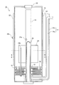
- FIG. 1 is a diagram illustrating an example of a reaction apparatus to which the present embodiment is applied.
- the reactor 10 shown in FIG. 1 includes an outer cylinder 12 that performs a reaction inside, a double pipe 14 that circulates a gas to be treated and a treated gas, and one of the outer cylinders 12 connected to the double pipe 14.
- the outer cylinder 12 is a reaction container, and a predetermined reaction can be performed inside.
- a gas containing a fluorine compound is circulated inside the outer cylinder 12 as the gas to be processed.
- a reaction agent is filled between the outer cylinder 12 and the inner cylinder 18, and the reaction which decomposes
- the fluorine compound include chlorofluorocarbons (hereinafter abbreviated as “CFC”), hydrochlorofluorocarbons (hereinafter abbreviated as “HCFC”), perfluorocarbons (hereinafter abbreviated as “PFC”), and the like.
- Hydrofluorocarbons hereinafter abbreviated as “HFC”
- PFE perfluoroethers
- HFE hydrofluoroethers
- sulfur fluoride sulfur fluoride
- examples of the CFC include CClF 3 , CCl 2 F 2 , CCl 3 F, C 2 Cl 3 F 3 , C 2 Cl 2 F 4 , and C 2 ClF 5
- examples of the HCFC include CHClF. 2 , compounds such as C 2 HCl 2 F 3 and the like.
- Examples of PFC include compounds such as CF 4 , C 2 F 6 , C 3 F 8 , C 4 F 8 (octafluorocyclobutane)
- examples of HFC include CH 3 F, CH 2 F 2 , CHF 3 , C A compound such as 2 H 2 F 4 may be mentioned.
- Examples of PFE include compounds such as CF 3 OCF 3 and CF 3 OCF 2 CF 3
- examples of HFE include compounds such as CHF 2 OCHF 2 , CHF 2 OCH 2 CF 3 , and CH 3 OCF 2 CF 3
- sulfur fluoride include compounds such as SF 6 and S 2 F 10 .
- fluorine compounds may be used alone or as a mixture of two or more.
- the fluorine compound is preferably diluted with an inert gas such as helium, argon or nitrogen, or air as a carrier gas.
- the concentration of the fluorine compound in the gas to be treated is preferably 0.01 vol% to 10 vol%.
- the reactant examples include at least one metal compound selected from the group consisting of copper (Cu), tin (Sn), chromium (Cr), molybdenum (Mo), tungsten (W), and vanadium (V), and alumina. And those containing an alkaline earth metal compound can be used.
- alumina is a typical acidic substance (solid acid), which can decompose a fluorine compound alone.
- the surface of the alumina is fluorinated by the fluorine generated by decomposition, poisoned as AlF 3 , and the catalytic activity is deactivated in a short time.
- an alkaline earth metal compound is contained.
- the fluorine compound can be decomposed at a lower reaction temperature than before, and the generated fluorine can be immobilized as an alkaline earth metal fluoride. This will be described in more detail below.
- the decomposition reaction of the fluorine compound in the present embodiment can be expressed by the following formula, for example.
- the reaction temperature here varies depending on the type of fluorine compound contained in the gas to be treated.
- PFC is classified as a hardly decomposable compound among fluorine compounds.
- CF 4 , C 2 F 6, etc. are the most difficult decomposable, and a high temperature of 1200 ° C. to 1400 ° C. is necessary for decomposing only by thermal decomposition.
- it can be decomposed at 550 ° C. or higher.
- CHClF 2 which is HCFC can be decomposed at a temperature of 200 ° C. or higher according to the method of the present embodiment.
- the decomposition temperature varies widely, and it is important to set the reactor at the optimum temperature depending on the type of compound.
- an alkaline earth metal carbonate, hydroxide or oxide can be used as the alkaline earth metal compound.
- carbonates of magnesium (Mg), calcium (Ca), strontium (Sr), and barium (Ba) are more preferable
- calcium carbonate (CaCO 3 ) which is a carbonate of calcium, is more preferable.
- fluorine generated by decomposition of the fluorine compound can be fixed as calcium fluoride (CaF 2 ). For this reason, it plays the role which prevents the fluorination of an alumina, and can maintain the decomposition function (activity) of the fluorine compound of alumina.
- One of the components of the reactant is a metal compound selected from the group consisting of copper (Cu), tin (Sn), chromium (Cr), molybdenum (Mo), tungsten (W), and vanadium (V). Acts as a co-catalyst for decomposing fluorine compounds. Depending on the type of the fluorine compound, carbon monoxide generated by decomposition by the reaction exemplified in the above formula (2) can be oxidized to carbon dioxide even under a low oxygen partial pressure. Of the above compounds, oxides such as copper oxide (CuO), tin oxide (SnO 2 ), and vanadium oxide (V 2 O 5 ) are preferably used, and copper oxide and tin oxide are more preferably used.
- the content of alumina and the alkaline earth metal compound is preferably 1: 9 to 1: 1 by mass ratio.
- the content of the metal compound is preferably 1:99 to 5:95 in terms of the total mass of alumina and the alkaline earth metal compound.
- the reactant is made into a granular product having a particle size of 0.5 mm to 10 mm, and is filled in a space formed between the inner side of the outer cylinder 12 and the outer side of the inner cylinder 18.
- the filling amount is preferably 80% to 90% of the entire space.
- the part filled with this reactive agent becomes a reaction area
- the double tube 14 includes an inner tube 14a that is an inner tube and an outer tube 14b that is an outer tube. Then, the gas to be treated is circulated through either the inner pipe 14a or the outer pipe 14b, the treated gas is circulated through the other pipe, and between the gas to be treated and the treated gas through the inner pipe. The first heat exchange is performed. In this case, since the gas to be treated and the treated gas circulate opposite to each other, the double pipe 14 can also be regarded as a counter flow type double pipe heat exchanger. The gas to be treated may pass through either the inner pipe 14a or the outer pipe 14b, but it is preferable to pass through the inner pipe 14a from the viewpoint of the efficiency of this heat exchange.
- the heat exchanger 16 as the main heat exchange unit is disposed on one end side of the outer cylinder 12. And it connects to the double pipe 14, for example, to-be-processed gas is supplied to the heat exchanger 16 by the inner tube 14a, and processed gas is taken out from the heat exchanger 16 by the outer tube 14b.
- the second heat exchange is performed between the gas to be processed and the processed gas.
- the heat exchanger 16 when cylindrical ones are used for the outer cylinder 12 and the inner cylinder 18, the heat exchanger 16 superimposes and welds plates made of donut-shaped stainless steel, and the gas to be processed and the processed gas Circulate through different routes.
- the to-be-processed gas and the processed gas can distribute
- the gas to be processed and the processed gas are configured to reciprocate 2.5 times in the zigzag flow path at the portion where heat exchange is performed.
- Each zigzag flow path is preferably 1.5 reciprocations or more. If it is less than this, heat exchange is insufficient, and the exhaust gas temperature at the outlet of the apparatus tends to increase.
- the treated gas can enter the heat exchanger 16 through a plurality of small-diameter holes 30 formed on the reaction region on the heat exchanger 16 side. Further, the gas to be processed that has passed through the heat exchanger 16 can enter the inner cylinder 18 through a plurality of holes 32 formed in the side surface of the inner cylinder 18.
- the heat exchanger 16 is not limited to such a structure, and various heat exchangers such as a spiral heat exchanger, a plate heat exchanger, and a multi-tube heat exchanger may be used. Can do.
- the inner cylinder 18 is arranged inside the outer cylinder 12. And it connects to the heat exchanger 16, and it distribute
- the inner cylinder 18 is composed of one in the present embodiment, but may be two or more. Moreover, about the position of the inner cylinder 18, when comprised by 1 like this Embodiment, installing in the center part of the outer cylinder 12 is preferable.
- the inner cylinder 18 includes an internal heater 20 inside.
- the internal heater 20 further heats the gas to be processed and supplies heat necessary for the reaction to the reaction region inside the outer cylinder.
- a fin 24 is attached to the outside of the inner cylinder 18. Heat generated by the internal heater 20 is transferred to the reaction region through the inner cylinder 18 and the fins 24. Further, by providing the fins 24, heat generated by the internal heater 20 can be more uniformly transferred to the reaction region.
- the reaction apparatus 10 of the present embodiment is used with the side on which the heat exchanger 16 is disposed as the lower side, the fins 24 are attached to the lower half of the reaction region and attached to the upper half. Preferably not.
- the temperature of the upper part of the reaction region is likely to rise due to convection, and if the fins 24 are attached to this part, the temperature on the upper side is likely to be higher than the lower side. Therefore, the temperature distribution in the upper and lower portions of the reaction region can be made more uniform by attaching the lower half position.
- FIG. 2 is a cross-sectional view of the reactor 10 shown in FIG. 1 taken along the line II-II.
- 18 fins 24 are attached to the outside of the inner cylinder 18.
- an external heater 22 is provided outside the outer cylinder 12.
- heat necessary for the reaction in the reaction region can be supplied also from the outside.
- the heat generated by the external heater 22 is transferred to the reaction region through the outer cylinder 12.
- the external heater 24 for example, an Incoloy (registered trademark) heater can be used. From the viewpoint of supplying heat uniformly, it is preferable to install this Incoloy (registered trademark) heater around the outer cylinder 12. Further, in order to facilitate separation of the reaction device and the control device of the present embodiment in maintenance or the like, it is preferable to connect the heater and / or the temperature sensor and the control device with, for example, a metal outlet.
- a heat insulating material (not shown) in order to prevent heat radiation to the atmosphere and to heat the reaction region more efficiently.
- a heat retention agent what was comprised with materials, such as a glass cloth and a silicon cloth, can be used, for example.
- a gas containing a fluorine compound which is a gas to be treated, first circulates through the inner pipe 14b of the double pipe 14. At this time, the first heat exchange is performed between the gas to be processed and the processed gas.
- the heat exchanger 16 enters the heat exchanger 16 connected to the double pipe 14, flows through the heat exchanger 16, and performs second heat exchange with the treated gas again. Then, it enters the inner cylinder 18 connected to the heat exchanger 16.
- the gas to be processed is heated by the internal heater 20 while performing third heat exchange with the reaction region when flowing in the inner cylinder 18. After passing through the inner cylinder 18, it enters the reaction region, and the fluorine compound contained in the gas to be processed is decomposed by the processing agent.
- the gas to be processed becomes a processed gas.
- the treated gas then performs the second heat exchange and the first heat exchange described above with the gas to be treated while flowing through the heat exchanger 16 and the outer pipe 14b of the double pipe 14. Then, after passing through the double pipe 14, it is released into the atmosphere.
- the gas to be treated and the treated gas are circulated through the double pipe 14, the first heat exchange is performed between the gas to be treated and the treated gas, and the heat exchange connected to the double pipe 14.
- the gas to be treated and the treated gas are circulated through the vessel 16, the second heat exchange is performed between the gas to be treated and the treated gas, and the gas to be treated is circulated through the inner cylinder 18 connected to the heat exchanger 16.
- a reaction method characterized in that a third heat exchange is performed between the gas to be processed and the reaction region, and a reaction to convert the gas to be processed into a processed gas is performed in the reaction region.
- the reaction apparatus 10 of the present embodiment can integrate the outer cylinder 12 and the heat exchanger 16.
- a pipe for introducing the gas to be treated and the treated gas into the heat exchanger 16 is a double pipe 14. These structures facilitate the downsizing of the reactor 10.
- the gas to be treated can be sufficiently obtained by performing the three-stage heat exchange of the first heat exchange by the double pipe 14, the second heat exchange by the heat exchanger 16, and the third heat exchange by the inner cylinder 18. Preheated and hot enough to reach the reaction zone. For this reason, the temperature distribution in the reaction region is easily uniformized. Therefore, reaction unevenness is less likely to occur. In addition, when the temperature distribution in the reaction region is not uniform, the consumption of the reactant in the portion where the temperature is high may become severe. For this reason, when the lifetime of the reactant is reached in this part, it is necessary to replace all the reactants, which is uneconomical. In the reaction apparatus 10 of the present embodiment, the temperature distribution in the reaction region is easily uniformed, so that not only reaction unevenness is likely to occur, but also the consumption of the reactants is likely to be uniform, thereby extending the lifetime of the reactants. it can.
- it is more preferably 40 liters to 200 liters. Further, by having the above structure, it can be used as a reactor having a reaction temperature of 200 ° C. to 1000 ° C., and the gas temperature at the outlet of the reactor can be made 200 ° C. or less.
- a gas containing a fluorine compound is exemplified as the gas to be treated, and the reaction for decomposing the fluorine compound has been described.
- the present invention is not limited to this. If a gas other than a fluorine compound is used as the gas to be treated and the reactant is changed to a gas suitable for the reaction of this gas, the reactor 10 of the present embodiment can be applied.
- the reactor 10 of the present embodiment can be applied.
- it in order to decompose and remove nitrous oxide contained in a surplus anesthetic gas discharged from a purge gas line or an operating room in a semiconductor manufacturing apparatus, it can be used for a reaction using a solid catalyst as a reactant.
- the reaction apparatus 10 shown in FIGS. 1 and 2 was used as the reaction apparatus.
- the reactant alumina and calcium carbonate were used in a mass ratio of 3: 7, and tin oxide was used in an amount of 3% by mass based on the total weight of alumina and calcium carbonate.
- CF 4 which is a fluoride gas was circulated in the reactor 10 at a concentration of 6000 volppm and a flow rate of 250 L / min as a gas to be treated. Nitrogen gas was used as the carrier gas. As a result, the concentration of CF 4 in the treated gas was 0 ppm, and it was confirmed that CF 4 could be decomposed. At this time, the temperature distribution inside and outside the reactor 10 was measured.
- FIG. 3 is a diagram illustrating the temperature distribution of the reaction apparatus 10.
- the horizontal axis represents temperature
- the vertical axis represents the height direction position of the reaction region.
- the external temperature and internal temperature in each place were shown.
- the external temperature is a temperature measured by sequentially changing the height direction position of the temperature sensor 26c (see FIG. 1).
- the internal temperature is a temperature measured by sequentially changing the position in the height direction of the temperature sensor 26b (see FIG. 1).
- the internal temperature and the external temperature are within a temperature difference of approximately 30 ° C. within the range of 550 ° C. to 580 ° C. with respect to the height direction position of the reaction region, and uniform temperature distribution in the reaction region It can be seen that is realized.
- FIG. 2 is a II-II cross-sectional view of the reaction apparatus shown in FIG. It is a figure explaining the temperature distribution of the reactor.
Landscapes
- Engineering & Computer Science (AREA)
- Chemical & Material Sciences (AREA)
- Environmental & Geological Engineering (AREA)
- Chemical Kinetics & Catalysis (AREA)
- Analytical Chemistry (AREA)
- General Chemical & Material Sciences (AREA)
- Oil, Petroleum & Natural Gas (AREA)
- Health & Medical Sciences (AREA)
- Biomedical Technology (AREA)
- Treating Waste Gases (AREA)
- Physical Or Chemical Processes And Apparatus (AREA)
- Exhaust Gas Treatment By Means Of Catalyst (AREA)
- Organic Low-Molecular-Weight Compounds And Preparation Thereof (AREA)
- Heat-Exchange Devices With Radiators And Conduit Assemblies (AREA)
- Solid-Sorbent Or Filter-Aiding Compositions (AREA)
- Devices And Processes Conducted In The Presence Of Fluids And Solid Particles (AREA)
- Catalysts (AREA)
Abstract
Description
しかしながら、これらのフッ素化合物の中には、大気中に放出されると、地球環境に対し大きな影響を与えるものが多い。即ち、成層圏のオゾン層を破壊し、オゾンホールを作り出す原因となる。また温暖化ガスとして地球温暖化の一因ともなり得る。そして、上述のようにフッ素化合物は一般に安定であり、その影響は長期間続く場合が多い。
そこで、地球環境に影響を与えないために、使用されたフッ素化合物を分解し、地球環境に対し無害な状態にして大気中に放出する必要がある。
更に、外管と、内管と、内管の内部に設けられた触媒層と、外管に取り付けられたヒータとを有するフッ素含有化合物ガスの処理装置については、フッ素含有化合物ガスの予熱が十分行われないため、同様に処理装置内部の温度分布が一様になりにくい。そのため反応のムラが生じる問題がある。
また、他の目的は、被処理ガスを高い効率で処理することができる反応方法を提供することにある。
図1は、本実施の形態が適用される反応装置の一例を説明した図である。
図1に示した反応装置10は、内部にて反応を行う外筒12と、被処理ガスおよび処理済ガスを流通させる二重管14と、二重管14に接続し外筒12の一方の端部側に配され被処理ガスと処理済ガスとの間で熱交換を行う主熱交換部としての熱交換器16と、主熱交換部としての熱交換器16に接続し外筒12内部に配され、熱交換器16が配される端部側から離間した外筒12の他方の端部側に向けて被処理ガスを流通させる内筒18とを備える。
また、内筒18の内部に配され被処理ガスを更に加熱すると共に外筒内部の反応領域に反応に必要な熱を供給するための加熱器としての内部ヒータ20と、外筒12の外部に配され同様に外筒内部の反応領域に反応に必要な熱を供給するための加熱器としての外部ヒータ22と、内筒18の外側に取り付けられ内部ヒータ20からの熱を反応領域に均一に伝熱させるためのフィン24と、温度を測定し図示しない制御装置により反応装置10内部の温度制御を行うための熱電対等からなる温度センサ26a,26b,26cと、反応剤を充填するための反応剤投入口28とを更に備える。
フッ素化合物としては、例えば、クロロフルオロカーボン類(以下、「CFC」と略す。)、ハイドロクロロフルオロカーボン類(以下、「HCFC」と略す。)、パーフルオロカーボン類(以下、「PFC」と略す。)、ハイドロフルオロカーボン類(以下、「HFC」と略す。)、パーフルオロエーテル類(以下、「PFE」と略す。)、ハイドロフルオロエーテル類(以下、「HFE」と略す。)、フッ化硫黄等が該当する。
このうち、アルミナは、代表的な酸性物質(固体酸)であり、それ単独であってもフッ素化合物を分解できる。しかし、分解されて生成したフッ素によってアルミナ表面がフッ素化され、AlF3として被毒されて触媒活性が短時間で失活する。
まず本実施の形態におけるフッ素化合物の分解反応は、例えば以下の式で表すことができる。

上記化合物のうち、酸化銅(CuO)、酸化錫(SnO2)、酸化バナジウム(V2O5)などの酸化物を用いるのが好ましく、酸化銅、酸化錫を用いるのが更に好ましい。
本実施の形態において、外筒12と内筒18に円柱形状のものを用いた場合、熱交換器16は、ドーナツ形状のステンレスからなる板を重ね合わせて溶接し、被処理ガスと処理済ガスが別々の経路を通り、流通するようにしている。そして、被処理ガスと処理済ガスは、熱交換器16内部をジグザグに対向する形で流通し、ドーナツ形状の板を通して熱交換を行うことができる。このように、流路をジグザグにすることで、小さい容積で多量の熱を交換することができる。本実施の形態では、被処理ガスおよび処理済ガスは、熱交換を行う部分においてこのジグザグの流路をそれぞれ2.5往復するように構成している。このジグザグの流路はそれぞれ1.5往復以上であることが好ましい。これより少ないと熱交換が不足し本装置出口の排ガス温度が高くなる傾向がある。
なお、処理済ガスは、反応領域の熱交換器16側に複数開けられた小口径の孔30を通して、熱交換器16内部に侵入することができる。また熱交換器16を通り抜けた被処理ガスは、内筒18側面に開けられた複数の穴32を通して、内筒18内に侵入することができる。
図2は、図1に示した反応装置10のII-II断面図である。
図2に示した反応装置10では、フィン24は、内筒18の外側に18枚取り付けられている。このように複数枚取り付けることにより反応領域の温度分布をより均一化することができる。ここでフィン24の枚数や長さは、反応装置10における反応条件によって適宜選択することができる。
また、内部ヒータ20には、例えば、インコネル(登録商標)ヒータを使用することができる。そして、このインコネル(登録商標)ヒータを例えば3本用い、デルタ結線を行って内筒18の内部に収容することができる。
外部ヒータ24には、例えば、インコロイ(登録商標)ヒータを使用することができる。そして均一に熱を供給する観点から、このインコロイ(登録商標)ヒータを外筒12の周囲に設置することが好ましい。
また、メンテナンス等における本実施の形態の反応装置と制御装置との切り離しを容易にするため、ヒータおよび/または温度センサと制御装置とを、例えばメタルコンセントで接続することが好ましい。
このような反応は、二重管14に被処理ガスおよび処理済ガスを流通させ、被処理ガスと処理済ガスとの間で第1の熱交換を行い、二重管14に接続する熱交換器16に被処理ガスおよび処理済ガスを流通させ、被処理ガスと処理済ガスとの間で第2の熱交換を行い、熱交換器16に接続する内筒18に被処理ガスを流通させ、被処理ガスと反応領域との間で第3の熱交換を行い、反応領域で被処理ガスを処理済ガスにする反応を行うことを特徴とする反応方法として捉えることもできる。
外筒12と内筒18の間の空間容積つまり外筒内部の反応領域は、内部の温度の均一性の観点と強度の観点から2リットル~3000リットルであることが好ましい。また特に2リットル~200リットルであることが好ましい。この場合キャスター等を取り付けることが容易となり、反応装置10の交換作業の際に有利となる。そして内部の温度の均一性および反応効率の観点から、40リットル~200リットルであることが更に好ましい。
また上記の構造を有することで、反応温度が200℃~1000℃の反応装置として使用でき、かつ、反応装置出口のガス温度を200℃以下にすることができる。
例えば、半導体製造装置におけるパージガスラインや手術室から排出される余剰麻酔ガス中に含まれる亜酸化窒素を分解除去するため、反応剤として固体触媒を使用する反応等に用いることができる。
その結果、処理済ガスのCF4の濃度は0ppmとなり、CF4が分解できたことを確認した。また、この際に反応装置10の外部と内部の温度分布の測定を行った。
図3において、横軸は温度を表し、縦軸は反応領域の高さ方向位置を表している。そして、それぞれの場所における外部温度と内部温度を示した。ここで外部温度は、温度センサ26c(図1参照)の高さ方向位置を順次変更することで測定された温度である。また内部温度は温度センサ26b(図1参照)の高さ方向位置を順次変更することで測定された温度である。
図3からわかる通り、内部温度および外部温度は反応領域の高さ方向位置に対し、550℃~580℃の範囲内の概ね30℃以内の温度差に収まっており、反応領域における均一な温度分布が実現できていることがわかる。
Claims (10)
- 内部にて反応を行う外筒と、
前記外筒の一方の端部側に配され、被処理ガスと処理済ガスとの間で熱交換を行う主熱交換部と、
前記主熱交換部に前記被処理ガスを供給する管と、
前記主熱交換部から前記処理済ガスを取り出す管と、
前記主熱交換部に接続し、前記外筒の内部に配され、前記主熱交換部が配される端部側から離間した当該外筒の他方の端部側に向けて前記被処理ガスを流通させる内筒と、
を備えることを特徴とする反応装置。 - 前記被処理ガスは、フッ素化合物を含むことを特徴とする請求項1に記載の反応装置。
- 前記反応は、前記フッ素化合物を銅(Cu)、錫(Sn)、クロム(Cr)、モリブデン(Mo)、タングステン(W)、バナジウム(V)からなる群から選ばれる金属の化合物の少なくとも一種、アルミナおよびアルカリ土類金属化合物を含有する反応剤により分解するものであることを特徴とする請求項2に記載の反応装置。
- 前記反応は、前記外筒と前記内筒との間で行うことを特徴とする請求項1乃至3の何れか1項に記載の反応装置。
- 内部の反応領域にて反応を行う外筒と、
被処理ガスおよび処理済ガスを流通させ、当該被処理ガスと当該処理済ガスとの間で第1の熱交換を行う二重管と、
前記二重管に接続し、前記被処理ガスと前記処理済ガスとの間で第2の熱交換を行う熱交換器と、
前記熱交換器に接続し、前記外筒の内部に配され、被処理ガスと前記反応領域との間で第3の熱交換を行う内筒と、
を備えることを特徴とする反応装置。 - 前記内筒の内部および前記外筒の外部に配される加熱器を更に備えることを特徴とする請求項5に記載の反応装置。
- 前記内筒の外側に取り付けられるフィンを更に備えることを特徴とする請求項5または6に記載の反応装置。
- 前記フィンは、前記反応領域の下側半分の位置に取り付けられることを特徴とする請求項7に記載の反応装置。
- 二重管に被処理ガスおよび処理済ガスを流通させ、当該被処理ガスと当該処理済ガスとの間で第1の熱交換を行い、
前記二重管に接続する熱交換器に被処理ガスおよび処理済ガスを流通させ、当該被処理ガスと当該処理済ガスとの間で第2の熱交換を行い、
前記熱交換器に接続する内筒に被処理ガスを流通させ、被処理ガスと反応領域との間で第3の熱交換を行い、
前記反応領域で被処理ガスを処理済ガスにする反応を行うことを特徴とする反応方法。 - 前記被処理ガスは、フッ素化合物を含むガスであり、前記反応は当該フッ素化合物を分解するものであることを特徴とする請求項9に記載の反応方法。
Priority Applications (2)
| Application Number | Priority Date | Filing Date | Title |
|---|---|---|---|
| JP2011502732A JPWO2010101073A1 (ja) | 2009-03-04 | 2010-02-25 | 反応装置および反応方法 |
| CN201080004458.4A CN102281939B (zh) | 2009-03-04 | 2010-02-25 | 反应装置和反应方法 |
Applications Claiming Priority (2)
| Application Number | Priority Date | Filing Date | Title |
|---|---|---|---|
| JP2009050533 | 2009-03-04 | ||
| JP2009-050533 | 2009-03-04 |
Publications (1)
| Publication Number | Publication Date |
|---|---|
| WO2010101073A1 true WO2010101073A1 (ja) | 2010-09-10 |
Family
ID=42709632
Family Applications (1)
| Application Number | Title | Priority Date | Filing Date |
|---|---|---|---|
| PCT/JP2010/052988 WO2010101073A1 (ja) | 2009-03-04 | 2010-02-25 | 反応装置および反応方法 |
Country Status (4)
| Country | Link |
|---|---|
| JP (2) | JPWO2010101073A1 (ja) |
| CN (1) | CN102281939B (ja) |
| TW (1) | TW201111030A (ja) |
| WO (1) | WO2010101073A1 (ja) |
Cited By (4)
| Publication number | Priority date | Publication date | Assignee | Title |
|---|---|---|---|---|
| WO2015057752A1 (en) * | 2013-10-16 | 2015-04-23 | Saudi Basic Industries Corporation | Purification of carbon dioxide streams |
| US9850136B2 (en) | 2013-10-16 | 2017-12-26 | Saudi Basic Industries Corporation | Catalyst for purification of CO2 from chlorinated hydrocarbons |
| WO2021060145A1 (ja) * | 2019-09-27 | 2021-04-01 | 住友化学株式会社 | 化学反応方法および化学反応装置 |
| CN113244874A (zh) * | 2021-05-11 | 2021-08-13 | 李佩瑶 | 一种消毒液生产用温控装置及消毒液生产质量监控系统 |
Citations (5)
| Publication number | Priority date | Publication date | Assignee | Title |
|---|---|---|---|---|
| JPS6451126U (ja) * | 1987-09-22 | 1989-03-29 | ||
| JP2001219031A (ja) * | 2000-02-08 | 2001-08-14 | Air Liquide Japan Ltd | パーフルオロ化合物の分解方法及び分解装置 |
| JP2003144843A (ja) * | 2001-11-13 | 2003-05-20 | Japan Pionics Co Ltd | フッ化硫黄の分解処理剤及び分解処理方法 |
| JP2004000920A (ja) * | 2002-03-26 | 2004-01-08 | Showa Denko Kk | 反応装置及び反応方法 |
| JP2008126092A (ja) * | 2006-11-16 | 2008-06-05 | Ube Ind Ltd | フッ素含有化合物ガスの処理装置および処理方法 |
Family Cites Families (4)
| Publication number | Priority date | Publication date | Assignee | Title |
|---|---|---|---|---|
| JPS6451126A (en) * | 1987-08-20 | 1989-02-27 | Mitsubishi Heavy Ind Ltd | High temperature catalyst device |
| JP3789277B2 (ja) * | 1999-04-28 | 2006-06-21 | 昭和電工株式会社 | フッ素化合物の分解用反応剤、分解方法及びその用途 |
| TW590792B (en) * | 2002-03-26 | 2004-06-11 | Showa Denko Kk | Reaction device with a heat-exchanger |
| WO2004067152A1 (en) * | 2003-01-29 | 2004-08-12 | Showa Denko K. K. | Process for decomposing fluorine compounds |
-
2010
- 2010-02-25 WO PCT/JP2010/052988 patent/WO2010101073A1/ja active Application Filing
- 2010-02-25 JP JP2011502732A patent/JPWO2010101073A1/ja active Pending
- 2010-02-25 CN CN201080004458.4A patent/CN102281939B/zh active Active
- 2010-03-04 TW TW99106334A patent/TW201111030A/zh unknown
-
2015
- 2015-01-21 JP JP2015009446A patent/JP5848468B2/ja active Active
Patent Citations (5)
| Publication number | Priority date | Publication date | Assignee | Title |
|---|---|---|---|---|
| JPS6451126U (ja) * | 1987-09-22 | 1989-03-29 | ||
| JP2001219031A (ja) * | 2000-02-08 | 2001-08-14 | Air Liquide Japan Ltd | パーフルオロ化合物の分解方法及び分解装置 |
| JP2003144843A (ja) * | 2001-11-13 | 2003-05-20 | Japan Pionics Co Ltd | フッ化硫黄の分解処理剤及び分解処理方法 |
| JP2004000920A (ja) * | 2002-03-26 | 2004-01-08 | Showa Denko Kk | 反応装置及び反応方法 |
| JP2008126092A (ja) * | 2006-11-16 | 2008-06-05 | Ube Ind Ltd | フッ素含有化合物ガスの処理装置および処理方法 |
Cited By (6)
| Publication number | Priority date | Publication date | Assignee | Title |
|---|---|---|---|---|
| WO2015057752A1 (en) * | 2013-10-16 | 2015-04-23 | Saudi Basic Industries Corporation | Purification of carbon dioxide streams |
| US9850136B2 (en) | 2013-10-16 | 2017-12-26 | Saudi Basic Industries Corporation | Catalyst for purification of CO2 from chlorinated hydrocarbons |
| US10005673B2 (en) | 2013-10-16 | 2018-06-26 | Saudi Basic Industries Corporation | Purification of carbon dioxide streams |
| WO2021060145A1 (ja) * | 2019-09-27 | 2021-04-01 | 住友化学株式会社 | 化学反応方法および化学反応装置 |
| CN114423515A (zh) * | 2019-09-27 | 2022-04-29 | 住友化学株式会社 | 化学反应方法及化学反应装置 |
| CN113244874A (zh) * | 2021-05-11 | 2021-08-13 | 李佩瑶 | 一种消毒液生产用温控装置及消毒液生产质量监控系统 |
Also Published As
| Publication number | Publication date |
|---|---|
| JP2015116568A (ja) | 2015-06-25 |
| CN102281939B (zh) | 2014-02-26 |
| CN102281939A (zh) | 2011-12-14 |
| JPWO2010101073A1 (ja) | 2012-09-10 |
| TW201111030A (en) | 2011-04-01 |
| JP5848468B2 (ja) | 2016-01-27 |
Similar Documents
| Publication | Publication Date | Title |
|---|---|---|
| JP5848468B2 (ja) | 反応装置 | |
| JP3713333B2 (ja) | 弗化炭素類の分解法 | |
| TW200829325A (en) | Apparatus and method for processing gas | |
| US6630421B1 (en) | Reactive agent and process for decomposing fluorine compounds and use thereof | |
| CN1195573C (zh) | 用于分解氟化合物的反应剂和方法及其用途 | |
| US5707595A (en) | Method and apparatus for use in photochemically oxidizing gaseous volatile or semi-volatile organic compounds | |
| JP3249986B2 (ja) | フロンの分解処理法および装置 | |
| JP4873147B2 (ja) | フッ素含有化合物ガスの処理装置および処理方法 | |
| JP3592886B2 (ja) | 弗化炭素類の分解方法および分解用反応剤 | |
| JP4264076B2 (ja) | 弗化炭素類の分解装置 | |
| JP2001219031A (ja) | パーフルオロ化合物の分解方法及び分解装置 | |
| KR100939307B1 (ko) | 불소-함유 화합물을 함유하는 배기 가스의 처리 방법 및장치 | |
| JP4714620B2 (ja) | オゾンガス分解装置および処理システム | |
| JP5066021B2 (ja) | Pfc処理装置及びpfc含有ガスの処理方法 | |
| JP5294553B2 (ja) | 炭素含有アルカリ土類金属酸化物の製造方法および有機ハロゲン化物の分解処理方法 | |
| JP4480949B2 (ja) | 反応装置及び反応方法 | |
| JP2010158620A (ja) | フッ素化合物を含有する排ガスの処理方法及び処理用反応槽 | |
| JP4698201B2 (ja) | フッ素含有ガス分解処理装置、及びこれを用いたフッ素化合物回収方法 | |
| JP2010058063A (ja) | フッ化物ガスの分解処理方法、分解処理剤及び分解処理装置 | |
| KR100968089B1 (ko) | 불소화합물 가스의 흡착처리제, 그를 이용한 불소화합물 가스 처리방법 및 불소화합물 가스 처리장치 | |
| JP5529374B2 (ja) | ガスの化学的処理方法 | |
| JP4509514B2 (ja) | 汚染物質ガスの分解装置および汚染土壌の処理装置 | |
| JP3570136B2 (ja) | 有機ハロゲン化合物含有ガスの処理方法及び有機ハロゲン化合物分解触媒 | |
| JP2000296324A (ja) | フッ化窒素の分解用反応剤及び分解法 | |
| JP5016618B2 (ja) | Sf6を含む排ガスの処理方法 |
Legal Events
| Date | Code | Title | Description |
|---|---|---|---|
| WWE | Wipo information: entry into national phase |
Ref document number: 201080004458.4 Country of ref document: CN |
|
| 121 | Ep: the epo has been informed by wipo that ep was designated in this application |
Ref document number: 10748668 Country of ref document: EP Kind code of ref document: A1 |
|
| ENP | Entry into the national phase |
Ref document number: 2011502732 Country of ref document: JP Kind code of ref document: A |
|
| NENP | Non-entry into the national phase |
Ref country code: DE |
|
| 122 | Ep: pct application non-entry in european phase |
Ref document number: 10748668 Country of ref document: EP Kind code of ref document: A1 |