WO2010100976A1 - 複合機能レーダ装置 - Google Patents
複合機能レーダ装置 Download PDFInfo
- Publication number
- WO2010100976A1 WO2010100976A1 PCT/JP2010/050888 JP2010050888W WO2010100976A1 WO 2010100976 A1 WO2010100976 A1 WO 2010100976A1 JP 2010050888 W JP2010050888 W JP 2010050888W WO 2010100976 A1 WO2010100976 A1 WO 2010100976A1
- Authority
- WO
- WIPO (PCT)
- Prior art keywords
- signal
- target object
- transmission signal
- unit
- transmission
- Prior art date
- Legal status (The legal status is an assumption and is not a legal conclusion. Google has not performed a legal analysis and makes no representation as to the accuracy of the status listed.)
- Ceased
Links
Images





Classifications
-
- G—PHYSICS
- G01—MEASURING; TESTING
- G01S—RADIO DIRECTION-FINDING; RADIO NAVIGATION; DETERMINING DISTANCE OR VELOCITY BY USE OF RADIO WAVES; LOCATING OR PRESENCE-DETECTING BY USE OF THE REFLECTION OR RERADIATION OF RADIO WAVES; ANALOGOUS ARRANGEMENTS USING OTHER WAVES
- G01S7/00—Details of systems according to groups G01S13/00, G01S15/00, G01S17/00
- G01S7/02—Details of systems according to groups G01S13/00, G01S15/00, G01S17/00 of systems according to group G01S13/00
- G01S7/35—Details of non-pulse systems
-
- G—PHYSICS
- G01—MEASURING; TESTING
- G01S—RADIO DIRECTION-FINDING; RADIO NAVIGATION; DETERMINING DISTANCE OR VELOCITY BY USE OF RADIO WAVES; LOCATING OR PRESENCE-DETECTING BY USE OF THE REFLECTION OR RERADIATION OF RADIO WAVES; ANALOGOUS ARRANGEMENTS USING OTHER WAVES
- G01S13/00—Systems using the reflection or reradiation of radio waves, e.g. radar systems; Analogous systems using reflection or reradiation of waves whose nature or wavelength is irrelevant or unspecified
- G01S13/02—Systems using reflection of radio waves, e.g. primary radar systems; Analogous systems
- G01S13/06—Systems determining position data of a target
- G01S13/08—Systems for measuring distance only
- G01S13/32—Systems for measuring distance only using transmission of continuous waves, whether amplitude-, frequency-, or phase-modulated, or unmodulated
- G01S13/34—Systems for measuring distance only using transmission of continuous waves, whether amplitude-, frequency-, or phase-modulated, or unmodulated using transmission of continuous, frequency-modulated waves while heterodyning the received signal, or a signal derived therefrom, with a locally-generated signal related to the contemporaneously transmitted signal
- G01S13/343—Systems for measuring distance only using transmission of continuous waves, whether amplitude-, frequency-, or phase-modulated, or unmodulated using transmission of continuous, frequency-modulated waves while heterodyning the received signal, or a signal derived therefrom, with a locally-generated signal related to the contemporaneously transmitted signal using sawtooth modulation
-
- G—PHYSICS
- G01—MEASURING; TESTING
- G01S—RADIO DIRECTION-FINDING; RADIO NAVIGATION; DETERMINING DISTANCE OR VELOCITY BY USE OF RADIO WAVES; LOCATING OR PRESENCE-DETECTING BY USE OF THE REFLECTION OR RERADIATION OF RADIO WAVES; ANALOGOUS ARRANGEMENTS USING OTHER WAVES
- G01S13/00—Systems using the reflection or reradiation of radio waves, e.g. radar systems; Analogous systems using reflection or reradiation of waves whose nature or wavelength is irrelevant or unspecified
- G01S13/86—Combinations of radar systems with non-radar systems, e.g. sonar, direction finder
-
- G—PHYSICS
- G01—MEASURING; TESTING
- G01S—RADIO DIRECTION-FINDING; RADIO NAVIGATION; DETERMINING DISTANCE OR VELOCITY BY USE OF RADIO WAVES; LOCATING OR PRESENCE-DETECTING BY USE OF THE REFLECTION OR RERADIATION OF RADIO WAVES; ANALOGOUS ARRANGEMENTS USING OTHER WAVES
- G01S13/00—Systems using the reflection or reradiation of radio waves, e.g. radar systems; Analogous systems using reflection or reradiation of waves whose nature or wavelength is irrelevant or unspecified
- G01S13/88—Radar or analogous systems specially adapted for specific applications
- G01S13/93—Radar or analogous systems specially adapted for specific applications for anti-collision purposes
- G01S13/937—Radar or analogous systems specially adapted for specific applications for anti-collision purposes of marine craft
-
- G—PHYSICS
- G01—MEASURING; TESTING
- G01S—RADIO DIRECTION-FINDING; RADIO NAVIGATION; DETERMINING DISTANCE OR VELOCITY BY USE OF RADIO WAVES; LOCATING OR PRESENCE-DETECTING BY USE OF THE REFLECTION OR RERADIATION OF RADIO WAVES; ANALOGOUS ARRANGEMENTS USING OTHER WAVES
- G01S7/00—Details of systems according to groups G01S13/00, G01S15/00, G01S17/00
- G01S7/02—Details of systems according to groups G01S13/00, G01S15/00, G01S17/00 of systems according to group G01S13/00
- G01S7/41—Details of systems according to groups G01S13/00, G01S15/00, G01S17/00 of systems according to group G01S13/00 using analysis of echo signal for target characterisation; Target signature; Target cross-section
- G01S7/411—Identification of targets based on measurements of radar reflectivity
- G01S7/412—Identification of targets based on measurements of radar reflectivity based on a comparison between measured values and known or stored values
-
- G—PHYSICS
- G01—MEASURING; TESTING
- G01S—RADIO DIRECTION-FINDING; RADIO NAVIGATION; DETERMINING DISTANCE OR VELOCITY BY USE OF RADIO WAVES; LOCATING OR PRESENCE-DETECTING BY USE OF THE REFLECTION OR RERADIATION OF RADIO WAVES; ANALOGOUS ARRANGEMENTS USING OTHER WAVES
- G01S13/00—Systems using the reflection or reradiation of radio waves, e.g. radar systems; Analogous systems using reflection or reradiation of waves whose nature or wavelength is irrelevant or unspecified
- G01S13/02—Systems using reflection of radio waves, e.g. primary radar systems; Analogous systems
- G01S13/50—Systems of measurement based on relative movement of target
- G01S13/58—Velocity or trajectory determination systems; Sense-of-movement determination systems
- G01S13/588—Velocity or trajectory determination systems; Sense-of-movement determination systems deriving the velocity value from the range measurement
Definitions
- the present invention relates to a radar apparatus, and more particularly, to a multi-function radar apparatus having a plurality of functions.
- a radar apparatus that measures a distance to a target object based on a beat signal generated by transmitting a frequency-modulated transmission signal to a target object and mixing the reflected wave and the transmission signal ( Patent Document 1).
- Patent Document 1 all objects having temperature naturally radiate infrared rays, and higher temperature objects radiate infrared rays more strongly.
- an infrared thermometer or the like that measures the temperature of the target object by receiving the infrared ray radiated from the target object and analyzing the intensity of the received infrared ray is known.
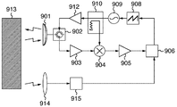
- FIG. 9 shows a conventional measuring apparatus having a function of measuring the distance to the target object and the temperature of the target object.
- a conventional measuring apparatus includes a transmission / reception antenna unit 901, a circulator unit 902, a reception signal amplification unit 903, a frequency conversion unit 904, a beat signal amplification unit 905, a signal processing unit 906, a frequency modulation signal generation unit 908, and a high frequency signal generation unit 909.
- a high-frequency signal branching unit 910, a transmission signal amplifying unit 912, an infrared receiving lens unit 914, and an infrared thermometer unit 915 are provided.
- the high frequency signal generated from the high frequency signal generation unit 909 is frequency-modulated by the control voltage output from the frequency modulation signal generation unit 908 based on the control of the signal processing unit 906 and output as a transmission signal. .
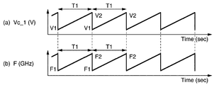
- FIG. 10A and 10B are schematic diagrams of control by a control voltage of a conventional measuring apparatus, in which FIG. 10A is a schematic of the control voltage of the frequency modulation signal generator 908, and FIG. 10B is the frequency of the high-frequency signal generator 909. It is an outline.
- the control voltage output from the frequency modulation signal generation unit 908 under the control of the signal processing unit 906 repeats changing from the voltage V1 to V2 during the time T1 every time T1. .
- the high-frequency signal generated by the high-frequency signal generator 909 changes from the frequency F1 to F2 during the time T1, according to the change of the control voltage of the frequency modulation signal generator 908, as shown in FIG. Is repeated every time T1.
- the high-frequency signal generator 909 continuously outputs transmission signals that are frequency-modulated by the control voltage from the frequency-modulated signal generator 908.
- the transmission signal output from the high-frequency signal generation unit 909 is branched by the high-frequency branching unit 910, power amplified by the transmission signal amplification unit 912, and transmitted from the transmission / reception antenna unit 901 via the circulator unit 902. Radiated toward 913.
- the reflected wave from the target object 913 is input to the transmission / reception antenna unit 901 by the radiation of the transmission signal.
- the reflected wave from the target object 913 is output from the transmission / reception antenna unit 901 as a reception signal, amplified by the reception signal amplification unit 903 via the circulator unit 902, and output to the frequency conversion unit 904.
- the frequency conversion unit 904 the transmission signal and the reception signal branched by the high frequency branching unit 910 are mixed and a beat signal is output.
- the output beat signal is amplified by the beat signal amplifier 905 and output to the signal processor 906.
- the signal processing unit 906 calculates the distance to the target object based on the beat signal.
- the infrared rays radiated from the target object 913 are received by the infrared light receiving lens unit 914 and output to the infrared thermometer unit 915.
- the infrared thermometer unit 915 analyzes the intensity of infrared rays and outputs an analysis signal to the signal processing unit 906.
- the signal processing unit 906 obtains the temperature distribution of the target object 913 based on the analysis signal, and calculates the temperature of the target object from the average value.
- the direction and focus of the transmission / reception antenna unit 901 and the infrared light receiving lens unit 914 must be adjusted to the target object 913. There is. At this time, a structure for adjusting the angle of the transmission / reception antenna unit 901 and the infrared light receiving lens unit 914 in the vertical and horizontal directions is necessary. However, depending on the structure of the measurement apparatus and the measurement location, the transmission / reception antenna unit 901 is sufficiently The angle with the infrared light receiving lens unit 914 may not be adjusted.
- the transmission signal radiated from the transmission / reception antenna unit 901 is unnecessarily reflected by the infrared light reception lens unit 914, or the infrared light from the target object 913 is reflected. There is a possibility that the signal is blocked by the transmission / reception antenna unit 901 and not sufficiently input to the infrared light receiving lens unit 914.
- the present invention has been made in view of the above problems, and an object thereof is to provide a multi-function radar device that can measure both the distance to the target object and the temperature of the target object with high accuracy.
- the multi-function radar device includes a high-frequency signal generating unit that outputs a frequency-modulated transmission signal, an antenna that radiates the transmission signal to a target object, and receives measurement information about the target object as a reception signal;
- a multi-function radar apparatus comprising: a frequency conversion unit that generates a beat signal by mixing the transmission signal and the reception signal; and a signal processing unit that performs measurement on the target object based on the beat signal.
- a transmission signal intermittent stop means for intermittently radiating the transmission signal, and the antenna receives a reflected wave from the target object as the measurement information while radiating the transmission signal, and transmits the transmission signal.
- the radiated wave from the target object is received as the measurement information, and the signal processing means, while the transmission signal is radiated, Based on the serial beat signal measures the distance to the target object, while the transmission signal is not emitted, and measuring the temperature of the target object based on the beat signal.
- both the distance to the target object and the temperature of the target object can be measured with high accuracy.
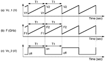
- FIG. 2 is a schematic diagram of control by a control voltage of the multi-function radar device according to the first embodiment of the present invention, where (a) is an outline of a control voltage of a frequency modulation signal generator, and (b) is a high-frequency signal generation. (C) is the outline of the control voltage of the intermittent stop signal generator. It is a block diagram which shows the function of the multifunctional radar apparatus which concerns on the 2nd Embodiment of this invention.
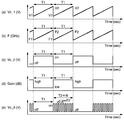
- FIG. 6 is a schematic diagram of control by a control voltage of a multi-function radar device according to a second embodiment of the present invention, where (a) is an outline of a control voltage of a frequency modulation signal generator, and (b) is a high-frequency signal generation. (C) is an outline of the control voltage of the intermittent stop signal generator, and (d) is an outline of the gain of the gain adjuster. It is a block diagram which shows the function of the multifunctional radar apparatus which concerns on the 3rd Embodiment of this invention.
- ⁇ First Embodiment> 1 includes a signal processing unit 6, a frequency modulation signal generation unit 8, a high frequency signal generation unit 9, a high frequency signal branch unit 10, an intermittent stop signal generation unit 7, a transmission intermittent stop switch 11, and a transmission signal amplification.
- a unit 12, a circulator unit 2, a transmission / reception antenna unit 1, a reception signal amplification unit 3, a frequency conversion unit 4, and a beat signal amplification unit 5 are provided.
- the frequency modulation signal generator 8 outputs a control voltage for frequency modulation to the high frequency signal generator 9 under the control of the signal processor 6.
- the high frequency signal generation unit 9 generates a high frequency signal and outputs a high frequency signal frequency-modulated by the control voltage output from the frequency modulation signal generation unit 8 as a transmission signal.
- the transmission signal output from the high frequency signal generation unit 9 is branched by the high frequency signal branching unit 10 and output to the transmission intermittent stop switch 11 and the frequency conversion unit 4.
- the transmission intermittent stop switch 11 receives a control voltage from the intermittent stop signal generation unit 7 under the control of the signal processing unit 6.
- the transmission intermittent stop switch 11 outputs or does not output the transmission signal output from the high-frequency signal branching unit 10 to the transmission signal amplifying unit 12 according to the control voltage output from the intermittent stop signal generating unit 7. Switch the signal path.
- the transmission signal input to the transmission intermittent stop switch 11 is intermittently output to the transmission signal amplifying unit 12 according to the connection state of the transmission intermittent stop switch 11.
- the transmission signal input to the transmission signal amplification unit 12 is amplified in power and radiated from the transmission / reception antenna unit 1 toward the target object 13 via the circulator unit 2.
- the radiated transmission signal is reflected by the target object 13, and the reflected wave is input to the transmission / reception antenna unit 1.
- the reflected wave input to the transmission / reception antenna unit 1 is output as a reception signal to the circulator unit 2, output to the reception signal amplification unit 3 by the circulator unit 2, amplified by the reception signal amplification unit 3, and output to the frequency conversion unit 4. Is done.
- the frequency conversion unit 4 mixes the transmission signal output from the high-frequency signal branching unit 10 and the reception signal output from the reception signal amplification unit 3, and generates a beat signal that is a difference signal between the transmission signal and the reception signal. Generate.
- the generated beat signal is amplified by the beat signal amplifying unit 5 and output to the signal processing unit 6.
- the signal processing unit 6 calculates the distance to the target object 13 based on the beat signal output from the beat signal amplification unit 5.
- the transmission / reception antenna unit 1 outputs a received signal to the circulator unit 2 when receiving a radiated wave from the target object 13 while not transmitting a transmission signal.
- the reception signal input to the circulator unit 2 is amplified by the reception signal amplification unit 3 and then mixed with the transmission signal branched from the high frequency signal branching unit 10 in the frequency conversion unit 4.
- the beat signal generated by mixing the transmission signal and the reception signal in the frequency conversion unit 4 is amplified by the beat signal amplification unit 5 and output to the signal processing unit 6.
- the signal processing unit 6 calculates the temperature of the target object 13 based on the beat signal output from the beat signal amplification unit 5.
- both the distance to the target object 13 and the temperature of the target object 13 can be measured by intermittently stopping the transmission of the high-frequency signal.
- the relationship between the control voltage of the frequency modulation signal generator 8, the frequency modulation of the high frequency signal generator 9, and the control voltage of the intermittent stop signal generator 7 in the present embodiment will be described with reference to FIG.
- FIG. 2A shows the control voltage of the frequency modulation signal generator 8.
- the control voltage of the frequency modulation signal generator 8 changes from voltage V1 to V2 during time T1, returns to voltage V1 when changed to voltage V2, and changes from voltage V1 to V2 again during the next time T1. repeat.
- FIG. 2B shows frequency modulation of the high-frequency signal generator 9. Since the frequency of the high-frequency signal generator 9 is frequency-modulated by the control voltage of the frequency-modulated signal generator 8, the time T1 is changed according to the change of the control voltage of the frequency-modulated signal generator 8 from the voltage V1 to V2. In the meantime, the frequency changes from F1 to F2.
- FIG. 2C shows the control voltage of the intermittent stop signal generator 7.
- the control voltage of the intermittent stop signal generator 7 is “ON” or “OFF” every time T1, and is kept “ON” or “OFF” during each time T1.
- the connection state of the transmission intermittent stop switch 11 is controlled to output the transmission signal output from the high-frequency signal generator 10 to the transmission signal amplifier 12.
- the control voltage of the intermittent stop signal generator 7 is “OFF”
- the connection state of the transmission intermittent stop switch 11 is controlled not to output the transmission signal output from the high frequency signal generator 10 to the transmission signal amplifier 12. Is done.
- the high frequency signal reflected from the target object 13 is received and the target object 13 is received while the high frequency signal is being transmitted.
- the temperature of the target object 13 can be measured by receiving the radiated wave radiated from the target object 13 while the high frequency signal is not transmitted. Therefore, since both the distance to the target object 13 and the temperature of the target object 13 can be measured with one transmission / reception antenna unit 1, there is little radio wave interference when measuring the target object 13, and the distance to the target object 13 and the target object are reduced. Both of the 13 temperatures can be measured with high accuracy.
- a gain adjustment unit 300 is provided instead of the reception signal amplification unit 3 in the first embodiment.
- Components having the same functions as those of the first embodiment are denoted by the same reference numerals and description thereof is omitted.
- the gain adjusting unit 300 includes a first received signal switching switch 301, a first received signal amplifying unit 302, a second received signal amplifying unit 303, a second received signal switching switch 304, and a gain switching signal generating unit 305.
- the first received signal amplifying unit 302 and the second received signal amplifying unit 303 are preset so as to have different gains.
- the gain of the second received signal amplifying unit 303 is the first received signal amplifying unit.
- the gain is set to be higher than the gain of the unit 302.
- the control voltage from the gain switching signal generation unit 305 under the control of the signal processing unit 6 is input to the first reception signal switching switch 301 and the second reception signal switching switch 304.
- the gain switching signal generation unit 305 outputs a control voltage that is “ON” to the first reception signal switching switch 301 and the second reception signal switching switch 304 while the transmission signal is radiated, and the transmission signal is radiated. While not being performed, a control voltage which is “OFF” is output.
- the first reception signal changeover switch 301 When a control voltage that is “ON” is output, the first reception signal changeover switch 301 is connected to the first reception signal amplification unit 302 and outputs the reception signal from the circulator unit 2 to the first reception signal amplification unit 302. To do.
- the second reception signal changeover switch 304 when a control voltage that is “ON” is output, the second reception signal changeover switch 304 is connected to the first reception signal amplification unit 302, and the reception signal from the first reception signal amplification unit 302 is converted to a frequency conversion unit. 4 is output.
- the first reception signal changeover switch 301 is connected to the second reception signal amplification unit 303, and the reception signal from the circulator unit 2 is transmitted to the second reception signal amplification unit 303.
- the second reception signal changeover switch 304 is connected to the second reception signal amplifying unit 303 when the control voltage to be “OFF” is output, and the received signal from the second reception signal amplifying unit 303 is converted to the frequency conversion unit. 4 is output.
- the reception signal received by the transmission / reception antenna unit 1 and output from the circulator unit 2 is switched to the first reception signal switching according to the control voltage from the gain switching signal generation unit 305.
- the signal is output from the switch 301 to the first reception signal amplification unit 302, amplified by the first reception signal amplification unit 302, and output to the frequency conversion unit 4 via the second reception signal changeover switch 304.
- the reception signal received by the transmission / reception antenna unit 1 and output from the circulator unit 2 is a first reception signal switch according to the control voltage from the gain switching signal generation unit 305.
- 301 is output to the second received signal amplifying unit 303, amplified by the second received signal amplifying unit 303, and output to the frequency converting unit 4 via the second received signal switching switch 304.
- the received signal composed of the radiated wave of the target object 13 is weaker than the received signal composed of the reflected wave of the target object 13.
- the gain adjustment unit 300 amplifies the received signal composed of the radiated wave of the target object 13 more greatly than the received signal composed of the reflected wave of the target object 13, the sensitivity for temperature measurement can be improved.
- FIG. 4 shows the relationship between the control voltage of the frequency modulation signal generator 8, the frequency modulation of the high frequency signal generator 9, the control voltage of the intermittent stop signal generator 7, and the gain of the gain adjuster 300 in this embodiment. It is shown.
- FIG. 4A shows the control voltage of the frequency modulation signal generator 8
- FIG. 4B shows the frequency modulation of the high frequency signal generator 9
- FIG. 4C shows the control voltage of the intermittent stop signal generator 7. Since these relationships are the same as those in FIG. 2 described in the first embodiment, description thereof is omitted.
- FIG. 4D shows a change in gain of the gain adjustment unit 300.
- the gain of the gain adjusting unit 300 is the first received signal amplification while the control voltage of the intermittent stop signal generating unit 7 shown in FIG. 4C is “ON”, that is, while the transmission signal is radiated. Since the received signal is amplified by the unit 302, it becomes low.
- the gain of the gain adjusting unit 300 is determined by the second received signal amplifying unit 303 while the control voltage of the intermittent stop signal generating unit 7 is “OFF”, that is, while the transmission signal is not transmitted. Will be amplified.
- the gain adjustment unit 300 by providing the gain adjustment unit 300, even if there is a difference in the level of the received signal, it can be amplified with a gain suitable for the level of each received signal. Can be improved.
- a measurement noise switching unit 200 is provided between the circulator unit 2 and the received signal amplification unit 3 in the first embodiment.
- Components having the same functions as those of the first embodiment are denoted by the same reference numerals and description thereof is omitted.
- the measurement noise switching unit 200 shown in FIG. 5 switches and outputs the radiation wave from the target object 13 and the thermal noise inside the multi-function radar device while the transmission signal is not transmitted.
- the measurement noise switching unit 200 includes a reception signal switching switch 201 and a measurement noise switching signal generation unit 202.
- a control voltage from the measurement noise switching signal generator 202 under the control of the signal processor 60 is input to the received signal selector switch 201.
- the reception signal changeover switch 201 outputs the reception signal output from the circulator unit 2 to the reception signal amplification unit 3 while the transmission signal is not transmitted according to the control voltage from the measurement noise switching signal generation unit 202. Alternatively, the signal path is switched so as not to output.
- the reception signal changeover switch 201 does not output the reception signal output from the circulator unit 2 to the reception signal amplification unit 3
- the thermal noise inside the multi-function radar device is output to the reception signal amplification unit 3 as a reception signal.
- the reception signal output from the measurement noise switching unit 200 is amplified by the signal amplification unit 3 and mixed with the transmission signal branched from the high frequency signal branching unit 10 by the frequency conversion unit 4.
- the beat signal generated based on the reception signal output from the measurement noise switching unit 200 and the transmission signal branched by the high frequency signal branching unit 10 is amplified by the beat signal amplification unit 5 and output to the signal processing unit 60. .
- the signal processing unit 60 compares the beat signal based on the thermal noise inside the multi-function radar device with the beat signal based on the radiation wave of the target object 13 and calculates the temperature of the target object 13.
- the radiation wave from the target object 13 and the inside of the multi-function radar device with reference to the thermal noise generated inside the multi-function radar device when the input of the receive signal amplifier 3 is terminated by the resistance of the receive signal switch 201.
- the accuracy of temperature measurement based on the radiation wave from the target object 13 can be improved by comparing the thermal noise of
- FIG. 6A shows the control voltage of the frequency modulation signal generator 8
- FIG. 6B shows the frequency modulation of the high frequency signal generator 9
- FIG. 6C shows the control voltage of the intermittent stop signal generator 7. Since these relationships are the same as those in FIG. 2 described in the first embodiment, description thereof is omitted.
- FIG. 6D shows the control voltage of the measurement noise switching signal generator 202.
- the control voltage of the measurement noise switching signal generation unit 202 becomes “ON” or “OFF” every time T2 while the control voltage of the intermittent stop signal generation unit 7 shown in FIG. 6C is “OFF”. Is repeated N times, and is kept “ON” or “OFF” for each time T2. Note that while the control voltage of the intermittent stop signal generator 7 shown in FIG. 6C is “ON”, the control voltage of the measurement noise switching signal generator 202 remains “OFF”.
- the radiation wave of the target object 13 can be compared with the thermal noise inside the multi-function radar device.
- the accuracy of measurement can be improved.
- this embodiment includes the measurement noise switching unit 200 and the gain adjustment unit 300 described above. Components having the same functions as those of the first embodiment are denoted by the same reference numerals and description thereof is omitted.
- the measurement noise switching unit 200 is connected to the circulator unit 2, and in accordance with the control voltage output from the measurement noise switching signal generation unit 202, the received signal output from the circulator unit 2 or the heat inside the multi-function radar device.
- the signal path is switched to output noise to the gain adjusting unit 300 as a received signal.
- the gain adjustment unit 300 uses the first reception signal amplification unit 302 or the second reception signal amplification unit 303 to convert the reception signal output from the measurement noise switching unit 200 according to the control voltage output from the gain switching signal generation unit 305. Amplified and output to the frequency converter 4.
- the reception signal and the transmission signal branched by the high frequency branching unit 10 are mixed to generate a beat signal that is a difference signal between the transmission signal and the reception signal.
- the generated beat signal is amplified by the beat signal amplification unit 5 and output to the signal processing unit 60.
- the signal processing unit 60 obtains the distance to the target object 13 based on the beat signal output from the beat signal amplification unit 5 while the transmission signal is radiated, and beat signal amplification while the transmission signal is not transmitted. Based on the beat signal output from the unit 5, the temperature of the target object 13 is obtained.
- control voltage of the frequency modulation signal generator 8, the frequency modulation of the high frequency signal generator 9, the control voltage of the intermittent stop signal generator 7, the gain of the gain adjuster 300, and the measurement noise switching signal generator The relationship with the control voltage 202 is shown in FIG.
- FIG. 8A shows the control voltage of the frequency modulation signal generator 8
- FIG. 8B shows the frequency modulation of the high frequency signal generator 9
- FIG. 8C shows the control voltage of the intermittent stop signal generator 7. Since these relationships are the same as those in FIG. 2 described in the first embodiment, description thereof is omitted.
- 8D shows the gain of the gain adjusting unit 300
- FIG. 8E shows the control voltage of the measurement noise switching signal generating unit 202.
- FIG. 8D and FIGS. 8A to 8C is the same as FIG. 4 described in the second embodiment, and FIGS. 8E and 8A to 8C are the same. This relationship is the same as FIG. 6 described in the third embodiment.
- the measurement noise switching unit 200 Since the transmission signal is transmitted while the control voltage of the intermittent stop signal generator 7 shown in FIG. 8C is “ON”, the control voltage of the measurement noise switching signal generator 202 shown in FIG. Is maintained “OFF”. Therefore, the measurement noise switching unit 200 outputs the reception signal output from the circulator unit 2 to the gain adjustment unit 300. At this time, the received signal input to the gain adjusting unit 300 is output with a low gain as shown in FIG.
- the measurement noise switching unit 200 alternately outputs the reception signal output from the circulator unit 2 and the reception signal including the thermal noise inside the multi-function radar device to the gain adjustment unit 300.
- the received signal input to the gain adjusting unit 300 is output with a high gain as shown in FIG.
- the measurement noise switching unit 200 and the gain adjustment unit 300 are provided, by comparing the radiated wave of the target object 13 with the thermal noise inside the multi-function radar device.
- the accuracy of measuring the temperature of the target object 13 can be improved, and even if there is a difference in the level of the received signal input to the multi-function radar device, it can be amplified with a gain suitable for the level of each received signal. Measurement sensitivity can be improved.
- each value is repeatedly changed every time T1, but the combination of the times is particularly important. It is not limited.
- the time when the transmission signal is not emitted may be n * T1
- the time when the transmission signal is emitted may be m * T1.
- the gain adjustment unit 300 uses the gain of the reception signal input to the gain adjustment unit 300 while the transmission signal is not transmitted while the transmission signal is radiated. Although the gain is adjusted to be higher than the gain of the reception signal input to the gain adjustment unit 300, it may be appropriately adjusted according to the level of the reception signal input to the gain adjustment unit 300.
- the control voltage of the intermittent stop signal generator 7 when the control voltage of the intermittent stop signal generator 7 is “ON”, that is, while the transmission signal is being emitted, the control voltage of the intermittent stop signal generator 7 Similarly to the case where “ON” is “ON”, the control voltage of the measurement noise switching signal generator 202 may be switched.
- FIG. 11 shows a fifth embodiment of the present invention.
- the multi-function radar apparatus according to the present embodiment may be based on the first to fourth embodiments, or may be based on a modification of the embodiment.
- symbol is attached
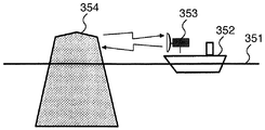
- the outline of the fifth embodiment will be described. From a ship 352 sailing on the sea 351, the visibility may be poor due to dense fog regardless of day or night, and the crew may not be able to identify the target object 354 such as drift ice. In such a case, by simultaneously measuring the distance and temperature of the target object 354 such as drift ice with the multi-function radar device 353, it is possible to identify that the target object 354 is drift ice, drifting material, high-temperature lava fragments, or the like.
- the ship 352 provided with the multi-function radar device 353 sails on the sea 351.
- the multi-function radar device 353 radiates a transmission signal from the transmission / reception antenna unit of the multi-function radar device 353 toward the target object 354.
- the radiated transmission signal is reflected by the target object 354, and the reflected wave is input to the transmission / reception antenna unit.
- the multi-function radar device 353 calculates the distance to the target object 354 based on the input reflected wave.
- the transmission / reception antenna unit receives a radiated wave from the target object 354 while the transmission signal is not being radiated or intermittently stopped.
- the multi-function radar device 353 calculates the temperature of the target object 354.
- the distance and the temperature may be calculated based on the above-described embodiment, or may be calculated based on a modification of the above-described embodiment. Further, by measuring the distance of the target object a plurality of times, the operation of the target object can also be known.
- a configuration for displaying the type of the identified object together with the measured distance and temperature may be provided.
- a pre-stored data table showing the relationship between the measured distance (motion) and temperature and the type of object is provided, and the multi-function radar device 352 further includes the distance (motion) of the target object 354.
- an object identification unit for identifying the type of the object may be provided based on the measured distance (operation) and the temperature of the object. If the type of the target object can be identified, the type of the object can be appropriately identified even by an operator who has little boarding experience or knowledge of the object.
- the fifth embodiment even if visibility is poor, by measuring the distance and temperature of a target object such as drift ice at the same time, it is possible to know in advance obstacles such as drift ice in the traveling direction of the ship or in any direction. be able to. In addition, the type of objects such as drift ice, drifting objects, and high-temperature lava fragments can be identified, contributing to the safe navigation of ships.
- the multi-function radar apparatus of this embodiment has an integrated antenna for measuring the distance and temperature, it is compared with a conventional radar apparatus in which the antenna for measuring the distance and temperature is separately attached. Thus, it is possible to measure the target object with high accuracy while minimizing the influence of ship sway.
- FIG. 12 is a sixth embodiment of a multi-function radar device to which the present invention is applied.
- the multi-function radar apparatus according to the present embodiment may be based on the first to fourth embodiments, or may be based on a modification of the embodiment.
- symbol is attached
- the outline of the sixth embodiment will be described.
- the target object 313 of the same color that moves from the background object 312 may not be discernible even if it is dark and foggy from the ice 311 day or night.
- the multi-function radar device 353 is installed on the ice 311.
- a transmission signal is radiated from the transmission / reception antenna unit of the multi-function radar device 353 toward the target object 313.
- the radiated transmission signal is reflected by the target object 313, and the reflected wave is input to the transmission / reception antenna unit.
- the multi-function radar device 353 calculates the distance to the target object 313 based on the input reflected wave.
- the transmitting / receiving antenna unit receives a radiated wave from the target object 313 while not transmitting a transmission signal or intermittently stopping. Based on the received radiation wave, the multi-function radar device 353 calculates the temperature of the target object 354.
- the distance and temperature may be calculated based on the above-described embodiment, or may be calculated based on a modification of the above-described embodiment. Further, by measuring the distance of the target object a plurality of times, the operation of the target object can also be known.
- the multi-function radar device 353 (in all the embodiments including the present embodiment) has a predetermined resolution, not only the target object 354 but also the information around the object target 354 according to the resolution. Can also be obtained. Further, by moving the position of the multi-function radar device 353 or moving the direction of the antenna, more information can be obtained, and for example, the distance and temperature of the background object 312 can be calculated. Thereby, the relative relationship between the background object 312 and the target object 313 can also be known.
- the multi-function radar device of the sixth embodiment by measuring simultaneously the distance and the temperature of the target object of the same color that moves with the object in the background, even if the field of view is dark and foggy and has poor visibility on ice, The method can identify the existence of objects that are difficult to judge.
- FIG. 13 shows a seventh embodiment of the multi-function radar device to which the present invention is applied.
- the multi-function radar apparatus according to the present embodiment may be based on the first to fourth embodiments, or may be based on a modification of the embodiment.
- symbol is attached
- the outline of the seventh embodiment will be described.
- the target object 323 When there is a target object 323 that moves in front of a fluid object 322 having a high emission luminance at a high temperature, such as a blast furnace 321, the target object 323 may not be identified.
- the multi-function radar device 353 by simultaneously measuring the distance and temperature of the moving target object with the multi-function radar device 353, it is possible to identify the presence of the target object 323 that is difficult to determine by an optical method.
- a multi-function radar device 353 is installed at an arbitrary location.
- the multi-function radar device 353 radiates a transmission signal from the transmission / reception antenna unit of the multi-function radar device 353 toward the target object 323.
- the radiated transmission signal is reflected by the target object 323, and the reflected wave is input to the transmission / reception antenna unit.
- the multi-function radar device 353 calculates the distance to the target object 323 based on the input reflected wave.
- the transmission / reception antenna unit receives the radiated wave from the target object 323 while the transmission signal is not being radiated or intermittently stopped. Based on the received radiation wave, the multi-function radar device 353 calculates the temperature of the target object 323.
- the distance and the temperature may be calculated based on the above-described embodiment, or may be calculated based on a modification of the above-described embodiment. Further, by measuring the distance of the target object a plurality of times, the operation of the target object can also be known.
- the multi-function radar device 353 uses electromagnetic waves in a frequency region different from that of visible light, the distance and temperature of the target object 323 can be calculated without being affected by visible light. Further, the distance and temperature of the blast furnace 321 and the flowing object 322 can be calculated by changing the position of the multi-function radar device 353 and the direction of the transmitting / receiving antenna unit. Thereby, the relative relationship among the target object 323, the blast furnace 321 and the fluidized object 322 can also be known.
- the multi-function radar device of the seventh embodiment when there is a target object that moves in front of a flowing object having high emission luminance at a high temperature such as a blast furnace, the distance and temperature of the moving target object are simultaneously measured. Accordingly, it is possible to identify the presence of a target object that is difficult to determine by an optical method.
- FIG. 14 is an eighth embodiment of a multi-function radar device to which the present invention is applied.
- the multi-function radar apparatus according to the present embodiment may be based on the first to fourth embodiments, or may be based on a modification of the embodiment.
- symbol is attached
- the outline of the eighth embodiment will be described.
- the target object 332 such as lava at the crater of the volcano 331 may not be identified due to poor visibility due to fog, smoke, water vapor or the like regardless of day or night.
- the multi-function radar device 353 is installed at an arbitrary position of the volcano 331, and the transmission / reception antenna unit of the multi-function radar device 353 is oriented in the direction in which the target object 332 is assumed to exist.
- the multi-function radar device 353 radiates a transmission signal toward the transmission / reception antenna unit 332.
- the radiated transmission signal is reflected by the target object 332, and the reflected wave is input to the transmission / reception antenna unit.
- the multi-function radar device 353 calculates the distance to the target object 313 based on the input reflected wave.
- the transmission / reception antenna unit receives a radiated wave from the target object 332 while not transmitting a transmission signal or intermittently stopping. Based on the received radiation wave, the multi-function radar device 353 calculates the temperature of the target object 332.
- the distance and the temperature may be calculated based on the above-described embodiment, or may be calculated based on a modification of the above-described embodiment. Further, by measuring the distance of the target object a plurality of times, the operation of the target object can also be known.
- the multi-function radar device 353 can confirm the presence / absence of the target 332 from the calculated distance and temperature. If it is determined that the target object 332 does not exist, the transmission signal is radiated again by moving the position of the multi-function radar device 353 or changing the direction of the transmission / reception antenna unit.
- the time for one time for calculating the distance to the target object and the temperature is short. If the above processing is performed while oscillating the antenna, first, an entire area having a predetermined size including a place where the target object 332 is supposed to exist can be easily searched. Therefore, a method may be used in which an approximate guideline is set and then the antenna is directed to a point where the target object 332 is supposed to exist and the details are searched.
- the multi-function radar device 353 can radiate radio waves to the target object 332 while avoiding the influence of fog, smoke, water vapor, etc. that block the view, and receives reflected waves and radiated waves from the target object. Therefore, the distance and temperature of the target object 323 can be calculated.
- the multi-function radar device of the eighth embodiment by simultaneously measuring the distance and temperature of a target object such as lava in a crater of a volcano even if visibility is poor due to fog, smoke, water vapor, etc., day or night Therefore, it is possible to identify the presence of an object that is difficult to judge by an optical method.
- a target object such as lava in a crater of a volcano even if visibility is poor due to fog, smoke, water vapor, etc., day or night Therefore, it is possible to identify the presence of an object that is difficult to judge by an optical method.
- FIG. 15 shows a ninth embodiment of a multi-function radar device to which the present invention is applied.
- the multi-function radar apparatus according to the present embodiment may be based on the first to fourth embodiments, or may be based on a modification of the embodiment.
- symbol is attached
- the outline of the ninth embodiment will be described.
- the target object 342 such as a living thing which is poor in visibility due to fog, smoke or the like regardless of day or night, or is hidden behind the plant 341 or goes out, cannot be identified.
- the target object 342 can be identified separately from the plant 341 that moves due to wind and rain.
- the multi-function radar device is installed at an arbitrary position.
- a transmission signal is radiated from the transmission / reception antenna unit of the multi-function radar device 353 toward the target object 342.
- the radiated transmission signal is reflected by the target object 342, and the reflected wave is input to the transmission / reception antenna unit.
- the multi-function radar device 353 calculates the distance to the target object 313 based on the input reflected wave.
- the transmission / reception antenna unit receives a radiated wave from the target object 342 while not transmitting a transmission signal or intermittently stopping. Based on the received radiation wave, the multi-function radar device 353 calculates the temperature of the target object 354.
- the distance and temperature may be calculated based on the above-described embodiment, or may be calculated based on a modification of the above-described embodiment. Further, by measuring the distance of the target object a plurality of times, the operation of the target object can also be known.
- the multifunction radar apparatus 353 knows the distance and temperature of the target object 342, the organism 342 and the surrounding plant 341, by moving the position of the multifunction radar apparatus 353 and / or moving the antenna unit. You can also.
- the target object 342 such as a living thing and the plant 341 are clearly different in movement and temperature.
- Organism temperatures are relatively high and plant temperatures are relatively low. Taking these into consideration, the organism 342 and the plant 341 can be separated and identified.
- the distance between the target object such as a living thing that is hidden behind a plant or appears outside, even if the visibility is poor due to fog, smoke, etc.
- the temperature at the same time it can be distinguished from plants that move by wind and rain.
- the multi-function radar device of the present invention is a high-frequency signal generating means for outputting a frequency-modulated transmission signal, radiates the transmission signal to a target object, and receives measurement information about the target object as a received signal.
- a multi-function radar comprising: an antenna for performing the measurement; a frequency conversion unit that generates a beat signal by mixing the transmission signal and the reception signal; and a signal processing unit that performs measurement on the target object based on the beat signal
- An apparatus comprising transmission signal intermittent stop means for intermittently radiating the transmission signal, wherein the antenna receives a reflected wave from the target object as the measurement information while radiating the transmission signal, While the transmission signal is not radiated, a radiated wave from the target object is received as the measurement information, and the signal processing means releases the transmission signal.
- the distance to the target object is measured based on the beat signal while the temperature of the target object is measured based on the beat signal while the transmission signal is not radiated. .
- the gain adjustment means may adjust the gain of the said received signal.
- the gain adjusting means outputs a reception signal input while the transmission signal is radiated with a low gain, and outputs a reception signal input while the transmission signal is not radiated with a high gain. May be.
- a measurement noise switching unit that inputs thermal noise inside the multi-function radar device as the reception signal is provided, and the signal processing unit detects a radiated wave from the target object while the transmission signal is not radiated.
- the beat signal based on the beat signal based on the thermal noise inside the multi-function radar device may be compared to measure the temperature of the target object.
Landscapes
- Engineering & Computer Science (AREA)
- Radar, Positioning & Navigation (AREA)
- Remote Sensing (AREA)
- Physics & Mathematics (AREA)
- Computer Networks & Wireless Communication (AREA)
- General Physics & Mathematics (AREA)
- Ocean & Marine Engineering (AREA)
- Electromagnetism (AREA)
- Radar Systems Or Details Thereof (AREA)
- Radiation Pyrometers (AREA)
Abstract
Description
また、温度を持つすべての物体は赤外線を自然に放射しており、高い温度の物体ほど強く赤外線を放射する。このことより、目標物体から放射される赤外線を受信して、受信した赤外線の強度を解析することで、目標物体の温度を測定する赤外線温度計等が知られている。
図1に示す複合機能レーダ装置は、信号処理部6と周波数変調信号発生部8と高周波信号発生部9と高周波信号分岐部10と間欠停止信号発生部7と送信間欠停止スイッチ11と送信信号増幅部12とサーキュレータ部2と送受信アンテナ部1と受信信号増幅部3と周波数変換部4とビート信号増幅部5とを備える。
送信間欠停止スイッチ11には、信号処理部6の制御による間欠停止信号発生部7からの制御電圧が入力される。送信間欠停止スイッチ11は、間欠停止信号発生部7から出力される制御電圧に応じて、高周波信号分岐部10から出力される送信信号を送信信号増幅部12に出力し、又は出力しないように、信号経路を切り替える。
本実施形態は、第1の実施形態における受信信号増幅部3の代わりに、利得調整部300を設けたものである。第1の実施形態と同一の機能を有する構成部品には同一の符号を付し、説明を省略する。
本実施形態は、第1の実施形態におけるサーキュレータ部2と受信信号増幅部3との間に測定雑音切替部200を設けたものである。第1の実施形態と同一の機能を有する構成部品には同一の符号を付し、説明を省略する。
本実施形態は、上述した第2の実施形態と第3の実施形態とを第1の実施形態に組み合わせたものである。即ち、本実施形態は、上述した測定雑音切替部200と利得調整部300とを備えている。第1の実施形態と同一の機能を有する構成部品には同一の符号を付し、説明を省略する。
図11は、本発明の第5の実施形態を示す。本実施例の複合機能レーダ装置は、第1から第4の実施形態に基づいてもよく、当該実施形態に改変を加えたものに基づいてもよい。なお、他の実施形態と同一の機能を有する構成部品には同一の符号を付し、説明を省略する。
図12は、本発明を適用した複合機能レーダ装置の第6の実施形態である。本実施例の複合機能レーダ装置は、第1から第4の実施形態に基づいてもよく、当該実施形態に改変を加えたものに基づいてもよい。なお、他の実施形態と同一の機能を有する構成部品には同一の符号を付し、説明を省略する。
図13は、本発明を適用した複合機能レーダ装置の第7の実施形態である。本実施例の複合機能レーダ装置は、第1から第4の実施形態に基づいてもよく、当該実施形態に改変を加えたものに基づいてもよい。なお、他の実施形態と同一の機能を有する構成部品には同一の符号を付し、説明を省略する。
図14は、本発明を適用した複合機能レーダ装置の第8の実施形態である。本実施例の複合機能レーダ装置は、第1から第4の実施形態に基づいてもよく、当該実施形態に改変を加えたものに基づいてもよい。なお、他の実施形態と同一の機能を有する構成部品には同一の符号を付し、説明を省略する。
図15は、本発明を適用した複合機能レーダ装置の第9の実施形態である。本実施例の複合機能レーダ装置は、第1から第4の実施形態に基づいてもよく、当該実施形態に改変を加えたものに基づいてもよい。なお、他の実施形態と同一の機能を有する構成部品には同一の符号を付し、説明を省略する。
また、前記利得調整手段は、前記送信信号が放射されている間に入力される受信信号を低い利得で出力し、前記送信信号が放射されていない間に入力される受信信号を高い利得で出力してもよい。
また、前記複合機能レーダ装置の内部の熱雑音を前記受信信号として入力する測定雑音切換手段を備え、前記信号処理部は、前記送信信号が放射されていない間、前記目標物体からの輻射波に基づくビート信号と前記複合機能レーダ装置の内部の熱雑音に基づくビート信号とを比較して、前記目標物体の温度を測定してもよい。
2、902 サーキュレータ部
3、903 受信信号増幅部
4、904 周波数変換部
5、905 ビート信号増幅部
6、60、906 信号処理部
7 間欠停止信号発生部
8、908 周波数変調信号発生部
9、909 高周波信号発生部
10、910 高周波信号分岐部
11 送信間欠停止スイッチ
12、912 送信信号増幅部
13、913 目標物体
200 測定雑音切替部
201 受信信号切替スイッチ
202 測定雑音切替信号発生部
300 利得調整部
301 第1受信信号切替スイッチ
302 第1受信信号増幅部
303 第2受信信号増幅部
304 第2受信信号切替スイッチ
305 利得切替信号発生部
351 海上
352 船舶
353 複合機能レーダ装置
354 目標物体
311 氷上
312 物体
313 目標物体
321 溶鉱炉
322 流動物体
323 目標物体
331 火山
332 目標物体
342 目標物体
341 植物
914 赤外線受光レンズ部
915 赤外線温度計部
Claims (7)
- 周波数変調された送信信号を出力する高周波信号発生手段と、前記送信信号を目標物体に放射すると共に、前記目標物体に関する測定情報を受信信号として受信するアンテナと、前記送信信号と前記受信信号とを混合してビート信号を生成する周波数変換手段と、前記ビート信号に基づいて前記目標物体に関する測定を行う信号処理手段と、を備えた複合機能レーダ装置であって、
前記送信信号の放射を間欠させる送信信号間欠停止手段を備え、
前記アンテナは、前記送信信号を放射している間、前記目標物体からの反射波を前記測定情報として受信し、前記送信信号を放射していない間、前記目標物体からの輻射波を前記測定情報として受信し、
前記信号処理手段は、前記送信信号が放射されている間、前記ビート信号に基づいて前記目標物体までの距離を測定し、前記送信信号が放射されていない間、前記ビート信号に基づいて前記目標物体の温度を測定する
ことを特徴とする複合機能レーダ装置。 - 請求項1記載の複合機能レーダ装置であって、
前記アンテナと前記周波数変換手段との間に受信信号増幅手段を更に備え、
前記受信信号増幅手段は、前記受信信号を異なる利得で増幅できるように構成されており、
前記輻射波を前記測定情報として受信しているときは、前記受信信号増幅手段の利得を相対的に高く調整し、
前記反射波を前記測定情報として受信しているときは、前記受信信号増幅手段の利得を相対的に低く調整する
ことを特徴とする複合機能レーダ装置。 - 請求項1または請求項2に記載の複合機能レーダ装置であって、更に、
前記受信信号の入力を間欠させて、前記受信信号を受信していないときは、前記複合機能レーダ内部の熱雑音を入力する熱雑音切替手段を備え、
複合機能レーダ装置内部の前記熱雑音に基づくビート信号と、前記輻射波に基づくビート信号とを比較し、前記目標物体の温度を測定する
ことを特徴とする複合機能レーダ装置。 - 請求項1から請求項3までのいずれか1つに記載の複合機能レーダ装置であって、更に、
前記複合機能レーダ内部の熱雑音を前記周波数変換手段へ入力する熱雑音切替手段を備え、
複合機能レーダ装置内部の前記熱雑音に基づくビート信号と、前記反射波に基づくビート信号とを比較し、前記目標物体までの距離を測定する
ことを特徴とする複合機能レーダ装置。 - 請求項3または4記載の複合機能レーダ装置であって、
前記送信信号間欠停止手段は、第1の間欠周期で前記送信信号の放射を間欠させ、
熱雑音切替手段は、第1の間欠周期の信号が所定の条件下にあるとき、第2の間欠周期で前記受信信号の入力を間欠させ、
前記第2の間欠周期は、前記第1の間欠周期よりも短い
ことを特徴とする複合機能レーダ装置。 - 複合機能レーダ装置における複数の物理量を測定する方法であって、
周波数変調された送信信号を出力するステップと、
前記送信信号を目標物体に放射すると共に、前記目標物体に関する測定情報を受信信号として受信するステップと、
前記送信信号と前記受信信号とを混合してビート信号を生成する周波数変換をするステップと、
前記送信信号の放射を間欠させるステップと、
前記送信信号を放射している間、前記目標物体からの反射波を前記測定情報として受信するステップと、
前記送信信号を放射していない間、前記目標物体からの輻射波を前記測定情報として受信するステップと、
前記送信信号が放射されている間、前記ビート信号に基づいて前記目標物体までの距離を測定するステップと、
前記送信信号が放射されていない間、前記ビート信号に基づいて前記目標物体の温度を測定するステップと、
を備えることを特徴とする方法。 - 周波数変調された送信信号を出力する高周波信号発生手段と、前記送信信号を目標物体に放射すると共に、前記目標物体に関する測定情報を受信信号として受信するアンテナと、前記送信信号と前記受信信号とを混合してビート信号を生成する周波数変換手段と、前記ビート信号に基づいて前記目標物体に関する測定を行う信号処理手段と、を備えた複合機能レーダ装置のプログラムであって、
前記送信信号の放射を間欠させるステップと、
前記送信信号を放射している間、前記目標物体からの反射波を前記測定情報として受信し、前記送信信号を放射していない間、前記目標物体からの輻射波を前記測定情報として受信するステップと、
前記送信信号が放射されている間、前記ビート信号に基づいて前記目標物体までの距離を測定し、前記送信信号が放射されていない間、前記ビート信号に基づいて前記目標物体の温度を測定するステップと、
備えることを特徴とする複合機能レーダ装置のプログラム。
Priority Applications (2)
| Application Number | Priority Date | Filing Date | Title |
|---|---|---|---|
| CN2010800086799A CN102334043A (zh) | 2009-03-05 | 2010-01-25 | 复合功能雷达装置 |
| US13/254,065 US8537049B2 (en) | 2009-03-05 | 2010-01-25 | Multi-function radar device |
Applications Claiming Priority (2)
| Application Number | Priority Date | Filing Date | Title |
|---|---|---|---|
| JP2009051838A JP2010204003A (ja) | 2009-03-05 | 2009-03-05 | 複合機能レーダ装置 |
| JP2009-051838 | 2009-03-05 |
Publications (1)
| Publication Number | Publication Date |
|---|---|
| WO2010100976A1 true WO2010100976A1 (ja) | 2010-09-10 |
Family
ID=42709539
Family Applications (1)
| Application Number | Title | Priority Date | Filing Date |
|---|---|---|---|
| PCT/JP2010/050888 Ceased WO2010100976A1 (ja) | 2009-03-05 | 2010-01-25 | 複合機能レーダ装置 |
Country Status (4)
| Country | Link |
|---|---|
| US (1) | US8537049B2 (ja) |
| JP (1) | JP2010204003A (ja) |
| CN (1) | CN102334043A (ja) |
| WO (1) | WO2010100976A1 (ja) |
Cited By (1)
| Publication number | Priority date | Publication date | Assignee | Title |
|---|---|---|---|---|
| CN110579758A (zh) * | 2018-06-07 | 2019-12-17 | 立积电子股份有限公司 | 移动物体侦测电路及移动物体侦测方法 |
Families Citing this family (9)
| Publication number | Priority date | Publication date | Assignee | Title |
|---|---|---|---|---|
| JP2010204003A (ja) * | 2009-03-05 | 2010-09-16 | Hitachi Kokusai Electric Inc | 複合機能レーダ装置 |
| JP5522733B2 (ja) * | 2010-09-30 | 2014-06-18 | 株式会社ヨコオ | ベースバンド増幅ユニット及びパルスレーダ装置 |
| US20140095600A1 (en) * | 2012-09-28 | 2014-04-03 | Bradford H. Needham | Multiple-device screen capture |
| US9354306B1 (en) | 2013-05-10 | 2016-05-31 | Rockwell Collins, Inc. | Single antenna altimeter system and related method |
| JP6272703B2 (ja) * | 2014-01-30 | 2018-01-31 | パナソニック株式会社 | レーダ装置 |
| KR102417610B1 (ko) * | 2016-03-03 | 2022-07-07 | 삼성전자주식회사 | 근거리 초고주파 레이더를 이용한 코드 판독 방법 및 장치 |
| US10578708B2 (en) * | 2016-04-08 | 2020-03-03 | Raytheon Company | Switchable transmit/receive (T/R) module |
| JP6717254B2 (ja) * | 2017-04-19 | 2020-07-01 | 株式会社デンソー | レーダ信号処理器及びレーダシステム |
| WO2019035348A1 (ja) * | 2017-08-18 | 2019-02-21 | 古野電気株式会社 | レーダ装置及びレーダ装置の受信利得変更方法 |
Citations (5)
| Publication number | Priority date | Publication date | Assignee | Title |
|---|---|---|---|---|
| JPS6154479A (ja) * | 1984-08-24 | 1986-03-18 | Tech Res & Dev Inst Of Japan Def Agency | 目標追尾方式 |
| JPS6219780A (ja) * | 1985-07-19 | 1987-01-28 | Tech Res & Dev Inst Of Japan Def Agency | 複合目標検知方式 |
| JPS63122979A (ja) * | 1986-11-12 | 1988-05-26 | Tech Res & Dev Inst Of Japan Def Agency | ミリ波レ−ダ装置 |
| JPH05240947A (ja) * | 1992-02-27 | 1993-09-21 | Honda Motor Co Ltd | Fmレーダ装置 |
| JP2006038798A (ja) * | 2004-07-30 | 2006-02-09 | Ihi Aerospace Co Ltd | 発熱物体の位置検出装置 |
Family Cites Families (11)
| Publication number | Priority date | Publication date | Assignee | Title |
|---|---|---|---|---|
| JPH07209413A (ja) | 1994-01-20 | 1995-08-11 | Kokusai Electric Co Ltd | サーボスロープ式fm−cw形レーダ |
| GB2291551B (en) * | 1994-06-24 | 1998-03-18 | Roscoe C Williams Limited | Electronic viewing aid |
| US5677695A (en) * | 1994-11-21 | 1997-10-14 | Fujitsu Limited | Radar apparatus for detecting a distance/velocity |
| JP2003028951A (ja) | 2001-07-11 | 2003-01-29 | Fujitsu Ten Ltd | レーダ装置 |
| JP2003172776A (ja) * | 2001-12-10 | 2003-06-20 | Fujitsu Ten Ltd | レーダ装置 |
| JP4190335B2 (ja) * | 2003-04-03 | 2008-12-03 | 富士通テン株式会社 | レーダ装置及びその信号処理方法 |
| WO2007083479A1 (ja) * | 2006-01-23 | 2007-07-26 | Murata Manufacturing Co., Ltd. | レーダ装置 |
| EP2045616B1 (en) * | 2006-07-21 | 2013-09-11 | Mitsubishi Electric Corporation | Modulation signal generation circuit, transmission/reception module, and radar device |
| JP4871104B2 (ja) * | 2006-11-24 | 2012-02-08 | 日立オートモティブシステムズ株式会社 | レーダ装置及び信号処理方法 |
| JP2010204003A (ja) * | 2009-03-05 | 2010-09-16 | Hitachi Kokusai Electric Inc | 複合機能レーダ装置 |
| JP5693906B2 (ja) * | 2010-10-13 | 2015-04-01 | 三菱電機株式会社 | レーダ装置 |
-
2009
- 2009-03-05 JP JP2009051838A patent/JP2010204003A/ja active Pending
-
2010
- 2010-01-25 WO PCT/JP2010/050888 patent/WO2010100976A1/ja not_active Ceased
- 2010-01-25 US US13/254,065 patent/US8537049B2/en not_active Expired - Fee Related
- 2010-01-25 CN CN2010800086799A patent/CN102334043A/zh active Pending
Patent Citations (5)
| Publication number | Priority date | Publication date | Assignee | Title |
|---|---|---|---|---|
| JPS6154479A (ja) * | 1984-08-24 | 1986-03-18 | Tech Res & Dev Inst Of Japan Def Agency | 目標追尾方式 |
| JPS6219780A (ja) * | 1985-07-19 | 1987-01-28 | Tech Res & Dev Inst Of Japan Def Agency | 複合目標検知方式 |
| JPS63122979A (ja) * | 1986-11-12 | 1988-05-26 | Tech Res & Dev Inst Of Japan Def Agency | ミリ波レ−ダ装置 |
| JPH05240947A (ja) * | 1992-02-27 | 1993-09-21 | Honda Motor Co Ltd | Fmレーダ装置 |
| JP2006038798A (ja) * | 2004-07-30 | 2006-02-09 | Ihi Aerospace Co Ltd | 発熱物体の位置検出装置 |
Cited By (2)
| Publication number | Priority date | Publication date | Assignee | Title |
|---|---|---|---|---|
| CN110579758A (zh) * | 2018-06-07 | 2019-12-17 | 立积电子股份有限公司 | 移动物体侦测电路及移动物体侦测方法 |
| CN110579758B (zh) * | 2018-06-07 | 2023-07-21 | 立积电子股份有限公司 | 移动物体侦测电路及移动物体侦测方法 |
Also Published As
| Publication number | Publication date |
|---|---|
| US8537049B2 (en) | 2013-09-17 |
| JP2010204003A (ja) | 2010-09-16 |
| US20120026030A1 (en) | 2012-02-02 |
| CN102334043A (zh) | 2012-01-25 |
Similar Documents
| Publication | Publication Date | Title |
|---|---|---|
| WO2010100976A1 (ja) | 複合機能レーダ装置 | |
| US8791852B2 (en) | Standoff range sense through obstruction radar system | |
| KR101971684B1 (ko) | 레이저 피아식별 시스템 및 방법 | |
| JP6429723B2 (ja) | レーザレーダ装置及び観測方法 | |
| JP5621499B2 (ja) | パルスレーダ装置 | |
| CA2982490A1 (en) | Road information detection apparatus and road information detection method | |
| US20190265359A1 (en) | System and Method for Improving the Resolution and Sensitivity of Lidar | |
| JP2014006072A (ja) | レーダ装置、目標データ取得方法及び、目標追尾システム | |
| JP5503141B2 (ja) | 目標検出装置 | |
| KR100794533B1 (ko) | 표적의 추적을 위한, 자기유도 방법 및 장치 | |
| KR101743348B1 (ko) | 실내 측위 시스템 및 방법 | |
| CN103983962A (zh) | 一种相位测量的校准方法、装置及测量装置 | |
| JP4266810B2 (ja) | 風速ベクトル算出装置 | |
| KR101012161B1 (ko) | 디지털 레이더의 안테나 패턴을 측정하기 위한 시스템 및 방법 | |
| CN102403575A (zh) | 重构光子tr信标的方法和装置 | |
| KR102723999B1 (ko) | 능동 센서 시스템을 교정하기 위한 방법 | |
| JP2018155658A (ja) | 物体検出装置、物体検出方法、および物体検出プログラム | |
| KR101807774B1 (ko) | 트랩 코일을 사용하여 송신 안테나를 구현한 도플러 센서 | |
| JP2009244194A (ja) | レーダ装置 | |
| JP5405882B2 (ja) | 無線センサ装置 | |
| JP2010133868A (ja) | 目標検出装置 | |
| KR20180097022A (ko) | 하이브리드 마이크로파 영상 시스템 및 이의 동작 방법 | |
| JP2019049415A (ja) | アクティブリフレクタおよび合成開口レーダシステム | |
| JP2001208828A (ja) | レーダ装置 | |
| RU2226701C2 (ru) | Способ определения координат объектов и радиолокационная станция для его реализации |
Legal Events
| Date | Code | Title | Description |
|---|---|---|---|
| WWE | Wipo information: entry into national phase |
Ref document number: 201080008679.9 Country of ref document: CN |
|
| 121 | Ep: the epo has been informed by wipo that ep was designated in this application |
Ref document number: 10748573 Country of ref document: EP Kind code of ref document: A1 |
|
| WWE | Wipo information: entry into national phase |
Ref document number: 13254065 Country of ref document: US |
|
| NENP | Non-entry into the national phase |
Ref country code: DE |
|
| 122 | Ep: pct application non-entry in european phase |
Ref document number: 10748573 Country of ref document: EP Kind code of ref document: A1 |