WO2010100834A1 - 搬送システム - Google Patents
搬送システム Download PDFInfo
- Publication number
- WO2010100834A1 WO2010100834A1 PCT/JP2010/000900 JP2010000900W WO2010100834A1 WO 2010100834 A1 WO2010100834 A1 WO 2010100834A1 JP 2010000900 W JP2010000900 W JP 2010000900W WO 2010100834 A1 WO2010100834 A1 WO 2010100834A1
- Authority
- WO
- WIPO (PCT)
- Prior art keywords
- transport vehicle
- data
- stop position
- stop
- transport
- Prior art date
- Legal status (The legal status is an assumption and is not a legal conclusion. Google has not performed a legal analysis and makes no representation as to the accuracy of the status listed.)
- Ceased
Links
Images


Classifications
-
- H—ELECTRICITY
- H10—SEMICONDUCTOR DEVICES; ELECTRIC SOLID-STATE DEVICES NOT OTHERWISE PROVIDED FOR
- H10P—GENERIC PROCESSES OR APPARATUS FOR THE MANUFACTURE OR TREATMENT OF DEVICES COVERED BY CLASS H10
- H10P72/00—Handling or holding of wafers, substrates or devices during manufacture or treatment thereof
- H10P72/30—Handling or holding of wafers, substrates or devices during manufacture or treatment thereof for conveying, e.g. between different workstations
- H10P72/32—Handling or holding of wafers, substrates or devices during manufacture or treatment thereof for conveying, e.g. between different workstations between different workstations
- H10P72/3218—Conveying cassettes, containers or carriers
-
- H—ELECTRICITY
- H10—SEMICONDUCTOR DEVICES; ELECTRIC SOLID-STATE DEVICES NOT OTHERWISE PROVIDED FOR
- H10P—GENERIC PROCESSES OR APPARATUS FOR THE MANUFACTURE OR TREATMENT OF DEVICES COVERED BY CLASS H10
- H10P72/00—Handling or holding of wafers, substrates or devices during manufacture or treatment thereof
- H10P72/30—Handling or holding of wafers, substrates or devices during manufacture or treatment thereof for conveying, e.g. between different workstations
- H10P72/34—Handling or holding of wafers, substrates or devices during manufacture or treatment thereof for conveying, e.g. between different workstations the wafers being stored in a carrier, involving loading and unloading
- H10P72/3404—Storage means
-
- B—PERFORMING OPERATIONS; TRANSPORTING
- B65—CONVEYING; PACKING; STORING; HANDLING THIN OR FILAMENTARY MATERIAL
- B65G—TRANSPORT OR STORAGE DEVICES, e.g. CONVEYORS FOR LOADING OR TIPPING, SHOP CONVEYOR SYSTEMS OR PNEUMATIC TUBE CONVEYORS
- B65G1/00—Storing articles, individually or in orderly arrangement, in warehouses or magazines
- B65G1/02—Storage devices
- B65G1/04—Storage devices mechanical
- B65G1/0457—Storage devices mechanical with suspended load carriers
-
- H—ELECTRICITY
- H10—SEMICONDUCTOR DEVICES; ELECTRIC SOLID-STATE DEVICES NOT OTHERWISE PROVIDED FOR
- H10P—GENERIC PROCESSES OR APPARATUS FOR THE MANUFACTURE OR TREATMENT OF DEVICES COVERED BY CLASS H10
- H10P72/00—Handling or holding of wafers, substrates or devices during manufacture or treatment thereof
- H10P72/30—Handling or holding of wafers, substrates or devices during manufacture or treatment thereof for conveying, e.g. between different workstations
- H10P72/32—Handling or holding of wafers, substrates or devices during manufacture or treatment thereof for conveying, e.g. between different workstations between different workstations
- H10P72/3221—Overhead conveying
-
- H—ELECTRICITY
- H10—SEMICONDUCTOR DEVICES; ELECTRIC SOLID-STATE DEVICES NOT OTHERWISE PROVIDED FOR
- H10P—GENERIC PROCESSES OR APPARATUS FOR THE MANUFACTURE OR TREATMENT OF DEVICES COVERED BY CLASS H10
- H10P72/00—Handling or holding of wafers, substrates or devices during manufacture or treatment thereof
- H10P72/30—Handling or holding of wafers, substrates or devices during manufacture or treatment thereof for conveying, e.g. between different workstations
- H10P72/32—Handling or holding of wafers, substrates or devices during manufacture or treatment thereof for conveying, e.g. between different workstations between different workstations
- H10P72/3222—Loading to or unloading from a conveyor
-
- H—ELECTRICITY
- H10—SEMICONDUCTOR DEVICES; ELECTRIC SOLID-STATE DEVICES NOT OTHERWISE PROVIDED FOR
- H10P—GENERIC PROCESSES OR APPARATUS FOR THE MANUFACTURE OR TREATMENT OF DEVICES COVERED BY CLASS H10
- H10P72/00—Handling or holding of wafers, substrates or devices during manufacture or treatment thereof
- H10P72/30—Handling or holding of wafers, substrates or devices during manufacture or treatment thereof for conveying, e.g. between different workstations
- H10P72/34—Handling or holding of wafers, substrates or devices during manufacture or treatment thereof for conveying, e.g. between different workstations the wafers being stored in a carrier, involving loading and unloading
- H10P72/3402—Mechanical parts of transfer devices
-
- B—PERFORMING OPERATIONS; TRANSPORTING
- B65—CONVEYING; PACKING; STORING; HANDLING THIN OR FILAMENTARY MATERIAL
- B65G—TRANSPORT OR STORAGE DEVICES, e.g. CONVEYORS FOR LOADING OR TIPPING, SHOP CONVEYOR SYSTEMS OR PNEUMATIC TUBE CONVEYORS
- B65G2201/00—Indexing codes relating to handling devices, e.g. conveyors, characterised by the type of product or load being conveyed or handled
- B65G2201/02—Articles
- B65G2201/0297—Wafer cassette
Definitions
- the present invention relates to a transport system that controls a transport vehicle that transports articles.
- transport system that is a system for transporting articles using a transport vehicle such as a ceiling transport vehicle.
- each manufacturing process is divided into areas called bays, and each bay is provided with a peripheral circuit for circulating a plurality of overhead transport vehicles in one direction.
- each of the plurality of transport vehicles transports an article such as a wafer, which is a material of the semiconductor element, to a manufacturing apparatus in the bay. Therefore, the transport vehicle stops at a predetermined position.
- Patent Document 1 discloses a technique regarding control for stopping an overhead traveling vehicle (conveyance vehicle) at a stop position.
- a manufacturing apparatus installed in a factory may be provided with a detachable apparatus (hereinafter referred to as a detachable apparatus).
- the transport vehicle may transport the article to a position where the manufacturing device supplies the manufactured product, for example.
- the stop position of the transport vehicle changes depending on whether or not the removable device is attached to the manufacturing apparatus, the operator needs to adjust stop position data indicating the stop position of the transport vehicle.
- This adjustment work must be performed manually by the operator, and the period during which the adjustment work is performed (hereinafter referred to as the adjustment period) is very long (for example, 1 hour). For this reason, in the adjustment period and the area where the manufacturing apparatus is installed, the transport vehicle cannot be moved, and the adjustment period ends, and there is a long time until the transport vehicle is restarted. As a result, there is a problem that it takes a long time to switch the stop position of the transport vehicle.
- the present invention has been made to solve the above-described problems, and an object of the present invention is to provide a transport system that can quickly switch the stop position of the transport vehicle.
- a transport system includes a predetermined travel path, a transport vehicle capable of transporting articles to the first device by traveling on the travel path, And a controller for controlling the transport vehicle.
- the transport system further includes a second device that is detachable from the first device and on which the transport vehicle can place an article.
- the controller stops the first data for stopping at the first stop position at which the transport vehicle can place articles on the second device or the second stop position corresponding to the first device.
- the transmission part which transmits the 2nd data for this to a conveyance vehicle is provided.
- the transport vehicle performs a control to stop the transport vehicle at the first stop position when the first data is received with the communication unit that receives the first data or the second data, and when the second data is received, the transport vehicle And a stop control unit that performs control for stopping at a second stop position.
- the stop control unit performs control to stop the transport vehicle at the first stop position when the first data is received, and performs control to stop the transport vehicle at the second stop position when the second data is received. . That is, the stop position of the transport vehicle can be quickly switched according to the type of received data. Therefore, the stop position of the transport vehicle can be quickly switched.
- this invention can also be implement
- the present invention can also be implemented as a control program that causes a controller, which is a control device, to execute each of these steps.
- the present invention can quickly switch the stop position of the transport vehicle.
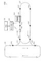
- FIG. 1 is a diagram showing a configuration of a transport system in the present embodiment.
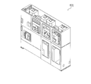
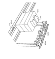
- FIG. 2 is a perspective view showing an external appearance of the buffer device.
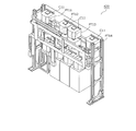
- FIG. 3 is a perspective view showing the inside of the buffer device.
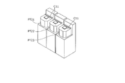
- FIG. 4 is a diagram illustrating a plurality of load ports when the buffer device is detached from the manufacturing apparatus.
- FIG. 5 is a perspective view showing the appearance of the transport vehicle.
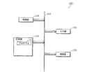
- FIG. 6 is a block diagram showing a hardware configuration in the ground controller.
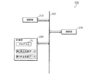
- FIG. 7 is a block diagram illustrating a hardware configuration in the transport vehicle.
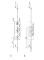
- FIG. 8 is a diagram for explaining a stop position of the transport vehicle.
- FIG. 9 is a diagram illustrating first stop position data as an example.
- FIG. 10 is a diagram illustrating second stop position data as an example.
- FIG. 9 is a diagram illustrating first stop position data as an example.
- FIG. 11 is a diagram illustrating processing performed in each of the MES, the ground controller, the transport vehicle, the buffer device, and the manufacturing device when the buffer device is removed from the manufacturing device.
- FIG. 12 is a diagram illustrating processing performed in each of the MES, the ground controller, the transport vehicle, the buffer device, and the manufacturing device when the buffer device is attached to the manufacturing device.
- FIG. 13 is a block diagram showing a characteristic functional configuration of the transport system according to the present invention.
- FIG. 1 is a diagram illustrating a configuration of a transport system 1000 according to the present embodiment. 1 shows a MES (Manufacturing Execution System) 50 that is not included in the transport system 1000 for convenience of explanation.
- MES Manufacturing Execution System
- the transport system 1000 is provided in a facility such as a factory for manufacturing semiconductor elements, for example.
- the transport system 1000 includes a ground controller 100, a travel path L ⁇ b> 10, a connection path L ⁇ b> 20, connection paths L ⁇ b> 31 and L ⁇ b> 32, a transport vehicle 200, a manufacturing apparatus 410, and a buffer apparatus 420. Including.
- the travel path L10 and the connection paths L20, L31, and L32 are travel paths for the transport vehicle 200 to travel.
- the travel path L10 and the connection paths L20, L31, and L32 are arranged on the ceiling of the facility.
- the travel path L10 is a travel path that passes through points P11 to P16.
- Each of the traveling path L10 and the connecting path L20 is configured such that the transport vehicle 200 can travel only clockwise, for example.
- the connection paths L31 and L32 are travel paths that connect the travel path L10 and the connection path L20.
- the MES 50 is a computer for controlling the ground controller 100.
- the MES 50 manages the status of each device in the transport system 1000 by communicating with the ground controller 100.
- the ground controller 100 is a computer having a function of controlling the transport vehicle 200.
- the transport vehicle 200 is an overhead transport vehicle that moves along the travel path L10 and the like.
- the manufacturing apparatus 410 is an apparatus that generates, for example, a wafer that is a material of a semiconductor element.
- the buffer device 420 is a device having a plurality of load ports on which cassettes can be placed.
- a cassette is a container in which a predetermined number of wafers generated by the manufacturing apparatus 410 can be placed.
- the buffer device 420 is a device that can be attached to and detached from the manufacturing device 410. That is, the buffer device 420 is a device that can be moved manually by an operator. Note that the buffer device 420 includes a computer capable of performing various processes.
- ground controller 100 communicates with the buffer device 420.
- FIG. 2 is a perspective view showing an external appearance of the buffer device 420.
- FIG. 3 is a perspective view showing the inside of the buffer device 420.
- the buffer device 420 has a plurality of load ports on which the cassette C11 can be placed. Some of the plurality of load ports are, for example, load ports PT11, PT12, PT13, and PT14.
- FIG. 4 is a diagram showing a plurality of load ports when the buffer device 420 is detached from the manufacturing device 410.
- the load ports PT21, PT22, and PT23 shown in FIG. 4 are arranged at positions where the wafer manufactured by the manufacturing apparatus 410 can be received from the manufacturing apparatus 410.
- the positions of the load ports PT21, PT22, PT23 are fixed. That is, each position of the load ports PT21, PT22, PT23 is a position associated with the manufacturing apparatus 410. That is, each of the load ports PT21, PT22, PT23 is a load port associated with the manufacturing apparatus 410.
- a cassette C11 can be placed on each of the load ports PT21, PT22, PT23.
- the manufacturing apparatus 410 carries out the manufactured wafer so as to be placed in the cassette C11 mounted on each of the load ports PT21, PT22, and PT23.
- the wafer manufactured by the manufacturing apparatus 410 is unloaded into the cassette C11 mounted on each of the load ports PT21, PT22, and PT23. Further, the cassette C11 having a wafer mounted on any of the load ports PT21, PT22, PT23 is mounted on any of the load ports PT11, PT12, PT13, PT14 of the buffer device 420 by the operation of the transport vehicle 200.
- the buffer device 420 is a device for temporarily storing the cassette C11 having a wafer as an article carried out from the manufacturing apparatus 410.
- the cassette C11 having a wafer placed on the load port of the buffer device 420 is placed on one of the load ports PT21, PT22, PT23 by the operation of the transport vehicle 200.
- the manufacturing apparatus 410 also performs a process for acquiring the wafers in the cassette C11 placed on each of the load ports PT21, PT22, PT23.
- the buffer device 420 is a device for temporarily storing the cassette C11 having wafers as articles to be supplied to the manufacturing apparatus 410.
- FIG. 4 shows a state where the cassette C11 is mounted on each of the load ports PT21, PT22, PT23.
- FIG. 5 is a perspective view showing the appearance of the transport vehicle 200.
- the transport vehicle 200 is, for example, an overhead transport vehicle that moves along a rail that forms a travel path L10. Further, the transport vehicle 200 has an article holding unit 240 for holding an article.
- each of the load ports PT11, PT12, PT13, and PT14 illustrated in FIG. 3 is disposed directly below the travel path L10.
- each of the load ports PT21, PT22, PT23 shown in FIG. 4 is also disposed directly below the travel path L10.
- the transport vehicle 200 moves to the load port PT11 along the travel path L10 according to an instruction from the ground controller 100, for example, and descends to a predetermined height.
- the transport vehicle 200 ascends in a state where the cassette C11 as an article placed on the load port PT11 is held by the article holding unit 240, and moves onto the load port PT12. For example, when the transport vehicle 200 moves onto the load port PT12, the transport vehicle 200 descends, and the article (cassette C11) held by the article holding unit 240 is raised after placing the article on the load port PT12.
- the transport vehicle 200 repeats such an operation, whereby the article is transferred.
- a barcode BC10 for detecting the position of the load port or the like by the transport vehicle 200 is affixed to the travel path L10.
- the transport vehicle 200 reads the barcode BC10 attached to the travel path L10 with a barcode scanner (not shown) of the own vehicle, and refers to the layout data stored in the own vehicle, It is possible to detect which point on the travel path L10 is traveling or stopped.
- the traveling path L10 is provided with a plurality of ceiling buffers BU10 on which articles conveyed by the transport vehicle 200 can be temporarily placed.
- FIG. 6 is a block diagram showing a hardware configuration in the ground controller 100.
- the ground controller 100 includes a control unit 110, a storage unit 120, an input unit 140, and a communication unit 170.
- the control unit 110, the storage unit 120, the input unit 140, and the communication unit 170 are connected to the data bus 102.
- the control unit 110 is a CPU (Central Processing Unit).
- the control unit 110 is not limited to the CPU, and may be another circuit having an arithmetic function.
- the storage unit 120 is a nonvolatile memory.
- the storage unit 120 is, for example, a hard disk drive.
- the storage unit 120 is not limited to a hard disk drive, and may be another memory (for example, a flash memory) as long as it is a nonvolatile memory.
- the storage unit 120 is accessed by the control unit 110.
- the storage unit 120 stores a program 51 and other various data.
- the control unit 110 executes the program 51 stored in the storage unit 120, and performs various processes, arithmetic processes, and the like for each unit in the ground controller 100 based on the program 51.
- the input unit 140 is an input interface that receives an operator's operation.
- the input interface is, for example, a keyboard or a button.
- the input unit 140 transmits operation information corresponding to the received operation to the control unit 110.
- Control unit 110 performs predetermined processing based on the received operation information.
- the communication unit 170 has a function of performing data communication with the transport vehicle 200 using wireless technology.
- the communication unit 170 has a function of performing data communication with the buffer device 420.
- FIG. 7 is a block diagram showing a hardware configuration in the transport vehicle 200.
- the transport vehicle 200 includes a control unit 210, a storage unit 220, and a communication unit 270.
- the control unit 210, the storage unit 220, and the communication unit 270 are connected to the data bus 202.
- the control unit 210 is a CPU (Central Processing Unit). Note that the control unit 210 is not limited to the CPU, and may be another circuit having an arithmetic function.
- the storage unit 220 is a non-volatile memory.
- the storage unit 220 is, for example, a hard disk drive.
- the storage unit 220 is not limited to a hard disk drive, and may be another memory (for example, a flash memory) as long as it is a nonvolatile memory.
- the storage unit 220 is accessed by the control unit 210.
- the storage unit 220 stores the program 21, stop position data, which will be described later, and other various data.
- the control unit 210 executes the program 21 stored in the storage unit 220, and based on the program 21, performs various processes for each unit in the transport vehicle 200, arithmetic processing, operation control of the transport vehicle 200, and the like.
- the control of the operation of the transport vehicle 200 is, for example, control for stopping the transport vehicle 200 or moving the transport vehicle 200.
- the communication unit 270 has a function of performing data communication with the ground controller 100 using wireless technology.
- FIG. 8 is a diagram for explaining a stop position of the transport vehicle 200.
- FIG. 8A is a diagram illustrating stop positions ST11, ST12, ST13, and ST14 where the transport vehicle 200 stops when the buffer device 420 is attached to the manufacturing apparatus 410.
- FIG. 8A is a diagram illustrating stop positions ST11, ST12, ST13, and ST14 where the transport vehicle 200 stops when the buffer device 420 is attached to the manufacturing apparatus 410.
- Stop positions ST11, ST12, ST13, ST14 are stop positions corresponding to the load ports PT11, PT12, PT13, PT14 shown in FIG.
- the transport vehicle 200 when the transport vehicle 200 places the cassette C11 on the load port PT12 of the buffer device 420, or when the transport vehicle 200 lifts the cassette C11 placed on the load port PT12 of the buffer device 420, the transport vehicle 200 is It stops at the stop position ST12.
- FIG. 8B is a diagram illustrating stop positions ST21, ST22, and ST23 where the transport vehicle 200 stops when the buffer device 420 is detached from the manufacturing apparatus 410.
- Stop positions ST21, ST22, and ST23 are stop positions corresponding to the load ports PT21, PT22, and PT23 shown in FIG. 4, respectively. As described above, each of the load ports PT21, PT22, and PT23 is a load port associated with the manufacturing apparatus 410. Therefore, each of the stop positions ST21, ST22, ST23 is a position associated with the manufacturing apparatus 410.
- the transport vehicle 200 places the cassette C11 on the load port PT23 associated with the manufacturing device 410, or the transport vehicle 200 lifts the cassette C11 placed on the load port PT23 associated with the manufacturing device 410. In this case, the transport vehicle 200 stops at the stop position ST23.
- the conveyance vehicle 200 is caused to convey the cassette C11 to any one of the load ports PT21, PT22, PT23 associated with the production apparatus 410, and the conveyance vehicle 200 is caused to convey the cassette C11 to the production apparatus 410. It expresses.
- the transport vehicle 200 transports the cassette C11. It is assumed that the manufacturing apparatus 410 is a manufacturing apparatus.
- an apparatus to which the transport vehicle 200 is to transport the cassette C11 is also referred to as a transport target apparatus.
- the transport target device is the manufacturing device 410
- the transport vehicle 200 transports the cassette C11 to one of the load ports PT21, PT22, and PT23.
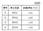
- the stop position data for specifying the stop positions ST11, ST12, ST13, ST14 is the following first stop position data D100.
- FIG. 9 is a diagram showing first stop position data D100 as an example.
- the first stop position data D100 is composed of four pieces of stop data.
- “number” is a number for specifying stop data.
- the “stop position” is the stop position described with reference to FIG.
- the “distance” is a distance from a point P12 on the travel path L10 shown in FIG. 1, FIG. 8A or FIG. 8B to a corresponding stop position.
- the stop data with the number “1” indicates that the distance from the point P12 on the travel path L10 to the stop position ST11 is L11 (eg, 1200 mm). That is, the first stop position data D100 indicates each stop position between successive points P12 and P13 on the travel path L10 shown in FIG.
- the stop position data for specifying the stop positions ST21, ST22, ST23 is the following second stop position data D200.
- FIG. 10 is a diagram showing second stop position data D200 as an example.
- the second stop position data D200 is composed of three pieces of stop data.
- the second stop position data D200 indicates each stop position between the continuous points P12 and P13 on the travel path L10 shown in FIG. 8B.
- the stop data with the number “3” has a distance L23 (for example, 1800 mm) from the point P12 on the travel path L10 in FIG. 8B to the stop position ST23. Indicates that there is.
- the first stop position data D100 in FIG. 9 and the second stop position data D200 in FIG. 10 are stored in advance in the storage unit 220 of the transport vehicle 200.
- the buffer device 420 When the buffer device 420 is attached to the manufacturing device 410, it is assumed that the device to which the transport vehicle 200 transports the cassette C11 is the buffer device 420.
- FIG. 11 is a diagram illustrating processing performed in each of the MES 50, the ground controller 100, the transport vehicle 200, the buffer device 420, and the manufacturing apparatus 410 when the buffer apparatus 420 is detached from the manufacturing apparatus 410.
- the MES 50 transmits a manufacturing apparatus transport command to the ground controller 100 (S51).
- the manufacturing apparatus transport instruction is a transport instruction for causing the transport vehicle 200 to transport the cassette C11 to the manufacturing apparatus 410. That is, the manufacturing apparatus transport instruction is an instruction for causing the transport vehicle 200 to transport the cassette C11 to any one of the load ports PT21, PT22, and PT23 associated with the manufacturing apparatus 410.
- the control unit 110 sends the buffer device transport command to the transport vehicle 200. (S111).
- the removal advance notice information is information for notifying that the buffer device 420 is removed from the manufacturing apparatus 410 after at least a predetermined time (for example, 3 minutes) has elapsed.
- the controller 110 does not receive the removal notice information between the time when the manufacturing apparatus transport command is received and before the predetermined time elapses, the buffer device 420 is attached to the manufacturing apparatus 410.
- the buffer device transport command is a transport command for causing the transport vehicle 200 to transport the cassette C11 to the buffer device 420.
- the control part 110 transmits a buffer apparatus conveyance command to the conveyance vehicle 200, when the removal advance notice information is not received.
- the buffer device transfer command includes load port information.
- the load port information indicates, for example, a load port to be subjected to an operation for placing the cassette C11.
- the load port information indicates operation information.
- the operation information is information indicating an operation of loading, for example, the cassette C11 for the load port indicated by the load port information.
- the control unit 210 transmits the cassette C11 to the buffer device 420, in order to transport the cassette C11 to the buffer device 420, among the four stop positions indicated by the first stop position data D100. Control for stopping the transport vehicle 200 is performed at the stop position corresponding to the load port (for example, the load port PT11) indicated by the included load port information.
- the transport vehicle 200 moves to the stop position corresponding to the load port indicated by the load port information, then stops at the stop position, and performs the operation indicated by the operation information indicated by the load port information.
- the work is, for example, a work of pressing a button provided outside the manufacturing apparatus 410. With this operation, the manufacturing apparatus 410 stops operating (S411).
- the removal notice work is, for example, a work of pressing a removal notice button (not shown) provided outside the buffer device 420.
- the removal notice button is a button for transmitting the above-described removal notice information to the ground controller 100 when pressed.
- the computer (not shown) of the buffer device 420 transmits the removal notice information to the ground controller 100 (S421).
- the control unit 110 of the ground controller 100 transmits port down notification information to the transport vehicle 200 (S112).
- the port down notification information is information indicating that the transfer of the cassette to the load port included in the buffer device 420 and the load port associated with the manufacturing device 410 is not permitted. That is, the port down notification information is information for reporting a load port whose use is not permitted (hereinafter referred to as a use-unpermitted load port).
- the unusable load port is, for example, a load port that the buffer device 420 has and a load port that is associated with the manufacturing device 410.
- the port down notification information also indicates an unusable load port.
- the control unit 210 of the transport vehicle 200 Upon receiving the port down notification information, the control unit 210 of the transport vehicle 200 performs a port down process (S211). In the port down process, the port down is set. Specifically, the control unit 210 causes the storage unit 220 to store information indicating that use of the load port indicated by the port down notification information is not permitted (hereinafter referred to as port down information).
- the port down information indicates information for specifying a load port that is not allowed to be used.
- the port down information is stored in the storage unit 220, the port down is set.
- the control unit 210 of the transport vehicle 200 When receiving the port-down notification information, the control unit 210 of the transport vehicle 200 places the cassette on the non-permitted load port indicated by the port-down notification information and sets the use-unpermitted load port until the port-down notification is canceled.
- the conveyance vehicle 200 is controlled so that the conveyance vehicle 200 does not perform the process of lifting the cassette placed thereon.
- the operator performs the work for stopping the operation of the buffer device 420 after performing the removal notice work, and removes the buffer device 420 from the manufacturing device 410 (S422).
- the operator uses the input unit 140 of the ground controller 100 to perform a stop position switching operation. That is, the input unit 140 receives a stop position switching operation (S113).
- the stop position switching operation is an operation for causing the transport vehicle 200 to use the second stop position data D200.
- the operator performs an operation for operating the manufacturing apparatus 410 whose operation is stopped.
- the work is, for example, a work of pressing a button provided outside the manufacturing apparatus 410. With this operation, the manufacturing apparatus 410 starts operating (S412).
- the control unit 110 of the ground controller 100 transmits setting switching data to the transport vehicle 200 (S114).
- the setting switching data is data indicating an instruction for setting the stop position data used by the transport vehicle 200 to the second stop position data D200.
- the control unit 210 of the transport vehicle 200 When receiving the setting switching data via the communication unit 270, the control unit 210 of the transport vehicle 200 performs a setting switching process (S212). In the setting switching process, the control unit 210 sets the stop position data to be used in the second stop position data D200.
- the controller 210 transmits a setting completion notification to the ground controller 100 (S213).
- the setting completion notification is a notification that processing for setting the stop position data used by the transport vehicle 200 to the second stop position data D200 is completed.
- the control part 210 performs a port down cancellation
- the port down release process is a process for releasing the port down. Specifically, the control unit 210 deletes the port down information stored in the storage unit 220. As a result, the use of the unusable load port is permitted. That is, the port down setting is canceled.
- control unit 110 of the ground controller 100 Upon receiving the setting completion notification, the control unit 110 of the ground controller 100 transmits the received setting completion notification to the MES 50 (S115).
- the MES 50 knows that the stop position data used by the transport vehicle 200 is set in the second stop position data D200 by receiving the setting completion notification.
- control unit 110 of the ground controller 100 After transmitting the setting completion notification, the control unit 110 of the ground controller 100 performs a transport command target switching process (S116).
- the control unit 110 receives a manufacturing apparatus transfer instruction from the MES 50, the apparatus that is the target of the transfer instruction as the received manufacturing apparatus transfer instruction is switched from the buffer device 420 to the manufacturing apparatus 410. .
- the conveyance command object switching process is a process for switching the apparatus (conveyance object apparatus) to which the conveyance vehicle 200 conveys the cassette C11 from the buffer apparatus 420 to the manufacturing apparatus 410.
- the control unit 110 receives a manufacturing apparatus transport command from the MES 50, the control unit 110 transmits the received manufacturing apparatus transport command to the transport vehicle 200.
- control part 110 of the ground controller 100 receives a manufacturing apparatus conveyance command.
- the control unit 110 transmits the received manufacturing apparatus transport command to the transport vehicle 200 ( S117).
- the manufacturing device transport instruction includes load port information.
- the load port information indicates, for example, a load port to be subjected to an operation for placing the cassette C11.
- the load port information indicates operation information.
- the operation information is information indicating an operation of loading, for example, the cassette C11 for the load port indicated by the load port information.
- the control unit 210 of the transport vehicle 200 When receiving the manufacturing apparatus transport instruction, the control unit 210 of the transport vehicle 200 performs a stop process (S215). In the stop process, the control unit 210 loads the load indicated by the load port information included in the manufacturing apparatus transport instruction among the three stop positions indicated by the second stop position data D200 in order to transport the cassette C11 to the manufacturing apparatus 410. Control for stopping the transport vehicle 200 is performed at a stop position (for example, stop position ST21) corresponding to the port (for example, load port PT21).
- a stop position for example, stop position ST21
- the port for example, load port PT21
- the transport vehicle 200 moves to the stop position corresponding to the load port indicated by the load port information, then stops at the stop position, and performs the operation indicated by the operation information indicated by the load port information.
- route down may be performed instead of the port down described above.
- the route down is a process for disallowing traveling on a part of the traveling path (for example, traveling path L10) on which the transport vehicle 200 travels.
- a travel path that is not permitted to travel is referred to as a route down travel path.
- the control unit 210 of the transport vehicle 200 controls the transport vehicle 200 so as not to travel on the route down travel path.
- the controller 210 When the transport vehicle 200 cannot be transported to the buffer device 420 due to port down or route down while the transport vehicle 200 is transporting the cassette C11 to the buffer device 420, the controller 210 temporarily Then, the transport vehicle 200 is set to an error state.
- the ground controller 100 transmits a primary storage command to the transport vehicle 200.
- the primary storage command is a command for placing the cassette C11 on the ceiling buffer BU10 of FIG. 5 described above.
- the transport vehicle 200 When receiving the primary storage instruction, the transport vehicle 200 temporarily places the cassette C11 on the ceiling buffer BU10. Then, when the ground controller 100 is able to transport the cassette C11 to the manufacturing apparatus 410, for example, when the port down or the route down is canceled, the ground controller 100 is placed on the ceiling buffer BU10. A command for transporting C11 to the manufacturing apparatus 410 is transmitted to the transport vehicle 200.
- the transport vehicle 200 transports the cassette C11 placed on the ceiling buffer BU10 to the manufacturing apparatus 410 in response to receiving the command.
- the manufacturing apparatus 410 is in operation. Further, it is assumed that the stop position data used by the transport vehicle 200 is set to the second stop position data D200 by the setting switching process described above. Further, it is assumed that the apparatus that is the target of the transport command in the ground controller 100 is set in the manufacturing apparatus 410 by the above-described transport command target switching process.
- FIG. 12 is a diagram illustrating processing performed in each of the MES 50, the ground controller 100, the transport vehicle 200, the buffer device 420, and the manufacturing apparatus 410 when the buffer apparatus 420 is attached to the manufacturing apparatus 410.
- the MES 50 transmits a manufacturing apparatus transport command to the ground controller 100 (S51A).
- the manufacturing apparatus transport instruction is a transport instruction for causing the transport vehicle 200 to transport the cassette C11 to the manufacturing apparatus 410. That is, the manufacturing apparatus transport instruction is an instruction for causing the transport vehicle 200 to transport the cassette C11 to any one of the load ports PT21, PT22, and PT23 associated with the manufacturing apparatus 410.
- control part 110 of the ground controller 100 receives a manufacturing apparatus conveyance command.
- the control unit 110 transmits the received manufacturing apparatus transport command to the transport car 200 (S111A).
- the manufacturing device transport instruction includes load port information.
- the load port information indicates, for example, a load port to be subjected to an operation for placing the cassette C11.
- the load port information indicates operation information.
- the operation information is information indicating an operation of loading, for example, the cassette C11 for the load port indicated by the load port information.
- control unit 210 of the transport vehicle 200 When the control unit 210 of the transport vehicle 200 receives the manufacturing apparatus transport command, the control unit 210 includes the three stop positions indicated by the second stop position data D200 in order to transport the cassette C11 to the manufacturing apparatus 410. Control for stopping the transport vehicle 200 is performed at a stop position (for example, stop position ST21) corresponding to a load port (for example, load port PT21) indicated by the load port information included in the manufacturing apparatus transport instruction.
- a stop position for example, stop position ST21
- load port for example, load port PT21
- the transport vehicle 200 moves to the stop position corresponding to the load port indicated by the load port information, then stops at the stop position, and performs the operation indicated by the operation information indicated by the load port information.
- the operator performs an operation for stopping the operation of the manufacturing apparatus 410.
- the manufacturing apparatus 410 stops operating (S411).
- the attachment advancement work is, for example, an operation of pressing an attachment advancement button (not shown) provided outside the buffer device 420.
- the attachment advance notice button is a button for transmitting attachment advance notice information to the ground controller 100 when pressed.
- the attachment advance notice information is information for notifying that the buffer device 420 is attached to the manufacturing device 410 after at least a predetermined time (for example, 3 minutes) has elapsed.
- the computer (not shown) of the buffer device 420 transmits the attachment advancement information to the ground controller 100 (S421A).
- control unit 110 of the ground controller 100 When the control unit 110 of the ground controller 100 receives the attachment advance notice information, it transmits the above-described port down notification information to the transport vehicle 200 (S112).
- the control unit 210 of the transport vehicle 200 Upon receiving the port down notification information, the control unit 210 of the transport vehicle 200 performs a port down process (S211). Since the port down process has been described above, detailed description will not be repeated.
- the operator attaches the buffer device 420 to the manufacturing device 410 and performs an operation for resuming the operation of the buffer device 420 (S422A).
- the operator performs a stop position switching operation A using the input unit 140 of the ground controller 100. That is, the input unit 140 receives the stop position switching operation A (S113A).
- the stop position switching operation A is an operation for causing the transport vehicle 200 to use the first stop position data D100.
- the operator performs an operation for operating the manufacturing apparatus 410 whose operation is stopped.
- the work is, for example, a work of pressing a button provided outside the manufacturing apparatus 410. With this operation, the manufacturing apparatus 410 starts operating (S412).
- the setting switching data A is data indicating an instruction for setting the stop position data used by the transport vehicle 200 to the first stop position data D100.
- the control unit 210 of the transport vehicle 200 When receiving the setting switching data A via the communication unit 270, the control unit 210 of the transport vehicle 200 performs a setting switching process A (S212A). In the setting switching process A, the control unit 210 sets the stop position data to be used in the second stop position data D200. Then, the control unit 210 transmits a setting completion notification A to the ground controller 100 (S213A).
- the setting completion notification A is a notification that processing for setting the stop position data used by the transport vehicle 200 to the first stop position data D100 is completed.
- control part 210 performs a port down cancellation
- the control unit 110 of the ground controller 100 transmits the received setting completion notification A to the MES 50 (S115A).
- the MES 50 By receiving the setting completion notification A, the MES 50 knows that the stop position data used by the transport vehicle 200 is set in the first stop position data D100.
- control unit 110 of the ground controller 100 After transmitting the setting completion notification A, the control unit 110 of the ground controller 100 performs the conveyance command target switching process A (S116A).
- the transfer instruction target switching process A when the control unit 110 receives a manufacturing apparatus transfer instruction from the MES 50, the apparatus that is the target of the transfer instruction as the received manufacturing apparatus transfer instruction is transferred from the manufacturing apparatus 410 to the buffer apparatus 420.
- the conveyance command target switching process A is a process for switching the apparatus to which the conveyance vehicle 200 is to convey the cassette C11 from the manufacturing apparatus 410 to the buffer apparatus 420.
- the control unit 110 transmits the buffer apparatus transport instruction described above to the transport vehicle 200.
- control part 110 of the ground controller 100 receives a manufacturing apparatus conveyance command.
- the apparatus to which the transport vehicle 200 transports the cassette C11 is the buffer device 420, and therefore the control unit 110 transmits a buffer device transport command to the transport vehicle 200 (S117A).
- the buffer device transfer command includes load port information.
- the load port information indicates, for example, a load port to be subjected to an operation for placing the cassette C11.
- the load port information indicates operation information.
- the operation information is information indicating an operation of loading, for example, the cassette C11 for the load port indicated by the load port information.
- the control unit 210 of the transport vehicle 200 When receiving the buffer device transport instruction, the control unit 210 of the transport vehicle 200 performs a stop process A (S215A). In the stop process A, in order to transport the cassette C11 to the buffer device 420, the control unit 210 indicates the load port information included in the buffer device transport command among the four stop positions indicated by the first stop position data D100. Control for stopping the transport vehicle 200 is performed at a stop position corresponding to the load port (for example, the load port PT11).
- the transport vehicle 200 moves to the stop position corresponding to the load port indicated by the load port information, then stops at the stop position, and performs the operation indicated by the operation information indicated by the load port information.
- the stop position data corresponding to the changed device to which the transport vehicle 200 is to transport the cassette C11 is transported. Only by setting the vehicle 200 to be used, the transport vehicle 200 can stop at a stop position corresponding to the changed device.
- the transport vehicle 200 since the transport vehicle 200 stores the first stop position data D100 and the second stop position data D200 in advance, it is not necessary for the operator to adjust the stop position data indicating the stop position of the transport vehicle.
- the route down period after the apparatus 420 is removed from the manufacturing apparatus 410 or the buffer apparatus 420 is attached to the manufacturing apparatus 410 can be very short. That is, the line recovery time can be greatly shortened.
- the first stop position data D100 and the second stop position data D200 are stored in the storage unit 220 of the transport vehicle 200 in advance.
- the ground controller 100 may store the first stop position data D100 and the second stop position data D200. And the ground controller 100 may transmit the 1st stop position data D100 or the 2nd stop position data D200 to the conveyance vehicle 200 as needed.
- FIG. 13 is a block diagram showing a characteristic functional configuration of the transport system 1000 according to the present invention. That is, FIG. 13 shows functions related to the present invention among the functions of the ground controller 100 realized by the hardware configuration shown in FIG. 6 and the functions of the transport vehicle 200 realized by the hardware configuration shown in FIG. FIG.
- FIG. 13 shows the control unit 110, the input unit 140, the control unit 210, and the communication unit 270 for explanation.
- the control unit 110 of the ground controller 100 functionally includes a transmission unit 111.
- the control unit 210 of the transport vehicle 200 functionally includes a stop control unit 211.
- the transmission unit 111 is configured such that the first data for stopping the transport vehicle 200 at the first stop position where the article can be placed on the buffer device 420 or the second stop position where the transport vehicle 200 is associated with the first device.
- the second data for stopping is transmitted to the transport vehicle 200.
- the communication unit 270 of the transport vehicle 200 receives the first data or the second data.
- the stop control unit 211 performs control to stop the transport vehicle 200 at the first stop position when the first data is received, and performs control to stop the transport vehicle 200 at the second stop position when the second data is received. Do.
- the transmission unit 111 receives the first setting switching data for causing the transport vehicle 200 to use the first stop position data.
- the second setting switch for causing the transport vehicle 200 to use the second stop position data is transmitted. Data is transmitted to the transport vehicle 200.
- control unit 210 of the transport vehicle 200 functionally includes a setting unit 212.
- the setting unit 212 sets the stop control unit 211 to use the first stop position data, and when the communication unit 270 receives the second setting switching data.
- the stop control unit 211 is set to use the second stop position data.
- the transmission unit 111 included in the control unit 110 may be configured with hardware.
- the transmission unit 111 may be a module of a program executed by the control unit 110.
- stop control unit 211 and the setting unit 212 included in the control unit 210 may be configured by hardware. Further, all or a part of the stop control unit 211 and the setting unit 212 may be a module of a program executed by the control unit 210.
- the present invention can be used as a transport system that can quickly switch the stop position of the transport vehicle.
Landscapes
- Engineering & Computer Science (AREA)
- Mechanical Engineering (AREA)
- Container, Conveyance, Adherence, Positioning, Of Wafer (AREA)
- Warehouses Or Storage Devices (AREA)
- Control Of Position, Course, Altitude, Or Attitude Of Moving Bodies (AREA)
Abstract
Description
図1は、本実施の形態における搬送システム1000の構成を示す図である。なお、図1には、説明の都合上、搬送システム1000に含まれないMES(Manufacturing Execution System)50を示している。
図13は、本発明に係る搬送システム1000の特徴的な機能構成を示すブロック図である。つまり、図13は、図6に示されるハードウエア構成によって実現される地上コントローラ100の機能および図7に示されるハードウエア構成によって実現される搬送車200の機能のうち、本発明に関わる機能を示すブロック図である。
50 MES
100 地上コントローラ
110,210 制御部
120,220 記憶部
140 入力部
170,270 通信部
200 搬送車
410 製造装置
420 バッファ装置
1000 搬送システム
Claims (4)
- 予め定められた走行路と、前記走行路を走行することにより第1の装置に対して物品を搬送可能な搬送車と、前記搬送車を制御するコントローラとを含む搬送システムであって、
前記搬送システムは、さらに、
前記第1の装置に対し着脱可能な装置であって、前記搬送車が物品を載せることが可能な第2の装置を含み、
前記コントローラは、
前記搬送車が前記第2の装置に物品を載せることが可能な第1停止位置に停止するための第1データまたは前記搬送車が前記第1の装置に対応づけられた第2停止位置に停止するための第2データを前記搬送車へ送信する送信部を備え、
前記搬送車は、
前記第1データまたは第2データを受信する通信部と、
前記第1データを受信した場合、前記搬送車を前記第1停止位置に停止させる制御を行い、前記第2データを受信した場合、前記搬送車を前記第2停止位置に停止させる制御を行う停止制御部と
を備える、搬送システム。 - 前記搬送車は、さらに、
前記第1停止位置を示す第1停止位置データと、前記第2停止位置を示す第2停止位置データとを記憶する記憶部を備え、
前記コントローラは、さらに、
オペレーターの操作を受け付ける入力部を備え、
前記コントローラの前記送信部は、前記入力部が前記搬送車に前記第1停止位置データを使用させるための操作を受け付けた場合、前記搬送車に前記第1停止位置データを使用させるための第1設定切替データを前記搬送車へ送信し、前記入力部が前記搬送車に前記第2停止位置データを使用させるための操作を受け付けた場合、前記搬送車に前記第2停止位置データを使用させるための第2設定切替データを前記搬送車へ送信し、
前記搬送車は、さらに、
前記通信部が前記第1設定切替データを受信した場合、前記停止制御部が前記第1停止位置データを使用するように設定し、前記通信部が前記第2設定切替データを受信した場合、前記停止制御部が前記第2停止位置データを使用するように設定する設定部を備え、
前記コントローラの前記送信部は、前記第1設定切替データを送信している場合、前記搬送車を前記第1停止位置に停止させるための命令としての前記第1データを前記搬送車へ送信し、前記第2設定切替データを送信している場合、前記搬送車を前記第2停止位置に停止させるための命令としての前記第2データを前記搬送車へ送信し、
前記搬送車の前記停止制御部は、前記第1データを受信した場合、前記第1停止位置データが示す前記第1停止位置に前記搬送車を停止させる制御を行い、前記第2データを受信した場合、前記第2停止位置データが示す前記第2停止位置に前記搬送車を停止させる制御を行う、
請求項1に記載の搬送システム。 - 前記第1データは、前記走行路上の連続する第1ポイントから第2ポイントの間において、前記第1ポイントから第1距離だけ離れた位置である前記第1停止位置を示し、
前記第2データは、前記第1ポイントから前記第1距離と異なる第2距離だけ離れた位置である前記第2停止位置を示し、
前記送信部は、前記第1データまたは前記第2データを前記搬送車へ送信する、
請求項1に記載の搬送システム。 - 前記第2の装置は、前記第1の装置から搬出された物品または前記第1の装置へ供給する物品を保管するための装置であり、
前記第1データは、複数の前記第1停止位置を示し、
前記第2データは、複数の前記第2停止位置を示し、
前記第1データが示す前記第1停止位置の数は、前記第2データが示す前記第2停止位置の数と異なる、
請求項1または3に記載の搬送システム。
Priority Applications (6)
| Application Number | Priority Date | Filing Date | Title |
|---|---|---|---|
| US13/254,834 US8527088B2 (en) | 2009-03-03 | 2010-02-15 | Transportation system |
| JP2011502613A JP5267653B2 (ja) | 2009-03-03 | 2010-02-15 | 搬送システム |
| EP10748438.8A EP2404846B1 (en) | 2009-03-03 | 2010-02-15 | Transfer system |
| CN201080010314.XA CN102341324B (zh) | 2009-03-03 | 2010-02-15 | 搬送系统 |
| SG2011063153A SG174209A1 (en) | 2009-03-03 | 2010-02-15 | Transportation system |
| KR1020117019178A KR101341403B1 (ko) | 2009-03-03 | 2010-02-15 | 반송 시스템 |
Applications Claiming Priority (2)
| Application Number | Priority Date | Filing Date | Title |
|---|---|---|---|
| JP2009-049983 | 2009-03-03 | ||
| JP2009049983 | 2009-03-03 |
Publications (1)
| Publication Number | Publication Date |
|---|---|
| WO2010100834A1 true WO2010100834A1 (ja) | 2010-09-10 |
Family
ID=42709407
Family Applications (1)
| Application Number | Title | Priority Date | Filing Date |
|---|---|---|---|
| PCT/JP2010/000900 Ceased WO2010100834A1 (ja) | 2009-03-03 | 2010-02-15 | 搬送システム |
Country Status (8)
| Country | Link |
|---|---|
| US (1) | US8527088B2 (ja) |
| EP (1) | EP2404846B1 (ja) |
| JP (1) | JP5267653B2 (ja) |
| KR (1) | KR101341403B1 (ja) |
| CN (1) | CN102341324B (ja) |
| SG (1) | SG174209A1 (ja) |
| TW (1) | TWI471711B (ja) |
| WO (1) | WO2010100834A1 (ja) |
Cited By (4)
| Publication number | Priority date | Publication date | Assignee | Title |
|---|---|---|---|---|
| JP2015213318A (ja) * | 2014-05-02 | 2015-11-26 | オ,ハクソ | 自動搬送システム用のデータ伝送システム |
| WO2023189069A1 (ja) | 2022-03-29 | 2023-10-05 | 村田機械株式会社 | 搬送システム |
| WO2024244317A1 (zh) * | 2023-05-31 | 2024-12-05 | 西安奕斯伟材料科技股份有限公司 | 半导体物料搬送的控制方法、装置、设备、介质及产品 |
| JP7688439B1 (ja) | 2023-11-21 | 2025-06-04 | カントプス カンパニー リミテッド | 天井型自動搬送システムの搬送台車位置認識方法 |
Families Citing this family (10)
| Publication number | Priority date | Publication date | Assignee | Title |
|---|---|---|---|---|
| EP2835325B1 (en) * | 2012-04-05 | 2018-09-05 | Murata Machinery, Ltd. | Conveyance system |
| NL2011021C2 (nl) * | 2013-06-21 | 2014-12-24 | Vanderlande Ind Bv | Systeem voor het opslaan van producthouders en werkwijze voor toepassing van een dergelijk systeem. |
| WO2015186440A1 (ja) * | 2014-06-02 | 2015-12-10 | 村田機械株式会社 | 走行車システム及び走行車の制御方法 |
| CN106463441B (zh) * | 2014-06-19 | 2019-04-23 | 村田机械株式会社 | 载具的临时保管装置和临时保管方法 |
| JP6135637B2 (ja) * | 2014-10-20 | 2017-05-31 | 村田機械株式会社 | 走行車システム |
| WO2017010183A1 (ja) * | 2015-07-15 | 2017-01-19 | 村田機械株式会社 | 搬送制御装置及び搬送制御システム |
| CN105173504A (zh) * | 2015-09-29 | 2015-12-23 | 扬中中科维康智能科技有限公司 | 一种自动仓储机器人系统 |
| SG11202008642UA (en) * | 2018-03-15 | 2020-10-29 | Murata Machinery Ltd | Traveling vehicle controller and traveling vehicle system |
| US11339008B2 (en) * | 2018-03-27 | 2022-05-24 | Murata Machinery, Ltd. | Transport system, transport controller, and transport vehicle control method |
| CN111788106B (zh) * | 2018-05-01 | 2022-07-26 | 村田机械株式会社 | 输送系统 |
Citations (2)
| Publication number | Priority date | Publication date | Assignee | Title |
|---|---|---|---|---|
| JPS63189907A (ja) * | 1987-02-02 | 1988-08-05 | Toshiba Corp | 無人搬送車 |
| JP2006051866A (ja) * | 2004-08-10 | 2006-02-23 | Toyota Motor Corp | シャーシフレームを備えた車両の車体構造 |
Family Cites Families (8)
| Publication number | Priority date | Publication date | Assignee | Title |
|---|---|---|---|---|
| JPH08318486A (ja) * | 1995-05-23 | 1996-12-03 | Hitachi Ltd | 自動搬送装置の制御方法 |
| JP2000181542A (ja) * | 1998-12-14 | 2000-06-30 | Hitachi Kiden Kogyo Ltd | 自動搬送システムにおける搬送車の停止方法 |
| US20050095087A1 (en) * | 2003-10-30 | 2005-05-05 | Sullivan Robert P. | Automated material handling system |
| JP4074999B2 (ja) | 2004-01-13 | 2008-04-16 | 村田機械株式会社 | 搬送台車システム |
| JP2006051886A (ja) | 2004-08-12 | 2006-02-23 | Murata Mach Ltd | 天井走行車システム |
| JP4464993B2 (ja) * | 2007-06-29 | 2010-05-19 | 東京エレクトロン株式会社 | 基板の処理システム |
| US8235000B2 (en) * | 2008-05-09 | 2012-08-07 | Caterpillar Inc. | Modular paint line and method of operation therefor |
| WO2010073446A1 (ja) * | 2008-12-26 | 2010-07-01 | 村田機械株式会社 | 走行車システム |
-
2010
- 2010-02-15 US US13/254,834 patent/US8527088B2/en active Active
- 2010-02-15 SG SG2011063153A patent/SG174209A1/en unknown
- 2010-02-15 KR KR1020117019178A patent/KR101341403B1/ko active Active
- 2010-02-15 EP EP10748438.8A patent/EP2404846B1/en active Active
- 2010-02-15 WO PCT/JP2010/000900 patent/WO2010100834A1/ja not_active Ceased
- 2010-02-15 JP JP2011502613A patent/JP5267653B2/ja active Active
- 2010-02-15 CN CN201080010314.XA patent/CN102341324B/zh active Active
- 2010-03-03 TW TW99106153A patent/TWI471711B/zh active
Patent Citations (2)
| Publication number | Priority date | Publication date | Assignee | Title |
|---|---|---|---|---|
| JPS63189907A (ja) * | 1987-02-02 | 1988-08-05 | Toshiba Corp | 無人搬送車 |
| JP2006051866A (ja) * | 2004-08-10 | 2006-02-23 | Toyota Motor Corp | シャーシフレームを備えた車両の車体構造 |
Cited By (7)
| Publication number | Priority date | Publication date | Assignee | Title |
|---|---|---|---|---|
| JP2015213318A (ja) * | 2014-05-02 | 2015-11-26 | オ,ハクソ | 自動搬送システム用のデータ伝送システム |
| WO2023189069A1 (ja) | 2022-03-29 | 2023-10-05 | 村田機械株式会社 | 搬送システム |
| JPWO2023189069A1 (ja) * | 2022-03-29 | 2023-10-05 | ||
| KR20240164942A (ko) | 2022-03-29 | 2024-11-21 | 무라다기카이가부시끼가이샤 | 반송 시스템 |
| WO2024244317A1 (zh) * | 2023-05-31 | 2024-12-05 | 西安奕斯伟材料科技股份有限公司 | 半导体物料搬送的控制方法、装置、设备、介质及产品 |
| JP7688439B1 (ja) | 2023-11-21 | 2025-06-04 | カントプス カンパニー リミテッド | 天井型自動搬送システムの搬送台車位置認識方法 |
| JP2025089239A (ja) * | 2023-11-21 | 2025-06-12 | カントプス カンパニー リミテッド | 天井型自動搬送システムの搬送台車位置認識方法 |
Also Published As
| Publication number | Publication date |
|---|---|
| TWI471711B (zh) | 2015-02-01 |
| CN102341324A (zh) | 2012-02-01 |
| US20120004767A1 (en) | 2012-01-05 |
| CN102341324B (zh) | 2013-07-10 |
| JP5267653B2 (ja) | 2013-08-21 |
| EP2404846A4 (en) | 2014-07-30 |
| TW201033098A (en) | 2010-09-16 |
| US8527088B2 (en) | 2013-09-03 |
| SG174209A1 (en) | 2011-10-28 |
| KR101341403B1 (ko) | 2013-12-13 |
| JPWO2010100834A1 (ja) | 2012-09-06 |
| KR20110118674A (ko) | 2011-10-31 |
| EP2404846B1 (en) | 2019-04-03 |
| EP2404846A1 (en) | 2012-01-11 |
Similar Documents
| Publication | Publication Date | Title |
|---|---|---|
| JP5267653B2 (ja) | 搬送システム | |
| TWI685460B (zh) | 用於自動化晶圓處理的系統及方法 | |
| TWI702575B (zh) | 縮短自動搬運系統作業時間的資料通信方法 | |
| JP2005150129A (ja) | 移載装置及び移載システム | |
| KR20080009092A (ko) | 자동 재료 취급 시스템 | |
| JP2010184760A (ja) | 移載システム | |
| CN114126988B (zh) | 搬送车 | |
| WO2020049872A1 (ja) | 搬送車システム | |
| JP2005001886A (ja) | 搬送システム及びそれに用いられる保管装置 | |
| JP2020524647A (ja) | コンベアシステムを稼働させるコンベアシステム方法及びそのコンベアシステムにおいて用いられるフロー装置 | |
| CN113841099B (zh) | 行驶车系统及行驶车的控制方法 | |
| JP2010080904A (ja) | 自動化ウェハ一時保管システムとその制御方法 | |
| TW202021382A (zh) | 移行系統及移行系統之控制方法 | |
| CN117125427A (zh) | 物品搬送设备 | |
| CN113611651B (zh) | 半导体制造设备系统及其操作方法 | |
| KR20150020757A (ko) | 기판 처리 시스템 및 이의 제어 방법 | |
| KR102221115B1 (ko) | 이송 장치의 제어 방법 | |
| KR102825738B1 (ko) | 기판 이송 장치 및 기판 이송 방법 | |
| JP4182874B2 (ja) | 台車制御装置及び制御方法 | |
| KR102868907B1 (ko) | 반송 시스템 | |
| TWI903809B (zh) | 用於處理電子元件的處理機 | |
| JP2009051307A (ja) | 無人搬送車、該無人搬送車を備えた搬送移載システム、及び搬送移載方法 | |
| JP2000293232A (ja) | 自動搬送システム | |
| KR20050076584A (ko) | 무인 반송 시스템의 최적 반송 제어 방법 | |
| JPH06224094A (ja) | 半導体基板の製造工程における工程間搬送システム |
Legal Events
| Date | Code | Title | Description |
|---|---|---|---|
| WWE | Wipo information: entry into national phase |
Ref document number: 201080010314.X Country of ref document: CN |
|
| 121 | Ep: the epo has been informed by wipo that ep was designated in this application |
Ref document number: 10748438 Country of ref document: EP Kind code of ref document: A1 |
|
| ENP | Entry into the national phase |
Ref document number: 20117019178 Country of ref document: KR Kind code of ref document: A |
|
| WWE | Wipo information: entry into national phase |
Ref document number: 2011502613 Country of ref document: JP |
|
| WWE | Wipo information: entry into national phase |
Ref document number: 2010748438 Country of ref document: EP |
|
| WWE | Wipo information: entry into national phase |
Ref document number: 13254834 Country of ref document: US |
|
| NENP | Non-entry into the national phase |
Ref country code: DE |