WO2010098192A1 - ターボ分子ポンプおよびターボ分子ポンプ用パーティクルトラップ - Google Patents
ターボ分子ポンプおよびターボ分子ポンプ用パーティクルトラップ Download PDFInfo
- Publication number
- WO2010098192A1 WO2010098192A1 PCT/JP2010/051686 JP2010051686W WO2010098192A1 WO 2010098192 A1 WO2010098192 A1 WO 2010098192A1 JP 2010051686 W JP2010051686 W JP 2010051686W WO 2010098192 A1 WO2010098192 A1 WO 2010098192A1
- Authority
- WO
- WIPO (PCT)
- Prior art keywords
- rotor
- molecular pump
- turbo molecular
- mesh structure
- blades
- Prior art date
- Legal status (The legal status is an assumption and is not a legal conclusion. Google has not performed a legal analysis and makes no representation as to the accuracy of the status listed.)
- Ceased
Links
Images




Classifications
-
- F—MECHANICAL ENGINEERING; LIGHTING; HEATING; WEAPONS; BLASTING
- F04—POSITIVE - DISPLACEMENT MACHINES FOR LIQUIDS; PUMPS FOR LIQUIDS OR ELASTIC FLUIDS
- F04D—NON-POSITIVE-DISPLACEMENT PUMPS
- F04D29/00—Details, component parts, or accessories
- F04D29/70—Suction grids; Strainers; Dust separation; Cleaning
- F04D29/701—Suction grids; Strainers; Dust separation; Cleaning especially adapted for elastic fluid pumps
-
- F—MECHANICAL ENGINEERING; LIGHTING; HEATING; WEAPONS; BLASTING
- F04—POSITIVE - DISPLACEMENT MACHINES FOR LIQUIDS; PUMPS FOR LIQUIDS OR ELASTIC FLUIDS
- F04D—NON-POSITIVE-DISPLACEMENT PUMPS
- F04D29/00—Details, component parts, or accessories
-
- F—MECHANICAL ENGINEERING; LIGHTING; HEATING; WEAPONS; BLASTING
- F04—POSITIVE - DISPLACEMENT MACHINES FOR LIQUIDS; PUMPS FOR LIQUIDS OR ELASTIC FLUIDS
- F04D—NON-POSITIVE-DISPLACEMENT PUMPS
- F04D19/00—Axial-flow pumps
- F04D19/02—Multi-stage pumps
- F04D19/04—Multi-stage pumps specially adapted to the production of a high vacuum, e.g. molecular pumps
-
- F—MECHANICAL ENGINEERING; LIGHTING; HEATING; WEAPONS; BLASTING
- F04—POSITIVE - DISPLACEMENT MACHINES FOR LIQUIDS; PUMPS FOR LIQUIDS OR ELASTIC FLUIDS
- F04D—NON-POSITIVE-DISPLACEMENT PUMPS
- F04D19/00—Axial-flow pumps
- F04D19/02—Multi-stage pumps
- F04D19/04—Multi-stage pumps specially adapted to the production of a high vacuum, e.g. molecular pumps
- F04D19/042—Turbomolecular vacuum pumps
Definitions
- the present invention relates to a turbo molecular pump and a particle trap for the turbo molecular pump.
- Turbo molecular pumps are used in etching processes and CVD processes such as semiconductor production.
- particles such as reaction products flow into the turbo molecular pump from the vacuum chamber in which these processes are performed, the particles may be splashed by the rotor rotating at high speed, and the recoil particles may reach the vacuum chamber.
- recoil particles adhere to the wafer and deteriorate the production yield of the semiconductor.
- Patent Document 1 As configurations for reducing the backflow of recoil particles to the vacuum chamber, configurations as described in Patent Documents 1 to 3 have been proposed.
- Patent Document 1 a small chamber for capturing particles is provided on the inner peripheral surface of the pump casing, and the particles are splashed off in the direction of the small chamber by a rotary blade.
- Patent Document 2 a trapping member made of a rubber material, a sponge material, a cotton material, or the like, or a buffer member having a small repulsion coefficient is provided in the pump casing.
- Patent Document 3 a cotton-like body made of stainless felt or fluororesin felt is provided as a particle capturing mechanism.
- Patent Document 3 has a drawback in that a reduction in exhaust speed due to the provision of the capture member is large because a disk-shaped capture member is provided in the vicinity of the intake port.
- a first aspect of the turbomolecular pump according to the present invention includes a rotor that is formed with multistage rotor blades and rotates at a high speed, a plurality of stationary blades alternately arranged in the pump axial direction with respect to the rotor blades,
- a pump housing that houses fixed blades and has an air inlet formed therein, a disk that is provided close to the air inlet side of the rotor, and that is disposed so as to face a surface on the inner diameter side of the rotor blade root of the rotor;
- a cylindrical mesh structure that is disposed between the air inlet and the rotor and is formed by braiding fine lines is formed, and the particles that are splashed by the rotor are captured inside the mesh structure.
- a second aspect of the turbomolecular pump according to the present invention includes a rotor in which multistage rotor blades are formed and rotating at a high speed, a plurality of stationary blades alternately arranged in the pump axial direction with respect to the rotor blades, A pump housing that houses fixed blades and has an air inlet formed therein, a disk that is provided close to the air inlet side of the rotor, and that is disposed so as to face a surface on the inner diameter side of the rotor blade root of the rotor; A mesh structure provided along the inner wall of the pump housing and formed by braiding fine wires.
- the mesh structure may be configured by layering cloth nets formed by knitting fine wires.
- the fine wire may be made of a stainless steel fine wire, or may be made of alumina silica fiber having a silica ratio of 6 to 10%.
- a third aspect of the turbomolecular pump according to the present invention includes a casing including a first flange connected to the intake flange of the turbomolecular pump, and a second flange connected to the exhaust flange on the vacuum apparatus side; And a cylindrical network structure formed by braiding fine lines so as to capture particles splashed by the rotor of the turbo molecular pump. It is also possible to provide a disk disposed on the first flange side so as to face the rotor upper surface of the turbo molecular pump and having a diameter dimension equal to or smaller than the diameter of the rotor blade root of the rotor of the turbo molecular pump.
- a circular region having a diameter dimension equal to or smaller than the diameter of the rotor blade root of the rotor of the turbo molecular pump, and a net region provided so as to surround the circular region and having a plurality of openings formed therein You may make it provide the protective net
- a plurality of plate-like network structures may be provided that are arranged radially with respect to the cylindrical network structure and extend in the axial direction of the first and second flanges.
- the fine wire may be made of a stainless fine wire, or may be made of an alumina silica fiber having a silica ratio of 6 to 10%.
- turbo molecular pump that prevents a backflow of recoil particles while suppressing a decrease in exhaust speed.
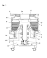
- FIG. 1 is a cross-sectional view showing a schematic configuration of a turbo molecular pump according to the present invention.
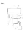
- FIG. 2 is a diagram showing a schematic configuration of a CVD film forming apparatus on which the turbo molecular pump 10 is mounted.
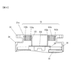
- FIG. 3 is an enlarged view of a portion where the baffle 15 of the turbo molecular pump is provided.
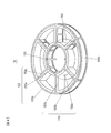
- FIG. 4 is a perspective view of the baffle 15.
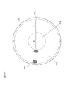
- FIG. 5 is a view showing the baffle 15 as viewed from the intake port side.
- FIGS. 6A and 6B are diagrams for explaining a mesh structure 153 having a laminated structure, in which FIG. 6A is an exploded perspective view of the mesh structure 153, and FIG. FIG.
- FIG. 7 is a diagram illustrating a modification example, where (a) illustrates a first modification example, and (b) illustrates a second modification example.
- 8A and 8B are views showing the mesh structure 153 when the pump casing 34 is cylindrical.
- FIG. 8A shows the case where the mesh structure 153 is provided on the baffle.
- FIG. 8B shows the mesh structure 153 being pumped. The case where it provides in the inner peripheral surface of the casing 34 is shown.
- FIG. 9 is a diagram illustrating a second embodiment.
- FIG. 10 is a plan view of the protective net 101.
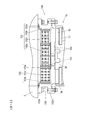
- FIG. 11 is a diagram showing a configuration of the particle trap unit 100 when the protective net 101 is provided on the turbo molecular pump side of the casing 102.
- FIG. 12 is a view showing a modification of the particle trap unit 100.
- FIG. 13 is a diagram illustrating a modified example of the frame 152 and the mesh structure 153.
- FIG. 1 is a sectional view showing a schematic configuration of a turbo molecular pump according to the present invention.
- a rotor 30 is rotatably provided in the pump casing 34.
- the turbo-molecular pump 10 shown in FIG. 1 is a magnetic bearing type pump, and the rotor 30 is supported in a non-contact manner by electromagnets 37 and 38 constituting a 5-axis magnetic bearing.
- the rotor 30 magnetically levitated by the magnetic bearing is driven to rotate at high speed by the motor 36.
- the rotor 30 is formed with a plurality of stages of rotating blades 32 and a cylindrical screw rotor 31.
- a fixed stage is provided with a plurality of stages of fixed blades 33 arranged alternately with the rotary blades 32 in the axial direction, and a screw stator 39 provided on the outer peripheral side of the screw rotor 31.
- Each fixed wing 33 is placed on the base 40 via the spacer ring 35.
- the base 40 is provided with an exhaust port 41, and a back pump is connected to the exhaust port 41.
- a back pump is connected to the exhaust port 41.
- FIG. 2 is a diagram showing an example of the semiconductor manufacturing apparatus 1 on which the turbo molecular pump 10 is mounted, and shows a schematic configuration of the CVD film forming apparatus.
- a turbo molecular pump 10 is attached to the exhaust port 4 provided in the lower part of the process chamber 2 via a gate valve 5.
- Process gas is supplied to the process chamber 2 by a gas supply unit 6.
- the turbo molecular pump 10 includes a mechanism for capturing particles flowing from the air inlet 21a before entering the rotor 30, and a rotor.
- a baffle 15 having a mechanism for capturing recoil particles bounced off at 30 was provided in the pump casing 34.
- FIG. 3 and 4 are diagrams illustrating the baffle 15.
- FIG. 3 is an enlarged view of a portion where the baffle 15 of FIG. 1 is provided.
- FIG. 4 is a perspective view of the baffle 15.
- the baffle 15 is attached to the flange 21 of the pump casing 34.
- the baffle 15 includes a disk 150, support columns 151, a frame 152, and a mesh structure 153.
- the frame 152 has a rib structure, and includes an inner ring 152a, an outer ring 152b, and radial ribs 152c that connect the rings 152a and 152b.
- the plurality of struts 151 are fixed to the inner peripheral surface of the inner ring 152a at equal intervals, and a disk 150 is fixed to the lower end of each strut 151.
- the length of the support column 151 is set so that the disk 150 is disposed in the vicinity of the upper surface of the rotor 30 as shown in FIG.
- the rotor 30 is magnetically levitated and rotates at high speed, but slightly moves up and down in the axial direction according to the gas load. Therefore, the disk 150 is disposed at a position that does not contact the rotor 30 even when the rotor 30 moves up and down.
- the outer diameter dimension of the disk 150 is set to be equal to or smaller than the diameter dimension of the root portion of the rotary blade 32 so that the disk 150 does not block the upper side of the rotary blade 32.
- the plate-like mesh structure 153 is provided so as to cover the outer peripheral surface of the inner ring 152a, the inner peripheral surface of the outer ring 152b, and one surface of the radial ribs 152c, as indicated by reference numerals 153a to 153c.
- the arrangement of the mesh structure 153c shown in FIG. 4 is applied when the rotor 30 is configured to rotate clockwise as viewed from the intake port side. In the case where the rotor 30 is configured to rotate counterclockwise, the mesh structure 153c is preferably attached so that the opposite surface of the radial rib 152c is covered.
- FIG. 5 shows the baffle 15 viewed from the inlet side.
- a broken line indicates the first-stage rotary blade 32 of the rotor 30. Particles that fall into the pump from the air inlet 21 a and pass through the baffle 15 fall on the disk 150 at the center or on the rotor blades 32 on the outer peripheral side of the disk 150. The particles that have fallen on the disk 150 remain on the disk and therefore do not return to the apparatus side.
- FIG. 5 shows some trajectories P when the particles are simply bounced off in the tangential direction.
- the mesh structure 153 is formed by braiding fine wires such as metal wires as will be described later, and the size of the mesh is larger than the size of the particles. Therefore, a part of the recoil particles incident on the mesh structure 153 is bounced back to the surface portion of the wire, but most of the recoil particles enter the inside of the structure and repeatedly collide with the wire inside. By repeating the collision, the kinetic energy of the recoil particles is reduced, and finally, it is captured inside the mesh structure 153.
- FIG. 6A shows an example of the mesh structure 153.
- a cloth-like net 155 constituting a mesh spring described in JP-A-2006-132741 is used.
- the net 155 is formed by knit knitting a fine metal wire such as a stainless steel wire with a knitting machine. It is also possible to use a knitted net sandwiched between molding rollers and a corrugated net as the net 155. Instead of the fine metal wire net, it is also possible to use a woven alumina silica fiber made of alumina and silica. In that case, in order to obtain an appropriate flexibility, the ratio of silica is preferably 6 to 10%. Further, the method of knitting the fine metal wire is not limited to knitting, and plain weaving may be used.
- the mesh structure 153 of the present embodiment is composed of a net 155 formed by braiding a metal wire or the like, the gap is larger than that of a conventional capturing member in which metal fibers are felt. For this reason, the recoil particles easily penetrate into the mesh structure 153 and are reliably captured.
- the structure in which the nets 155 with coarse meshes are stacked makes it easy for recoil particles to enter the mesh structure 153 more inside.
- the same mesh may be laminated, and the one close to the surface is made coarse, and the mesh is made finer so that the inner mesh where particles are trapped is slightly finer. It may be changed accordingly.
- a relatively flat net such as a metal mesh is laminated, it is preferable that the metal mesh is wave-folded and then laminated to increase the bulk so that recoil particles can easily enter the interior.
- the disk 150 is provided in order to prevent particles from splashing on the upper surface (non-rotating blade portion) of the rotor 30.
- the disk 150 since the disk 150 is disposed in the vicinity of the upper surface of the rotor 30, there is almost no difference in conductance depending on the presence or absence of the disk 150, and a reduction in exhaust speed due to the provision of the disk 150 can be prevented.
- the plate-like mesh structure 153 is provided perpendicular to the flange surface so that the surface faces right sideways, the aperture ratio when viewed from the intake port 21a can be maximized, and the exhaust speed can be increased. The decrease can be suppressed. That is, the baffle 15 in the present embodiment can reliably capture the recoil particles while suppressing the decrease in the exhaust speed as much as possible.
- FIG. 7 is a diagram showing a modification of the present embodiment.
- a decrease in conductance due to the baffle 15 is made smaller, and the exhaust speed is more important. Therefore, the inner ring 152a and the radial ribs 152c shown in FIG. 4 and the mesh structures 153a and 153c provided on them are omitted.
- a plurality of support beams 152d are provided radially from the outer ring 152b, and the columns 151 are fixed to the support beams 152d.
- a mesh structure 153d is provided directly on the inner peripheral surface of the pump casing 34 in place of the outer ring 152b and the mesh structure 153b shown in FIG. 7A. In this case as well, a decrease in exhaust speed can be suppressed as much as possible.
- FIG. 8 shows a case where the pump casing 34 is applied to a cylindrical pump.
- FIG. 8A corresponds to FIG. 3
- FIG. 8B corresponds to FIG. 7B.
- a disk 150 and a mesh structure 153e arranged on the inner peripheral surface of the pump casing are provided.
- the outer ring 152b and the mesh structure 153b are provided. The structure is almost the same as that of the case of providing.
- the frame 152 of the baffle 15 has a rib structure, but the rib structure may not be used. Further, the thermal emissivity of the surface of the disk 150 may be reduced to reduce the influence of thermal radiation between the process chamber and the rotor 30.
- FIG. 9 is a diagram showing a second embodiment of the present invention.
- the baffle 15 for capturing particles is provided in the pump casing 34 of the turbo molecular pump.
- the baffle 15 as described above can be mounted in the pump casing. Therefore, in a second embodiment described below, a particle trap unit that can be additionally mounted later even if it is a turbo molecular pump having a configuration in which the baffle 15 cannot be mounted in the pump casing will be described.
- FIG. 9 shows the particle trap unit 100 attached to the turbo molecular pump.
- the particle trap unit 100 includes a frame 152, a mesh structure 153, a casing 102, and a protective net 101.
- the frame 152 and the mesh structure 153 are the same as the frame 152 and the mesh structure 153 of the baffle 15 shown in FIG. That is, the particle trap unit 100 captures the recoil particles bounced off by the rotor 30 and prevents the recoil particles from flowing back from the turbo molecular pump side to the apparatus side.
- the frame 152 is fixed to the casing 102 by fastening the fixing portion 152b to the casing 102 with a screw 105.
- the mesh structure 153 is attached to the frame 152.
- the casing 102 includes a flange 102a fixed to the flange 21 of the turbo molecular pump 10 and a flange 102b fixed to the apparatus side.
- the apparatus-side flange 102 b is connected to the gate valve 5.
- the flange 102 b is connected to the process chamber 2. That is, the particle trap unit 100 is provided so as to be interposed between the turbo molecular pump 10 and the apparatus side.
- a sealing material (O-ring) 106 is attached to the flange 102b.
- the sealing material (O-ring) 21 b is attached to the flange 21 of the turbo molecular pump 10.
- the flange 102a and the flange 21 are fastened by the bolt 103, the gap between the flange 102a and the flange 21 is sealed by the sealing material 21b.
- FIG. 10 is a plan view of the protective net 101.
- the protective net 101 is formed of a thin plate such as a stainless material.
- the protective net 101 has a circular area 101a indicated by reference numeral A and an annular net area 101b indicated by reference numeral B.
- a plurality of openings 101d are formed in the net region 101b by etching. In the example shown in FIG. 10, regular hexagonal openings 101d are formed in a honeycomb shape.
- the circular region 101a is formed by performing circular masking during etching.
- a screw hole 101 c is formed in the peripheral portion of the protective net 101.
- the protective net 101 is fixed to the ring portion 210 of the flange 21 of the turbo molecular pump 10 by screws 107, but the gap between the flange 102 a of the casing 102 and the ring portion 210.
- screws may be fixed to the flange 102 a on the turbo molecular pump side of the casing 102 or may be directly fixed to the frame 152.
- the diameter of the circular area 101a of the protective net 101 is set to be equal to or less than the diameter of the root portion of the rotor blade 32 of the rotor 30, and the net area 101b faces the rotor blade 32.
- the turbo molecular pump 10 exhausts the gas that has passed through the net region 101b.
- the net region 101b is provided in order to prevent foreign matter (wafer fragments, a part of apparatus side parts, etc.) from falling into the turbo molecular pump and damaging the rotary blade 32 and the fixed blade 33.
- the circular area 101 a of the protective net 101 functions in the same manner as the disk 150 described above, and prevents particles from the apparatus side from falling on the upper surface of the rotor 30.
- the circular region 101a is formed by performing circular masking when etching the thin plate material. However, after the whole is etched into a net shape, the disk is attached to the center portion. Therefore. Further, when a net woven with metal wires is used as the protective net 101, the protective net 101 is formed by attaching a disk to the central portion.
- the particle trap unit 100 includes the protective net 101.
- the particle trap unit 100 may be constituted by components other than the protection net 101.
- FIG. 12 is a view showing a modified example of the particle trap unit 100.
- a disk 150 shown in FIG. 4 is provided in place of the protective net 101 shown in FIG.
- the disk 150 is fixed to the inner ring 152 a by a column 151.
- the position of the disk 150 in the axial direction may be within the casing 102 as indicated by the solid line, or the support column 151 is extended to the pump side as indicated by the two-dot chain line, and the disk 150 is disposed near the upper portion of the rotor 30. You may be made to do.
- FIG. 13 shows a modified example of the frame 152 and the mesh structure 153 arranged in the casing 102.
- the frame 152 is also provided with radial ribs 152e inside the inner ring 152a.
- the mesh structures 153f and 153g were attached to the inner peripheral surface side of the inner ring 152a and the radial ribs 152e.
- an opening 101d is also formed in the area indicated by reference numeral A.
- the exhaust efficiency with respect to gas molecules incident on the inner side of the inner ring 152a can be improved, and a decrease in exhaust speed can be suppressed.
- the particle trap unit 100 As shown in the second embodiment, it is possible to take measures against recoil particles without replacing the pump even if the turbo molecular pump is not provided with measures against recoil particles. Can do. Further, by integrally forming a disc for preventing particles from falling onto the upper surface of the rotor on the protective net for preventing foreign matter from entering, it is possible to suppress an increase in the number of parts and suppress an increase in cost.
- the protective net 101 shown in FIG. 10 can be used instead of the disk 150.
Landscapes
- Engineering & Computer Science (AREA)
- Mechanical Engineering (AREA)
- General Engineering & Computer Science (AREA)
- Non-Positive Displacement Air Blowers (AREA)
Abstract
Description
なお、円筒状の網目構造体に対して放射状に配置され、ポンプ吸気口に対して垂直な板状の網目構造体を複数備えるようにしても良い。
本発明によるターボ分子ポンプの第2の態様は、多段の回転翼が形成され、高速回転するロータと、回転翼に対してポンプ軸方向に交互に配置された複数の固定翼と、回転翼および固定翼を収容し、吸気口が形成されたポンプハウジングと、ロータの吸気口側に近接して設けられ、ロータの回転翼根元よりも内径側の面に対向するように配置される円盤と、ポンプハウジングの内壁に沿って設けられ、細線を編み上げて形成された網目構造体とを備える。
なお、円盤と、該円盤を囲むように設けられるとともに複数の開口が形成されたネット領域とを有して、前記吸気口を介した前記ポンプハウジング内への異物の侵入を防止する保護ネットを備えるようにしても良い。
また、網目構造体を、細線を編み上げて形成された布状のネットを層状に配置したもので構成しても良い。
さらに、細線は、ステンレス細線で構成されていても良いし、シリカの比率が6~10%のアルミナシリカ繊維で構成されていても良い。
本発明によるターボ分子ポンプの第3の態様は、ターボ分子ポンプの吸気口フランジに接続される第1のフランジ、および真空装置側の排気口フランジに接続される第2のフランジを備えるケーシングと、ケーシング内に配置され、ターボ分子ポンプのロータにより跳ね飛ばされたパーティクルを内部に捕捉するように細線を編み上げて形成された円筒状の網目構造体と、を備える。
なお、ターボ分子ポンプのロータ上面に対向するように第1のフランジ側に配置され、直径寸法がターボ分子ポンプのロータの回転翼根元の直径以下である円盤を備えるようにしても良い。
また、直径寸法がターボ分子ポンプのロータの回転翼根元の直径以下である円形領域と、該円形領域の周囲を囲むように設けられるとともに複数の開口が形成されたネット領域とを有して、吸気口フランジを介したターボ分子ポンプ内への異物の侵入を防止する保護ネットを備えるようにしても良い。
さらに、円筒状の網目構造体に対して放射状に配置され、第1および第2のフランジの軸方向に沿った板状の網目構造体を複数備えるようにしても良い。
また、細線はステンレス細線で構成されていても良いし、シリカの比率が6~10%のアルミナシリカ繊維で構成されていても良い。
-第1の実施の形態-
図1は本発明によるターボ分子ポンプの概略構成を示す断面図である。ポンプケーシング34内にはロータ30が回転自在に設けられている。図1に示したターボ分子ポンプ10は磁気軸受式のポンプであり、ロータ30は、5軸磁気軸受を構成する電磁石37,38によって非接触支持される。磁気軸受によって磁気浮上されたロータ30は、モータ36により高速回転駆動される。
図9は、本発明の第2の実施の形態を示す図である。上述した第1の実施の形態では、パーティクル補足用のバッフル15をターボ分子ポンプのポンプケーシング34内に設けた。しかしながら、全てのターボ分子ポンプが、上述したようなバッフル15をポンプケーシング内に取り付けられるような構成となっているとは限らない。そこで、以下に説明する第2の実施の形態では、バッフル15をポンプケーシング内に取り付けられない構成のターボ分子ポンプであっても、後から付加的に装着できるパーティクルトラップユニットについて説明する。
日本国特許出願2009年第41318号(2009年2月24日出願)
日本国特許出願2009年第251801号(2009年11月2日出願)
Claims (13)
- 多段の回転翼が形成され、高速回転するロータと、
前記回転翼に対してポンプ軸方向に交互に配置された複数の固定翼と、
前記回転翼および固定翼を収容し、吸気口が形成されたポンプハウジングと、
前記ロータの吸気口側に近接して設けられ、前記ロータの回転翼根元よりも内径側の面に対向するように配置される円盤と、
前記吸気口と前記ロータとの間に配置され、細線を編み上げて形成された円筒状の網目構造体とを備え、
前記ロータにより跳ね飛ばされたパーティクルを、前記網目構造体の内部に捕捉するターボ分子ポンプ。 - 請求項1に記載のターボ分子ポンプにおいて、
前記円筒状の網目構造体に対して放射状に配置され、ポンプ吸気口に対して垂直な板状の網目構造体を複数備える。 - 多段の回転翼が形成され、高速回転するロータと、
前記回転翼に対してポンプ軸方向に交互に配置された複数の固定翼と、
前記回転翼および固定翼を収容し、吸気口が形成されたポンプハウジングと、
前記ロータの吸気口側に近接して設けられ、前記ロータの回転翼根元よりも内径側の面に対向するように配置される円盤と、
前記ポンプハウジングの内壁に沿って設けられ、細線を編み上げて形成された網目構造体とを備えたターボ分子ポンプ。 - 請求項1~3のいずれか一項に記載のターボ分子ポンプにおいて、
前記円盤と、該円盤を囲むように設けられるとともに複数の開口が形成されたネット領域とを有して、前記吸気口を介した前記ポンプハウジング内への異物の侵入を防止する保護ネットを備える。 - 請求項1~4のいずれか一項に記載のターボ分子ポンプにおいて、
前記網目構造体は、細線を編み上げて形成された布状のネットを層状に配置したものである。 - 請求項1~5のいずれか一項に記載のターボ分子ポンプにおいて、
前記細線はステンレス細線で構成されている。 - 請求項1~5のいずれか一項に記載のターボ分子ポンプにおいて、
前記細線は、シリカの比率が6~10%のアルミナシリカ繊維で構成されている。 - ターボ分子ポンプの吸気口フランジに接続される第1のフランジ、および真空装置側の排気口フランジに接続される第2のフランジを備えるケーシングと、
前記ケーシング内に配置され、前記ターボ分子ポンプのロータにより跳ね飛ばされたパーティクルを内部に捕捉するように細線を編み上げて形成された円筒状の網目構造体と、を備えたターボ分子ポンプ用パーティクルトラップ。 - 請求項8に記載のターボ分子ポンプ用パーティクルトラップにおいて、
前記ターボ分子ポンプのロータ上面に対向するように前記第1のフランジ側に配置され、直径寸法が前記ターボ分子ポンプのロータの回転翼根元の直径以下である円盤を備える。 - 請求項8に記載のターボ分子ポンプ用パーティクルトラップにおいて、
直径寸法が前記ターボ分子ポンプのロータの回転翼根元の直径以下である円形領域と、該円形領域の周囲を囲むように設けられるとともに複数の開口が形成されたネット領域とを有して、前記吸気口フランジを介したターボ分子ポンプ内への異物の侵入を防止する保護ネットを備える。 - 請求項8~10のいずれか一項に記載のターボ分子ポンプ用パーティクルトラップにおいて、
前記円筒状の網目構造体に対して放射状に配置され、前記第1および第2のフランジの軸方向に沿った板状の網目構造体を複数備える。 - 請求項8~11のいずれか一項に記載のターボ分子ポンプ用パーティクルトラップにおいて、
前記細線はステンレス細線で構成されている。 - 請求項8~11のいずれか一項に記載のターボ分子ポンプ用パーティクルトラップにおいて、
前記細線は、シリカの比率が6~10%のアルミナシリカ繊維で構成されている。
Priority Applications (3)
| Application Number | Priority Date | Filing Date | Title |
|---|---|---|---|
| KR1020117018647A KR101342306B1 (ko) | 2009-02-24 | 2010-02-05 | 터보 분자 펌프 및 터보 분자 펌프용 파티클 트랩 |
| CN201080009031.3A CN102326002B (zh) | 2009-02-24 | 2010-02-05 | 涡轮分子泵及涡轮分子泵用颗粒捕集器 |
| US13/146,497 US8894355B2 (en) | 2009-02-24 | 2010-02-05 | Turbomolecular pump, and particle trap for turbomolecular pump |
Applications Claiming Priority (4)
| Application Number | Priority Date | Filing Date | Title |
|---|---|---|---|
| JP2009041318 | 2009-02-24 | ||
| JP2009-041318 | 2009-02-24 | ||
| JP2009251801A JP5412239B2 (ja) | 2009-02-24 | 2009-11-02 | ターボ分子ポンプおよびターボ分子ポンプ用パーティクルトラップ |
| JP2009-251801 | 2009-11-02 |
Publications (1)
| Publication Number | Publication Date |
|---|---|
| WO2010098192A1 true WO2010098192A1 (ja) | 2010-09-02 |
Family
ID=42665402
Family Applications (1)
| Application Number | Title | Priority Date | Filing Date |
|---|---|---|---|
| PCT/JP2010/051686 Ceased WO2010098192A1 (ja) | 2009-02-24 | 2010-02-05 | ターボ分子ポンプおよびターボ分子ポンプ用パーティクルトラップ |
Country Status (6)
| Country | Link |
|---|---|
| US (1) | US8894355B2 (ja) |
| JP (1) | JP5412239B2 (ja) |
| KR (1) | KR101342306B1 (ja) |
| CN (1) | CN102326002B (ja) |
| TW (1) | TWI385307B (ja) |
| WO (1) | WO2010098192A1 (ja) |
Families Citing this family (12)
| Publication number | Priority date | Publication date | Assignee | Title |
|---|---|---|---|---|
| JP5460982B2 (ja) * | 2008-07-30 | 2014-04-02 | 東京エレクトロン株式会社 | 弁体、粒子進入阻止機構、排気制御装置及び基板処理装置 |
| JP5865596B2 (ja) * | 2011-03-25 | 2016-02-17 | 東京エレクトロン株式会社 | 粒子捕捉ユニット、該粒子捕捉ユニットの製造方法及び基板処理装置 |
| JP5944883B2 (ja) * | 2013-12-18 | 2016-07-05 | 東京エレクトロン株式会社 | 粒子逆流防止部材及び基板処理装置 |
| US10107151B2 (en) | 2013-12-25 | 2018-10-23 | Aisin Seiki Kabushiki Kaisha | Control valve |
| JP6353257B2 (ja) * | 2014-03-31 | 2018-07-04 | エドワーズ株式会社 | 排気口部品、および真空ポンプ |
| CN105879540A (zh) * | 2014-12-16 | 2016-08-24 | 时剑 | 一种离心式空气净化器 |
| JP6014215B2 (ja) * | 2015-08-26 | 2016-10-25 | 東京エレクトロン株式会社 | 粒子捕捉ユニット、該粒子捕捉ユニットの製造方法及び基板処理装置 |
| CN106611693B (zh) * | 2015-10-27 | 2019-02-19 | 北京北方华创微电子装备有限公司 | 反应腔室及半导体加工设备 |
| JP6706553B2 (ja) * | 2015-12-15 | 2020-06-10 | エドワーズ株式会社 | 真空ポンプ及び該真空ポンプに搭載される回転翼、反射機構 |
| JP6906377B2 (ja) * | 2017-06-23 | 2021-07-21 | 東京エレクトロン株式会社 | 排気プレート及びプラズマ処理装置 |
| JP6885851B2 (ja) | 2017-10-27 | 2021-06-16 | エドワーズ株式会社 | 真空ポンプ、ロータ、ロータフィン、およびケーシング |
| JP7327229B2 (ja) * | 2020-03-18 | 2023-08-16 | 株式会社島津製作所 | 保護ネット、ターボ分子ポンプおよび質量分析装置 |
Citations (2)
| Publication number | Priority date | Publication date | Assignee | Title |
|---|---|---|---|---|
| JP2005344512A (ja) * | 2004-05-31 | 2005-12-15 | Osaka Vacuum Ltd | 分子ポンプ |
| JP2008240701A (ja) * | 2007-03-28 | 2008-10-09 | Tokyo Electron Ltd | 排気ポンプ、連通管及び排気システム |
Family Cites Families (13)
| Publication number | Priority date | Publication date | Assignee | Title |
|---|---|---|---|---|
| CN1012518B (zh) * | 1988-07-12 | 1991-05-01 | 中国科学院北京真空物理实验室 | 复合式分子泵 |
| WO1994007033A1 (en) * | 1992-09-23 | 1994-03-31 | United States Of America As Represented By The Secretary Of The Air Force | Turbo-molecular blower |
| US20030017047A1 (en) * | 1998-06-25 | 2003-01-23 | Ebara Corporation | Turbo-molecular pump |
| JP3812635B2 (ja) | 1999-06-14 | 2006-08-23 | 株式会社荏原製作所 | ターボ分子ポンプ |
| KR20010007349A (ko) | 1999-06-14 | 2001-01-26 | 마에다 시게루 | 터보분자펌프 |
| TW475034B (en) | 1999-10-28 | 2002-02-01 | Mosel Vitelic Inc | Evacuation device |
| JP2004278500A (ja) | 2003-03-19 | 2004-10-07 | Boc Edwards Kk | 分子ポンプ |
| JP2007180467A (ja) | 2005-03-02 | 2007-07-12 | Tokyo Electron Ltd | 反射装置、連通管、排気ポンプ、排気システム、該システムの洗浄方法、記憶媒体、基板処理装置及びパーティクル捕捉部品 |
| US7927066B2 (en) * | 2005-03-02 | 2011-04-19 | Tokyo Electron Limited | Reflecting device, communicating pipe, exhausting pump, exhaust system, method for cleaning the system, storage medium storing program for implementing the method, substrate processing apparatus, and particle capturing component |
| JP2006307823A (ja) * | 2005-03-31 | 2006-11-09 | Shimadzu Corp | ターボ分子ポンプ |
| JP4760424B2 (ja) * | 2006-02-09 | 2011-08-31 | 株式会社島津製作所 | ターボ分子ポンプ |
| JP5050369B2 (ja) | 2006-03-06 | 2012-10-17 | 東京エレクトロン株式会社 | 処理装置 |
| DE102007048703A1 (de) | 2007-10-11 | 2009-04-16 | Oerlikon Leybold Vacuum Gmbh | Mehrstufiger Turbomolekularpumpen-Pumpenrotor |
-
2009
- 2009-11-02 JP JP2009251801A patent/JP5412239B2/ja active Active
-
2010
- 2010-02-05 US US13/146,497 patent/US8894355B2/en active Active
- 2010-02-05 KR KR1020117018647A patent/KR101342306B1/ko active Active
- 2010-02-05 CN CN201080009031.3A patent/CN102326002B/zh active Active
- 2010-02-05 WO PCT/JP2010/051686 patent/WO2010098192A1/ja not_active Ceased
- 2010-02-10 TW TW099104100A patent/TWI385307B/zh active
Patent Citations (2)
| Publication number | Priority date | Publication date | Assignee | Title |
|---|---|---|---|---|
| JP2005344512A (ja) * | 2004-05-31 | 2005-12-15 | Osaka Vacuum Ltd | 分子ポンプ |
| JP2008240701A (ja) * | 2007-03-28 | 2008-10-09 | Tokyo Electron Ltd | 排気ポンプ、連通管及び排気システム |
Also Published As
| Publication number | Publication date |
|---|---|
| JP2010223213A (ja) | 2010-10-07 |
| KR101342306B1 (ko) | 2013-12-16 |
| KR20110104554A (ko) | 2011-09-22 |
| US20110293401A1 (en) | 2011-12-01 |
| CN102326002B (zh) | 2014-05-07 |
| CN102326002A (zh) | 2012-01-18 |
| JP5412239B2 (ja) | 2014-02-12 |
| TWI385307B (zh) | 2013-02-11 |
| TW201033470A (en) | 2010-09-16 |
| US8894355B2 (en) | 2014-11-25 |
Similar Documents
| Publication | Publication Date | Title |
|---|---|---|
| JP5412239B2 (ja) | ターボ分子ポンプおよびターボ分子ポンプ用パーティクルトラップ | |
| JP5350598B2 (ja) | 排気ポンプ、連通管、排気システム及び基板処理装置 | |
| KR101356829B1 (ko) | 입자포착 유닛, 해당 입자포착 유닛의 제조 방법 및 기판 처리 장치 | |
| US10024327B2 (en) | Turbomolecular pump, and method of manufacturing rotor | |
| JP6691487B2 (ja) | ターボ機械用のシールデバイス | |
| JP6084119B2 (ja) | クライオポンプ | |
| JP6053588B2 (ja) | クライオポンプ、及び非凝縮性気体の真空排気方法 | |
| JPWO2014049728A1 (ja) | 真空ポンプ用保護ネット、その製造方法および真空ポンプ | |
| JP2017110627A (ja) | 真空ポンプ及び該真空ポンプに搭載される回転翼、反射機構 | |
| US20080286089A1 (en) | Turbo-molecular pump | |
| JP7419976B2 (ja) | 真空バルブ、ターボ分子ポンプおよび真空容器 | |
| US8459931B2 (en) | Turbo-molecular pump | |
| JP2007046461A (ja) | ターボ分子ポンプ | |
| WO2014041995A1 (ja) | 真空ポンプのロータ及び真空ポンプ | |
| JP2008144630A (ja) | 真空ポンプ、真空容器および配管構造体 | |
| JP5434684B2 (ja) | ターボ分子ポンプ | |
| JP6014215B2 (ja) | 粒子捕捉ユニット、該粒子捕捉ユニットの製造方法及び基板処理装置 | |
| JP3120167U (ja) | ターボ分子ポンプ | |
| JP4760424B2 (ja) | ターボ分子ポンプ | |
| JP3099516B2 (ja) | 真空ポンプ | |
| JP4716109B2 (ja) | ターボ分子ポンプ | |
| JP2004116354A (ja) | ターボ分子ポンプ |
Legal Events
| Date | Code | Title | Description |
|---|---|---|---|
| WWE | Wipo information: entry into national phase |
Ref document number: 201080009031.3 Country of ref document: CN |
|
| 121 | Ep: the epo has been informed by wipo that ep was designated in this application |
Ref document number: 10746073 Country of ref document: EP Kind code of ref document: A1 |
|
| WWE | Wipo information: entry into national phase |
Ref document number: 13146497 Country of ref document: US |
|
| ENP | Entry into the national phase |
Ref document number: 20117018647 Country of ref document: KR Kind code of ref document: A |
|
| NENP | Non-entry into the national phase |
Ref country code: DE |
|
| 122 | Ep: pct application non-entry in european phase |
Ref document number: 10746073 Country of ref document: EP Kind code of ref document: A1 |