WO2010097907A1 - パッケージの製造方法、並びにパッケージ、圧電振動子、発振器、電子機器及び電波時計 - Google Patents
パッケージの製造方法、並びにパッケージ、圧電振動子、発振器、電子機器及び電波時計 Download PDFInfo
- Publication number
- WO2010097907A1 WO2010097907A1 PCT/JP2009/053336 JP2009053336W WO2010097907A1 WO 2010097907 A1 WO2010097907 A1 WO 2010097907A1 JP 2009053336 W JP2009053336 W JP 2009053336W WO 2010097907 A1 WO2010097907 A1 WO 2010097907A1
- Authority
- WO
- WIPO (PCT)
- Prior art keywords
- glass frit
- base substrate
- package
- manufacturing
- hole
- Prior art date
- Legal status (The legal status is an assumption and is not a legal conclusion. Google has not performed a legal analysis and makes no representation as to the accuracy of the status listed.)
- Ceased
Links
Images


















Classifications
-
- H—ELECTRICITY
- H03—ELECTRONIC CIRCUITRY
- H03H—IMPEDANCE NETWORKS, e.g. RESONANT CIRCUITS; RESONATORS
- H03H9/00—Networks comprising electromechanical or electro-acoustic elements; Electromechanical resonators
- H03H9/15—Constructional features of resonators consisting of piezoelectric or electrostrictive material
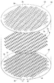
- H03H9/21—Crystal tuning forks
- H03H9/215—Crystal tuning forks consisting of quartz
-
- H—ELECTRICITY
- H03—ELECTRONIC CIRCUITRY
- H03H—IMPEDANCE NETWORKS, e.g. RESONANT CIRCUITS; RESONATORS
- H03H3/00—Apparatus or processes specially adapted for the manufacture of impedance networks, resonating circuits, resonators
- H03H3/007—Apparatus or processes specially adapted for the manufacture of impedance networks, resonating circuits, resonators for the manufacture of electromechanical resonators or networks
- H03H3/02—Apparatus or processes specially adapted for the manufacture of impedance networks, resonating circuits, resonators for the manufacture of electromechanical resonators or networks for the manufacture of piezoelectric or electrostrictive resonators or networks
-
- H—ELECTRICITY
- H03—ELECTRONIC CIRCUITRY
- H03H—IMPEDANCE NETWORKS, e.g. RESONANT CIRCUITS; RESONATORS
- H03H9/00—Networks comprising electromechanical or electro-acoustic elements; Electromechanical resonators
- H03H9/02—Details
- H03H9/05—Holders or supports
- H03H9/10—Mounting in enclosures
- H03H9/1007—Mounting in enclosures for bulk acoustic wave [BAW] devices
- H03H9/1014—Mounting in enclosures for bulk acoustic wave [BAW] devices the enclosure being defined by a frame built on a substrate and a cap, the frame having no mechanical contact with the BAW device
- H03H9/1021—Mounting in enclosures for bulk acoustic wave [BAW] devices the enclosure being defined by a frame built on a substrate and a cap, the frame having no mechanical contact with the BAW device the BAW device being of the cantilever type
-
- H—ELECTRICITY
- H03—ELECTRONIC CIRCUITRY
- H03H—IMPEDANCE NETWORKS, e.g. RESONANT CIRCUITS; RESONATORS
- H03H9/00—Networks comprising electromechanical or electro-acoustic elements; Electromechanical resonators
- H03H9/15—Constructional features of resonators consisting of piezoelectric or electrostrictive material
- H03H9/21—Crystal tuning forks
-
- H—ELECTRICITY
- H03—ELECTRONIC CIRCUITRY
- H03H—IMPEDANCE NETWORKS, e.g. RESONANT CIRCUITS; RESONATORS
- H03H3/00—Apparatus or processes specially adapted for the manufacture of impedance networks, resonating circuits, resonators
- H03H3/007—Apparatus or processes specially adapted for the manufacture of impedance networks, resonating circuits, resonators for the manufacture of electromechanical resonators or networks
- H03H3/02—Apparatus or processes specially adapted for the manufacture of impedance networks, resonating circuits, resonators for the manufacture of electromechanical resonators or networks for the manufacture of piezoelectric or electrostrictive resonators or networks
- H03H2003/022—Apparatus or processes specially adapted for the manufacture of impedance networks, resonating circuits, resonators for the manufacture of electromechanical resonators or networks for the manufacture of piezoelectric or electrostrictive resonators or networks the resonators or networks being of the cantilever type
-
- Y—GENERAL TAGGING OF NEW TECHNOLOGICAL DEVELOPMENTS; GENERAL TAGGING OF CROSS-SECTIONAL TECHNOLOGIES SPANNING OVER SEVERAL SECTIONS OF THE IPC; TECHNICAL SUBJECTS COVERED BY FORMER USPC CROSS-REFERENCE ART COLLECTIONS [XRACs] AND DIGESTS
- Y10—TECHNICAL SUBJECTS COVERED BY FORMER USPC
- Y10T—TECHNICAL SUBJECTS COVERED BY FORMER US CLASSIFICATION
- Y10T29/00—Metal working
- Y10T29/42—Piezoelectric device making
Definitions
- the present invention relates to a manufacturing method of a package having a cavity for hermetically sealing an object to be stored, a package manufactured by the manufacturing method, a piezoelectric vibrator, an oscillator, an electronic device, and a radio timepiece using the package. It is.
- a piezoelectric vibrator using a crystal or the like as a timing source such as a time source or a control signal, a reference signal source, or the like is used in a mobile phone or a portable information terminal device.
- a base substrate (base member), a piezoelectric vibrating piece (quartz vibrator) mounted on the base substrate, and the piezoelectric vibrating piece are hermetically sealed.
- a configuration including a lid substrate (cap member) covered with a base substrate is known.
- the piezoelectric vibrator includes an external electrode (external connection electrode) on one surface of the base substrate, and a routing electrode (crystal connection electrode) on the other surface of the base substrate.
- the piezoelectric vibrating piece is provided on the routing electrode. Is installed. Then, the external electrode and the lead-out electrode are electrically connected by a core member (metal member) penetrating the base substrate.
- Patent Document 1 in order to form the core material portion in manufacturing the piezoelectric vibrator, a small-diameter through hole is formed in the base substrate, and the pin-shaped metal member is attached while the base substrate is in the heat softened state.
- the method of driving is adopted.
- a gap may be formed between the core portion and the through hole, so that it is difficult to ensure airtightness in the cavity formed between the base substrate and the lid substrate. It is. Therefore, when forming the core member, a metal member is disposed in the through hole formed in the base substrate, and a paste-like glass frit is filled between the metal member and the through hole, and the filled glass frit is fired. Then, a method of fixing the through hole, the metal member, and the glass frit integrally can be considered. According to this method, the airtightness in the cavity can be ensured.
- the pin-shaped metal member when forming the core part, is used as described above, but the flat head part and the core part protruding from the back surface of the head part are provided.
- a method in which the housing having the metal member is used instead of the metal member is also conceivable.
- the core material portion can be disposed in the through hole by a simple operation of inserting the core material portion into the through hole until the back surface of the head contacts the surface of the base substrate. Thereafter, when the glass frit is filled in the through hole, the head of the housing acts as a cover for the through hole, and the glass frit can be prevented from leaking to the outside.
- the core member is formed using the casing and the glass frit as described above, generally, after firing the glass frit, the head of the casing is polished (ground) and removed. As a result, the base substrate, the glass frit, and the core member can be flush with each other, and each electrode (leading electrode and external electrode) can be reliably formed on the base substrate.
- the binder contained in the glass frit burns to generate gas inside the glass frit. This gas escapes to the outside through the part where the glass frit is exposed to the outside.
- the head of the housing acts as a lid for the through hole. In some cases, bubbles may be formed between the housing head and the glass frit without escaping. In this case, when the head portion of the housing is removed after firing the glass frit, a recess remains on the surface of the glass frit.
- each electrode when the electrodes and external electrodes are formed on the base substrate with the recesses remaining in the glass frit, it is difficult to form each electrode with a uniform thickness, and an electrode with a very small thickness is formed. Sometimes. In this case, the thinly formed portion of each electrode may be locally disconnected due to deterioration over time, and there is a possibility that the continuity between the piezoelectric vibrating piece and the external electrode is impaired. Further, even if the head of the casing is not removed after the glass frit firing, there is a risk that cracks or cracks may occur starting from the bubbles formed inside the glass frit.
- the present invention has been made in view of such circumstances, and its purpose is to produce a high-quality package in which the formation of bubbles in the glass frit is suppressed while ensuring airtightness in the cavity. Is to provide.
- Another object of the present invention is to provide a package manufactured by this manufacturing method, a piezoelectric vibrator, an oscillator, an electronic device, and a radio timepiece using the package.
- a method of manufacturing a package according to the present invention includes: a plurality of substrates that are adjacent to each other in a stacked state; and a substrate to be stored between a pair of substrates among the plurality of substrates.
- a package comprising: a material portion; and a glass frit that is filled and fired between the through hole and the core material portion and seals between the two, a flat head, and a back surface of the head
- a gas escape passage that communicates from the base end of the core part to the side surface or the surface of the head is formed on the back surface of the head.
- the gas escape passage is formed on the back surface of the top of the housing, the periphery of the base end of the core portion in the paste-like glass frit filled in the glass frit filling step The portion located at the side is exposed to the outside from the side surface or the surface of the head through the gas escape passage. Therefore, in the firing step, the gas generated inside the glass frit due to the burning of the binder contained in the glass frit can be discharged outside through the gas escape passage. As a result, it is possible to suppress the formation of bubbles between the head of the housing and the glass frit, and it is possible to manufacture a high-quality package in which the formation of bubbles inside the glass frit is suppressed. it can.
- the glass frit filling step includes the laminating material pasting step of pasting the laminating material on the first surface so as to cover the head of the housing disposed on the base substrate before the glass frit filling step. Therefore, it is possible to reliably prevent the paste-like glass frit from flowing through the gas escape passage and leaking to the outside.
- the base substrate and the casing can be held by the laminate material, and the casing can be reliably prevented from falling off the base substrate.
- the laminate material has elasticity, it is possible to reduce the load on the part where the base substrate and the casing are in contact with each other in the glass frit filling process, and to suppress the base substrate from cracking. can do. As described above, it is possible to suppress the occurrence of bubbles inside the glass frit and the occurrence of cracks in the base substrate while suppressing the formation of air bubbles inside the glass frit, thereby improving the yield of package manufacturing. be able to.
- the laminate material includes: a tape main body having elasticity; and a thermoplastic adhesive material applied to the tape main body.
- the filled glass frit is removed from the baking process.
- the laminating material peeling step is performed before the firing step, the firing step is performed in a state where the laminate material is peeled off. Therefore, when the glass frit is heated to a high temperature at which the glass frit is fired in the firing process, for example, the tape body does not burn and affect the quality of the package. Can be manufactured.
- a polishing step may be provided in which the first surface side of the base substrate is polished to remove the head portion and the core material portion is exposed on the first surface of the base substrate.
- the package which concerns on this invention is manufactured by the manufacturing method of the package of any one of said (1) to (4).
- the package is manufactured by the method for manufacturing a package according to the present invention, it is excellent in airtightness and high quality.
- the package according to the present invention is formed by sandwiching a plurality of substrates adjacent to each other in a stacked state; and sandwiched between a pair of substrates among the plurality of substrates.
- a flat plate portion connected to the core portion and disposed in the cavity; a glass frit filled between the through hole and the core portion and baked to seal between the two The flat plate portion is disposed in the cavity so as to cover the through hole; and the glass frit is exposed in the cavity.
- the flat plate portion is disposed in the cavity so as to cover the through hole, while the glass frit is exposed in the cavity. Accordingly, when the package is manufactured, after the paste-like glass frit is filled between the core portion and the through hole, the binder contained in the glass frit is heated when the filled glass frit is heated for firing. The gas generated inside the glass frit by burning can escape from the portion of the glass frit exposed in the cavity. As a result, it is possible to suppress the formation of bubbles between the flat plate portion and the glass frit, and it is possible to obtain a high quality package in which the formation of bubbles inside the glass frit is suppressed.
- a piezoelectric vibrator according to the present invention includes the package according to the above (5) or (6); and a piezoelectric vibrating piece accommodated as the object to be stored in the cavity.
- the piezoelectric vibrating piece is accommodated in a cavity having excellent airtightness, the piezoelectric vibrating piece is hardly affected by dust or the like and operates with high accuracy. Furthermore, a package is used in which the formation of bubbles inside the glass frit is suppressed and the quality is improved. From the above, a piezoelectric vibrator with improved quality can be obtained.
- the piezoelectric vibrator described in (7) is electrically connected to an integrated circuit as an oscillator.
- the piezoelectric vibrator described in the above (7) is electrically connected to the time measuring unit.
- the piezoelectric vibrator described in (7) is electrically connected to the filter unit.
- the piezoelectric vibrator described above since the piezoelectric vibrator described above is provided, high quality can be achieved in the same manner.
- the package manufacturing method of the present invention it is possible to manufacture a high-quality package in which the formation of bubbles inside the glass frit is suppressed while ensuring airtightness in the cavity.
- the airtightness is excellent and the quality is improved.
- the piezoelectric vibrator since the package is provided, the quality can be similarly improved.
- FIG. 1 is an external perspective view showing the piezoelectric vibrator of the first embodiment according to the present invention.
- FIG. 2 is an internal configuration diagram of the piezoelectric vibrator shown in FIG. 1 and is a view of the piezoelectric vibrating piece viewed from above with the lid substrate removed.
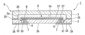
- 3 is a cross-sectional view taken along line AA shown in FIG.
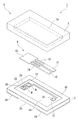
- FIG. 4 is an exploded perspective view of the piezoelectric vibrator shown in FIG.
- FIG. 5 is a top view of the piezoelectric vibrating piece constituting the piezoelectric vibrator shown in FIG. 6 is a bottom view of the piezoelectric vibrating piece shown in FIG.
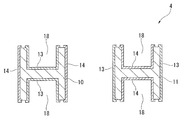
- FIG. 7 is a sectional view taken along line BB in FIG. FIG.
- FIG. 8 is a perspective view of a glass frit constituting a through electrode in the piezoelectric vibrator shown in FIG.
- FIG. 9 is a perspective view of a housing used for manufacturing the piezoelectric vibrator shown in FIG.
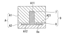
- FIG. 10 is a diagram illustrating one process in manufacturing the housing illustrated in FIG. 9, and is a diagram illustrating a state in which a base material is disposed between forging dies.
- FIG. 11 is a diagram illustrating a state in which the casing is forged with a forging die after the state illustrated in FIG. 10.
- FIG. 12 is a flowchart showing a flow when the piezoelectric vibrator shown in FIG. 1 is manufactured.
- FIG. 13 is a diagram showing a step in manufacturing the piezoelectric vibrator according to the flowchart shown in FIG. 12, and is a diagram showing a state in which a plurality of recesses are formed on the lid substrate wafer that is the base of the lid substrate.
- FIG. 14 is a diagram showing one process when the piezoelectric vibrator is manufactured according to the flowchart shown in FIG. 12, and shows a state in which a plurality of through holes are formed in the base substrate wafer which is the base substrate.
- FIG. FIG. 15 is a view of the state shown in FIG. 14 as seen from the cross section of the base substrate wafer.
- FIG. 16 is a diagram illustrating a process for manufacturing a piezoelectric vibrator according to the flowchart illustrated in FIG.
- FIG. 17 is a diagram showing one step in manufacturing the piezoelectric vibrator along the flowchart shown in FIG. 12, and is a diagram showing a state in which a laminate material is pasted after the state shown in FIG.
- FIG. 18 is a diagram showing a step in manufacturing the piezoelectric vibrator according to the flowchart shown in FIG. 12, and shows a state where glass frit is filled in the through hole after the state shown in FIG.
- FIG. 19 is a diagram illustrating a process of manufacturing the piezoelectric vibrator according to the flowchart illustrated in FIG.
- FIG. 20 is a diagram illustrating a process for manufacturing the piezoelectric vibrator according to the flowchart illustrated in FIG. 12, and illustrates a state in which the pasty glass frit is temporarily dried after the state illustrated in FIG. 19.
- FIG. 21 is a diagram illustrating a process for manufacturing the piezoelectric vibrator according to the flowchart illustrated in FIG. 12, and illustrates a process of peeling the laminate material after the state illustrated in FIG. 20.
- FIG. 22 is a diagram showing a step in manufacturing the piezoelectric vibrator according to the flowchart shown in FIG. 12, and after the state shown in FIG.
- FIG. 21 the head of the housing and the surface of the base substrate wafer are shown. It is a figure which shows the process of grind
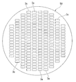
- FIG. 23 is a diagram showing a step in manufacturing the piezoelectric vibrator according to the flowchart shown in FIG. 12, and after the state shown in FIG. 22, the bonding film and the routing electrode are formed on the upper surface of the base substrate wafer. It is a figure which shows the state which patterned. 24 is an overall view of the base substrate wafer in the state shown in FIG.
- FIG. 25 is a diagram showing one process when the piezoelectric vibrator is manufactured according to the flowchart shown in FIG.
- FIG. 26 is a diagram showing one process when the piezoelectric vibrator is manufactured along the flowchart shown in FIG. 12, and is a diagram showing a state in which the gas generated inside the glass frit escapes to the outside in the firing process.
- FIG. 27 is a cross-sectional view of the piezoelectric vibrator of the second embodiment according to the invention.
- FIG. 28 is an enlarged view of a portion X shown in FIG.
- FIG. 29 is an exploded perspective view of the piezoelectric vibrator shown in FIG.
- FIG. 30 is a block diagram showing an embodiment of an oscillator according to the present invention.
- FIG. 31 is a configuration diagram showing an embodiment of an electronic apparatus according to the invention.
- FIG. 32 is a block diagram showing an embodiment of a radio timepiece according to the present invention.
- the piezoelectric vibrator 1 of the present embodiment is a surface mount type (two-layer structure type), in which a base substrate 2 and a lid substrate 3 (a pair of substrates) are stacked.
- the piezoelectric vibrating piece 4 is a tuning fork type vibrating piece formed of a piezoelectric material such as quartz crystal, lithium tantalate or lithium niobate, and when a predetermined voltage is applied. It vibrates.
- the piezoelectric vibrating reed 4 includes a pair of vibrating arm portions 10 and 11 arranged in parallel, a base portion 12 that integrally fixes the base end sides of the pair of vibrating arm portions 10 and 11, and a pair of vibrating arm portions 10.
- the piezoelectric vibrating reed 4 includes groove portions 18 formed along the longitudinal direction of the vibrating arm portions 10 and 11 on both main surfaces of the pair of vibrating arm portions 10 and 11.
- the groove portion 18 is formed from the proximal end side of the vibrating arm portions 10 and 11 to the vicinity of the middle.
- the excitation electrode 15 including the first excitation electrode 13 and the second excitation electrode 14 is an electrode that vibrates the pair of vibrating arm portions 10 and 11 at a predetermined resonance frequency in a direction approaching or separating from each other. Patterned on the outer surfaces of the vibrating arm portions 10 and 11 while being electrically separated from each other.
- the first excitation electrode 13 is mainly formed on the groove portion 18 of one vibration arm portion 10 and on both side surfaces of the other vibration arm portion 11, and the second excitation electrode 14 is formed on one side. Are formed mainly on both side surfaces of the vibrating arm portion 10 and on the groove portion 18 of the other vibrating arm portion 11.
- first excitation electrode 13 and the second excitation electrode 14 are electrically connected to the mount electrodes 16 and 17 via the extraction electrodes 19 and 20 on both main surfaces of the base portion 12, respectively.
- a voltage is applied to the piezoelectric vibrating reed 4 via the mount electrodes 16 and 17.
- the excitation electrode 15, the mount electrodes 16 and 17, and the extraction electrodes 19 and 20 described above are made of a conductive film such as chromium (Cr), nickel (Ni), aluminum (Al), or titanium (Ti). It is formed.
- a weight metal film 21 for adjusting (frequency adjustment) so as to vibrate its own vibration state within a predetermined frequency range is coated on the tips of the pair of vibrating arm portions 10 and 11.
- the weight metal film 21 is divided into a coarse adjustment film 21a used when the frequency is roughly adjusted and a fine adjustment film 21b used when the frequency is finely adjusted.
- the piezoelectric vibrating reed 4 configured in this manner is bump-bonded to the upper surface (first surface) 2a of the base substrate 2 using bumps B such as gold as shown in FIGS. More specifically, bump bonding is performed in a state where a pair of mount electrodes 16 and 17 are in contact with two bumps B formed on lead electrodes 36 and 37, which will be described later, patterned on the upper surface 2a of the base substrate 2. Has been. As a result, the piezoelectric vibrating reed 4 is supported in a state of floating from the upper surface 2a of the base substrate 2, and the mount electrodes 16 and 17 and the routing electrodes 36 and 37 are electrically connected to each other. .
- the lid substrate 3 is a transparent insulating substrate made of a glass material, for example, soda-lime glass, and is formed in a substantially plate shape as shown in FIGS.
- a rectangular recess 3 a in which the piezoelectric vibrating reed 4 is accommodated is formed on the bonding surface side to which the base substrate 2 is bonded.
- the recess 3 a is a cavity recess that is formed between the substrates 2 and 3 and serves as a cavity C that accommodates the piezoelectric vibrating reed 4 when the substrates 2 and 3 are overlapped.
- the lid substrate 3 is anodically bonded to the base substrate 2 with the recess 3a facing the base substrate 2 side.
- the base substrate 2 is a transparent insulating substrate made of a glass material, for example, soda lime glass, like the lid substrate 3, and has a size that can be superimposed on the lid substrate 3 as shown in FIGS. It is formed in a substantially plate shape.
- the base substrate 2 is formed with a pair of through holes (through holes) 30 and 31 that penetrate the base substrate 2. At this time, the pair of through holes 30 and 31 are formed so as to be accommodated in the cavity C. More specifically, in the through holes 30 and 31 of the present embodiment, one through hole 30 is formed at a position corresponding to the base 12 side of the mounted piezoelectric vibrating reed 4, and the distal ends of the vibrating arm portions 10 and 11 are formed.
- the other through hole 31 is formed at a position corresponding to.
- a through hole having a tapered cross section whose diameter gradually decreases from the lower surface 2b of the base substrate 2 toward the upper surface 2a will be described as an example.
- a through hole that penetrates straight may be used. In any case, it only needs to penetrate the base substrate 2.
- a pair of through electrodes 32 and 33 formed so as to fill the through holes 30 and 31 are formed.
- the through electrodes 32 and 33 are formed by the glass frit 6 and the core member 7 that are integrally fixed to the through holes 30 and 31 by firing. 31 are completely closed to maintain the airtightness in the cavity C, and the external electrodes 38 and 39 to be described later and the routing electrodes 36 and 37 are electrically connected.
- the glass frit 6 is obtained by baking paste-like glass frit 6a (see FIG. 18).
- the glass frit 6 is formed in a cylindrical shape having flat ends and substantially the same thickness as the base substrate 2.
- a core material portion 7 is disposed so as to penetrate the glass frit 6.
- the outer shape of the glass frit 6 is formed in a conical shape (tapered cross section) according to the shape of the through holes 30 and 31.
- the glass frit 6 is fired while being embedded in the through holes 30 and 31, and is firmly fixed to the through holes 30 and 31.
- the core material portion 7 is a conductive core material formed in a cylindrical shape from a metal material, and is formed so that both ends are flat and have the same thickness as the thickness of the base substrate 2, similar to the glass frit 6. ing.
- the core portion 7 is located in the center hole 6 c of the glass frit 6 and is firmly fixed to the glass frit 6 by firing the glass frit 6. That is, the core member 7 is disposed in the through holes 30 and 31 and electrically connects the piezoelectric vibrating reed 4 and the outside.
- the through holes 30 and 31 and the core are formed by the glass frit 6 filled and fired between the through holes 30 and 31 and the core member 7. The space between the material portions 7 is sealed to maintain the airtightness in the cavity C.
- the bonding film 35 is formed along the periphery of the base substrate 2 so as to surround the periphery of the recess 3 a formed in the lid substrate 3.
- the pair of lead-out electrodes 36 and 37 electrically connect one of the through electrodes 32 and 33 of the pair of through electrodes 32 and 33 to one of the mount electrodes 16 of the piezoelectric vibrating reed 4 and the other through electrode. 33 and the other mount electrode 17 of the piezoelectric vibrating reed 4 are patterned so as to be electrically connected. More specifically, the one lead-out electrode 36 is formed directly above the one through electrode 32 so as to be positioned directly below the base 12 of the piezoelectric vibrating piece 4. The other routing electrode 37 is routed from the position adjacent to the one routing electrode 36 to the distal end side of the vibrating arm portions 10 and 11 along the vibrating arm portions 10 and 11, and then the other through electrode 33. It is formed to be located directly above.
- Bumps B are formed on the pair of lead-out electrodes 36 and 37, and the piezoelectric vibrating reed 4 is mounted using the bumps B.
- one mount electrode 16 of the piezoelectric vibrating reed 4 is electrically connected to one through electrode 32 through one routing electrode 36, and the other mount electrode 17 is passed through the other routing electrode 37 to the other penetration electrode.
- the electrode 33 is electrically connected.
- external electrodes 38 and 39 are formed on the lower surface 2b of the base substrate 2 so as to be electrically connected to the pair of through electrodes 32 and 33, respectively. Yes. That is, one external electrode 38 is electrically connected to the first excitation electrode 13 of the piezoelectric vibrating reed 4 via one through electrode 32 and one routing electrode 36. The other external electrode 39 is electrically connected to the second excitation electrode 14 of the piezoelectric vibrating reed 4 via the other through electrode 33 and the other routing electrode 37.
- a predetermined drive voltage is applied to the external electrodes 38 and 39 formed on the base substrate 2.
- a current can flow through the excitation electrode 15 including the first excitation electrode 13 and the second excitation electrode 14 of the piezoelectric vibrating reed 4, and is predetermined in a direction in which the pair of vibrating arm portions 10 and 11 are approached and separated.
- Can be vibrated at a frequency of The vibration of the pair of vibrating arm portions 10 and 11 can be used as a time source, a control signal timing source, a reference signal source, and the like.
- the housing 9 includes a flat head portion 8 and a core portion 7 that protrudes from the back surface of the head portion 8.
- the core member 7 protrudes in a cylindrical shape along a direction substantially perpendicular to the back surface of the head 8 from above the head 8 and has a flat tip.
- the head 8 is formed in a circular shape in plan view, and the core member 7 protrudes from the central portion of the head 8 in plan view.
- the length (projection amount) of the core member 7 is, for example, a length shorter by 0.02 mm than the thickness of the base substrate wafer 40 before the polishing step described later.
- a gas escape passage 8 a that communicates from the base end of the core member 7 to the side surface of the head 8 is formed on the back surface of the head 8 of the housing 9.
- the gas escape passage 8 a has a linear shape in the plan view so as to be radial in the plan view on the back surface of the head 8 around the base end of the core member 7. It is constituted by a plurality of concave grooves.
- four gas escape passages 8 a are formed around the central axis of the housing 9 at equal intervals. Note that the depth of the gas escape passage 8a is, for example, about half the thickness of the head 8.
- the housing 9 shown above is manufactured by die forging the base material D of the housing 9 as shown in FIGS.
- a forging die A including an upper die A1 formed with a recess A11 that forms the outer shape of the core portion 7 and a lower die A2 formed with a recess A21 that forms the outer shape of the head 8 is used.
- the base material D of the casing 9 is forged.
- the base material D is made of, for example, an Fe—Ni alloy, Kovar or the like.
- the gas escape passage 8a is formed at the same time when the casing 9 is forged.
- a flow path convex portion A12 corresponding to the gas escape flow path 8a is formed in a portion adjacent to the edge of the concave portion A11 of the upper mold A1, and at the time of the die forging, the flow path convex portion A12 A gas escape passage 8a is formed.
- the housing 9 can be manufactured more efficiently than when the gas escape passage 8a is processed after the outer shape of the housing 9 is die-forged.
- piezoelectric vibrator manufacturing method Next, a manufacturing method for manufacturing a plurality of the piezoelectric vibrators 1 described above at once using the casing 9, the base substrate wafer 40, and the lid substrate wafer 50 will be described with reference to the flowchart shown in FIG. explain.
- the piezoelectric vibrating reed manufacturing step is performed to manufacture the piezoelectric vibrating reed 4 shown in FIGS. 5 to 7 (S10).
- a quartz Lambert rough is first sliced at a predetermined angle to obtain a wafer having a constant thickness.
- the wafer is lapped and roughly processed, and then the work-affected layer is removed by etching, and then mirror polishing such as polishing is performed to obtain a wafer having a predetermined thickness.
- the wafer is patterned with the outer shape of the piezoelectric vibrating piece 4 by a photolithography technique, and a metal film is formed and patterned.
- Lead electrodes 19 and 20, mount electrodes 16 and 17, and weight metal film 21 are formed. Thereby, the some piezoelectric vibrating piece 4 is producible.
- the resonance frequency is coarsely adjusted. This is done by irradiating the coarse adjustment film 21a of the weight metal film 21 with laser light to evaporate a part thereof and changing the weight. Note that fine adjustment for adjusting the resonance frequency with higher accuracy is performed after mounting. This will be described later.
- a first wafer manufacturing process is performed in which a lid substrate wafer 50 to be the lid substrate 3 later is manufactured up to a state immediately before anodic bonding (S20).
- a disk-shaped lid substrate wafer 50 is formed by removing the outermost work-affected layer by etching or the like ( S21).
- a recess forming process is performed in which a plurality of cavity recesses 3a are formed in the matrix direction on the bonding surface of the lid substrate wafer 50 by a method such as pressing or etching (S22). At this point, the first wafer manufacturing process is completed.
- a second wafer manufacturing process is performed in which the base substrate wafer 40 to be the base substrate 2 is manufactured up to the state immediately before anodic bonding (S30).
- a disc-shaped base substrate wafer 40 is formed by removing the outermost work-affected layer by etching or the like (S31).
- the base substrate wafer 40 is formed, for example, to be thicker by 0.02 mm than the length of the core portion 7 of the housing 9.
- a through electrode forming step for forming a plurality of pairs of through electrodes 32 and 33 on the base substrate wafer 40 is performed (S30A).
- the through electrode forming step 30A will be described in detail.
- a through-hole forming step (S32) for forming a plurality of pairs of through-holes 30 and 31 penetrating the base substrate wafer 40 is performed.
- the dotted line M shown in FIG. 14 illustrates a cutting line that is cut in a cutting process to be performed later.
- sandblasting is performed from the lower surface 40 b side of the base substrate wafer 40.
- through holes 30 and 31 having a tapered cross section whose diameter gradually decreases from the lower surface 40b of the base substrate wafer 40 toward the upper surface (first surface) 40a can be formed. .
- a plurality of pairs of through-holes 30 and 31 are formed so as to be accommodated in the recess 3a formed in the lid substrate wafer 50.
- one through hole 30 is formed on the base 12 side of the piezoelectric vibrating reed 4 and the other through hole 31 is formed on the distal end side of the vibrating arm portions 10 and 11.
- a housing arrangement step (S33) is performed in which the core portion 7 of the housing 9 is inserted into the plurality of through holes 30 and 31, and the housing 9 is placed on the base substrate wafer 40.
- the core member 7 is inserted until the back surface of the head 8 of the housing 9 comes into contact with the upper surface 40 a of the base substrate wafer 40.
- the core member 7 protrudes from the back surface of the head 8 in a direction substantially perpendicular to it, it is a simple operation that only pushes the head 8 until it contacts the upper surface 40a of the base substrate wafer 40.
- the core part 7 can be disposed in the through holes 30 and 31 and the axial direction of the core part 7 and the axial direction of the through holes 30 and 31 can be substantially matched.
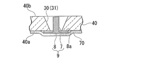
- a laminate material attaching step (S34) is performed in which a laminate material 70 is attached to the upper surface 40a of the base substrate wafer 40 so as to cover the head 8 of the housing 9.
- the laminate material 70 is pasted over substantially the entire upper surface 40 a of the base substrate wafer 40.
- the laminate material 70 is, for example, one obtained by applying a thermoplastic adhesive such as acrylic to a paper tape body, and preferably has a thickness of 50 ⁇ m or more and 200 ⁇ m or less.
- the laminate material 70 can hold the upper surface 40a of the base substrate wafer 40 and the back surface of the head 8 of the housing 9 without any gap.
- the paste-like glass frit 6a is reliably placed in the through holes 30 and 31 in the glass frit filling step (S35) described later. Can be filled.
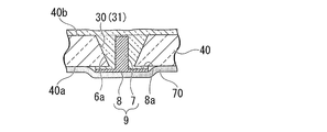
- a paste-like glass frit 6 a is placed between the through holes 30 and 31 and the core portion 7.
- a glass frit filling step of filling is performed (S35).
- filling is performed by applying paste-like glass frit 6 a from the lower surface 40 b side of the base substrate wafer 40 in the through holes 30 and 31.
- the gas escape passage 8a is formed on the back surface of the housing 9, a portion of the pasty glass frit 6a located around the base end of the core portion 7 passes through the gas escape passage 8a. It is exposed from the side surface of the portion 8 toward the outside.
- the laminate material 70 is affixed to the upper surface 40a of the base substrate wafer 40, it is possible to reliably prevent the paste-like glass frit 6a from leaking to the outside.
- the base substrate wafer 40 and the housing 9 can be held by the laminate material 70, and the housing 9 can be reliably prevented from falling off the base substrate wafer 40.
- the glass frit filling step a large amount of the glass frit 6a is applied so that the glass frit 6a is surely filled in the through holes 30 and 31. Accordingly, the glass frit 6 a is also applied to the lower surface 40 b of the base substrate wafer 40. If the glass frit 6a is baked in this state, the time required for the polishing step described later increases, so a glass frit removing step is performed to remove excess glass frit 6a before baking (S36).
- this glass frit removing step for example, a resin squeegee 45 is used, and the tip 45a of the squeegee 45 is brought into contact with the lower surface 40b of the base substrate wafer 40 and moved along the lower surface 40b.
- the glass frit 6a protruding from the through holes 30 and 31 is removed.
- the excess glass frit 6a can be reliably removed by a simple operation.
- the squeegee 45 passes through the upper portions of the through holes 30 and 31. It becomes possible to suppress that the front-end
- a temporary drying step of heating and temporarily drying the filled paste-like glass frit 6a is performed (S37).
- the glass frit 6a is heated at a temperature lower than that in the firing step described later.
- the glass frit 6a is temporarily dried by heating, for example, at 80 degrees for 30 minutes.
- the fluidity of the pasty glass frit 6 a is reduced, and the temporarily dried glass frit 6 is maintained in the shape held in the through holes 30 and 31.
- the adhesive force of the thermoplastic adhesive of the laminate material 70 falls.
- a laminate material peeling step (S38) for peeling the laminate material 70 from the upper surface 40a of the base substrate wafer 40 is performed.
- the adhesive strength of the thermoplastic adhesive of the laminate material 70 is reduced in the temporary drying step (S37), the laminate material 70 can be easily and reliably peeled off, and the production efficiency of the piezoelectric vibrator 1 is improved. Can be improved.
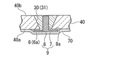
- a firing step (S39) is performed in which the glass frit 6 filled in the through holes 30 and 31 is fired at a predetermined temperature.
- the through holes 30 and 31, the glass frit 6 embedded in the through holes 30 and 31, and the housing 9 disposed in the glass frit 6 are fixed to each other and fixed integrally.
- the space between the holes 30 and 31 and the core member 7 is sealed.
- the entire head portion 8 is fired, the axial direction of the core portion 7 and the axial directions of the through holes 30 and 31 are substantially matched, so that both can be fixed integrally.
- the heating temperature and heating time will be described in detail.
- the glass frit 6 is heated at, for example, 350 ° C. for 30 to 60 minutes to burn the binder contained in the glass frit 6.
- Temporary firing binder removal
- the glass frit 6 is heated at, for example, 530 degrees for 10 minutes, and the glass frit 6 is finally fired. Thereby, the temporarily dried glass frit 6 is baked and solidified.
- a polishing process is performed to polish the upper surface 40a side of the base substrate wafer 40 and remove the head 8 of the housing 9 (S40).
- the head 8 that has played the role of positioning the glass frit 6 and the core member 7 is removed, leaving only the core member 7 inside the glass frit 6, and the core member 7 is removed from the base substrate wafer 40. It can be exposed to the upper surface 40a.
- the lower surface 40b side of the base substrate wafer 40 is polished to expose the tip of the core portion 7 and to flatten the lower surface 40b of the base substrate wafer 40.
- a plurality of pairs of through electrodes 32 and 33 in which the glass frit 6 and the core member 7 are integrally fixed can be obtained.
- the surface (upper surface 40a and lower surface 40b) of the base substrate wafer 40 and both ends of the glass frit 6 and the core member 7 are substantially flush with each other. That is, the surface of the base substrate wafer 40 and the surfaces of the through electrodes 32 and 33 can be substantially flush with each other. Note that when the polishing process is performed, the through electrode forming process (S30A) is completed.
- a conductive material is patterned on the upper surface 40a of the base substrate wafer 40, and as shown in FIGS. 23 and 24, a bonding film forming step for forming the bonding film 35 is performed (S41), and each pair of pairs is formed.
- a dotted line M shown in FIG. 23 and FIG. 24 illustrates a cutting line that is cut in a subsequent cutting step.
- the through electrodes 32 and 33 are substantially flush with the upper surface 40a of the base substrate wafer 40 as described above.
- the routing electrodes 36 and 37 patterned on the upper surface of the base substrate wafer 40 are in close contact with the through electrodes 32 and 33 without generating a gap therebetween. As a result, it is possible to ensure the electrical conductivity between the one routing electrode 36 and the one through electrode 32 and the electrical conductivity between the other routing electrode 37 and the other through electrode 33. At this point, the second wafer manufacturing process is completed.
- FIG. 12 it is set as the process order which performs the routing electrode formation process (S42) after the bonding film formation process (S41), but on the contrary, after the routing electrode formation process (S42), the bonding film formation is performed.
- the step (S41) may be performed, or both steps may be performed simultaneously. Regardless of the order of steps, the same effects can be obtained. Therefore, the process order may be changed as necessary.
- a mounting process is performed in which the produced plurality of piezoelectric vibrating reeds 4 are joined to the upper surface 40a of the base substrate wafer 40 via the routing electrodes 36 and 37, respectively (S50).
- bumps B such as gold are formed on the pair of lead-out electrodes 36 and 37, respectively.
- the piezoelectric vibrating piece 4 is pressed against the bump B while heating the bump B to a predetermined temperature.
- the piezoelectric vibrating reed 4 is mechanically supported by the bumps B, and the mount electrodes 16 and 17 and the routing electrodes 36 and 37 are electrically connected.
- the pair of excitation electrodes 15 of the piezoelectric vibrating reed 4 are in a conductive state with respect to the pair of through electrodes 32 and 33, respectively.
- the piezoelectric vibrating reed 4 is bump-bonded, it is supported in a state where it floats from the upper surface 40 a of the base substrate wafer 40.
- an overlaying process for overlaying the lid substrate wafer 50 on the base substrate wafer 40 is performed (S60). Specifically, both wafers 40 and 50 are aligned at the correct position while using a reference mark (not shown) as an index. As a result, the mounted piezoelectric vibrating reed 4 is housed in a cavity C surrounded by the recess 3 a formed in the base substrate wafer 40 and the wafers 40 and 50.
- the superposed two wafers 40 and 50 are put in an anodic bonding apparatus (not shown), and a predetermined voltage is applied in a predetermined temperature atmosphere to perform anodic bonding (S70). Specifically, a predetermined voltage is applied between the bonding film 35 and the lid substrate wafer 50. As a result, an electrochemical reaction occurs at the interface between the bonding film 35 and the lid substrate wafer 50, and the two are firmly bonded and anodically bonded. Accordingly, the piezoelectric vibrating reed 4 can be sealed in the cavity C, and the wafer body 60 shown in FIG. 25 in which the base substrate wafer 40 and the lid substrate wafer 50 are bonded can be obtained. In FIG.
- the wafer body 60 is shown in an exploded state for easy viewing of the drawing, and the bonding film 35 is not shown from the base substrate wafer 40.
- the dotted line M shown in FIG. 25 has shown the cutting line cut
- the through holes 30 and 31 formed in the base substrate wafer 40 are completely closed by the through electrodes 32 and 33, so that the airtightness in the cavity C is reduced. Will not be damaged through.
- the glass frit 6 and the core member 7 are fixed to each other by firing and are firmly fixed to the through holes 30 and 31, so that the airtightness in the cavity C is reliably maintained. can do.
- a conductive material is patterned on the lower surface 40b of the base substrate wafer 40, and a pair of external electrodes 38 and 39 electrically connected to the pair of through electrodes 32 and 33, respectively.
- An external electrode forming step of forming a plurality of electrodes is performed (S80). Through this step, the piezoelectric vibrating reed 4 sealed in the cavity C can be operated using the external electrodes 38 and 39. In particular, even when this step is performed, the through electrodes 32 and 33 are substantially flush with the lower surface 40b of the base substrate wafer 40 as in the case of forming the lead-out electrodes 36 and 37.
- the external electrodes 38 and 39 are in close contact with the through electrodes 32 and 33 without generating a gap or the like therebetween. Thereby, the continuity between the external electrodes 38 and 39 and the through electrodes 32 and 33 can be ensured.
- a fine adjustment step of finely adjusting the frequency of each piezoelectric vibrator 1 sealed in the cavity C to be within a predetermined range is performed (S90). More specifically, a voltage is applied to the pair of external electrodes 38 and 39 formed on the lower surface 40 b of the base substrate wafer 40 to vibrate the piezoelectric vibrating reed 4. Then, laser light is irradiated from the outside through the lid substrate wafer 50 while measuring the frequency, and the fine adjustment film 21b of the weight metal film 21 is evaporated. Thereby, since the weight of the tip end side of the pair of vibrating arm portions 10 and 11 changes, the frequency of the piezoelectric vibrating piece 4 can be finely adjusted so as to be within a predetermined range of the nominal frequency.
- a cutting process is performed in which the bonded wafer body 60 is cut along the cutting line M shown in FIG. 25 into smaller pieces (S100).
- the piezoelectric vibration piece 4 is sealed in the cavity C formed between the base substrate 2 and the lid substrate 3 that are anodically bonded to each other, and the two-layer structure surface mount type piezoelectric vibration shown in FIG. A plurality of children 1 can be manufactured at a time.
- the order of processes in which the fine adjustment process (S90) is performed may be used.
- fine adjustment step (S90) fine adjustment can be performed in the state of the wafer body 60, so that the plurality of piezoelectric vibrators 1 can be finely adjusted more efficiently. Therefore, it is preferable because throughput can be improved.
- the core material portion 7 of the paste-like glass frit 6a filled in the glass frit filling process is formed.
- a portion located around the base end is exposed to the outside from the side surface of the head 8 through the gas escape passage 8a. Therefore, in the firing step, the gas generated inside the glass frit due to the burning of the binder contained in the glass frit 6 can be discharged outside through the gas escape passage 8a.
- the gas generated inside the glass frit due to the burning of the binder contained in the glass frit 6 can be discharged outside through the gas escape passage 8a.
- the laminate material 70 has elasticity, it is possible to reduce a load applied to a portion where the base substrate wafer 40 and the casing 9 are in contact with each other in the glass frit filling process, and the base substrate wafer.
- the generation of cracks in 40 can be suppressed.
- the package 5 when the package 5 is manufactured, it is possible to suppress leakage of the glass frit 6 to the outside and generation of cracks in the base substrate wafer 40 while suppressing formation of bubbles inside the glass frit 6. 5 The production yield can be improved.
- the firing step is performed in a state where the laminate material 70 is peeled off. Therefore, when the glass frit 6 is heated to a temperature high enough to be baked in the baking process, the heating does not affect the quality of the package 5 due to, for example, burning of the tape body. Can be reliably manufactured.
- the thickness of the laminate material 50 by setting the thickness of the laminate material 50 to 50 ⁇ m or more and 200 ⁇ m or less, an appropriate cushioning property can be obtained for the laminate material 70, and the base substrate wafer 40 is filled when the glass frit 6 a is filled in the through holes 30 and 31. It is possible to prevent cracks from occurring. If the laminate material 70 is too thin, an appropriate cushioning property cannot be obtained, so that there is a possibility that the base substrate wafer 40 may crack. On the other hand, if the laminate material 70 is too thick, the cushioning property becomes too large, so that a load is applied to the contact portion between the base substrate wafer 40 and the housing 9, and the base substrate wafer 40 may be cracked.
- the package 5 according to the present embodiment since the package 5 according to the present embodiment is manufactured by the manufacturing method described above, it has excellent airtightness and high quality.
- the piezoelectric vibrator 1 according to the present embodiment since the piezoelectric vibrating piece 4 is housed in a cavity having excellent airtightness, the piezoelectric vibrating piece 4 is hardly affected by dust or the like and operates with high accuracy. . Further, the use of the package 5 in which the formation of bubbles in the glass frit 6 is suppressed and the quality is improved is used. As described above, the piezoelectric vibrator 1 with high quality can be obtained.
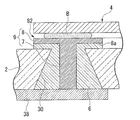
- the package 81 includes a head (a flat plate portion) 8 that is connected to the core member 7 and disposed in the cavity C. It has been. As shown in FIG. 28, the head 8 is disposed in the cavity C so as to cover the through holes 30 and 31, respectively. That is, in the present embodiment, the head portion 8 of the housing 9 is left in the cavity C without being polished.
- the head 8 is disposed so as to cover the through holes 30 and 31, while the glass frit 6 is exposed in the cavity C.
- the glass frit 6 is filled in the gas escape passage 8 a of the head 8, and a portion of the glass frit 6 filled at the edge of the gas escape passage 8 a is exposed in the cavity C. is doing.
- the pair of through electrodes 82 and 83 includes a glass frit 6, a core member 7, and a head 8. Further, only one lead electrode 84 is formed, and it is not formed on the side of one through electrode 82 located directly below the base 12 of the piezoelectric vibrating piece 4. That is, the routing electrode 84 is routed from the position adjacent to the one through electrode 82 to the distal end side of the vibrating arm portions 10, 11 along the vibrating arm portions 10, 11, and then the head of the other through electrode 83. 8 to be electrically connected. Further, bumps B are respectively formed on a portion of the routing electrode 84 adjacent to the one through electrode 82 and on each head 8 of the one through electrode 82.
- the process up to the firing step (S39) is performed in the same manner as the piezoelectric vibrator manufacturing method in the first embodiment.
- a polishing step is performed in which polishing is performed until the tip of the core member 7 is exposed on the lower surface 40b of the base substrate wafer 40 (S40).
- the head 8 of the housing 9 is left without being polished.
- the bonding film forming step (S41) and the lead-out electrode forming step (S42) and subsequent steps are performed in the same manner as in the piezoelectric vibrator manufacturing method according to the first embodiment.
- the same operational effects as those of the first embodiment can be obtained.
- the head 8 of the housing 9 is not polished in the polishing process, the production efficiency of the package 81 can be further improved.
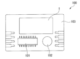
- the oscillator 100 according to the present embodiment is configured such that the piezoelectric vibrator 1 is an oscillator electrically connected to the integrated circuit 101.
- the piezoelectric vibrator 1 shown in the first embodiment is used as the piezoelectric vibrator, but the same applies to the piezoelectric vibrator 80 shown in the second embodiment. The effect of this can be achieved.
- the oscillator 100 includes a substrate 103 on which an electronic component 102 such as a capacitor is mounted. On the substrate 103, the integrated circuit 101 for the oscillator is mounted, and the piezoelectric vibrator 1 is mounted in the vicinity of the integrated circuit 101.
- the electronic component 102, the integrated circuit 101, and the piezoelectric vibrator 1 are electrically connected by a wiring pattern (not shown).
- Each component is molded with a resin (not shown).
- the piezoelectric vibrating reed 4 in the piezoelectric vibrator 1 vibrates. This vibration is converted into an electric signal by the piezoelectric characteristics of the piezoelectric vibrating piece 4 and input to the integrated circuit 101 as an electric signal.
- the input electrical signal is subjected to various processes by the integrated circuit 101 and is output as a frequency signal.
- the piezoelectric vibrator 1 functions as an oscillator.
- an RTC real-time clock
- a function for controlling the time, providing a time, a calendar, and the like can be added.
- the oscillator 100 of the present embodiment since the airtightness in the cavity C is reliably ensured and the high-quality piezoelectric vibrator 1 is provided, the oscillator 100 itself is similarly improved in quality. be able to. In addition to this, it is possible to obtain a highly accurate frequency signal that is stable over a long period of time.
- the portable information device 110 having the above-described piezoelectric vibrator 1 will be described as an example of the electronic device.
- the portable information device 110 according to the present embodiment is represented by, for example, a mobile phone, and is a development and improvement of a wrist watch in the related art. The appearance is similar to that of a wristwatch, and a liquid crystal display is arranged in a portion corresponding to a dial so that the current time and the like can be displayed on this screen.
- the portable information device 110 includes the piezoelectric vibrator 1 and a power supply unit 111 for supplying power.
- the power supply unit 111 is made of, for example, a lithium secondary battery.
- the power supply unit 111 includes a control unit 112 that performs various controls, a clock unit 113 that counts time, a communication unit 114 that communicates with the outside, a display unit 115 that displays various types of information, A voltage detection unit 116 that detects the voltage of the functional unit is connected in parallel.
- the power unit 111 supplies power to each functional unit.
- the control unit 112 controls each function unit to control the operation of the entire system such as transmission and reception of voice data, measurement and display of the current time, and the like.
- the control unit 112 includes a ROM in which a program is written in advance, a CPU that reads and executes the program written in the ROM, and a RAM that is used as a work area of the CPU.
- the clock unit 113 includes an integrated circuit including an oscillation circuit, a register circuit, a counter circuit, an interface circuit, and the like, and the piezoelectric vibrator 1.
- the piezoelectric vibrating piece 4 vibrates, and this vibration is converted into an electric signal by the piezoelectric characteristics of the crystal and is input to the oscillation circuit as an electric signal.
- the output of the oscillation circuit is binarized and counted by a register circuit and a counter circuit. Then, signals are transmitted to and received from the control unit 112 via the interface circuit, and the current time, current date, calendar information, and the like are displayed on the display unit 115.
- the communication unit 114 has functions similar to those of a conventional mobile phone, and includes a radio unit 117, a voice processing unit 118, a switching unit 119, an amplification unit 120, a voice input / output unit 121, a telephone number input unit 122, and a ring tone generation unit. 123 and a call control memory unit 124.
- the wireless unit 117 exchanges various data such as voice data with the base station via the antenna 125.
- the audio processing unit 118 encodes and decodes the audio signal input from the radio unit 117 or the amplification unit 120.
- the amplifying unit 120 amplifies the signal input from the audio processing unit 118 or the audio input / output unit 121 to a predetermined level.
- the voice input / output unit 121 includes a speaker, a microphone, and the like, and amplifies a ringtone and a received voice or collects a voice.
- the ring tone generator 123 generates a ring tone in response to a call from the base station.
- the switching unit 119 switches the amplifying unit 120 connected to the voice processing unit 118 to the ringing tone generating unit 123 only when an incoming call is received, so that the ringing tone generated in the ringing tone generating unit 123 is transmitted via the amplifying unit 120.
- the call control memory unit 124 stores a program related to incoming / outgoing call control of communication.
- the telephone number input unit 122 includes, for example, number keys from 0 to 9 and other keys. By pressing these number keys, a telephone number of a call destination is input.
- the voltage detection unit 116 detects the voltage drop and notifies the control unit 112 of the voltage drop.
- the predetermined voltage value at this time is a value set in advance as a minimum voltage necessary for stably operating the communication unit 114, and is, for example, about 3V.
- the control unit 112 prohibits the operations of the radio unit 117, the voice processing unit 118, the switching unit 119, and the ring tone generation unit 123. In particular, it is essential to stop the operation of the wireless unit 117 with high power consumption. Further, the display unit 115 displays that the communication unit 114 has become unusable due to insufficient battery power.
- the operation of the communication unit 114 can be prohibited by the voltage detection unit 116 and the control unit 112, and that effect can be displayed on the display unit 115.
- This display may be a text message, but as a more intuitive display, a x (X) mark may be attached to the telephone icon displayed at the top of the display surface of the display unit 115.
- the function of the communication part 114 can be stopped more reliably by providing the power supply cutoff part 126 that can selectively cut off the power of the part related to the function of the communication part 114.
- the portable information device 110 of the present embodiment since the airtightness in the cavity C is reliably ensured and the high-quality piezoelectric vibrator 1 is provided, the portable information device itself has the same high quality. Can be achieved. In addition to this, it is possible to display highly accurate clock information that is stable over a long period of time.
- the radio timepiece 130 of the present embodiment includes the piezoelectric vibrator 1 that is electrically connected to the filter unit 131.
- the radio timepiece 130 receives a standard radio wave including timepiece information and is accurate. It is a clock with a function of automatically correcting and displaying the correct time.
- transmitting stations transmitting stations that transmit standard radio waves in Fukushima Prefecture (40 kHz) and Saga Prefecture (60 kHz), each transmitting standard radio waves.
- Long waves such as 40 kHz or 60 kHz have the property of propagating the surface of the earth and the property of propagating while reflecting the ionosphere and the surface of the earth, so the propagation range is wide, and the above two transmitting stations cover all of Japan. is doing.
- the antenna 132 receives a long standard wave of 40 kHz or 60 kHz.
- the long-wave standard radio wave is obtained by subjecting time information called a time code to AM modulation on a 40 kHz or 60 kHz carrier wave.
- the received long standard wave is amplified by the amplifier 133 and filtered and tuned by the filter unit 131 having the plurality of piezoelectric vibrators 1.
- the piezoelectric vibrator 1 according to this embodiment includes crystal vibrator portions 138 and 139 having resonance frequencies of 40 kHz and 60 kHz that are the same as the carrier frequency.
- the filtered signal having a predetermined frequency is detected and demodulated by the detection and rectification circuit 134. Subsequently, the time code is taken out via the waveform shaping circuit 135 and counted by the CPU 136.
- the CPU 136 reads information such as the current year, accumulated date, day of the week, and time. The read information is reflected in the RTC 137, and accurate time information is displayed. Since the carrier wave is 40 kHz or 60 kHz, the crystal vibrator units 138 and 139 are preferably vibrators having the tuning fork type structure described above.
- the frequency of the long standard radio wave is different overseas.
- a standard radio wave of 77.5 KHz is used. Accordingly, when the radio timepiece 130 that can be used overseas is incorporated in a portable device, the piezoelectric vibrator 1 having a frequency different from that in Japan is required.
- the radio timepiece 130 of the present embodiment the airtightness in the cavity C is reliably ensured, and the high quality piezoelectric vibrator 1 is provided. Can be achieved. In addition to this, it is possible to count time stably and with high accuracy over a long period of time.
- the gas escape passage 8 a communicates with the side surface of the head portion 8 from the base end of the core portion 7, but is not limited to this, and communicates with the surface of the head portion 8 from the base end of the core portion 7. It may be a thing.
- the gas escape passage for example, a through hole may be formed by penetrating from the back surface of the head 8 to the surface.
- the gas escape passage is not limited to those shown in the above embodiments.
- the shape of the core part 7 was formed in the column shape was demonstrated, you may make it a prism. Even in this case, the same effects can be obtained.
- the core member 7 it is preferable to use a material having a thermal expansion coefficient substantially equal to that of the base substrate 2 (base substrate wafer 40) and the glass frit 6 as the core member 7.
- the base substrate wafer 40, the glass frit 6, and the core member 7 are thermally expanded in the same manner. Therefore, depending on the difference in thermal expansion coefficient, excessive pressure is applied to the base substrate wafer 40 and the glass frit 6 to generate cracks, etc., or between the glass frit 6 and the through holes 30 and 31, or the glass frit.
- the grooved piezoelectric vibrating piece 4 in which the groove portions 18 are formed on both surfaces of the vibrating arm portions 10 and 11 has been described as an example, but there is no groove portion 18.
- a type of piezoelectric vibrating piece may be used.
- the tuning fork type piezoelectric vibrating piece 4 has been described as an example.
- the tuning fork type is not limited to the tuning fork type.
- it may be a thickness sliding vibration piece.
- the base substrate 2 and the lid substrate 3 are anodically bonded via the bonding film 35.
- the present invention is not limited to anodic bonding.
- anodic bonding is preferable because both substrates 2 and 3 can be firmly bonded.
- the piezoelectric vibrating reed 4 is bump-bonded.
- the present invention is not limited to bump bonding.
- the piezoelectric vibrating reed 4 may be joined with a conductive adhesive.
- the piezoelectric vibrating reed 4 can be lifted from the upper surface of the base substrate 2, and a minimum vibration gap necessary for vibration can be secured naturally. Therefore, it is preferable to perform bump bonding.
- the length of the core member 7 is set to be 0.02 mm shorter than the thickness of the base substrate wafer 40 before the polishing process has been described.
- the length can be freely set. Any configuration can be used as long as the squeegee 45 and the core member 7 do not come into contact with each other when the excess glass frit 6a is removed by the squeegee 45.
- the housing 9 shall have the front-end
- the glass frit removing step is performed.
- the present invention is not limited to this.
- the glass frit filling step instead of filling the upper surface 40a of the base substrate wafer 40 with the pasty glass frit 6a, the through holes 30, 31 are filled with the pasty glass frit 6a separately, It is good also as what does not perform a glass frit removal process.
- the laminate material 70 has a size that covers the entire upper surface 40a of the base substrate wafer.
- the laminate material 70 is pasted so as to cover the head 8 of the housing 9. If possible, the size of the laminate 70 is not limited to that shown in each of the embodiments.
- the laminate material 70 was used and each provided with the laminate material sticking process and the laminate material peeling process, it is not restricted to this, The laminate material 70 does not need to be used. Further, even when the laminate material 70 is used, the laminate material 70 is not limited to the one shown in each of the embodiments as long as the laminate material 70 has elasticity and adhesiveness. Furthermore, in each said embodiment, although the laminate material peeling process was performed after the temporary drying process, it is not restricted to this, For example, a temporary drying process does not need to be performed, and it laminates after a baking process. You may perform a material peeling process.
- each of the above embodiments the two substrates of the base substrate 2 and the lid substrate 3 are stacked to form the packages 5 and 81.
- the present invention is not limited to this.
- Three or more substrates may be laminated.
- each includes a flat base substrate and a lid substrate in which the concave portion is not formed, and a frame substrate having a through-opening that forms an outline of the concave portion in plan view, between the base substrate and the lid substrate.
- the frame substrates may be stacked so as to sandwich each other, and adjacent members may be joined to each other.
- the packages 5 and 81 are formed by being sandwiched between a plurality of substrates bonded together in a stacked state and a pair of substrates among the plurality of substrates, and the objects to be stored are hermetically sealed. If it is provided with the cavity accommodated in, it will not be restricted to what is shown by the said each embodiment.
- the packages 5 and 81 are provided with a pair of through electrodes 32, 33, 82, and 83.
- the present invention is not limited to this.
- the number of may be one, or three or more.
- the case where the piezoelectric vibrators 1 and 80 in which the piezoelectric vibrating reed 4 is housed in the cavity C of the packages 5 and 81 is described as an example.
- the stored items are not limited to this, and may be changed as appropriate.
- a plurality of piezoelectric vibrators 1 and 80 are manufactured at a time using a wafer-like substrate (base substrate wafer 40 and lid substrate wafer 50).
- the piezoelectric substrate 1 or 80 may be manufactured at a time by processing the base substrate 2 and the lid substrate 3 having dimensions adjusted to the dimensions of the base substrate 2 and the lid substrate 3 in advance.
Landscapes
- Physics & Mathematics (AREA)
- Acoustics & Sound (AREA)
- Chemical & Material Sciences (AREA)
- Crystallography & Structural Chemistry (AREA)
- Engineering & Computer Science (AREA)
- Manufacturing & Machinery (AREA)
- Piezo-Electric Or Mechanical Vibrators, Or Delay Or Filter Circuits (AREA)
- Oscillators With Electromechanical Resonators (AREA)
Abstract
Description
そこで、芯材部の形成に際し、ベース基板に形成された貫通孔内に金属部材を配置すると共に金属部材と貫通孔との間にペースト状のガラスフリットを充填し、充填されたガラスフリットを焼成して貫通孔と金属部材とガラスフリットとを一体的に固定させる方法が考えられる。この方法によれば、キャビティ内の気密性を確保することができる。
なお、このように鋲体及びガラスフリットを用いて芯材部を形成する場合には、一般的にガラスフリットの焼成後、鋲体の頭部を研磨(研削)して除去する。これにより、ベース基板、ガラスフリット及び芯材部を互いに面一にすることが可能となり、ベース基板上での各電極(引き回し電極や外部電極)の形成を確実に行うことができる。
この場合、ガラスフリット焼成後、鋲体の頭部を除去したときに、ガラスフリットの表面に凹部が残ってしまう。そして、ガラスフリットに凹部が残った状態でベース基板に引き回し電極や外部電極などを形成した場合、各電極を均一な厚みに形成することが難しく、一部分の厚みが極めて薄い電極が形成されてしまうことがある。この場合、経時劣化等により各電極において薄く形成された部分が局所的に断線してしまう恐れがあり、圧電振動片と外部電極との導通性が損なわれる可能性があった。
また、ガラスフリット焼成後、鋲体の頭部を除去しない場合であっても、ガラスフリット内部に形成された気泡を起点として、クラックや割れなどが発生する恐れがあった。
(1)本発明に係るパッケージの製造方法は、積層状態で隣接するもの同士が互いに接合された複数の基板と;前記複数の基板のうちの一対の基板に挟まれて形成され、被収納物を気密封止した状態で収納するキャビティと;前記一対の基板のうちの一方の基板であるベース基板を貫通する貫通孔内に配置され、前記被収納物と外部とを電気的に接続する芯材部と;前記貫通孔と前記芯材部との間に充填されると共に焼成され、両者間を封止するガラスフリットと;を備えるパッケージを、平板状の頭部と、前記頭部の裏面から突出する芯材部と、を有する鋲体を用いて製造するパッケージの製造方法であって、前記頭部の裏面が前記ベース基板の第1面に接触するまで前記貫通孔内に前記芯材部を挿入し、前記ベース基板に前記鋲体を配置する鋲体配置工程と;前記鋲体が配置された前記ベース基板において、前記貫通孔と前記芯材部との間にペースト状のガラスフリットを充填するガラスフリット充填工程と;充填された前記ガラスフリットを焼成して前記貫通孔と前記鋲体と前記ガラスフリットとを一体的に固定させ、前記貫通孔と前記芯材部との間を封止する焼成工程と;を備え、前記鋲体の頭部の裏面には、前記芯材部の基端から前記頭部の側面または表面に連通するガス逃げ流路が形成されている。
また、ラミネート材が弾性を具備しているので、ガラスフリット充填工程において、ベース基板と鋲体とが互いに接触する部分にかかる負荷を軽減させることが可能となり、ベース基板に亀裂が生じるのを抑制することができる。
以上より、パッケージの製造に際し、ガラスフリット内部での気泡の形成を抑制しつつ、ガラスフリットの外部への漏洩およびベース基板の亀裂の発生を抑制することが可能となり、パッケージ製造の歩留まりを向上することができる。
また、ラミネート材剥離工程を焼成工程前に行っていることから、焼成工程はラミネート材が剥離された状態で行われる。従って、焼成工程においてガラスフリットを焼成させる程度高温に加熱するときに、この加熱により例えばテープ本体が燃焼してパッケージの品質に影響を与えてしまうようなことがなく、高品質なパッケージを確実に製造することができる。
2 ベース基板
2a 上面(第1面)
3 リッド基板(基板)
4 圧電振動片(被収納体)
5、81 パッケージ
6 ガラスフリット
6a ペースト状のガラスフリット
7 芯材部
8 頭部(平板部)
9 鋲体
30、31 スルーホール(貫通孔)
40 ベース基板用ウエハ(ベース基板)
40a 上面(第1面)
50 リッド基板用ウエハ(基板)
70 ラミネート材
100 発振器
101 発振器の集積回路
110 携帯情報機器(電子機器)
113 電子機器の計時部
130 電波時計
131 電波時計のフィルタ部
C キャビティ
次に、本発明に係る第1実施形態を、図1~図26を参照して説明する。なお、本実施形態では、パッケージを圧電振動子に採用した場合を例に挙げて説明する。
図1~図4に示すように、本実施形態の圧電振動子1は、表面実装型(2層構造式)であって、ベース基板2及びリッド基板3(一対の基板)が積層されると共に互いに接合されて形成されたパッケージ5と、ベース基板2及びリッド基板3に挟まれてパッケージ5の内部に形成されたキャビティC内に気密封止された状態で収納される圧電振動片(被収納物)4と、を備えている。
図5~図7に示すように、圧電振動片4は、水晶、タンタル酸リチウムやニオブ酸リチウムなどの圧電材料から形成された音叉型の振動片であり、所定の電圧が印加されたときに振動するものである。
この圧電振動片4は、平行に配置された一対の振動腕部10、11と、一対の振動腕部10、11の基端側を一体的に固定する基部12と、一対の振動腕部10、11の外表面上に形成されて一対の振動腕部10、11を振動させる第1の励振電極13と第2の励振電極14とからなる励振電極15と、第1の励振電極13及び第2の励振電極14に電気的に接続されたマウント電極16、17とを有している。
また、本実施形態の圧電振動片4は、一対の振動腕部10、11の両主面上に、振動腕部10、11の長手方向に沿ってそれぞれ形成された溝部18を備えている。この溝部18は、振動腕部10、11の基端側から略中間付近まで形成されている。
なお、上述した励振電極15、マウント電極16、17及び引き出し電極19、20は、例えば、クロム(Cr)、ニッケル(Ni)、アルミニウム(Al)やチタン(Ti)などの導電性膜の被膜により形成されたものである。
次に、パッケージ5の構成について説明する。
上記リッド基板3は、ガラス材料、例えばソーダ石灰ガラスからなる透明の絶縁基板であり、図1、図3及び図4に示すように、略板状に形成されている。そして、ベース基板2が接合される接合面側には、圧電振動片4が収まる矩形状の凹部3aが形成されている。
この凹部3aは、両基板2、3が重ね合わされたときに、両基板2、3の間に形成され圧電振動片4を収容するキャビティCとなるキャビティ用の凹部である。そして、リッド基板3は、この凹部3aをベース基板2側に対向させた状態でベース基板2に対して陽極接合されている。
このベース基板2には、ベース基板2を貫通する一対のスルーホール(貫通孔)30、31が形成されている。この際、一対のスルーホール30、31は、キャビティC内に収まるように形成されている。より詳しく説明すると、本実施形態のスルーホール30、31は、マウントされた圧電振動片4の基部12側に対応した位置に一方のスルーホール30が形成され、振動腕部10、11の先端側に対応した位置に他方のスルーホール31が形成されている。また、本実施形態では、ベース基板2の下面2bから上面2aに向かって漸次径が縮径した断面テーパ状のスルーホールを例に挙げて説明するが、この場合に限られず、ベース基板2を真っ直ぐに貫通するスルーホールでも構わない。いずれにしても、ベース基板2を貫通していればよい。
以上のように形成された貫通電極32、33においては、スルーホール30、31と芯材部7との間に各別に充填されると共に焼成されたガラスフリット6により、スルーホール30、31と芯材部7との間を封止してキャビティC内の気密を維持している。
より詳しく説明すると、一方の引き回し電極36は、圧電振動片4の基部12の真下に位置するように一方の貫通電極32の真上に形成されている。また、他方の引き回し電極37は、一方の引き回し電極36に隣接した位置から、振動腕部10、11に沿って振動腕部10、11の先端側に引き回しされた後、他方の貫通電極33の真上に位置するように形成されている。
そして、これら一対の引き回し電極36、37上にそれぞれバンプBが形成されており、バンプBを利用して圧電振動片4がマウントされている。これにより、圧電振動片4の一方のマウント電極16が、一方の引き回し電極36を介して一方の貫通電極32に導通し、他方のマウント電極17が、他方の引き回し電極37を介して他方の貫通電極33に導通するようになっている。
次に、上述した圧電振動子1の製造に用いる鋲体9について説明する。鋲体9は、図9に示すように、平板状の頭部8と、頭部8の裏面から突出する芯材部7と、を備えている。本実施形態では、芯材部7は、頭部8上から頭部8の裏面に略直交する方向に沿って円柱状に突出すると共に、先端が平坦に形成されている。また、頭部8は、平面視円形状に形成され、頭部8の平面視中心部から芯材部7が突出している。
なお、芯材部7の長さ(突出量)は、例えば、後述する研磨工程前のベース基板用ウエハ40の厚さよりも0.02mmだけ短い長さのものを採用している。
そして、本実施形態では、鋲体9の型鍛造に際し、前記ガス逃げ流路8aを同時に形成する。図示の例では、上型A1の凹部A11の端縁に隣接する部分にガス逃げ流路8aに対応する流路凸部A12が形成されており、前記型鍛造時に、この流路凸部A12によりガス逃げ流路8aを形成する。
これにより、例えば鋲体9の外形を型鍛造した後に、ガス逃げ流路8aを加工する場合などに比べて、鋲体9の製造を効率良く行うことができる。
次に、上述した圧電振動子1を鋲体9とベース基板用ウエハ40とリッド基板用ウエハ50とを利用して一度に複数製造する製造方法について、図12に示すフローチャートを参照しながら以下に説明する。
またこの際、ベース基板用ウエハ40の下面40b側を研磨し、芯材部7の先端を露出させると共にベース基板用ウエハ40の下面40bを平坦にする。その結果、ガラスフリット6と芯材部7とが一体的に固定された一対の貫通電極32、33を複数得ることができる。
以上より、ベース基板用ウエハ40の表面(上面40aおよび下面40b)と、ガラスフリット6および芯材部7の両端とは、略面一な状態となる。つまり、ベース基板用ウエハ40の表面と貫通電極32、33の表面とを、略面一な状態とすることができる。なお、研磨工程を行った時点で、貫通電極形成工程(S30A)が終了する。
特に、貫通電極32、33は、上述したようにベース基板用ウエハ40の上面40aに対して略面一な状態となっている。そのため、ベース基板用ウエハ40の上面にパターニングされた引き回し電極36、37は、間に隙間などを発生させることなく貫通電極32、33に対して密着した状態で接する。これにより、一方の引き回し電極36と一方の貫通電極32との導通性、並びに、他方の引き回し電極37と他方の貫通電極33との導通性を確実なものにすることができる。この時点で第2のウエハ作製工程が終了する。
特に、圧電振動片4は、バンプ接合されるため、ベース基板用ウエハ40の上面40aから浮いた状態で支持される。
特に、この工程を行う場合も引き回し電極36、37の形成時と同様に、ベース基板用ウエハ40の下面40bに対して貫通電極32、33が略面一な状態となっているため、パターニングされた外部電極38、39は、間に隙間などを発生させることなく貫通電極32、33に対して密着した状態で接する。これにより、外部電極38、39と貫通電極32、33との導通性を確実なものにすることができる。
なお、切断工程(S100)を行って個々の圧電振動子1に小片化した後に、微調工程(S90)を行う工程順序でも構わない。但し、上述したように、微調工程(S90)を先に行うことで、ウエハ体60の状態で微調を行うことができるため、複数の圧電振動子1をより効率良く微調することができる。よって、スループットの向上化を図ることができるため好ましい。
以上より、パッケージ5の製造に際し、ガラスフリット6内部での気泡の形成を抑制しつつ、ガラスフリット6の外部への漏洩およびベース基板用ウエハ40の亀裂の発生を抑制することが可能となり、パッケージ5製造の歩留まりを向上することができる。
また、本実施形態に係る圧電振動子1においては、気密性に優れたキャビティ
内に圧電振動片4が収容されているので、圧電振動片4が塵埃等の影響を受け難く高精度に作動する。更に、ガラスフリット6内部での気泡の形成が抑制され、高品質化が図られたパッケージ5を利用している。以上より、高品質化が図られた圧電振動子1とすることができる。
次に、本発明に係る第2実施形態を、図27~図29に基づいて説明する。
なお、第2実施形態においては、第1実施形態における構成要素と同一の部分については同一の符号を付してその説明を省略し、異なる点についてのみ説明する。
図27から図29に示すように、本実施形態の圧電振動子80では、パッケージ81には、芯材部7に連結されると共にキャビティC内に配置された頭部(平板部)8が備えられている。図28に示すように、頭部8は、スルーホール30、31をそれぞれ覆うようにキャビティC内に配置されている。つまり、本実施形態では、鋲体9の頭部8が研磨されずにキャビティC内に残されている。
また、引き回し電極84は、一つのみ形成されており、圧電振動片4の基部12の真下に位置する一方の貫通電極82側には形成されていない。つまり、引き回し電極84は、一方の貫通電極82に隣接した位置から、振動腕部10、11に沿って振動腕部10、11の先端側に引き回しされた後、他方の貫通電極83の頭部8に電気的に接続されるように形成されている。
また、引き回し電極84において一方の貫通電極82に隣接する部分および一方の貫通電極82の頭部8それぞれの上に、バンプBがそれぞれ形成されている。
焼成工程に続いて、芯材部7の先端がベース基板用ウエハ40の下面40bに露出するまで研磨する研磨工程を行う(S40)。この際、本実施形態では、鋲体9の頭部8を研磨せずに残しておく。
そして、接合膜形成工程(S41)及び引き回し電極形成工程(S42)以降は、前記第1実施形態における圧電振動子の製造方法と同様に行う。
また、研磨工程において鋲体9の頭部8を研磨しないので、パッケージ81の生産効率をより一層向上させることができる。
次に、本発明に係る発振器の一実施形態について、図30を参照しながら説明する。
本実施形態の発振器100は、図30に示すように、圧電振動子1を、集積回路101に電気的に接続された発振子として構成したものである。なお、以下に示す各実施形態では、圧電振動子として第1実施形態で示した圧電振動子1を用いる場合を示しているが、第2実施形態で示した圧電振動子80を用いても同様の作用効果を奏することができる。
また、集積回路101の構成を、例えば、RTC(リアルタイムクロック)モジュール等を要求に応じて選択的に設定することで、時計用単機能発振器等の他、当該機器や外部機器の動作日や時刻を制御したり、時刻やカレンダー等を提供したりする機能を付加することができる。
次に、本発明に係る電子機器の一実施形態について、図31を参照して説明する。なお電子機器として、上述した圧電振動子1を有する携帯情報機器110を例にして説明する。
始めに本実施形態の携帯情報機器110は、例えば、携帯電話に代表されるものであり、従来技術における腕時計を発展、改良したものである。外観は腕時計に類似し、文字盤に相当する部分に液晶ディスプレイを配し、この画面上に現在の時刻等を表示させることができるものである。また、通信機として利用する場合には、手首から外し、バンドの内側部分に内蔵されたスピーカ及びマイクロフォンによって、従来技術の携帯電話と同様の通信を行うことが可能である。しかしながら、従来の携帯電話と比較して、格段に小型化及び軽量化されている。
無線部117は、音声データなどの各種データを、アンテナ125を介して基地局と送受信のやりとりを行う。音声処理部118は、無線部117又は増幅部120から入力された音声信号を符号化及び複号化する。増幅部120は、音声処理部118又は音声入出力部121から入力された信号を、所定のレベルまで増幅する。音声入出力部121は、スピーカやマイクロフォン等からなり、着信音や受話音声を拡声したり、音声を集音したりする。
なお、呼制御メモリ部124は、通信の発着呼制御に係るプログラムを格納する。また、電話番号入力部122は、例えば、0から9の番号キー及びその他のキーを備えており、これら番号キーなどを押下することにより、通話先の電話番号などが入力される。
なお、通信部114の機能に係る部分の電源を、選択的に遮断することができる電源遮断部126を備えることで、通信部114の機能をより確実に停止することができる。
次に、本発明に係る電波時計の一実施形態について、図32を参照して説明する。
本実施形態の電波時計130は、図32に示すように、フィルタ部131に電気的に接続された圧電振動子1を備えたものであり、時計情報を含む標準の電波を受信して、正確な時刻に自動修正して表示する機能を備えた時計である。
日本国内には、福島県(40kHz)と佐賀県(60kHz)とに、標準の電波を送信する送信所(送信局)があり、それぞれ標準電波を送信している。40kHz若しくは60kHzのような長波は、地表を伝播する性質と、電離層と地表とを反射しながら伝播する性質とを併せもつため、伝播範囲が広く、上述した2つの送信所で日本国内を全て網羅している。
アンテナ132は、40kHz若しくは60kHzの長波の標準電波を受信する。長波の標準電波は、タイムコードと呼ばれる時刻情報を、40kHz若しくは60kHzの搬送波にAM変調をかけたものである。受信された長波の標準電波は、アンプ133によって増幅され、複数の圧電振動子1を有するフィルタ部131によって濾波、同調される。
本実施形態における圧電振動子1は、上記搬送周波数と同一の40kHz及び60kHzの共振周波数を有する水晶振動子部138、139をそれぞれ備えている。
続いて、波形整形回路135を介してタイムコードが取り出され、CPU136でカウントされる。CPU136では、現在の年、積算日、曜日、時刻等の情報を読み取る。読み取られた情報は、RTC137に反映され、正確な時刻情報が表示される。
搬送波は、40kHz若しくは60kHzであるから、水晶振動子部138、139は、上述した音叉型の構造を持つ振動子が好適である。
例えば、ガス逃げ流路8aは、芯材部7の基端から頭部8の側面に連通するものとしたがこれに限られず、芯材部7の基端から頭部8の表面に連通するものであっても良い。この場合、ガス逃げ流路として、例えば頭部8の裏面から表面に貫通して貫通孔を形成すれば良い。また、芯材部7の基端から頭部8の側面に連通するものであっても、ガス逃げ流路は、前記各実施形態に示したもの限られるものではない。
また、前記各実施形態では、芯材部7の形状を円柱状で形成した場合の説明をしたが、角柱にしてもよい。この場合であっても、やはり同様の作用効果を奏することができる。
また、前記各実施形態では、音叉型の圧電振動片4を例に挙げて説明したが、音叉型に限られるものではない。例えば、厚み滑り振動片としても構わない。
また、前記各実施形態では、圧電振動片4をバンプ接合したが、バンプ接合に限定されるものではない。例えば、導電性接着剤により圧電振動片4を接合しても構わない。但し、バンプ接合することで、圧電振動片4をベース基板2の上面から浮かすことができ、振動に必要な最低限の振動ギャップを自然と確保することができる。よって、バンプ接合することが好ましい。
また、前記各実施形態では、鋲体9は、芯材部7の先端が平坦面に形成されているものとしたが、先端は平坦面でなくてもよい。
また、ラミネート材70を用いる場合であっても、ラミネート材70は、弾性及び接着性を具備していれば、前記各実施形態に示したものに限られるものではない。更に、前記各実施形態では、仮乾燥工程の後にラミネート材剥離工程を行うものとしたが、これに限られるものではなく、例えば仮乾燥工程は行わなくても良く、また、焼成工程の後にラミネート材剥離工程を行っても良い。
また、前記各実施形態では、パッケージ5、81のキャビティC内に、被収納物として圧電振動片4が収納された圧電振動子1、80を採用した場合を例に挙げて説明したが、被収納物はこれに限らず適宜変更しても良い。
Claims (10)
- 積層状態で隣接するもの同士が互いに接合された複数の基板と;
前記複数の基板のうちの一対の基板に挟まれて形成され、被収納物を気密封止した状態で収納するキャビティと;
前記一対の基板のうちの一方の基板であるベース基板を貫通する貫通孔内に配置され、前記被収納物と外部とを電気的に接続する芯材部と;
前記貫通孔と前記芯材部との間に充填されると共に焼成され、両者間を封止するガラスフリットと;
を備えるパッケージを、
平板状の頭部と、前記頭部の裏面から突出する芯材部と、を有する鋲体を用いて製造するパッケージの製造方法であって、
前記頭部の裏面が前記ベース基板の第1面に接触するまで前記貫通孔内に前記芯材部を挿入し、前記ベース基板に前記鋲体を配置する鋲体配置工程と;
前記鋲体が配置された前記ベース基板において、前記貫通孔と前記芯材部との間にペースト状のガラスフリットを充填するガラスフリット充填工程と;
充填された前記ガラスフリットを焼成して前記貫通孔と前記鋲体と前記ガラスフリットとを一体的に固定させ、前記貫通孔と前記芯材部との間を封止する焼成工程と;
を備え、
前記鋲体の頭部の裏面には、前記芯材部の基端から前記頭部の側面または表面に連通するガス逃げ流路が形成されているパッケージの製造方法。 - 請求項1記載のパッケージの製造方法であって、
前記ガラスフリット充填工程の前に、弾性及び接着性を具備するラミネート材を、前記ベース基板に配置された前記鋲体の頭部を覆うように前記第1面に貼付するラミネート材貼付工程を更に備えているパッケージの製造方法。 - 請求項2記載のパッケージの製造方法であって、
前記ラミネート材は、
弾性を具備するテープ本体と;
前記テープ本体に塗布された熱可塑性粘着材と;
を備え、
前記焼成工程の前に、充填された前記ガラスフリットを前記焼成工程よりも低い温度で加熱して前記ガラスフリットを仮乾燥させる仮乾燥工程と;
前記仮乾燥工程と前記焼成工程との間に、前記ベース基板から前記ラミネート材を剥離するラミネート材剥離工程と;
を更に備えているパッケージの製造方法。 - 請求項1から3のいずれか1項に記載のパッケージの製造方法であって、
前記焼成工程後に、前記ベース基板の第1面側を研磨して前記頭部を除去し、前記ベース基板の第1面に前記芯材部を露出させる研磨工程を備えているパッケージの製造方法。 - 請求項1から4のいずれか1項に記載のパッケージの製造方法によって製造されたパッケージ。
- 積層状態で隣接するもの同士が互いに接合された複数の基板と;
前記複数の基板のうちの一対の基板に挟まれて形成され、被収納物を気密封止した状態で収納するキャビティと;
前記一対の基板のうちの一方の基板であるベース基板を貫通する貫通孔内に配置され、前記被収納物と外部とを電気的に接続する芯材部と;
前記芯材部に連結されると共に前記キャビティ内に配置された平板部と;
前記貫通孔と前記芯材部との間に充填されると共に焼成され、両者間を封止するガラスフリットと;
を備え、
前記平板部は、前記貫通孔を覆うように前記キャビティ内に配置され;
前記ガラスフリットは、前記キャビティ内に露出しているパッケージ。 - 請求項5又は6記載のパッケージと;
前記キャビティ内に前記被収納物として収容された圧電振動片と;
を備えている圧電振動子。 - 請求項7記載の圧電振動子が、発振子として集積回路に電気的に接続されている発振器。
- 請求項7記載の圧電振動子が、計時部に電気的に接続されている電子機器。
- 請求項7記載の圧電振動子が、フィルタ部に電気的に接続されている電波時計。
Priority Applications (5)
| Application Number | Priority Date | Filing Date | Title |
|---|---|---|---|
| PCT/JP2009/053336 WO2010097907A1 (ja) | 2009-02-25 | 2009-02-25 | パッケージの製造方法、並びにパッケージ、圧電振動子、発振器、電子機器及び電波時計 |
| CN200980157868XA CN102334284A (zh) | 2009-02-25 | 2009-02-25 | 封装件的制造方法、封装件、压电振动器、振荡器、电子设备及电波钟 |
| JP2011501389A JPWO2010097907A1 (ja) | 2009-02-25 | 2009-02-25 | パッケージの製造方法、並びにパッケージ、圧電振動子、発振器、電子機器及び電波時計 |
| TW098140996A TW201036221A (en) | 2009-02-25 | 2009-12-01 | Package manufacturing method, and, package, piezoelectric oscillator, oscillator, electronic device, and radio-controlled watch |
| US13/204,278 US8508099B2 (en) | 2009-02-25 | 2011-08-05 | Package manufacturing method, package, piezoelectric vibrator, oscillator, electronic device and radio timepiece |
Applications Claiming Priority (1)
| Application Number | Priority Date | Filing Date | Title |
|---|---|---|---|
| PCT/JP2009/053336 WO2010097907A1 (ja) | 2009-02-25 | 2009-02-25 | パッケージの製造方法、並びにパッケージ、圧電振動子、発振器、電子機器及び電波時計 |
Related Child Applications (1)
| Application Number | Title | Priority Date | Filing Date |
|---|---|---|---|
| US13/204,278 Continuation US8508099B2 (en) | 2009-02-25 | 2011-08-05 | Package manufacturing method, package, piezoelectric vibrator, oscillator, electronic device and radio timepiece |
Publications (1)
| Publication Number | Publication Date |
|---|---|
| WO2010097907A1 true WO2010097907A1 (ja) | 2010-09-02 |
Family
ID=42665134
Family Applications (1)
| Application Number | Title | Priority Date | Filing Date |
|---|---|---|---|
| PCT/JP2009/053336 Ceased WO2010097907A1 (ja) | 2009-02-25 | 2009-02-25 | パッケージの製造方法、並びにパッケージ、圧電振動子、発振器、電子機器及び電波時計 |
Country Status (5)
| Country | Link |
|---|---|
| US (1) | US8508099B2 (ja) |
| JP (1) | JPWO2010097907A1 (ja) |
| CN (1) | CN102334284A (ja) |
| TW (1) | TW201036221A (ja) |
| WO (1) | WO2010097907A1 (ja) |
Cited By (3)
| Publication number | Priority date | Publication date | Assignee | Title |
|---|---|---|---|---|
| JP2012156873A (ja) * | 2011-01-27 | 2012-08-16 | Seiko Instruments Inc | 圧電振動片、圧電振動子、発振器、電子機器、および電波時計 |
| JP2013219224A (ja) * | 2012-04-10 | 2013-10-24 | Nec Corp | 真空パッケージ、真空パッケージの製造方法およびセンサ |
| JP2013219223A (ja) * | 2012-04-10 | 2013-10-24 | Nec Corp | 真空パッケージ、センサ、および真空パッケージの製造方法 |
Families Citing this family (3)
| Publication number | Priority date | Publication date | Assignee | Title |
|---|---|---|---|---|
| CN102496581A (zh) * | 2011-12-22 | 2012-06-13 | 日月光半导体制造股份有限公司 | 半导体封装结构及其半导体封装基板的制造方法 |
| JP6635605B2 (ja) * | 2017-10-11 | 2020-01-29 | 国立研究開発法人理化学研究所 | 電流導入端子並びにそれを備えた圧力保持装置及びx線撮像装置 |
| JP7281250B2 (ja) * | 2018-05-11 | 2023-05-25 | 株式会社アドバンテスト | 試験用キャリア |
Citations (2)
| Publication number | Priority date | Publication date | Assignee | Title |
|---|---|---|---|---|
| JP2002124845A (ja) * | 2000-08-07 | 2002-04-26 | Nippon Sheet Glass Co Ltd | 水晶振動子パッケージ及びその製造方法 |
| JP2003209198A (ja) * | 2001-11-09 | 2003-07-25 | Nippon Sheet Glass Co Ltd | 電子部品パッケージ |
Family Cites Families (8)
| Publication number | Priority date | Publication date | Assignee | Title |
|---|---|---|---|---|
| US7140251B2 (en) * | 2004-05-19 | 2006-11-28 | Ngk Insulators, Ltd. | Devices for measuring physical values and vibrators |
| JP4657781B2 (ja) * | 2005-04-05 | 2011-03-23 | セイコーインスツル株式会社 | 表面実装型圧電振動子及びその製造方法 |
| JP5103297B2 (ja) * | 2008-06-24 | 2012-12-19 | セイコーインスツル株式会社 | 圧電振動子の製造方法 |
| JP5446839B2 (ja) * | 2009-02-17 | 2014-03-19 | セイコーエプソン株式会社 | 振動片および振動子 |
| JP2011030095A (ja) * | 2009-07-28 | 2011-02-10 | Seiko Instruments Inc | 圧電振動子、圧電振動子の製造方法、発振器、電子機器および電波時計 |
| JP5534398B2 (ja) * | 2009-08-25 | 2014-06-25 | エスアイアイ・クリスタルテクノロジー株式会社 | パッケージ及びパッケージの製造方法、圧電振動子、発振器、電子機器、並びに電波時計 |
| JP2011049664A (ja) * | 2009-08-25 | 2011-03-10 | Seiko Instruments Inc | パッケージの製造方法、圧電振動子の製造方法、発振器、電子機器および電波時計 |
| JP2011114844A (ja) * | 2009-11-30 | 2011-06-09 | Seiko Instruments Inc | 圧電振動片の製造方法及び圧電振動片、圧電振動子、発振器、電子機器並びに電波時計 |
-
2009
- 2009-02-25 CN CN200980157868XA patent/CN102334284A/zh active Pending
- 2009-02-25 WO PCT/JP2009/053336 patent/WO2010097907A1/ja not_active Ceased
- 2009-02-25 JP JP2011501389A patent/JPWO2010097907A1/ja not_active Withdrawn
- 2009-12-01 TW TW098140996A patent/TW201036221A/zh unknown
-
2011
- 2011-08-05 US US13/204,278 patent/US8508099B2/en not_active Expired - Fee Related
Patent Citations (2)
| Publication number | Priority date | Publication date | Assignee | Title |
|---|---|---|---|---|
| JP2002124845A (ja) * | 2000-08-07 | 2002-04-26 | Nippon Sheet Glass Co Ltd | 水晶振動子パッケージ及びその製造方法 |
| JP2003209198A (ja) * | 2001-11-09 | 2003-07-25 | Nippon Sheet Glass Co Ltd | 電子部品パッケージ |
Cited By (3)
| Publication number | Priority date | Publication date | Assignee | Title |
|---|---|---|---|---|
| JP2012156873A (ja) * | 2011-01-27 | 2012-08-16 | Seiko Instruments Inc | 圧電振動片、圧電振動子、発振器、電子機器、および電波時計 |
| JP2013219224A (ja) * | 2012-04-10 | 2013-10-24 | Nec Corp | 真空パッケージ、真空パッケージの製造方法およびセンサ |
| JP2013219223A (ja) * | 2012-04-10 | 2013-10-24 | Nec Corp | 真空パッケージ、センサ、および真空パッケージの製造方法 |
Also Published As
| Publication number | Publication date |
|---|---|
| US20110291523A1 (en) | 2011-12-01 |
| US8508099B2 (en) | 2013-08-13 |
| JPWO2010097907A1 (ja) | 2012-08-30 |
| TW201036221A (en) | 2010-10-01 |
| CN102334284A (zh) | 2012-01-25 |
Similar Documents
| Publication | Publication Date | Title |
|---|---|---|
| JP5103297B2 (ja) | 圧電振動子の製造方法 | |
| JP5135510B2 (ja) | 圧電振動子の製造方法、圧電振動子、発振器、電子機器及び電波時計 | |
| JP5180975B2 (ja) | 圧電振動子の製造方法および圧電振動子 | |
| JP5189378B2 (ja) | 圧電振動子の製造方法 | |
| JP5065494B2 (ja) | 圧電振動子、発振器、電子機器及び電波時計並びに圧電振動子の製造方法 | |
| WO2009104308A1 (ja) | 圧電振動子の製造方法、圧電振動子、発振器、電子機器及び電波時計 | |
| JP5162675B2 (ja) | 圧電振動子の製造方法、並びに圧電振動子、発振器、電子機器及び電波時計 | |
| WO2009104309A1 (ja) | 圧電振動子の製造方法、固定治具、並びに圧電振動子、発振器、電子機器及び電波時計 | |
| JP5258958B2 (ja) | 圧電振動子の製造方法及び基板の製造方法 | |
| JP2011160350A (ja) | 圧電振動片、圧電振動子、圧電振動子の製造方法、発振器、電子機器および電波時計 | |
| US8508099B2 (en) | Package manufacturing method, package, piezoelectric vibrator, oscillator, electronic device and radio timepiece | |
| JP2012199735A (ja) | 圧電振動子の製造方法、圧電振動子、該圧電振動子を有する発振器、電子機器及び電波時計 | |
| JP5184648B2 (ja) | 圧電振動子の製造方法 | |
| WO2009104328A1 (ja) | 圧電振動子の製造方法、圧電振動子、発振器、電子機器及び電波時計 | |
| CN102334285A (zh) | 阳极接合方法、封装件的制造方法、压电振动器的制造方法、振荡器、电子设备及电波钟 | |
| JP2011176501A (ja) | パッケージの製造方法、圧電振動子、発振器、電子機器および電波時計 | |
| JP2011176502A (ja) | パッケージの製造方法、圧電振動子、発振器、電子機器および電波時計 | |
| JP2013074517A (ja) | パッケージの製造方法、圧電振動子、発振器、電子機器および電波時計 | |
| JP2012074969A (ja) | パッケージの製造方法、圧電振動子、発振器、電子機器および電波時計 | |
| JP2011049993A (ja) | パッケージの製造方法、圧電振動子の製造方法、圧電振動子、発振器、電子機器および電波時計 | |
| JP2011119350A (ja) | パッケージの製造方法、圧電振動子、発振器、電子機器及び電波時計 | |
| JP2011160352A (ja) | パッケージの製造方法、圧電振動子、発振器、電子機器および電波時計 | |
| JP2011250372A (ja) | パッケージの製造方法、圧電振動子の製造方法、発振器、電子機器および電波時計 | |
| JP2011193290A (ja) | パッケージの製造方法、圧電振動子、発振器、電子機器および電波時計 |
Legal Events
| Date | Code | Title | Description |
|---|---|---|---|
| WWE | Wipo information: entry into national phase |
Ref document number: 200980157868.X Country of ref document: CN |
|
| 121 | Ep: the epo has been informed by wipo that ep was designated in this application |
Ref document number: 09840760 Country of ref document: EP Kind code of ref document: A1 |
|
| WWE | Wipo information: entry into national phase |
Ref document number: 2011501389 Country of ref document: JP |
|
| NENP | Non-entry into the national phase |
Ref country code: DE |
|
| 122 | Ep: pct application non-entry in european phase |
Ref document number: 09840760 Country of ref document: EP Kind code of ref document: A1 |