WO2010094557A1 - Hochdruckentladungslampe - Google Patents
Hochdruckentladungslampe Download PDFInfo
- Publication number
- WO2010094557A1 WO2010094557A1 PCT/EP2010/051223 EP2010051223W WO2010094557A1 WO 2010094557 A1 WO2010094557 A1 WO 2010094557A1 EP 2010051223 W EP2010051223 W EP 2010051223W WO 2010094557 A1 WO2010094557 A1 WO 2010094557A1
- Authority
- WO
- WIPO (PCT)
- Prior art keywords
- discharge lamp
- pressure discharge
- filling
- lamp according
- group
- Prior art date
- Legal status (The legal status is an assumption and is not a legal conclusion. Google has not performed a legal analysis and makes no representation as to the accuracy of the status listed.)
- Ceased
Links
Classifications
-
- H—ELECTRICITY
- H01—ELECTRIC ELEMENTS
- H01J—ELECTRIC DISCHARGE TUBES OR DISCHARGE LAMPS
- H01J61/00—Gas-discharge or vapour-discharge lamps
- H01J61/02—Details
- H01J61/12—Selection of substances for gas fillings; Specified operating pressure or temperature
- H01J61/125—Selection of substances for gas fillings; Specified operating pressure or temperature having an halogenide as principal component
Definitions
- the invention relates to a high-pressure discharge lamp according to the preamble of claim 1. These lamps are intended for general lighting.
- the object of the present invention is to provide a high-pressure discharge lamp with metal halide filling, which is suitable for general lighting, wherein it is well heat-ignitable.
- Previous metal halide lamps are only capable of high thermal ignition typ. ⁇ 10-15kVpk.
- Keramsiche lamps were ignited with high ignition voltage by means of hot igniters.
- Socket mount systems are to be dimensioned according to the required insulation lengths.
- the use of metal halide fillings in ceramic metal halide lamps with elemental metallic additives such that the Hg dose a value of typ. 50 mg / cem significantly, preferably by means of a dose ⁇ 10 - 1 mg / cem, below.
- Suitable metal additions besides Hg are metals which form readily volatile metal halides with J, Br, Cl, which are also filled as metal halide in the lamp, e.g. In, Zn, Mg, Mn, Al, Tl, Sc continue. Typical dose is 0.1-15mg / cc.
- MH additives of Li, Na, Ca can be used.
- MH can be enriched by Hg halides (e.g., Hgl2, HgBr2, HgC12) so that burning voltage can be set in a wider range.
- Hg halides e.g., Hgl2, HgBr2, HgC12
- the starting gas pressure (typically Ar noble gases or their mixture) of the lamps is 15-1000 mbar.
- the lamps show a rapid drop in the hot restrike voltage and can be hot re-ignited by external ignition aids with the help of increased resonance ignition voltages ⁇ 6kVpk.
- the invention relates to small and medium power ceramic metal halide lamps up to about 250 W with good hot-ignitability.
- the lamp contains filling components which have particularly good hot-ignitability, ie their ignition voltage is significantly reduced after switching off the lamp.
- metal halide fillings in ceramic discharge vessels with elemental metallic additives such that the Hg dose falls below a value of typ. ⁇ 50 mg / ccm preferably about ⁇ 10 - 1 mg / ccm. He should best sign 1 mg / cm 3 .
- the metal halide filling can be enriched in particular by Hg halides HgX2 (eg HgI2, HgBr2, HgC12) in such a way that the burning voltage can be adjusted within a relatively wide range.
- Hg halides HgX2 eg HgI2, HgBr2, HgC12
- the starting gas pressure (typically Ar, noble noble gases or their mixture) of the lamps is 15-1000 mbar cold.
- Typical dose of elemental metal component is 0.1- 15 mg / ccm depending on the metal type.
- metal halides of Li, Na, Ca may be used singly or in mixture as additives.
- the starting gas pressure (typically Ar, noble gases or their mixture) of the lamps is in particular 25-1000 mbar.
- Hot re-ignitable ceramic discharge vessel with a structural contour Hot re-ignitable ceramic discharge vessel with a structural contour:
- the lamp construction can include conductive ignition aids in the outer bulb (eg capacitive, sintered-on or via press-fitted conductor guides, which generate a capacitive coupling of the electrode potentials on the outer wall of the discharge vessel and thereby generate excessive field strengths in the regions of the electrode tips or along the electrode bushing .).
- conductive ignition aids in the outer bulb eg capacitive, sintered-on or via press-fitted conductor guides, which generate a capacitive coupling of the electrode potentials on the outer wall of the discharge vessel and thereby generate excessive field strengths in the regions of the electrode tips or along the electrode bushing .
- 1 shows a high-pressure discharge lamp with discharge vessel.
- Figure 2-5 further exemplary embodiments.
- FIGS. 1 a and 1 b each schematically show a discharge lamp 1. It is essentially a ceramic lamp.
- the discharge vessel 2 of A12O3 ceramic has a given inner diameter ID, for example, 2 to 5 mm inner diameter ID, and a given inner length IL, for example 10 to 15 mm inner length IL.
- the filling contains, for example, NaI, NaBr, InBr, InJ, CeJ3, CeBr3, Xe, HgJ2 and Hg.
- the discharge vessel contains two electrodes facing each other.
- the discharge vessel is elongated (Figure Ia) with rounded ends or bulbous ( Figure Ib).
- the lamp has an outer bulb and a ceramic base.
- Figure 2 shows an elongate, rounded discharge vessel 2 in detail with dimensions.
- Tab. 2a shows several fillings for discharge vessel according to FIG. 2.
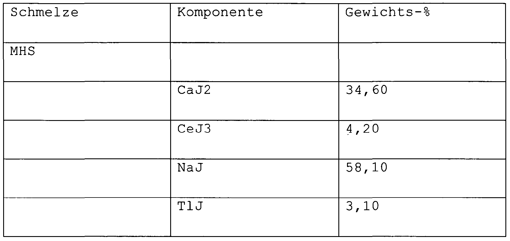
- Tab. 2b shows fillings for discharge vessels with bulbous form. from. 3 shows the composition of a melt for Tab. 2a.
- Tab. 4 shows fillings for elliptical discharge vessels.
- Table 5 shows the melt compositions for the fillings from Tab. 4
- FIG. 3 shows illustrations of a further exemplary embodiment of a lamp in two views rotated through 90 ° (FIGS. 3 and 3 b).
- FIG. 4 shows a lamp with an elongate rounded discharge vessel in an evacuated outer bulb.
- Figure 5 shows two rotated by 90 ° side views of a lamp with Zundst Shape 20 made of Pt, which is guided along the outside of the discharge vessel. It is parallel to the axis and extends from the first end 21 via the discharge volume 22 to the second end 23. Capillaries 24 are still attached to the end.
Landscapes
- Discharge Lamp (AREA)
Abstract
Description




Claims
Priority Applications (3)
| Application Number | Priority Date | Filing Date | Title |
|---|---|---|---|
| DE112010000668T DE112010000668A5 (de) | 2009-02-20 | 2010-02-02 | Hochdruckentladungslampe |
| CN2010800084098A CN102326225A (zh) | 2009-02-20 | 2010-02-02 | 高压放电灯 |
| US13/146,409 US20110279031A1 (en) | 2009-02-20 | 2010-02-02 | High pressure discharge lamp |
Applications Claiming Priority (2)
| Application Number | Priority Date | Filing Date | Title |
|---|---|---|---|
| DE102009009890.9 | 2009-02-20 | ||
| DE102009009890A DE102009009890A1 (de) | 2009-02-20 | 2009-02-20 | Hochdruckentladungslampe |
Publications (1)
| Publication Number | Publication Date |
|---|---|
| WO2010094557A1 true WO2010094557A1 (de) | 2010-08-26 |
Family
ID=42017241
Family Applications (1)
| Application Number | Title | Priority Date | Filing Date |
|---|---|---|---|
| PCT/EP2010/051223 Ceased WO2010094557A1 (de) | 2009-02-20 | 2010-02-02 | Hochdruckentladungslampe |
Country Status (4)
| Country | Link |
|---|---|
| US (1) | US20110279031A1 (de) |
| CN (1) | CN102326225A (de) |
| DE (2) | DE102009009890A1 (de) |
| WO (1) | WO2010094557A1 (de) |
Families Citing this family (1)
| Publication number | Priority date | Publication date | Assignee | Title |
|---|---|---|---|---|
| JP2013232311A (ja) * | 2012-04-27 | 2013-11-14 | Iwasaki Electric Co Ltd | メタルハライドランプ |
Citations (6)
| Publication number | Priority date | Publication date | Assignee | Title |
|---|---|---|---|---|
| US3530327A (en) * | 1968-03-11 | 1970-09-22 | Westinghouse Electric Corp | Metal halide discharge lamps with rare-earth metal oxide used as electrode emission material |
| DE2519377A1 (de) | 1975-04-30 | 1976-11-11 | Patra Patent Treuhand | Quecksilberdampf-hochdruckentladungslampe |
| EP0057093A1 (de) | 1981-01-23 | 1982-08-04 | North American Philips Lighting Corporation | Entladungslampen hoher Intensität |
| DE19731168A1 (de) * | 1997-07-21 | 1999-01-28 | Patent Treuhand Ges Fuer Elektrische Gluehlampen Mbh | Beleuchtungssystem |
| US20050042967A1 (en) * | 2001-05-08 | 2005-02-24 | Jackson Andrew D. | Coil antenna/protection for ceramic metal halide lamps |
| US20070120458A1 (en) * | 2005-11-30 | 2007-05-31 | Mohamed Rahmane | Mercury-free metal halide discharge lamp |
Family Cites Families (4)
| Publication number | Priority date | Publication date | Assignee | Title |
|---|---|---|---|---|
| DE10254969A1 (de) * | 2002-11-26 | 2004-06-03 | Philips Intellectual Property & Standards Gmbh | Hochdruckentladungslampe mit Quecksilberchlorid bei begrenztem Chlorgehalt |
| CN101248509A (zh) * | 2005-04-08 | 2008-08-20 | 皇家飞利浦电子股份有限公司 | 高压放电灯 |
| EP1869694A2 (de) * | 2005-04-08 | 2007-12-26 | Koninklijke Philips Electronics N.V. | Hochdruckentladungslampe |
| US7868553B2 (en) * | 2007-12-06 | 2011-01-11 | General Electric Company | Metal halide lamp including a source of available oxygen |
-
2009
- 2009-02-20 DE DE102009009890A patent/DE102009009890A1/de not_active Withdrawn
-
2010
- 2010-02-02 WO PCT/EP2010/051223 patent/WO2010094557A1/de not_active Ceased
- 2010-02-02 DE DE112010000668T patent/DE112010000668A5/de not_active Withdrawn
- 2010-02-02 US US13/146,409 patent/US20110279031A1/en not_active Abandoned
- 2010-02-02 CN CN2010800084098A patent/CN102326225A/zh active Pending
Patent Citations (6)
| Publication number | Priority date | Publication date | Assignee | Title |
|---|---|---|---|---|
| US3530327A (en) * | 1968-03-11 | 1970-09-22 | Westinghouse Electric Corp | Metal halide discharge lamps with rare-earth metal oxide used as electrode emission material |
| DE2519377A1 (de) | 1975-04-30 | 1976-11-11 | Patra Patent Treuhand | Quecksilberdampf-hochdruckentladungslampe |
| EP0057093A1 (de) | 1981-01-23 | 1982-08-04 | North American Philips Lighting Corporation | Entladungslampen hoher Intensität |
| DE19731168A1 (de) * | 1997-07-21 | 1999-01-28 | Patent Treuhand Ges Fuer Elektrische Gluehlampen Mbh | Beleuchtungssystem |
| US20050042967A1 (en) * | 2001-05-08 | 2005-02-24 | Jackson Andrew D. | Coil antenna/protection for ceramic metal halide lamps |
| US20070120458A1 (en) * | 2005-11-30 | 2007-05-31 | Mohamed Rahmane | Mercury-free metal halide discharge lamp |
Also Published As
| Publication number | Publication date |
|---|---|
| DE102009009890A1 (de) | 2010-08-26 |
| DE112010000668A5 (de) | 2012-10-31 |
| US20110279031A1 (en) | 2011-11-17 |
| CN102326225A (zh) | 2012-01-18 |
Similar Documents
| Publication | Publication Date | Title |
|---|---|---|
| DE69303079T2 (de) | Hochdrucknatriumlampe | |
| EP0834905B1 (de) | Natriumhochdrucklampe kleiner Leistung | |
| EP1465237B1 (de) | Hochdruckentladungslampe für Fahrzeugscheinwerfer | |
| EP0841686B1 (de) | Metallhalogenid-Hochdruckentladungslampe | |
| DE10291427B4 (de) | Halogen-Metalldampflampe für einen Kraftfahrzeugscheinwerfer | |
| DE2815014C2 (de) | Hochdrucknatriumdampfentladungslampe | |
| EP0453893B1 (de) | Hochdruckentladungslampe | |
| DE2161173B2 (de) | Oxydelektrode für elektrische Hochleistungs-Gasentladungslampen | |
| EP1011126A2 (de) | Metallhalogenidlampe | |
| DE2746671A1 (de) | Elektrische hochdruckentladungslampe | |
| DE19937312A1 (de) | Quecksilberfreie Metallhalogenidlampe | |
| DE2710179A1 (de) | Hochdrucknatriumdampflampe mit niedriger zuendspannung | |
| EP2499657B1 (de) | Quecksilberfreie hochdruckentladungslampe mit reduziertem zinkhalogenidanteil | |
| DE2422576C3 (de) | Quecksilberdampflampe | |
| EP2347430B1 (de) | Quecksilberfreie entladungslampe | |
| DE3110872C2 (de) | Alkalimetalldampflampe | |
| WO2010094557A1 (de) | Hochdruckentladungslampe | |
| DE2201831A1 (de) | Bogenentladungsvorrichtung | |
| EP1754245A2 (de) | Hochdruckentladungslampe | |
| DE69327275T2 (de) | Metall iodid lampe | |
| DE102004043247B4 (de) | Elektrode für Hochdruckentladungslampen sowie Hochdruckentladungslampe mit derartigen Elektroden | |
| DE202010018034U1 (de) | Hochdruckentladungslampe | |
| DE3307197C2 (de) | ||
| DE3137076A1 (de) | Hochdruck-entladungslampe | |
| WO2009109566A1 (de) | Wolframelektrode für hochdruckentladungslampen und hochdruckentladungslampe mit einer wolframelektrode |
Legal Events
| Date | Code | Title | Description |
|---|---|---|---|
| WWE | Wipo information: entry into national phase |
Ref document number: 201080008409.8 Country of ref document: CN |
|
| 121 | Ep: the epo has been informed by wipo that ep was designated in this application |
Ref document number: 10702665 Country of ref document: EP Kind code of ref document: A1 |
|
| WWE | Wipo information: entry into national phase |
Ref document number: 13146409 Country of ref document: US |
|
| WWE | Wipo information: entry into national phase |
Ref document number: 112010000668 Country of ref document: DE Ref document number: 1120100006687 Country of ref document: DE |
|
| 122 | Ep: pct application non-entry in european phase |
Ref document number: 10702665 Country of ref document: EP Kind code of ref document: A1 |
|
| REG | Reference to national code |
Ref country code: DE Ref legal event code: R225 Ref document number: 112010000668 Country of ref document: DE Effective date: 20121031 |