WO2010092842A1 - 圧電体膜を用いた振動ジャイロ及びその製造方法 - Google Patents
圧電体膜を用いた振動ジャイロ及びその製造方法 Download PDFInfo
- Publication number
- WO2010092842A1 WO2010092842A1 PCT/JP2010/050063 JP2010050063W WO2010092842A1 WO 2010092842 A1 WO2010092842 A1 WO 2010092842A1 JP 2010050063 W JP2010050063 W JP 2010050063W WO 2010092842 A1 WO2010092842 A1 WO 2010092842A1
- Authority
- WO
- WIPO (PCT)
- Prior art keywords
- ring
- vibration
- electrodes
- metal film
- electrode
- Prior art date
- Legal status (The legal status is an assumption and is not a legal conclusion. Google has not performed a legal analysis and makes no representation as to the accuracy of the status listed.)
- Ceased
Links
Images













Classifications
-
- G—PHYSICS
- G01—MEASURING; TESTING
- G01C—MEASURING DISTANCES, LEVELS OR BEARINGS; SURVEYING; NAVIGATION; GYROSCOPIC INSTRUMENTS; PHOTOGRAMMETRY OR VIDEOGRAMMETRY
- G01C19/00—Gyroscopes; Turn-sensitive devices using vibrating masses; Turn-sensitive devices without moving masses; Measuring angular rate using gyroscopic effects
- G01C19/56—Turn-sensitive devices using vibrating masses, e.g. vibratory angular rate sensors based on Coriolis forces
- G01C19/567—Turn-sensitive devices using vibrating masses, e.g. vibratory angular rate sensors based on Coriolis forces using the phase shift of a vibration node or antinode
- G01C19/5677—Turn-sensitive devices using vibrating masses, e.g. vibratory angular rate sensors based on Coriolis forces using the phase shift of a vibration node or antinode of essentially two-dimensional [2D] vibrators, e.g. ring-shaped vibrators
Definitions
- the present invention relates to a vibrating gyroscope using a piezoelectric film and a method of manufacturing the vibrating gyroscope.
- the size reduction of the gyro itself is also an important issue, as the size of various devices on which the gyro is mounted is becoming smaller and smaller.
- it is necessary to significantly increase the processing accuracy of each member constituting the gyro.
- it is a strong demand in the industry to further improve the performance as a gyro, in other words, the detection accuracy of angular velocity.
- the structure of the gyro shown in Patent Document 2 does not satisfy the demand for miniaturization and high performance in recent years.
- the present invention greatly contributes to the miniaturization and high performance of a vibrating gyroscope using a piezoelectric film, that is, a gyroscope or an angular velocity sensor using vibration by solving the above-mentioned technical problems.
- the inventors first adopted, as a basic structure, a ring-shaped vibrating gyroscope which is considered to have a relatively small influence on disturbance among the above-mentioned technical problems.
- the inventors intensively studied the structure for solving the above-mentioned respective technical problems by making the piezoelectric film bear the detection of the secondary vibration formed by the excitation of the primary vibration and the Coriolis force.
- One vibrating gyroscope of the present invention is placed on or above a ring-shaped vibrating body having a uniform plane, a leg portion for flexibly supporting the ring-shaped vibrating body, and the ring-shaped vibrating body.
- a plurality of electrodes formed of at least one of an upper metal film and a lower metal film sandwiching the piezoelectric film in the thickness direction are provided.
- N is a natural number of 2 or more
- the plurality of electrodes mentioned above excite the primary vibration of the ring-shaped vibrating body in the vibration mode of cos N ⁇ when N is a natural number of 2 or more.
- a group of drive electrodes arranged at different angles, and at an angle separated by (90 / N) ° clockwise and / or counterclockwise from any of the aforementioned drive electrodes, and on the aforementioned ring-shaped vibrating body A detection electrode for detecting secondary vibration generated when an angular velocity is given, and an angle away from (90 / N) ° clockwise or counterclockwise from any of the above-mentioned drive electrodes or from the above-mentioned detection electrode ( And a suppression electrode disposed at an angle separated by 180 / N) ° and suppressing the secondary vibration based on the voltage signal from the detection electrode described above.
- the above-mentioned drive electrode, the above-mentioned detection electrode, and the above-mentioned suppression electrode have a region from the outer peripheral edge of the above-mentioned ring-shaped vibrating body to the vicinity of the outer peripheral edge and / or the vicinity of the inner peripheral edge It is arranged in the area up to.
- a voltage is applied to the piezoelectric element in the above-described specific region on a plane of the ring-shaped vibrating body, and a voltage signal generated by distortion of the piezoelectric element is picked up. Since the electrodes are formed, excitation of the primary vibration and detection of the secondary vibration can be performed as a uniaxial angular velocity sensor.
- the primary vibration is excited in the same plane as the plane on which the piezoelectric element is disposed on the ring-shaped vibrating body without forming the piezoelectric element on the side surface of the ring-shaped vibrating body, and the ring-shaped vibration Since the structure for controlling the movement of the body is provided, it is possible to process the electrode and the ring-shaped vibrating body with high accuracy using dry process technology. Further, in this vibrating gyroscope, by disposing the piezoelectric element in the above-described unique region, there is a degree of freedom that can be applied to the vibrating mode of cos N ⁇ in the case where N is a natural number of 2 or more.
- the piezoelectric element in the above specific region, the driving force, the detection capability, and the suppression force of the vibrating gyroscope using in-plane vibration are exhibited. Furthermore, since this vibrating gyroscope includes the suppression electrode that suppresses the secondary vibration based on the voltage signal from the detection electrode that detects the secondary vibration, the ratio of the strength of the output signal to the noise from the outside, ie, , The S / N ratio increases dramatically.
- a plurality of examples of the vibration mode of cos N ⁇ are described in, for example, Japanese Patent Application Publication No. 2005-529306 or Japanese Patent Application No. 2007-209014 which is a patent application filed by the applicant of the present application.
- “flexible” means “to the extent that the vibrating body can vibrate”.
- the expression “an angle away from the reference electrode” is used to describe the arrangement of the electrodes. The angle here is the value of the azimuth of each electrode when the azimuth of the reference electrode is 0 degree.
- the azimuth angle of each electrode is an arbitrary point taken on the circumference of the ring-shaped vibrating body or in the central part of the ring (for example, when the ring-shaped vibrating body is circular, it is, for example, the center of the circle) The center can be referred to as the "reference point") and the azimuth angle of a straight line from the electrode to the electrode.
- This straight line may be any straight line passing through each electrode, and typically passes through the graphic center, the center of gravity, or any vertex of each electrode and the reference point described above It can be straight.
- an electrode arranged at an angle of 30 ° from the reference drive electrode means that the center of the electrode and the center of the reference drive electrode form an angle of 30 ° with respect to the azimuth of the reference electrode.
- An electrode in an arrangement like this is also noted.
- the notation of the angle describes clockwise direction as the direction in which the angle increases, but even if the direction in which the angle increases is defined counterclockwise, as long as the defined angle conditions are satisfied. The notation of the angle is within the scope of the present invention.
- Another vibration gyro comprises a ring-shaped vibrating body having a uniform plane, a leg portion for flexibly supporting the ring-shaped vibrating body, and a ring-shaped vibrating body disposed on or above the ring-shaped vibrating body. And a plurality of electrodes formed of at least one of an upper metal film and a lower metal film sandwiching the piezoelectric film in the thickness direction.
- N is a natural number of 2 or more
- the plurality of electrodes mentioned above excite the primary vibration of the ring-shaped vibrating body in the vibration mode of cos N ⁇ when N is a natural number of 2 or more.
- each of the drive electrodes described above, each monitor electrode described above, the detection electrode described above, and the suppression electrode described above are in the region from the outer peripheral edge of the above-mentioned ring-shaped vibrator to the vicinity of the outer peripheral edge Or it is arrange
- a voltage is applied to the piezoelectric element and a voltage signal generated by distortion of the piezoelectric element is picked up on the flat surface of the ring-shaped vibrating body and in the above specific region. Since the electrodes are formed, excitation of the primary vibration and detection of the secondary vibration can be performed as a uniaxial angular velocity sensor.
- the primary vibration is excited in the same plane as the plane on which the piezoelectric element is disposed on the ring-shaped vibrating body without forming the piezoelectric element on the side surface of the ring-shaped vibrating body, and the ring-shaped vibration Since the structure for controlling the movement of the body is provided, it is possible to process the electrode and the ring-shaped vibrating body with high accuracy using dry process technology. Further, in this vibrating gyroscope, by disposing the piezoelectric element in the above-described unique region, there is a degree of freedom that can be applied to the vibrating mode of cos N ⁇ in the case where N is a natural number of 2 or more.
- the vibration gyro includes the suppression electrode that suppresses the secondary vibration based on the voltage signal from the detection electrode that detects the secondary vibration, the S / N ratio is dramatically increased.
- Another vibration gyro comprises a ring-shaped vibrating body having a uniform plane, a leg portion for flexibly supporting the ring-shaped vibrating body, and a ring-shaped vibrating body disposed on or above the ring-shaped vibrating body. And a plurality of electrodes formed of at least one of an upper metal film and a lower metal film sandwiching the piezoelectric film in the thickness direction.
- N is a natural number of 2 or more
- the plurality of electrodes mentioned above excite the primary vibration of the ring-shaped vibrating body in the vibration mode of cos N ⁇ when N is a natural number of 2 or more.
- each of the drive electrodes described above, the detection electrode described above, and the suppression electrode described above have a region from the outer peripheral edge of the ring-shaped vibrator to the vicinity of the outer peripheral edge and / or the inner peripheral edge It is arranged in the area up to the neighborhood of.
- the vibration axis means an orientation such that the amplitude of the described vibration is the largest, and is indicated by the direction on the ring-shaped vibrating body.
- a voltage is applied to the piezoelectric element and a voltage signal generated by distortion of the piezoelectric element is picked up on the flat surface of the ring-shaped vibrating body and in the above specific region. Since the electrodes are formed, excitation of the primary vibration and detection of the secondary vibration can be performed as a uniaxial angular velocity sensor.
- the primary vibration is excited in the same plane as the plane on which the piezoelectric element is disposed on the ring-shaped vibrating body without forming the piezoelectric element on the side surface of the ring-shaped vibrating body, and the ring-shaped vibration Since the structure for controlling the movement of the body is provided, it is possible to process the electrode and the ring-shaped vibrating body with high accuracy using dry process technology. Further, in this vibrating gyroscope, by disposing the piezoelectric element in the above-described unique region, there is a degree of freedom that can be applied to the vibrating mode of cos N ⁇ in the case where N is a natural number of 2 or more.
- the vibration gyro includes the suppression electrode that suppresses the secondary vibration based on the voltage signal from the detection electrode that detects the secondary vibration, the S / N ratio is dramatically increased.
- a step of uniformly forming an insulating film on a silicon substrate, a step of uniformly forming a lower metal film on the insulating film, and a lower layer thereof A step of uniformly forming a piezoelectric film on a metal film, a step of uniformly forming an upper metal film on the piezoelectric film, and a step of patterning a first resist film on the upper metal film And dry etching the upper layer metal film to expose the above-mentioned piezoelectric film, and patterning a second resist film on the upper layer metal film and the piezoelectric film.
- the lower resist film, the lower metal film, and the insulation thereof are used with the second resist film, the upper metal film, or the piezoelectric film described above as an etching mask.
- the film and the silicon substrate are dry-etched to flexibly support the ring-shaped vibrating body and the ring-shaped vibrating body, and a leg portion having a fixed end, and cos N ⁇ when N is a natural number of 2 or more.
- the vibrating gyroscope since high-precision processing can be performed by the dry process technology, it is possible to form the piezoelectric element in a specific region on a plane provided in the ring-shaped vibrating body. As a result, without arranging the piezoelectric element on the side surface of the ring-shaped vibrating body, only the piezoelectric element on the plane can play a role of exciting primary vibration and detecting secondary vibration as a uniaxial angular velocity sensor. A vibratory gyroscope with a dramatically improved S / N ratio is manufactured.
- the ring-shaped vibrating body is formed of a silicon substrate, a known silicon trench etching technique having a sufficiently high selection ratio with the resist film can be applied. Even if the resist film disappears, the upper metal film or the piezoelectric film under the film has a sufficient selectivity to serve as a mask in etching of silicon.
- another method of manufacturing a vibrating gyroscope according to the present invention comprises the steps of: forming an insulating film uniformly on a silicon substrate; forming a lower metal film uniformly on the insulating film; Forming a piezoelectric film uniformly on the lower metal film, forming an upper metal film uniformly on the piezoelectric film, and patterning a first resist film on the upper metal film Using the first resist film as an etching mask, and dry etching the upper metal film and the piezoelectric film to expose the lower metal film, and covering the upper metal film and the lower metal film. And patterning the second resist film.
- the insulating film of the second resist film described above, the upper metal film described above, or the lower metal film described above is used as an etching mask
- N is a natural number of 2 or more
- This manufacturing method of the vibrating gyroscope also enables high-precision processing by the dry process technology, and therefore, it is possible to form the piezoelectric element in a specific region on the plane of the ring-shaped vibrating body. As a result, without arranging the piezoelectric element on the side surface of the ring-shaped vibrating body, only the piezoelectric element on the plane can play a role of exciting primary vibration and detecting secondary vibration as a uniaxial angular velocity sensor. A vibratory gyroscope with a dramatically improved S / N ratio is manufactured.
- the primary vibration is excited in the same plane as the plane on which the piezoelectric element on the ring-shaped vibrating body is disposed, without forming the piezoelectric element on the side surface of the ring-shaped vibrating body
- the movement of the ring oscillator can also be controlled.
- this vibration gyro has degrees of freedom applicable to the vibration mode of cos N ⁇ when N is a natural number of 2 or more by arranging the piezoelectric element in a specific region. That is, by disposing the piezoelectric element in the above specific region, the driving force, the detection capability, and the suppression force of the vibrating gyroscope using in-plane vibration are exhibited.
- a piezoelectric element can be formed in a specific region on a plane provided in a ring-shaped vibrator. It becomes possible.
- a piezoelectric element on the side surface of the ring-shaped vibrating body without arranging the piezoelectric element on the side surface of the ring-shaped vibrating body, only the piezoelectric element on the plane can play a role of exciting primary vibration and detecting secondary vibration as a uniaxial angular velocity sensor.
- a vibratory gyroscope with a dramatically improved S / N ratio is manufactured.
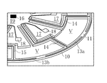
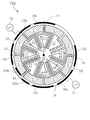
- FIG. 1 is a front view of a structure that plays a central role in a ring-shaped vibrating gyroscope in an embodiment of the present invention. It is a perspective view of a structure shown in FIG. It is an enlarged view of a part (W part) of FIG. 2A.
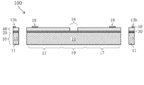
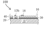
- FIG. 2 is a cross-sectional view taken along the line XX in FIG. It is sectional drawing which shows the process of the manufacturing process of a part of ring-shaped vibrating gyroscope in one embodiment of this invention. It is sectional drawing which shows the process of the manufacturing process of a part of ring-shaped vibrating gyroscope in one embodiment of this invention.
- FIG. 1 It is sectional drawing which shows the process of the manufacturing process of a part of ring-shaped vibrating gyroscope in one embodiment of this invention. It is sectional drawing which shows the process of the manufacturing process of a part of ring-shaped vibrating gyroscope in one embodiment of this invention. It is sectional drawing which shows the process of the manufacturing process of a part of ring-shaped vibrating gyroscope in one embodiment of this invention. It is sectional drawing which shows the process of the manufacturing process of a part of ring-shaped vibrating gyroscope in one embodiment of this invention. It is a front view of the structure which plays a central role of the ring-shaped vibrating gyroscope in other embodiment of this invention.
- FIG. 1 It is a front view of the structure which plays a central role of the ring-shaped vibrating gyroscope in other embodiment of this invention.
- FIG. 6 is a YY cross-sectional view of FIG. 5; It is a front view of the structure which plays a central role of the ring-shaped vibrating gyroscope in other embodiment of this invention. It is ZZ sectional drawing of FIG.
- FIG. 1 is a front view of a structure that plays a central role in a ring-shaped vibrating gyroscope in an embodiment of the present invention.
- FIG. 1 is a front view of a structure that plays a central role in a ring-shaped vibrating gyroscope in an embodiment of the present invention. It is a front view of the structure which plays a central role of the ring-shaped vibrating gyroscope in other embodiment of this invention.
- FIG. 1 is a front view of a structure that plays a central role in the ring-shaped vibrating gyroscope 100 in the present embodiment.
- 2A is a perspective view of the structure shown in FIG. 1, and
- FIG. 2B is an enlarged view of a part (W part) of FIG. 2A.
- FIG. 3 is a cross-sectional view taken along the line XX in FIG.
- the ring-shaped vibrating gyroscope 100 of this embodiment is roughly classified into three regions.
- the first region is provided with a silicon oxide film 20 on the upper surface (hereinafter referred to as the upper surface) of the ring-shaped vibrating member 11 formed from the silicon substrate 10, and further the piezoelectric film 40 is a lower metal
- This is a region provided with a plurality of electrodes 13a to 13d formed by being sandwiched between the film 30 and the upper metal film 50.
- the outer end of the upper metal film 50 constituting the plurality of electrodes 13a to 13d is formed about 1 ⁇ m inward from the outer peripheral edge of the ring-shaped vibrating body 11 having a ring-shaped flat about 40 ⁇ m wide.
- the width is about 18 ⁇ m.
- the upper metal film 50 is formed outside the line connecting the centers between both ends of the width of the ring-shaped plane which is the upper surface of the ring-shaped vibrating body 11 (hereinafter simply referred to as the center line).
- the primary vibration of the ring-shaped vibrating gyroscope 100 is excited in the vibration mode of cos 2 ⁇ . Therefore, the breakdown of the plurality of electrodes 13a to 13d is as follows (a) to (d).
- A Two drive electrodes 13a and 13a arranged at an angle of 180 ° in the circumferential direction
- B Two monitor electrodes 13c, 13c arranged at an angle of 90 ° in the circumferential direction from the drive electrodes 13a, 13a
- C Detection electrodes 13b and 13b for detecting secondary vibration generated when angular velocity is given to ring-shaped vibrating gyroscope 100
- D Suppression electrodes 13d and 13d for suppressing secondary vibration based on the voltage signal from the detection electrode described above
- the detection electrodes 13 b and 13 b are disposed at an angle of 45 ° in the circumferential direction and clockwise from the drive electrodes 13 a and 13 a.
- the suppression electrodes 13d and 13d are circumferentially separated from the detection electrode by 90 °, in other words, circumferentially separated from the drive electrodes 13a and 13a by 45 ° counterclockwise. Be placed.
- the detection electrodes 13b and 13b and the suppression electrodes 13d and 13d have an angular velocity at the ring-shaped vibrating member 11 inclined 45 ° with respect to the vibration axis of the primary vibration generated by the drive electrodes 13a and 13a. Is placed on the vibration axis of the secondary vibration that occurs when given.
- the thickness of the lower metal film 30 and the upper metal film 50 is 100 nm, and the thickness of the piezoelectric film 40 is 3 ⁇ m. Also, the thickness of the silicon substrate 10 is 100 ⁇ m.
- the hatched area indicated by V in FIG. 1 or the area indicated by V in FIG. 2B is a space or an air gap where there is no structure constituting the ring-shaped vibrating gyroscope 100, in order to make the drawing easy to understand. Are provided for the sake of convenience.
- the second region is the leg portions 15 to 15 connected to a part of the ring-shaped vibrating body 11.
- the leg portions 15 to 15 are also formed of the silicon substrate 10. Further, on the leg portions 15,..., 15, the above-mentioned silicon oxide film 20, lower metal film 30, and piezoelectric film 40 which are continuous with those on the ring-shaped vibrating body 11 are leg portions 15,.
- ⁇ ⁇ Are formed on the entire top surface of 15 Further, on the center line of the upper surface of the piezoelectric film 40, an upper metal film 50 which is a lead electrode 14,..., 14 with a width of about 8 ⁇ m is formed.
- the third region is a fixed end for an electrode pad provided with a support 19 formed from the silicon substrate 10 connected to the above-mentioned legs 15 to 15 and electrode pads 18 to 18. 17, ..., 17.
- the support 19 is connected to the package portion of the ring-shaped vibrating gyroscope 100 (not shown) and plays a role as a fixed end.
- the ring-shaped vibrating gyroscope 100 of the present embodiment is provided with electrode pad fixed ends 17,..., 17 as fixed ends other than the support column 19. Since the electrode pad fixed ends 17,..., 17 are connected only to the support 19 and the above-mentioned package portion, they do not substantially inhibit the movement of the ring-shaped vibrating body 11. Further, as shown in FIG.
- the leg parts 15 On the upper surfaces of the support column 19 and the electrode pad fixed ends 17... 17, except for the fixed potential electrode 16 which is a ground electrode, the leg parts 15.
- the silicon oxide film 20, the lower metal film 30, and the piezoelectric film 40 described above which are continuous with those above are formed.
- the lower metal film 30 formed on the silicon oxide film 20 plays a role of the fixed potential electrode 16.
- the electrodes 14, ..., 14 and the electrode pads 18, ..., 18 are formed.
- FIGS. 4A to 4F are cross-sectional views corresponding to a partial range in FIG.
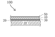
- a silicon oxide film 20, a lower metal film 30, a piezoelectric film 40, and an upper metal film 50 are stacked on a silicon substrate 10.
- Each film described above is formed by a known film forming means.
- the silicon oxide film 20 is a thermal oxide film by a known means.
- the lower metal film 30, the piezoelectric film 40, and the upper metal film 50 are all formed by a known sputtering method.
- membranes is not limited to the above-mentioned example, It can form also by another well-known means.
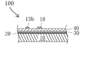
- the upper metal film 50 shown in FIG. 4B is formed by performing dry etching based on the pattern formed by the photolithography technique. Ru.
- dry etching of the upper metal film 50 was performed under known reactive ion etching (RIE) conditions using argon (Ar) or a mixed gas of argon (Ar) and oxygen (O 2 ).
- RIE reactive ion etching
- the piezoelectric film 40 is dry etched based on the resist film patterned by the photolithography technique.
- the dry etching of the piezoelectric film 40 according to the present embodiment can be performed by using a known reactive ion etching using a mixed gas of argon (Ar) and C 2 F 6 gas or a mixed gas of argon (Ar), C 2 F 6 gas, and CHF 3 gas (RIE) performed by conditions.
- a part of the lower metal film 30 is etched.
- dry etching is performed again using the resist film patterned by photolithography so that the fixed potential electrode 16 using the lower metal film 30 is formed.
- the fixed potential electrode 16 is used as a ground electrode.
- the thickness of this resist film is about 4 ⁇ m. Is formed.
- the selection ratio of the etching rate to the etchant used for the silicon substrate 10 works advantageously, so that the lower metal film is formed by the above-mentioned etching. The performance of 30 is virtually unaffected.
- the silicon oxide film 20 and the silicon substrate 10 are dry etched using the resist film for etching the lower metal film 30.
- the dry etching of the silicon oxide film 20 of the present embodiment was performed under known reactive ion etching (RIE) conditions using argon (Ar) or a mixed gas of argon (Ar) and oxygen (O 2 ). Further, as a condition of the dry etching of the silicon substrate 10 of the present embodiment, a known silicon trench etching technique is applied. Here, the silicon substrate 10 is etched through.
- RIE reactive ion etching
- a protective substrate for preventing the stage on which the silicon substrate 10 is mounted is exposed to plasma during penetration is adhered to the lower layer of the silicon substrate 10 by grease or the like excellent in heat conductivity.
- the dry etching technique described in Japanese Patent Application Laid-Open No. 2002-158214 is It is a preferred embodiment to be employed.
- the central structure of the ring-shaped vibrating gyroscope 100 is formed by etching the silicon substrate 10 and the respective films stacked on the silicon substrate 10, the step of containing in a package by known means; By passing through the wiring process, the ring-shaped vibrating gyroscope 100 is formed.
- each electrode provided in the ring-shaped vibrating gyroscope 100 will be described.
- the primary vibration of the vibration mode of cos 2 ⁇ is excited. Since the fixed potential electrode 16 is grounded, the lower layer electrode film 30 formed continuously with the fixed potential electrode 16 is uniformly at 0V.
- an alternating voltage of 1VP-0 is applied to the two drive electrodes 13a, 13a.
- the piezoelectric film 40 expands and contracts to excite primary vibration.
- the upper metal film 50 is formed outside the center line of the upper surface of the ring-shaped vibrating member 11, the upper metal film 50 is not formed on the side surface of the ring-shaped vibrating member 11. It becomes possible to convert the stretching movement into the primary vibration of the ring-shaped vibrating body 11.
- monitor electrodes 13 c and 13 c shown in FIG. 1 detect the amplitude and resonance frequency of the above-mentioned primary vibration, and transmit a signal to a known feedback control circuit (not shown).
- the feedback control circuit controls so that the frequency of the AC voltage applied to the drive electrodes 13a and 13a matches the natural frequency of the ring-shaped vibrating body 11, and the amplitude of the ring-shaped vibrating body 11 has a certain value. It controls using the signal of the monitor electrodes 13c and 13c so that it may become. As a result, the ring-shaped vibrating body 11 maintains a constant vibration.
- This secondary vibration is detected by the two detection electrodes 13b and 13b.
- the ring-shaped vibrating gyroscope 100 of the present embodiment in other words, to zero the value of the voltage signal.
- And feedback control circuits 61 and 62 for instructing or controlling application of a specific voltage to the suppression electrodes 13d and 13d. Note that this particular voltage is used as a result output as a vibrating gyroscope.
- the ring-shaped vibrating gyroscope 100 can generate the secondary vibration of the ring-shaped vibrating body 11
- the performance as a vibrating gyroscope can be exhibited with almost no vibration.
- the ring-shaped vibrating gyroscope 100 of the present embodiment is extremely excellent in noise performance as compared with a vibrating gyroscope in which the suppression electrodes 13 d and 13 d and the feedback control circuits 61 and 62 are not provided.
- the ring-shaped vibrating gyroscope 100 according to the present embodiment is compared with an example (a vibrating gyroscope according to the first embodiment) described in PCT / JP2008 / 071372 previously proposed by the present applicant.
- the magnitude of noise in the low frequency region is less than half. Therefore, the S / N ratio can be dramatically improved without sacrificing responsiveness.
- a well-known feedback control circuit can be applied to the above-mentioned feedback control circuits 61 and 62.
- the detection electrodes 13b and 13b are disposed at 180 ° apart in the circumferential direction.
- the expansion and contraction of the piezoelectric film 40 on the leg portions connected to the detection electrodes 13b and 13b are reversed even if they occur.
- the positive and negative of the electric signal of each detection electrode 13b become reverse.
- the electrical signals will cancel one another. For this reason, the influence of the vibration of the rocking mode on the operation of the ring-shaped vibrating gyroscope 100 is substantially eliminated.
- the ring-shaped vibrating gyroscope 100 includes the two detection electrodes 13b and 13b and the two suppression electrodes 13d and 13d, whereby the detection capability of the secondary vibration is enhanced, and the vibration of the locking mode is generated. Impact resistance to external impact that excites
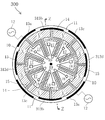
- FIG. 5 is a front view of a structure that plays a central role in another ring-shaped vibrating gyroscope 200 in the present embodiment.
- 6 is a cross-sectional view taken along line YY of FIG.
- the ring-shaped vibrating gyroscope 200 of the present embodiment has the same configuration as the ring-shaped vibrating gyroscope 100 of the first embodiment except for the piezoelectric film 40 and the upper metal film 50 in the first embodiment.
- the manufacturing method is the same as that of the first embodiment except for a part.
- the vibration mode of the present embodiment is a vibration mode of cos 2 ⁇ , as in the first embodiment. Therefore, the description overlapping with the first embodiment may be omitted.
- the feedback control circuits 61 and 62 in FIG. 1 are omitted for the sake of convenience in order to make the drawing easy to see.
- the ring-shaped vibrating gyroscope 200 of the present embodiment includes suppression electrodes 213d and 213d instead of the suppression electrodes 13d and 13d of the first embodiment.
- the outer end portions of the upper metal film 50 of the suppression electrodes 213d and 213d of the present embodiment are formed about 1 ⁇ m inward from the inner peripheral edge of the ring-shaped vibrating body 11, and the width thereof is about 18 ⁇ m.
- the upper layer metal films 50 are formed inside the center line of the ring-shaped flat surface of the ring-shaped vibrating body 11.
- the piezoelectric film 40 is etched in conformity with the area where the upper metal film 50 is substantially formed. For this reason, since the alternating voltage applied to the upper metal film 50 is applied only vertically downward without being affected by the region in which the lower metal film 30 is formed, undesired expansion and contraction of the piezoelectric film 40 and an electric signal are generated. Can be prevented.
- the residual resist film on the upper layer metal film 50 or the metal film 50 itself is used as an etching mask, and subsequently, under the same conditions as the first embodiment.
- the above-described piezoelectric film 40 is formed by performing dry etching. Further, as shown in FIG.
- the piezoelectric film 40 is etched in an inclined manner (for example, an inclination angle of 75 °).
- the piezoelectric film 40 having a steep slope as shown in FIG. 6 is substantially invisible as compared to other regions in the front view of the ring-shaped vibrating gyroscope 200 shown in FIG. Handled.
- the ring-shaped vibrating gyroscope 200 when an angular velocity around the vertical axis (direction perpendicular to the paper surface) of the ring-shaped vibrating gyroscope 200 is added to the ring-shaped vibrating gyroscope 200 in which the primary vibration similar to the first embodiment is excited, The next vibration is detected by the two detection electrodes 13b and 13b.
- the ring-shaped vibrating gyroscope 200 according to the present embodiment also causes a specific voltage for reducing or canceling the voltage signal related to the secondary vibration detected by the detection electrodes 13b and 13b described above with respect to the suppression electrodes 213d and 213d.
- a feedback control circuit (not shown) is provided to direct or control to provide. Note that this particular voltage is used as a result output as a vibrating gyroscope.
- the ring-shaped vibrating gyroscope 200 almost vibrates the secondary vibration of the ring-shaped vibrating body 11 It is possible to demonstrate the performance as a vibrating gyroscope which is extremely excellent in response and detection ability without causing
- the upper metal film 50, the piezoelectric film 40, and the lower metal film 30 as the lead-out electrode 14 are formed on the leg portions 15,.
- the detection electrodes 13b and 13b are disposed at positions separated by 180 ° in the circumferential direction, respectively.
- the expansion and contraction of the piezoelectric film 40 on the leg portions connected to 13 b and 13 b are reversed even if they occur.
- the positive and negative of the electric signal of each detection electrode 13b become reverse.
- the electrical signals will cancel one another.
- the ring-shaped vibrating gyroscope 200 includes the two detection electrodes 13b and 13b and the two suppression electrodes 213d and 213d, whereby the detection capability of the secondary vibration is enhanced, and the vibration of the locking mode is generated. Impact resistance to external impact that excites
- FIG. 7 is a front view of a structure that plays a central role in another ring-shaped vibrating gyroscope 300 in the present embodiment.
- 8 is a cross-sectional view taken along the line ZZ in FIG.
- the ring-shaped vibrating gyroscope 300 of the present embodiment has the same configuration as the ring-shaped vibrating gyroscope 100 of the first embodiment except for the arrangement of the upper metal film 50 in the first region in the first embodiment.
- the manufacturing method is the same as that of the first embodiment except for a part.
- the vibration mode of the present embodiment is a vibration mode of cos 2 ⁇ , as in the first embodiment. Therefore, the description overlapping with the first embodiment may be omitted.
- the feedback control circuits 61 and 62 in FIG. 1 are omitted for the sake of convenience in order to make the drawing easy to see.
- the ring-shaped vibrating gyroscope 300 of this embodiment includes detection electrodes 313b and 313b instead of the detection electrodes 13b and 13b of the first embodiment, and the suppression of the first embodiment.
- Suppression electrodes 313 d and 313 d are provided instead of the electrodes 13 d and 13 d.
- the outer end portions of the upper metal film 50 of the detection electrodes 313 b and 313 b and the suppression electrodes 313 d and 313 d of the present embodiment are formed about 1 ⁇ m inward from the inner peripheral edge of the ring-shaped vibrating body 11 and the width thereof is about 18 ⁇ m.
- the upper metal films 50 are formed inside the center line of the upper surface of the ring-shaped vibrating body 11.
- the ring vibration gyro 300 almost vibrates the secondary vibration of the ring vibration body 11 It is possible to demonstrate the performance as a vibrating gyroscope which is extremely excellent in response and detection ability without causing
- the upper metal film 50, the piezoelectric film 40, and the lower metal film 30 as the lead-out electrode 14 are formed on the leg portions 15,.
- the detection electrodes 313b and 313b are disposed at positions separated by 180 ° in the circumferential direction, respectively.
- the expansion and contraction of the piezoelectric film 40 on the leg portion connected to the reverse direction is reversed even if it occurs.
- the positive and negative of the electric signal of each detection electrode 313b become reverse.
- the electrical signals will cancel one another. For this reason, the influence of the rocking mode vibration on the operation of the ring-shaped vibrating gyroscope 200 is substantially eliminated.
- the ring-shaped vibrating gyroscope 300 includes the two detection electrodes 313 b and 313 b and the two suppression electrodes 313 d and 313 d, whereby the detection capability of the secondary vibration is enhanced and the vibration of the locking mode is generated. Impact resistance to external impact that excites
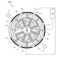
- FIG. 9 is a front view of a structure that plays a central role in another ring-shaped vibrating gyroscope 110 in the present embodiment.
- this ring-shaped vibrating gyroscope 110 is a modification in which the suppressing electrode is not provided in the 9 o'clock direction, and the suppressing electrode 13d is provided in the 3 o'clock direction only. is there.
- the feedback control circuit 61 is not used, and the output from the detection electrode 13b provided in the 6 o'clock direction is input to the feedback control circuit 62 together with the output from the detection electrode 13b provided in the 12 o'clock direction.
- the feedback control circuit 62 is also used to generate a voltage to be applied to the suppression electrode 13d provided in the 3 o'clock direction.
- the ring-shaped vibrating gyroscope 110 has the same configuration as the ring-shaped vibrating gyroscope 100 of the first embodiment except for the above-described change point.
- the manufacturing method is the same as that of the first embodiment except for a part.
- the vibration mode of the present embodiment is a vibration mode of cos 2 ⁇ , as in the first embodiment. Therefore, the description overlapping with the first embodiment may be omitted.
- the secondary vibration can be suppressed by the suppression electrode 13 d.
- the ring-shaped vibrating gyroscope 110 is also similar to the ring-shaped vibrating gyroscope 100 in that the vibration in the rocking mode substantially does not adversely affect the operation when a disturbance accompanied by a vibration that excites the rocking mode occurs. is there. This is because, as shown in FIG. 9, since the detection electrodes 13b and 13b are disposed at positions separated by 180.degree. In the circumferential direction, respectively, expansion and contraction of the piezoelectric film 40 on the leg portions connected to the detection electrodes 13b and 13b. Is the opposite.
- the ring-shaped vibrating gyroscope 110 has an advantage that the electrical wiring and the feedback control circuit are simplified as compared with the ring-shaped vibrating gyroscope 100 in which the suppression electrodes 13 b and 13 b are provided in the 3 o'clock and 9 o'clock directions.
- the ring-shaped vibrating gyroscope 100 is superior to the ring-shaped vibrating gyroscope 110 in the effect of suppressing the secondary vibration, and can realize a responsive gyro with good response.
- directions of 3 o'clock and 9 o'clock in the suppression electrodes 13d and 13d for suppressing secondary vibration as compared with the ring-shaped vibrating gyroscope 110. It is because it is provided in.
- the driving force for suppressing the secondary vibration acts on the ring-shaped vibrating body 11 with good symmetry.
- the suppression electrodes 13d and 13d are arranged so as to be 180 degrees apart from each other as compared to the ring-shaped vibrating gyroscope 110. This is because the primary vibration is in the cos 2 ⁇ mode. In the case where the primary vibration is in the cos N ⁇ mode (N is a natural number of 2 or more), the plurality of suppression electrodes 13 d,... 13 d are at an angle apart from each other by (360 / N) °. Can be placed.
- FIG. 10 is a front view of a structure that plays a central role in another ring-shaped vibrating gyroscope 120 in the present embodiment.
- this ring-shaped vibrating gyroscope 120 is a modification in which the detecting electrode 13b is provided only in the 12 o'clock direction without providing the detecting electrode in the 6 o'clock direction. is there.
- the output from the detection electrode 13 b provided in the 12 o'clock direction is input to the feedback control circuit 62 without using the feedback control circuit 61.
- the feedback control circuit 62 is used to generate a voltage to be applied to the suppression electrode 13d provided in the 3 o'clock and 9 o'clock directions.
- the ring-shaped vibrating gyroscope 120 has the same configuration as the ring-shaped vibrating gyroscope 100 of the first embodiment except for the above-mentioned change point.
- the manufacturing method is the same as that of the first embodiment except for a part.
- the vibration mode of the present embodiment is a vibration mode of cos 2 ⁇ , as in the first embodiment. Therefore, the description overlapping with the first embodiment may be omitted.
- the ability to suppress secondary vibration is almost equal secured to There is an advantage that the feedback control circuit can be simplified.
- the vibration in the rocking mode does not substantially adversely affect the operation of the ring-shaped vibrating gyroscope 100 as compared with the ring-shaped vibrating gyroscope 120.
- Excellent. This is because the detection electrodes 13b and 13b for detecting the secondary vibration are provided in the 12 o'clock and 6 o'clock directions, so that when the disturbance accompanied by the vibration that excites the rocking mode occurs, the detection electrode 13b , 13b are reversed in expansion and contraction of the piezoelectric film 40 on the leg portion.
- the detection electrodes 13b and 13b are arranged so as to be 180 degrees apart from each other as compared to the ring-shaped vibrating gyroscope 120, but this is because the primary vibration is in the cos 2 ⁇ mode.
- the plurality of detection electrodes 13b,... 13b have angles separated by (360 / N) ° from each other. Can be placed.
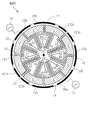
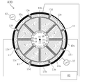
- FIG. 11 is a front view of a structure that plays a central role in another ring-shaped vibrating gyroscope 400 in the present embodiment.
- the ring-shaped vibrating gyroscope 400 of this embodiment has the same configuration as the ring-shaped vibrating gyroscope 100 of the first embodiment except for the arrangement of the upper metal film 50 in the first region related to the monitor electrode in the first embodiment. Equipped with Moreover, the manufacturing method is the same as that of the first embodiment except for the pattern formed by the photolithography technique.
- the vibration mode of the present embodiment is a vibration mode of cos 2 ⁇ , as in the first embodiment. Therefore, the description overlapping with the first embodiment may be omitted. Also in FIG. 11, the feedback control circuits 61 and 62 are omitted for the sake of convenience in order to make the drawing easy to see.
- the ring-shaped vibrating gyroscope 400 of the present embodiment includes four monitor electrodes 413c,..., 413c as shown in FIG. 11, and the respective monitor electrodes 413c,.
- the electrode pads 18,..., 18 are connected.
- These monitor electrodes 413c,..., 413c detect the amplitude and resonance frequency of the primary vibration of the ring-shaped vibrating body 11 as in the first embodiment, and transmit a signal to a known feedback control circuit not shown. Do. As a result, the ring-shaped vibrating body 11 maintains a constant vibration.
- the monitor electrodes 413c,..., 413c do not necessarily have to be disposed at an angle of (180/2) °, that is, 90 ° from the respective drive electrodes 13a, 13a. Even with the arrangement of the monitor electrodes 413c,..., 413c shown in FIG. That is, by adopting the structure of the present embodiment, the drive force, detection ability, and suppression force of the vibration gyro utilizing in-plane vibration are exhibited, and the S / N ratio is not sacrificed without sacrificing responsiveness. A dramatically enhanced vibration gyro can be obtained.
- the monitor electrodes 413c,..., 413c are separated by equal angles (less than 22.5 °) from the drive electrodes 13a, 13a, respectively. It is arranged. For this reason, the influence of the nonuniformity of the detection sensitivity caused by the positional deviation of the monitor electrodes 413c,..., 413c caused by the variation in the manufacturing process is reduced. In addition, it is possible to keep the magnitude of the primary vibration constant without being affected by the newly generated secondary vibration because the outputs of opposite phases due to the secondary vibration of the ring-shaped vibrating body 11 mutually suppress each other. It becomes possible.
- FIG. 12 is a front view of a structure that plays a central role in another ring-shaped vibrating gyroscope 500 in the present embodiment.
- the ring-shaped vibrating gyroscope 500 of the present embodiment has the same configuration as the ring-shaped vibrating gyroscope 100 of the first embodiment except for the arrangement of the upper metal film 50 in the first region in the first embodiment.
- the manufacturing method is the same as that of the first embodiment except for the pattern formed by the photolithography technique.
- the vibration mode of the present embodiment is a vibration mode of cos 2 ⁇ , as in the first embodiment. Therefore, the description overlapping with the first embodiment may be omitted.
- the feedback control circuits 61 and 62 are omitted for the sake of convenience in order to make the drawing easy to see.
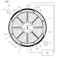
- the ring-shaped vibrating gyroscope 500 of the present embodiment includes two monitor electrodes 513c, 513c as shown in FIG. 12, and the respective monitor electrodes 513c, 513c are connected to the electrode pads 18, 18 via the lead-out electrodes. ing. As in the first embodiment, these monitor electrodes 513 c and 513 c detect the amplitude and resonance frequency of the primary vibration of the ring-shaped vibrating body 11 and transmit a signal to a known feedback control circuit (not shown). As a result, the ring-shaped vibrating body 11 maintains a constant vibration.
- the monitor electrodes 513c, 513c do not necessarily have to be disposed at an angle of (180/2) °, that is, 90 ° from the respective drive electrodes 13a, 13a. Even with the arrangement of the monitor electrodes 513c, 513c shown in FIG. 12, the main effect of the present invention is exhibited. That is, by adopting the structure of the present embodiment, the drive force, detection ability, and suppression force of the vibration gyro utilizing in-plane vibration are exhibited, and the S / N ratio is not sacrificed without sacrificing responsiveness. A dramatically enhanced vibration gyro can be obtained.
- the monitor electrodes 513c, 513c are separated by equal angles (less than 22.5 °) clockwise in the clockwise direction, with an angle of 90 ° apart from the drive electrodes 13a, 13a. It is arranged. For this reason, it is possible to reduce the influence of the nonuniformity of the detection sensitivity caused by the positional deviation of the monitor electrodes 513c, 513c caused by the variation in the manufacturing process. Even when the monitor electrodes 513c, 513c are disposed at an equal angle in the counterclockwise direction with respect to the angle separated by 90 ° from the drive electrodes 13a, 13a, the same effect as described above is achieved. Be done.
- FIG. 13 is a front view of a structure that plays a central role in another ring-shaped vibrating gyroscope 600 in the present embodiment.
- the ring-shaped vibrating gyroscope 600 of this embodiment has the same configuration as the ring-shaped vibrating gyroscope 100 of the first embodiment except for the arrangement of the upper metal film 50 in the first region in the first embodiment.
- the manufacturing method is the same as that of the first embodiment except for the pattern formed by the photolithography technique.
- the vibration mode of the present embodiment is a vibration mode of cos 2 ⁇ , as in the first embodiment. Therefore, the description overlapping with the first embodiment may be omitted.
- the feedback control circuits 61 and 62 are omitted for the sake of convenience in order to make the drawing easy to see.
- the ring-shaped vibrating gyroscope 600 includes two monitor electrodes 613c, 613c as shown in FIG. 13, and the respective monitor electrodes 613c, 613c are connected to the electrode pads 18, 18 through the lead electrodes. ing. As in the first embodiment, these monitor electrodes 613 c and 613 c detect the amplitude and resonance frequency of the primary vibration of the ring-shaped vibrating body 11 and transmit a signal to a known feedback control circuit (not shown). As a result, the ring-shaped vibrating body 11 maintains a constant vibration.
- the monitor electrodes 613c and 613c do not necessarily have to be disposed at an angle of (180/2) °, that is, 90 ° from the respective drive electrodes 13a and 13a. Even with the arrangement of the monitor electrodes 613c and 613c shown in FIG. 13, the main effect of the present invention is exhibited. That is, by adopting the structure of the present embodiment, the drive force, detection ability, and suppression force of the vibration gyro utilizing in-plane vibration are exhibited, and the S / N ratio is not sacrificed without sacrificing responsiveness. A dramatically enhanced vibration gyro can be obtained.
- one of the monitor electrodes 613c and 613c is counterclockwise, and the other is an equal angle (22.5 °), with an angle of 90 ° away from each of the drive electrodes 13a and 13a.
- the outputs of the opposite phases due to it are mutually suppressed, so that the primary vibration is not affected by the newly generated secondary vibration. It becomes possible to keep the size constant.
- FIG. 14A is a front view of a structure that plays a central role in another ring-shaped vibrating gyroscope 700 in the present embodiment.
- the ring-shaped vibrating gyroscope 700 of the present embodiment has the same configuration as the ring-shaped vibrating gyroscope 100 of the first embodiment except for the arrangement of the upper metal film 50 in the first region in the first embodiment.
- the manufacturing method is the same as that of the first embodiment except for the pattern formed by the photolithography technique.
- the vibration mode of the present embodiment is a vibration mode of cos 2 ⁇ , as in the first embodiment. Therefore, the description overlapping with the first embodiment may be omitted.
- the feedback control circuits 61 and 62 are omitted for the sake of convenience in order to make the drawing easy to see.
- the ring-shaped vibrating gyroscope 700 includes two monitor electrodes 513c and 513c, and the respective monitor electrodes 713c and 713c are connected to the electrode pads 18 and 18 through the lead electrodes. ing. As in the first embodiment, these monitor electrodes 713c and 713c detect the amplitude and resonance frequency of the primary vibration of the ring-shaped vibrating body 11, and transmit a signal to a known feedback control circuit (not shown). As a result, the ring-shaped vibrating body 11 maintains a constant vibration.
- the monitor electrodes 713c and 713c do not necessarily have to be disposed at an angle of (180/2) °, that is, 90 ° from the respective drive electrodes 13a and 13a. Even with the arrangement of the monitor electrodes 713c and 713c shown in FIG. 14A, the main effect of the present invention is exhibited. That is, by adopting the structure of the present embodiment, the driving force, detection ability, and suppression force of the vibration gyro utilizing in-plane vibration are exhibited, and the S / N ratio is not sacrificed. Can dramatically improve the vibration gyro.
- the monitor electrodes 713c and 713c are separated by equal angles (less than 22.5 °) in the counterclockwise direction centering on the angles separated by 90 ° from the drive electrodes 13a and 13a. Is located in For this reason, the influence of the nonuniformity of the detection sensitivity caused by the positional deviation of the monitor electrodes 413c,..., 413c caused by the variation in the manufacturing process is reduced. Even when the monitor electrodes 713c and 713c are disposed at equal angles in the clockwise direction with respect to the angles 90 ° apart from the drive electrodes 13a and 13a, the same effect as described above is obtained. Ru.
- FIG. 14B is a front view of a structure that plays a central role in another ring-shaped vibrating gyroscope 750 in the present embodiment.
- the ring-shaped vibrating gyroscope 750 of this embodiment has the same configuration as the ring-shaped vibrating gyroscope 100 of the first embodiment except for the arrangement of the upper metal film 50 in the first region in the first embodiment.
- the manufacturing method is the same as that of the first embodiment except for the pattern formed by the photolithography technique.
- the vibration mode of the present embodiment is a vibration mode of cos 2 ⁇ , as in the first embodiment. Therefore, the description overlapping with the first embodiment may be omitted.
- the feedback control circuits 61 and 62 are omitted for the sake of convenience in order to make the drawing easy to see.
- the ring-shaped vibrating gyroscope 750 includes two monitor electrodes 753 c and 753 c as shown in FIG. 14B, and the respective monitor electrodes 753 c and 753 c are connected to the electrode pads 18 and 18 via extraction electrodes. ing. As in the first embodiment, these monitor electrodes 753 c and 753 c detect the amplitude and resonance frequency of the primary vibration of the ring-shaped vibrating body 11 and transmit a signal to a known feedback control circuit (not shown). As a result, the ring-shaped vibrating body 11 maintains a constant vibration.
- the monitor electrodes 753c and 753c do not necessarily have to be disposed at an angle of (180/2) °, that is, 90 ° from the respective drive electrodes 13a and 13a. Even with the arrangement of the monitor electrodes 753 c and 753 c shown in FIG. 14B, the main effect of the present invention is exhibited.
- one of the monitor electrodes 753 c and 753 c on the outer peripheral side of the ring-shaped vibrating body 11 has a ring shape in the counterclockwise direction, with an angle of 90 ° apart from each drive electrode 13 a and 13 a
- the other one on the inner peripheral side of the vibrating body 11 is disposed at an angle separated by equal angles (less than 22.5 °) clockwise.
- the monitor electrodes are not necessarily angled apart from each of the drive electrodes 13a and 13a by (180/2) degrees, that is, 90 degrees. It does not have to be placed in Specifically, in the case of the vibration mode of cos N ⁇ , each monitor electrode is more than ⁇ (180 / N) ⁇ (45 / N) ⁇ ° from each drive electrode ⁇ (180 / N) + (45 / N) ⁇ ° An area of an angle less than the distance apart, and each monitor electrode of the area from the outer peripheral edge of the ring-shaped vibrating body 11 to the vicinity of the outer peripheral edge and / or its inner peripheral edge to its inner peripheral edge.
- the main effect of the present invention is exhibited by being arranged in the region up to the vicinity.
- the arrangement of the monitor electrode in the above-described range most places the arrangement of other electrode groups and / or the arrangement of the lead-
- FIG. 15 is a front view of a structure that plays a central role in another ring-shaped vibrating gyroscope 800 in the present embodiment.
- the ring-shaped vibrating gyroscope 800 of this embodiment is the same as the ring of the first embodiment except for the arrangement of the leg portions 15,..., 15 in the first embodiment and the arrangement of the upper metal film 50 in the first region. It has the same configuration as that of the vibrating vibratory gyroscope 100.
- the manufacturing method is the same as that of the first embodiment except for the pattern formed by the photolithography technique.
- the vibration mode of the present embodiment is a vibration mode of cos 2 ⁇ , as in the first embodiment. Therefore, the description overlapping with the first embodiment may be omitted.
- the feedback control circuits 61 and 62 are omitted for the sake of convenience in order to make the drawing easy to see.
- the ring-shaped vibrating gyroscope 800 includes the drive electrodes 13a,..., 13a (a part of the AC power supply 12 is omitted), the detection electrodes 13b,.
- the region from the outer peripheral edge of the ring-like vibrating body 11 to the vicinity of the outer peripheral edge of the ring-shaped vibrating body 11 and the vicinity of the inner peripheral edge thereof Are arranged in the area up to.
- each of the monitor electrodes 13c, 13c is disposed in a region from the outer peripheral edge of the ring-shaped vibrating body 11 to the vicinity of the outer peripheral edge.
- the primary vibration of the ring-shaped vibrating gyroscope 800 is excited in the vibration mode of cos 2 ⁇ . Therefore, the breakdown of the plurality of electrodes 13a to 13d is as follows (a) to (d). (A) In the region from the outer peripheral edge of the ring-shaped vibrating body 11 to the vicinity of the outer peripheral edge, two drive electrodes 13a and 13a arranged at an angle of 180 ° in the circumferential direction, and ring-shaped vibration In the region from the inner peripheral edge of the body 11 to the vicinity of the inner peripheral edge, two drive electrodes 13a and 13a arranged at an angle of 180 ° apart in the circumferential direction.
- the detection electrodes 13b,..., 13b are at an angle 45 ° clockwise from the drive electrodes 13a,.
- the suppression electrodes 13 d,..., 13 d are disposed at an angle of 90 ° in the circumferential direction from the detection electrodes 13 b,.
- the detection electrodes 13b, ..., 13b and the suppression electrodes 13d, ..., 13d are rings that are inclined 45 ° with respect to the vibration axis of the primary vibration generated by the drive electrodes 13a, ..., 13a. It is disposed on the oscillation axis of the secondary vibration generated when an angular velocity is given to the vibrating body 11.
- the phase of the drive voltage for the drive electrodes 13a,..., 13a in the region from the outer peripheral edge of the ring-shaped vibrating body 11 to the vicinity of the outer peripheral edge is the inner peripheral edge to the inner peripheral edge
- the phases detected by the detection electrodes 13b,..., 13b arranged in the region from the outer peripheral edge of the ring-shaped vibrating body 11 to the vicinity of the outer peripheral edge are from the inner peripheral edge to the vicinity of the inner peripheral edge
- various electrodes are disposed in the region from the outer peripheral edge of the ring-shaped vibrating body 11 to the vicinity of the outer peripheral edge, and from the inner peripheral edge to the vicinity of the inner peripheral edge Even in the case of being arranged in the area, the same effects as the effects of the above-described embodiments can be obtained. That is, by adopting the structure of the present embodiment, the driving force, detection ability, and suppression force of the vibration gyro utilizing in-plane vibration are exhibited, and the S / N ratio is not sacrificed. Can dramatically improve the vibration gyro.
- the ring-shaped vibrating gyroscope 800 of this embodiment is also a preferable embodiment because the driving ability of the ring-shaped vibrating body 11 and the detection ability of the secondary vibration are improved.
- the detection electrodes 13b, ..., 13b and the suppression electrodes 13d, ..., 13d are inclined 45 ° clockwise and counterclockwise with respect to the vibration axis of the above-mentioned primary vibration.
- the present invention is not limited thereto.
- at least a part of the present embodiment may be disposed on the oscillation axis of only one of the clockwise or counterclockwise secondary oscillations inclined 45 ° with respect to the oscillation axis of the above-described primary oscillation.
- either the clockwise or counterclockwise direction of the present embodiment is 45 ° inclined with respect to the vibration axis of the above-mentioned primary vibration. It is more preferable than the case where it is disposed on the vibration axis of only one secondary vibration.
- FIG. 16 is a front view of a structure that plays a central role in another ring-shaped vibrating gyroscope 820 in the present embodiment.
- the ring-shaped vibrating gyroscope 820 of the present embodiment is the ring-shaped vibrating gyroscope 800 of the tenth embodiment except that the ring-shaped vibrating gyroscope 820 includes the arrangement and functions of some electrodes and the arithmetic circuit 63 connected to several electrodes.
- the manufacturing method is the same as that of the first embodiment except for the pattern formed by the photolithography technique.
- the vibration mode of the present embodiment is a vibration mode of cos 2 ⁇ , as in the first embodiment. Therefore, the description overlapping with the first embodiment may be omitted.
- the feedback control circuits 61 and 62 are omitted for the sake of convenience in order to make the drawing easy to see.
- the ring-shaped vibrating gyroscope 820 includes, as shown in FIG. 16, the drive electrodes 13a,..., 13a (a part of the AC power supply 12 is omitted) and the first detection electrodes 13b. , 13b are arranged in the region from the outer peripheral edge of the ring-shaped vibrating body 11 to the vicinity of the outer peripheral edge. Further, each of the monitor electrodes 13c, 13c is disposed in a region from the outer peripheral edge of the ring-shaped vibrating body 11 to the vicinity of the outer peripheral edge. Further, the respective suppression electrodes 13 d and 13 d are disposed in the region from the inner peripheral edge of the ring-shaped vibrating body 11 to the vicinity of the inner peripheral edge.
- each of the second detection electrodes 13 e and 13 e is disposed in a region from the outer peripheral edge of the ring-shaped vibrating body 11 to the vicinity of the outer peripheral edge. That is, the difference from the tenth embodiment is that two of the first detection electrodes of the tenth embodiment are removed and two of the suppression electrodes 13d,..., 13d are ring-shaped. This is a point replaced with the second detection electrodes 13 e and 13 e that detect secondary vibration generated when an angular velocity is given to the vibrating gyroscope 820.
- the first detection electrode 13b of this embodiment corresponds to the detection electrode 13b of the tenth embodiment.
- the present embodiment after primary vibration is excited by the drive electrodes 13a,..., 13a, the angular velocity is around the vertical axis (direction perpendicular to the paper surface) on which the ring-shaped vibrating gyroscope 820 shown in FIG.
- Coriolis force causes a secondary vibration having a new vibration axis inclined 45 ° on both sides with respect to the vibration axis of the primary vibration.
- the secondary vibration is detected by the two first detection electrodes 13 b and 13 b and the two second detection electrodes 13 e and 13 e.
- the present embodiment also includes a feedback control circuit (not shown).
- the first detection electrodes 13 b and 13 b and the second detection electrodes 13 e and 13 e are respectively disposed corresponding to the vibration axis of the secondary vibration.
- the first detection electrodes 13 b and 13 b and the second detection electrodes 13 e and 13 e are formed outside the center line of the upper surface of the ring-shaped vibrating body 11.
- the piezoelectric films 40 at the positions of the two detection electrodes 13e extend in the direction of the arrow shown in B2, so that their electrical signals are reversed also in this case. Note that the above-described contents described with reference to FIG. 17 also apply to a ring-shaped vibrating gyroscope of a vibration mode of cos 2 ⁇ other than this embodiment.
- the arithmetic circuit 63 which is a known difference circuit, electric signals of the first detection electrodes 13b and 13b and the second detection electrodes 13e and 13e formed outside the center line of the upper surface of the ring-shaped vibrating body 11 Difference is calculated. As a result, the detection signal of the secondary vibration has a detection capability higher than that of the first detection electrodes 13b and 13b alone.
- the upper metal film 50, the piezoelectric film 40, and the lower metal film 30 as the lead-out electrode 14 are formed on the leg portions 15,.
- the leg portions 15 to 15 are vertical axes of the ring-shaped vibrating gyroscope 820.
- the piezoelectric film 40 on the leg portions 15,..., 15 are generated.
- the first detection electrodes 13 b and 13 b formed outside the center line on the top surface of the ring-shaped vibrating body 11 Since they are respectively disposed at 180 ° apart in the circumferential direction, the expansion and contraction of the piezoelectric films 40 on the leg portions connected to the first detection electrodes 13b and 13b are reversed. As a result, since the positive and negative of the electric signal of those 1st detection electrodes 13b become reverse, those electric signals will mutually offset each other. The above-mentioned phenomenon applies to the above-mentioned electric signal of the leg connected to each second detection electrode 13d. Therefore, the vibration of the rocking mode does not substantially affect the ring-shaped vibrating gyroscope 820.
- the ring-shaped vibrating gyroscope 820 includes the four first detection electrodes 13 b and 13 b and the two second detection electrodes 13 e and 13 e, thereby enhancing the detection capability of the secondary vibration. Impact resistance to external impacts that excite vibrations in the bounce mode and the locking mode is also enhanced.
- the present invention is not limited to this.
- the drive electrode 13a is disposed in only one of the region from the outer peripheral edge of the ring-shaped vibrating body 11 to the vicinity of the outer peripheral edge or the region from the inner peripheral edge to the vicinity of the inner peripheral edge. It is good.
- the present embodiment is preferable.
- two each 1st detection electrode 13b, 13b was arrange
- four first detection electrodes 13b,..., 13b may be arranged.
- FIG. 19 is a front view of a structure that plays a central role in another ring-shaped vibrating gyroscope 840 in the present embodiment.
- the ring-shaped vibrating gyroscope 840 of the present embodiment has the same configuration as the ring-shaped vibrating gyroscope 800 of the tenth embodiment except for the arrangement and functions of some electrodes.
- the manufacturing method is the same as that of the first embodiment except for the pattern formed by the photolithography technique.
- the vibration mode of the present embodiment is a vibration mode of cos 2 ⁇ , as in the first embodiment. Therefore, the description overlapping with the first embodiment may be omitted.
- the feedback control circuits 61 and 62 are omitted for the sake of convenience in order to make the drawing easy to see.
- the ring-shaped vibrating gyroscope 840 includes the drive electrodes 13a,..., 13a (a part of the AC power supply 12 is omitted), the respective first detection electrodes 13b. , 13b are arranged in the region from the outer peripheral edge of the ring-shaped vibrator 11 to the vicinity of the outer peripheral edge and in the region from the inner peripheral edge to the vicinity of the inner peripheral edge. Further, each of the monitor electrodes 13c, 13c is disposed in a region from the outer peripheral edge of the ring-shaped vibrating body 11 to the vicinity of the outer peripheral edge.
- the respective suppression electrodes 13 d and 13 d are disposed in the region from the outer peripheral edge of the ring-shaped vibrating body 11 to the vicinity of the outer peripheral edge.
- each of the second detection electrodes 13 e and 13 e is disposed in a region from the inner peripheral edge of the ring-shaped vibrating body 11 to the vicinity of the inner peripheral edge. That is, the difference from the modification (1) of the tenth embodiment is that the second detection electrode 13e of the modification (1) of the tenth embodiment is replaced with the suppression electrode 13d of the same embodiment. .
- the first detection electrode 13b of this embodiment corresponds to the detection electrode 13b of the tenth embodiment.
- the angular velocity is around the vertical axis (direction perpendicular to the paper surface) on which the ring-shaped vibrating gyroscope 840 shown in FIG.
- Coriolis force causes a secondary vibration having a new vibration axis inclined 45 ° on both sides with respect to the vibration axis of the primary vibration.
- the secondary vibration is detected by the two first detection electrodes 13 b and 13 b and the two second detection electrodes 13 e and 13 e.
- the present embodiment also includes a feedback control circuit (not shown), and the feedback control circuit suppresses secondary vibration in response to signals from the first and second detection electrodes 13 b and 13 e. Signal is output to the suppression electrodes 13d and 13d.
- the first detection electrodes 13 b and 13 b and the second detection electrodes 13 e and 13 e are respectively disposed corresponding to the vibration axis of the secondary vibration.
- the first detection electrodes 13 b and 13 b are formed outside the center line of the top surface of the ring-shaped vibrating body 11, and the second detection electrodes 13 e and 13 e are more than the center line of the top surface of the ring-shaped vibrating body 11. It is formed inside.
- the arithmetic circuit 63 which is a known difference circuit, the first detection electrodes 13b and 13b formed outside the center line of the upper surface of the ring-shaped vibrating body 11 and the inside of the center line thereof By calculating the difference between the electric signals of the second detection electrodes 13e and 13e, the detection signal of the secondary vibration has a detection capability higher than that of the first detection electrodes 13b and 13b alone.
- the ring-shaped vibrating gyroscope 840 of the present embodiment enhances the detection capability of the secondary vibration and excites the vibration in the bounce mode and the locking mode. Impact resistance to external impact is also enhanced.
- the present invention is limited thereto It is not a thing.
- the first and second detection electrodes 13b and 13e are used, and two suppression electrodes 13d and 13d are used.
- the first detection electrode 13b or the second detection electrode 13e is used. A configuration in which only one of them is used or a configuration in which only one suppression electrode 13 d is used are also included in the scope of the present invention.
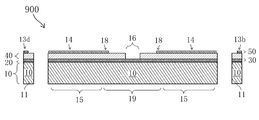
- FIG. 20A is a front view of a structure that plays a central role in another ring-shaped vibrating gyroscope 900 in the present embodiment.
- FIG. 20B is a cross-sectional view taken along a line TT in FIG. 20A.
- the ring-shaped vibrating gyroscope 900 of the present embodiment is the first embodiment except for the arrangement of the upper metal film 50 in the first region and the fixed ends 17 for the electrode pads in the first embodiment.
- the ring-shaped vibrating gyroscope 100 has substantially the same configuration.
- the manufacturing method is the same as that of the first embodiment except for various patterns formed by the photolithography technique.
- the vibration mode of the present embodiment is a vibration mode of cos 3 ⁇ unlike the first embodiment. Therefore, the description overlapping with the first embodiment may be omitted.
- the feedback control circuits 61 and 62 are omitted for the sake of convenience in order to make the drawing easy to see.
- an X axis and a Y axis are shown in FIG. 20A.
- the diagonal lines and the letter V described in the drawings of the other embodiments are omitted.
- each upper metal film 50 of the ring-shaped vibrating gyroscope 900 of the present embodiment is formed outside the center line.
- the vibration mode of the primary vibration of this embodiment is a vibration mode of cos 3 ⁇ of the in-plane shown in FIG. 21A.
- the vibration mode of the secondary vibration in the present embodiment is an in-plane vibration mode of cos 3 ⁇ shown in FIG. 21B. Therefore, the breakdown of the plurality of electrodes 13a to 13e is as the following (a) to (d).
- B When one of the three drive electrodes 13a and 13a described above (for example, the drive electrode 13a in the 12 o'clock direction of the watch in FIG.
- the lead-out electrodes 14 and 14 are formed from both ends of each of the various electrodes in order to eliminate the bias of the electric signal. Even when the lead-out electrode 14 is formed from only one side of various electrodes, the function as the vibrating gyroscope is not lost.
- a region corresponding to the third region of the present embodiment is a support 19 formed of the silicon substrate 10 connected to the above-described leg portions 15 to 15.
- the support 19 also functions as the electrode pad fixed end 17 in the first embodiment.
- a film 40 is formed on the upper surface of the support 19, except for the fixed potential electrode 16 which is a ground electrode, the above-described silicon oxide film 20, lower metal film 30, and piezoelectric body continuous with those on the legs 15,.
- a film 40 is formed.
- the lower metal film 30 formed on the silicon oxide film 20 is at the same potential as the fixed potential electrode 16.
- the above-described lead electrodes 14,..., 14 and the electrode pad 18, which are continuous with those on the leg portions 15,. ..., 18 are formed on the upper surface of the piezoelectric film 40 formed above the support column 19, the above-described lead electrodes 14,..., 14 and the electrode pad 18, which are continuous with those on the leg portions 15,.
- each electrode provided in the ring-shaped vibrating gyroscope 900 will be described.
- the primary vibration of the in-plane cos 3 ⁇ vibration mode is excited. Since the fixed potential electrode 16 is grounded, the lower layer electrode film 30 formed continuously with the fixed potential electrode 16 is uniformly at 0V.
- an alternating voltage of 1VP-0 is applied to the three drive electrodes 13a, 13a, 13a.
- the piezoelectric film 40 expands and contracts to excite primary vibration.
- the upper metal film 50 is formed outside the center line of the upper surface of the ring-shaped vibrating member 11, the upper metal film 50 is not formed on the side surface of the ring-shaped vibrating member 11. It becomes possible to convert the stretching movement into the primary vibration of the ring-shaped vibrating body 11.
- the actual alternating current power supply 12 is applied to the drive electrode 13a via the electrode pad 18 connected to the conductive wire, this embodiment and other embodiments may be omitted for convenience of explanation.
- monitor electrodes 13c, 13c and 13c shown in FIG. 20A detect the amplitude and resonant frequency of the above-mentioned primary vibration, and transmit a signal to a known feedback control circuit (not shown).
- the feedback control circuit of this embodiment controls so that the frequency of the AC voltage applied to the drive electrodes 13a, 13a, 13a matches the natural frequency of the ring-shaped vibrating body 11, and the amplitude of the ring-shaped vibrating body 11. Is controlled using the signals of the monitor electrodes 13c, 13c, 13c so as to have a certain value. As a result, the ring-shaped vibrating body 11 maintains a constant vibration.
- the vibration mode is cos3 ⁇ in plane.
- the Coriolis force causes the secondary vibration shown in FIG. 20B having a new vibration axis inclined 30 ° on both sides with respect to the vibration axis of the primary vibration shown in FIG. 20A.
- This secondary vibration is detected by the three detection electrodes 13b, 13b and 13b.
- the ring-shaped vibrating gyroscope 900 of the present embodiment makes the value of the voltage signal zero in other words.
- a feedback control circuit (not shown) is provided which instructs or controls to apply a specific voltage to the suppression electrodes 13d, 13d, 13d. Note that this particular voltage is used as a result output as a vibrating gyroscope.
- the ring-shaped vibrating gyroscope 900 includes the ring-shaped vibrating body 11 by including the suppression electrodes 13d, 13d and 13d for suppressing the secondary vibration based on the voltage signals from the detection electrodes 13b, 13b and 13b.
- the performance as a vibrating gyroscope can be exhibited with almost no secondary vibration.
- the ring-shaped vibrating gyroscope 900 according to the present embodiment is extremely excellent in noise performance as compared with a vibrating gyroscope in which the suppression electrodes 13d, 13d, 13d and the feedback control circuit are not provided.
- the ring-shaped vibrating gyroscope 900 according to the present embodiment is compared with an example (a vibrating gyroscope according to the eleventh embodiment) described in PCT / JP2008 / 071372 previously proposed by the present applicant.
- the magnitude of noise in the low frequency region is less than half. Therefore, the S / N ratio can be dramatically improved without sacrificing responsiveness.
- the ring-shaped vibrating gyroscope 900 includes the detection electrodes 13b, 13b, 13b and the suppression electrodes 13d, 13d, 13d to detect the secondary vibration even in the vibration mode of cos 3 ⁇ . And the impact resistance to external impact that excites the rocking mode vibration is also enhanced.
- the electrodes are formed by patterning the upper metal film 50 without etching the piezoelectric film 40.
- the present invention is not limited to this.
- the piezoelectric film 40 is etched according to the area where the upper metal film 50 is substantially formed, as in the second embodiment. Undesired expansion and contraction of the piezoelectric film 40 and oscillation of the electrical signal are prevented.
- a silicon oxide film is employed as the insulating film on the silicon substrate, but the present invention is not limited to this.
- a silicon nitride film or a silicon oxynitride film is formed instead of the silicon oxide film, substantially the same effect as the effect of the present invention is exerted.
- the vibration mode of cos 2 ⁇ is adopted, but the present invention is not limited to this.
- N is a natural number of 2 or more
- substantially the same effect as that of the present invention can be achieved by adopting a drive electrode that excites the primary vibration of the ring-shaped vibrating body in the vibration mode of cos N ⁇ .
- the arrangement of the electrodes of the eleventh embodiment in which the vibration mode of cos 3 ⁇ is adopted is equivalent to cos 3 ⁇ corresponding to each of the first to tenth embodiments and the modification of the tenth embodiment described above to those skilled in the art.
- the arrangement of the electrodes in the vibration mode is fully disclosed. That is, the arrangement of the electrodes of the vibration mode of cos N ⁇ when N is a natural number of 2 or more is sufficiently disclosed by the description of each of the embodiments described above.
- each embodiment is demonstrated by the vibration gyro which used the annular
- a regular polygonal oscillator such as a regular hexagon, a regular octagon, a regular dodecagon, and a regular icosagon
- substantially the same effects as the effects of the present invention can be obtained.
- it may be a vibrating body such as an octagonal vibrating body 111 of the ring-shaped vibrating gyroscope 950 shown in FIG.
- n is an arbitrary natural number
- the “annular ring” includes an elliptical shape.
- the ring-shaped vibrating gyroscope which uses silicon as a base material is adopted in each above-mentioned embodiment, it is not limited to this.
- the base material of the vibrating gyroscope may be germanium or silicon germanium.
- adoption of silicon or silicon germanium can greatly contribute to improvement of the processing accuracy of the entire gyro including the vibrator, since a known anisotropic dry etching technique can be applied.
- each electrode is formed by patterning the upper metal film, but the present invention is not limited to this.
- the present invention is not limited to this.
- the present invention is not limited to this.
- only the upper metal film is patterned as in each of the embodiments described above.
- the present invention can be applied to a part of various devices such as a car, an aircraft, a robot and the like as a vibrating gyroscope.
Landscapes
- Physics & Mathematics (AREA)
- Engineering & Computer Science (AREA)
- General Physics & Mathematics (AREA)
- Radar, Positioning & Navigation (AREA)
- Remote Sensing (AREA)
- Gyroscopes (AREA)
Abstract
本発明の1つの振動ジャイロは、リング状振動体11と、リング状振動体11を柔軟に支持するレッグ部15と、上層金属膜及び下層金属膜により圧電体膜を厚み方向に挟む複数の電極13a~13d及び固定電位電極16とを備えている。複数の電極13a~13dは、一次振動を励起する一群の駆動電極13aと、二次振動を検出する検出電極13bと、検出電極13bからの電圧信号に基づいてその二次振動を抑制する抑制電極13dとを含み、駆動電極13a、検出電極13b、及び抑制電極13dは、リング状振動体11の外周縁からその外周縁の近傍に至るまでの領域及び/又は内周縁から内周縁の近傍に至るまでの領域に配置されている。
Description
本発明は、圧電体膜を用いた振動ジャイロ及びその振動ジャイロの製造方法に関する。
近年、圧電材料を用いた振動ジャイロすなわち振動を利用するジャイロスコープ又は角速度センサが盛んに開発されている。従来から、特許文献1に記載されているような振動体自体が圧電材料で構成されるジャイロが開発される。その一方、振動体上に形成される圧電体膜を利用するジャイロも存在する。例えば、特許文献2では、圧電材料であるPZT膜を用いることによって、振動体の一次振動を励起するとともに、その振動体に角速度が与えられた際に、その振動体に発生するコリオリ力によってジャイロの一部に生じる歪みをも検出する技術が開示されている。
他方、ジャイロが搭載される各種機器のサイズが日進月歩で小型化されている中で、ジャイロそれ自体の小型化も重要な課題である。ジャイロの小型化を達成するためには、ジャイロを構成する各部材の加工精度を格段に高めることが必要となる。また、単に小型化をするだけでなく、ジャイロとしての性能、換言すれば、角速度の検出精度を更に高めることが産業界の強い要望といえる。しかしながら、特許文献2に示されているジャイロの構造は、ここ数年来の小型化及び高性能化の要求を満足するものではない。
上述の通り、圧電体膜を用いた振動ジャイロの小型化と高い加工精度とを達成しつつ、ジャイロとしての高性能化の要求を同時に満足することは非常に難しい。一般的には、ジャイロが小型化されると、振動体に角速度が与えられた場合に、ジャイロの検出電極によって検出される信号が微弱になるという問題がある。従って、小型化された振動ジャイロは本来検出すべき信号と外部からの不意の衝撃(外乱)によって発生する信号との差が小さくなるため、ジャイロとしての検出精度を高めることが難しくなる。
ところで、外部からの不意の衝撃の中には、様々な種類の衝撃が存在する。例えば、上述の特許文献2に記載されたリング状の振動体では、リングの中心の固定ポストを軸として、リングの存在する面の上下方向にシーソーのような動きを与える衝撃がある。この衝撃により、ロッキングモードと呼ばれる振動が励起される。他方、前述の固定ポストに支持された振動体のリング状部材の全周が同時に、リングの存在する面の上方又は下方に曲げられる衝撃も存在する。この衝撃により、バウンスモードと呼ばれる振動が励起される。これらのような衝撃が振動ジャイロに生じたとしても、正確な角速度を検出する技術を確立することは極めて困難である。
本発明は、上述の技術課題を解決することにより、圧電体膜を用いた振動ジャイロすなわち振動を利用するジャイロスコープ又は角速度センサの小型化及び高性能化に大きく貢献するものである。発明者らは、まず、上記の技術課題のうち、外乱に対する影響が比較的小さいと考えられるリング状の振動ジャイロを基本構造として採用した。その上で、発明者らは、一次振動の励起とコリオリ力により形成される二次振動の検出を圧電体膜に担わせることによって、上記各技術課題を解決する構造について鋭意研究を行った。その結果、高い加工精度を達成しうるドライプロセスを圧電体膜を用いた振動ジャイロに適用するためには、振動ジャイロにおける各種電極の特有の配置が必要であることを見出した。加えて、発明者らは、振動ジャイロに対して角速度が与えられたときに発生する二次振動による電気信号の処理を工夫することにより、従来に比べて、応答性を犠牲にすることなく、S/N比が飛躍的に高まることを見出した。本発明はこのような視点で創出された。なお、本出願では、「円環状又は多角形状の振動ジャイロ」を、簡略化して「リング状振動ジャイロ」とも呼ぶ。
本発明の1つの振動ジャイロは、一様な平面を備えたリング状振動体と、そのリング状振動体を柔軟に支持するレッグ部と、そのリング状振動体の平面上又は上方に置かれ、圧電体膜を厚み方向に挟む上層金属膜及び下層金属膜の少なくともいずれにより形成される複数の電極とを備えている。ここで、前述の複数の電極は、Nを2以上の自然数とした場合に、cosNθの振動モードでそのリング状振動体の一次振動を励起する、互いに円周方向に(360/N)°離れた角度に配置された一群の駆動電極と、前述の駆動電極のいずれかから時計回り及び/又は反時計回りに(90/N)°離れた角度に配置され、かつ前述のリング状振動体に角速度が与えられたときに発生する二次振動を検出する検出電極と、前述の駆動電極のいずれかから時計回り又は反時計回りに(90/N)°離れた角度あるいは前述の検出電極から(180/N)°離れた角度に配置され、かつ前述の検出電極からの電圧信号に基づいて前記二次振動を抑制する抑制電極とを含んでいる。さらに、前述の駆動電極、前述の検出電極、及び前述の抑制電極は、前述のリング状振動体の外周縁からその外周縁の近傍に至るまでの領域及び/又は内周縁からその内周縁の近傍に至るまでの領域に配置されている。
この振動ジャイロによれば、リング状振動体が備える平面上であって、上記の特有の領域に圧電素子に対して電圧を印加したり圧電素子のひずみによって生じた電圧信号を拾ったりするための電極が形成されているため、一軸の角速度センサとして一次振動の励起と二次振動の検出が可能となる。つまり、この振動ジャイロでは、リング状振動体の側面に圧電素子を形成せずに、リング状振動体上の圧電素子が配置される平面と同一平面内で一次振動が励起され、かつリング状振動体の動きを制御する構造を有しているため、ドライプロセス技術を用いて高精度に電極及びリング状振動体の加工を行うことが可能となる。また、この振動ジャイロでは、上記の特有な領域に圧電素子を配置することにより、Nを2以上の自然数とした場合のcosNθの振動モードに適用しうる自由度を備えている。すなわち、上記の特有の領域に圧電素子を配置することにより、平面内振動を利用する振動ジャイロの駆動力、検出能力、及び抑制力が発揮される。さらに、この振動ジャイロは、二次振動を検出する検出電極からの電圧信号に基づいてその二次振動を抑制する抑制電極を備えているため、外部からのノイズに対する出力信号の強度の比率、すなわち、S/N比が飛躍的に高まる。なお、cosNθの振動モードの複数の例は、例えば、特表2005-529306号公報、又は、本願出願人による特許出願である特願2007-209014に記載されている。また、本出願において、「柔軟な」とは「振動体が振動可能な程度に」という意味である。また、本出願では、電極の配置を記述するために、基準となる電極から「離れた角度」との表現が用いられる。ここでの角度は、基準となる電極の方位角を0度としたときの各電極の方位角の値である。各電極の方位角は、リング状振動体の円周又は円環の中央部に取った任意の点(例えば、リング状振動体が円形のときは、例えばその円の中心である。以下、この中心を「基準点」という。)からその電極に向かう直線の方位角とすることができる。この直線は、各電極を通過するような任意の直線とすることができ、代表的には、各電極の図形的な中心、重心、又は、いずれかの頂点と上記の基準点とを通過する直線とすることができる。例えば、基準駆動電極から30°離れた角度に配置された電極とは、その電極の中心と、基準駆動電極の中心とが、上記の基準となる電極の方位角に対して30°の角をなすような配置にある電極をいう。なお、特に断りのない限り、角度の表記は時計回りの向きを角度が増加する方向にとって説明するが、角度が増加する方向を反時計回りに定めても、規定された角度の条件を満たす限り、その角度の表記は本発明の範囲内である。
本発明のもう1つの振動ジャイロは、一様な平面を備えたリング状振動体と、そのリング状振動体を柔軟に支持するレッグ部と、そのリング状振動体の平面上又はその上方に置かれ、圧電体膜を厚み方向に挟む上層金属膜及び下層金属膜の少なくともいずれかにより形成される複数の電極とを備えている。ここで、前述の複数の電極は、Nを2以上の自然数とした場合に、cosNθの振動モードでそのリング状振動体の一次振動を励起する、互いに円周方向に(360/N)°離れた角度に配置された一群の駆動電極と、前記各々の駆動電極から{(180/N)-(45/N)}°超{(180/N)+(45/N)}°未満に離れた角度の領域内に配置された一群のモニター電極と、前述の駆動電極のいずれかから時計回り及び/又は反時計回りに(90/N)°離れた角度に配置され、かつ前述のリング状振動体に角速度が与えられたときに発生する二次振動を検出する検出電極と、前述の駆動電極のいずれかから時計回り又は反時計回りに(90/N)°離れた角度あるいは前述の検出電極から(180/N)°離れた角度に配置され、かつ前述の検出電極からの電圧信号に基づいて前記二次振動を抑制する抑制電極とを含んでいる。さらに、前述の各々の駆動電極、前述の各々のモニター電極、前述の検出電極、及び前述の抑制電極は、前述のリング状振動体の外周縁からその外周縁の近傍に至るまでの領域及び/又は内周縁からその内周縁の近傍に至るまでの領域に配置されている。
この振動ジャイロによれば、リング状振動体が備える平面上であって上記の特有の領域に、圧電素子に対して電圧を印加したり圧電素子のひずみによって生じた電圧信号を拾ったりするための電極が形成されているため、一軸の角速度センサとして一次振動の励起と二次振動の検出が可能となる。つまり、この振動ジャイロでは、リング状振動体の側面に圧電素子を形成せずに、リング状振動体上の圧電素子が配置される平面と同一平面内で一次振動が励起され、かつリング状振動体の動きを制御する構造を有しているため、ドライプロセス技術を用いて高精度に電極及びリング状振動体の加工を行うことが可能となる。また、この振動ジャイロでは、上記の特有な領域に圧電素子を配置することにより、Nを2以上の自然数とした場合のcosNθの振動モードに適用しうる自由度を備えている。すなわち、上記の特有の領域に圧電素子を配置することにより、平面内振動を利用する振動ジャイロの駆動力、検出能力、及び抑制力が発揮される。さらに、この振動ジャイロは、二次振動を検出する検出電極からの電圧信号に基づいてその二次振動を抑制する抑制電極を備えているため、S/N比が飛躍的に高まる。
本発明のもう1つの振動ジャイロは、一様な平面を備えたリング状振動体と、そのリング状振動体を柔軟に支持するレッグ部と、そのリング状振動体の平面上又はその上方に置かれ、圧電体膜を厚み方向に挟む上層金属膜及び下層金属膜の少なくともいずれかにより形成される複数の電極とを備えている。ここで、前述の複数の電極は、Nを2以上の自然数とした場合に、cosNθの振動モードでそのリング状振動体の一次振動を励起する、互いに円周方向に(360/N)°離れた角度に配置された一群の駆動電極と、前述の各々の駆動電極によって生じる一次振動の振動軸に対して(90/N)°傾いた、前述のリング状振動体に角速度が与えられたときに発生する二次振動の振動軸に沿ういずれかの角度に配置された、その二次振動を検出する検出電極及びその検出電極からの電圧信号に基づいてその二次振動を抑制する抑制電極とを含んでいる。さらに、前述の各々の駆動電極、前述の検出電極、及び前述の抑制電極は、前述のリング状振動体の外周縁からその外周縁の近傍に至るまでの領域及び/又は内周縁からその内周縁の近傍に至るまでの領域に配置されている。なお、本出願において、振動軸とは、記述している振動の振幅が最も大きくなるような方位をいい、リング状振動体上の方向によって示す。
この振動ジャイロによれば、リング状振動体が備える平面上であって上記の特有の領域に、圧電素子に対して電圧を印加したり圧電素子のひずみによって生じた電圧信号を拾ったりするための電極が形成されているため、一軸の角速度センサとして一次振動の励起と二次振動の検出が可能となる。つまり、この振動ジャイロでは、リング状振動体の側面に圧電素子を形成せずに、リング状振動体上の圧電素子が配置される平面と同一平面内で一次振動が励起され、かつリング状振動体の動きを制御する構造を有しているため、ドライプロセス技術を用いて高精度に電極及びリング状振動体の加工を行うことが可能となる。また、この振動ジャイロでは、上記の特有な領域に圧電素子を配置することにより、Nを2以上の自然数とした場合のcosNθの振動モードに適用しうる自由度を備えている。すなわち、上記の特有の領域に圧電素子を配置することにより、平面内振動を利用する振動ジャイロの駆動力、検出能力、及び抑制力が発揮される。さらに、この振動ジャイロは、二次振動を検出する検出電極からの電圧信号に基づいてその二次振動を抑制する抑制電極を備えているため、S/N比が飛躍的に高まる。
また、本発明の1つの振動ジャイロの製造方法は、シリコン基板上に、一様に絶縁膜を形成する工程と、その絶縁膜上に、一様に下層金属膜を形成する工程と、その下層金属膜上に、一様に圧電体膜を形成する工程と、その圧電体膜上に、一様に上層金属膜を形成する工程と、その上層金属膜上に第1レジスト膜をパターニングする工程と、その上層金属膜をドライエッチングして前述の圧電体膜を露出させる工程と、その上層金属膜及びその圧電体膜上に第2レジスト膜をパターニングする工程と有している。さらに、本発明の1つの振動ジャイロの製造方法は、そのパターニングの後、前述の第2レジスト膜、前述の上層金属膜、又は前述の圧電体膜をエッチングマスクとして、その下層金属膜、その絶縁膜、及びそのシリコン基板をドライエッチングすることにより、リング状振動体及びそのリング状振動体を柔軟に支持するとともに固定端を有するレッグ部、並びに、Nを2以上の自然数とした場合に、cosNθの振動モードでそのリング状振動体の一次振動を励起する、互いに円周方向に(360/N)°離れた角度に配置された一群の駆動電極と、前述の各々の駆動電極から時計回り及び/又は反時計回りに(90/N)°離れた角度に配置され、かつそのリング状振動体に角速度が与えられたときに発生する二次振動を検出する検出電極と、前述の各々の駆動電極から時計回り又は反時計回りに(90/N)°離れた角度あるいは前述の検出電極から(180/N)°離れた角度に配置され、かつ前記検出電極からの電圧信号に基づいて前記二次振動を抑制する抑制電極とが形成される工程を有している。
この振動ジャイロの製造方法によれば、ドライプロセス技術による高精度の加工が可能となるため、リング状振動体が備える平面上の特有の領域に圧電素子を形成することが可能となる。その結果、圧電素子をリング状振動体の側面に配置することなく、その平面上の圧電素子のみが一軸の角速度センサとしての一次振動の励起と二次振動の検出の役割を担うことができる、S/N比が飛躍的に高められた振動ジャイロが製造される。
また、リング状振動体をシリコン基板から形成するため、レジスト膜との選択比も十分に高い公知のシリコントレンチエッチング技術が適用できる。なお、仮にそのレジスト膜が消失しても、その下層にある上層金属膜又は圧電体膜がシリコンのエッチングの際のマスクとしての役割を果たす十分な選択比を備えている。
また、本発明のもう1つの振動ジャイロの製造方法は、シリコン基板上に、一様に絶縁膜を形成する工程と、その絶縁膜上に、一様に下層金属膜を形成する工程と、その下層金属膜上に、一様に圧電体膜を形成する工程と、その圧電体膜上に、一様に上層金属膜を形成する工程と、その上層金属膜上に第1レジスト膜をパターニングする工程と、その第1レジスト膜をエッチングマスクとして、前述の上層金属膜及び前述の圧電体膜をドライエッチングして前述の下層金属膜を露出させる工程と、その上層金属膜及びその下層金属膜上に第2レジスト膜をパターニングする工程とを有している。さらに、本発明のもう1つの振動ジャイロの製造方法は、そのパターニングの後、前述の第2レジスト膜、前述の上層金属膜、又は前述の下層金属膜をエッチングマスクとして、その絶縁膜、及びそのシリコン基板をドライエッチングすることにより、リング状振動体及び前記リング状振動体を柔軟に支持するとともに固定端を有するレッグ部、並びに、Nを2以上の自然数とした場合に、cosNθの振動モードで前述のリング状振動体の一次振動を励起する、互いに円周方向に(360/N)°離れた角度に配置された一群の駆動電極と、前述の各々の駆動電極から時計回り及び/又は反時計回りに(90/N)°離れた角度に配置され、かつ前述のリング状振動体に角速度が与えられたときに発生する二次振動を検出する検出電極と、前述の各々の駆動電極から時計回り又は反時計回りに(90/N)°離れた角度あるいは前述の検出電極から(180/N)°離れた角度に配置され、かつ前記検出電極からの電圧信号に基づいて前記二次振動を抑制する抑制電極とが形成される工程を有している。
この振動ジャイロの製造方法によっても、ドライプロセス技術による高精度の加工が可能となるため、リング状振動体が備える平面上の特有の領域に圧電素子を形成することが可能となる。その結果、圧電素子をリング状振動体の側面に配置することなく、その平面上の圧電素子のみが一軸の角速度センサとしての一次振動の励起と二次振動の検出の役割を担うことができる、S/N比が飛躍的に高められた振動ジャイロが製造される。
本発明の1つの振動ジャイロによれば、リング状振動体の側面に圧電素子を形成せずに、リング状振動体上の圧電素子が配置される平面と同一平面内で一次振動が励起され、かつリング状振動体の動きも制御され得る。また、リング状振動体が備える平面に対するドライプロセス技術を用いて高精度に電極及びリング状振動体の加工を行うことが可能となる。また、この振動ジャイロは、特有な領域に圧電素子を配置することにより、Nを2以上の自然数とした場合のcosNθの振動モードに適用しうる自由度を備えている。すなわち、上記の特有の領域に圧電素子を配置することにより、平面内振動を利用する振動ジャイロの駆動力、検出能力、及び抑制力が発揮される。
一方、本発明の1つの振動ジャイロの製造方法によれば、ドライプロセス技術による高精度の加工が可能となるため、リング状振動体が備える平面上の特有の領域に圧電素子を形成することが可能となる。その結果、圧電素子をリング状振動体の側面に配置することなく、その平面上の圧電素子のみが一軸の角速度センサとしての一次振動の励起と二次振動の検出の役割を担うことができる、S/N比が飛躍的に高められた振動ジャイロが製造される。
10 シリコン基板
11,11a,11b リング状振動体
12 交流電源
13a 駆動電極
13b 検出電極又は第1検出電極
13c,413c,513c,613c,713c,753c モニタ電極
13d 抑制電極
13e 第2検出電極
14 引き出し電極
15 レッグ部
16 固定電位電極(グラウンド電極)
17 電極パッド用固定端部
18 電極パッド
19 支柱
20 シリコン酸化膜
30 下層金属膜
40 圧電体膜
50 上層金属膜
61,62 フィードバック制御回路
63 演算回路
100,110,120,200,300,400,500,600,700,750,800,820,830,840,900,950 リング状振動ジャイロ
11,11a,11b リング状振動体
12 交流電源
13a 駆動電極
13b 検出電極又は第1検出電極
13c,413c,513c,613c,713c,753c モニタ電極
13d 抑制電極
13e 第2検出電極
14 引き出し電極
15 レッグ部
16 固定電位電極(グラウンド電極)
17 電極パッド用固定端部
18 電極パッド
19 支柱
20 シリコン酸化膜
30 下層金属膜
40 圧電体膜
50 上層金属膜
61,62 フィードバック制御回路
63 演算回路
100,110,120,200,300,400,500,600,700,750,800,820,830,840,900,950 リング状振動ジャイロ
つぎに、本発明の実施形態を、添付する図面に基づいて詳細に述べる。尚、この説明に際し、全図にわたり、特に言及がない限り、共通する部分には共通する参照符号が付されている。また、図中、本実施形態の要素は必ずしもスケール通りに示されていない。また、各図面を見やすくするために、一部の符号又は構成が省略され得る。
<第1の実施形態>
図1は、本実施形態におけるリング状振動ジャイロ100の中心的役割を果たす構造体の正面図である。図2Aは、図1に示す構造体の斜視図であり、図2Bは、図2Aの一部(W部)の拡大図である。また、図3は、図1のX-X断面図である。
図1は、本実施形態におけるリング状振動ジャイロ100の中心的役割を果たす構造体の正面図である。図2Aは、図1に示す構造体の斜視図であり、図2Bは、図2Aの一部(W部)の拡大図である。また、図3は、図1のX-X断面図である。
図1乃至図3に示すとおり、本実施形態のリング状振動ジャイロ100は、大きく3つの領域に分類される。第1の領域は、シリコン基板10から形成されるリング状振動体11の上部の平面(以下、上面という)上に、シリコン酸化膜20を備え、さらにその上に、圧電体膜40が下層金属膜30及び上層金属膜50に挟まれることにより形成される複数の電極13a~13dを備えた領域である。本実施形態では、複数の電極13a~13dを構成する上層金属膜50の外側端部は、約40μm幅のリング状平面を有するリング状振動体11の外周縁から約1μm内側に形成され、その幅は約18μmである。また、その上層金属膜50は、リング状振動体11の上面であるリング状平面の幅の両端間の中央を結ぶ線(以下、単に中央線という)よりも外側に形成されている。
ところで、本実施形態では、cos2θの振動モードでリング状振動ジャイロ100の一次振動が励起される。従って、前述の複数の電極13a~13dの内訳は、以下の(a)乃至(d)のとおりである。
(a)互いに円周方向に180°離れた角度に配置された2つの駆動電極13a,13a
(b)駆動電極13a,13aから円周方向であって90°離れた角度に配置された2つのモニター電極13c,13c
(c)リング状振動ジャイロ100に角速度が与えられたときに発生する二次振動を検出する、検出電極13b,13b
(d)前述の検出電極からの電圧信号に基づいて二次振動を抑制する抑制電極13d,13d
(a)互いに円周方向に180°離れた角度に配置された2つの駆動電極13a,13a
(b)駆動電極13a,13aから円周方向であって90°離れた角度に配置された2つのモニター電極13c,13c
(c)リング状振動ジャイロ100に角速度が与えられたときに発生する二次振動を検出する、検出電極13b,13b
(d)前述の検出電極からの電圧信号に基づいて二次振動を抑制する抑制電極13d,13d
本実施形態では、検出電極13b,13bは、駆動電極13a,13aから円周方向であって時計回りに45°離れた角度に配置される。また、抑制電極13d,13dは、検出電極から円周方向であって90°離れた角度、換言すれば、駆動電極13a,13aから円周方向であって反時計回りに45°離れた角度に配置される。更に、別の言葉で表現すれば、検出電極13b,13b及び抑制電極13d,13dは、駆動電極13a,13aによって生じる一次振動の振動軸に対して45°傾いた、リング状振動体11に角速度が与えられたときに発生する二次振動の振動軸上に配置されている。
また、本実施形態では、下層金属膜30及び上層金属膜50の厚みは100nmであり、圧電体膜40の厚みは、3μmである。また、シリコン基板10の厚みは100μmである。なお、図1においてVで示される斜線領域又は図2BにおいてVで示される領域は、リング状振動ジャイロ100を構成する構造体が何も存在しない空間又は空隙部分であり、図面を分かりやすくするために便宜上設けられた領域である。
第2の領域は、リング状振動体11の一部と連結しているレッグ部15,・・・,15である。このレッグ部15,・・・,15もシリコン基板10から形成されている。また、レッグ部15,・・・,15上には、リング状振動体11上のそれらと連続する上述のシリコン酸化膜20、下層金属膜30、及び圧電体膜40がレッグ部15,・・・,15の上面全体に形成されている。さらに、圧電体膜40の上面の中央線上には、幅約8μmの引き出し電極14,・・・,14である上層金属膜50が形成されている。
第3の領域は、上述のレッグ部15,・・・,15に連結しているシリコン基板10から形成される支柱19及び電極パッド18,・・・,18を備えた電極パッド用固定端部17,・・・,17である。本実施形態では、支柱19が、図示しないリング状振動ジャイロ100のパッケージ部に連結し、固定端としての役割を果たしている。また、本実施形態のリング状振動ジャイロ100は、支柱19以外の固定端として、電極パッド用固定端部17,・・・,17を備えている。この電極パッド用固定端部17,・・・,17は、支柱19及び上述のパッケージ部のみに連結しているため、実質的にリング状振動体11の動きを阻害しない。また、図3に示すように、支柱19及び電極パッド用固定端部17,・・・,17の上面には、グラウンド電極である固定電位電極16を除き、レッグ部15,・・・,15上のそれらと連続する上述のシリコン酸化膜20、下層金属膜30、及び圧電体膜40が形成されている。ここで、シリコン酸化膜20上に形成された下層金属膜30が固定電位電極16の役割を担っている。また、支柱19及び電極パッド用固定端部17,・・・,17上に形成されている圧電体膜20の上面には、レッグ部15,・・・,15上のそれと連続する前述の引き出し電極14,・・・,14及び電極パッド18,・・・,18が形成されている。
次に、本実施形態のリング状振動ジャイロ100の製造方法について、図4A乃至図4Fに基づいて説明する。なお、図4A乃至図4Fは、図3における一部の範囲に対応する断面図である。
まず、図4Aに示すように、シリコン基板10上に、シリコン酸化膜20、下層金属膜30、圧電体膜40、及び上層金属膜50が積層されている。前述の各膜は公知の成膜手段によって形成されている。本実施形態では、シリコン酸化膜20は公知の手段による熱酸化膜である。また、下層金属膜30、圧電体膜40、及び上層金属膜50は、いずれも公知のスパッタリング法により形成されている。なお、これらの膜の形成は、前述の例に限定されず、他の公知の手段によっても形成され得る。
次に、上層金属膜50の一部がエッチングされる。本実施形態では、上層金属膜50上に公知のレジスト膜を形成した後、フォトリソグラフィ技術により形成されたパターンに基づいてドライエッチングを行うことにより、図4Bに示される上層金属膜50が形成される。ここで、上層金属膜50のドライエッチングは、アルゴン(Ar)又はアルゴン(Ar)と酸素(O2)の混合ガスを用いた公知のリアクティブイオンエッチング(RIE)条件によって行われた。
その後、図4Cに示すように、圧電体膜40の一部がエッチングされる。まず、上述の同様、フォトリソグラフィ技術によりパターニングがされたレジスト膜に基づいて、圧電体膜40がドライエッチングされる。なお、本実施形態の圧電体膜40のドライエッチングは、アルゴン(Ar)とC2F6ガスの混合ガス、又はアルゴン(Ar)とC2F6ガスとCHF3ガスの混合ガスを用いた公知のリアクティブイオンエッチング(RIE)条件によって行われた。
続いて、図4Dに示すように、下層金属膜30の一部がエッチングされる。本実施形態では、下層金属膜30を利用した固定電位電極16が形成されるように、再度、フォトリソグラフィ技術によってパターニングされたレジスト膜を用いてドライエッチングされる。本実施形態では、固定電位電極16は、グラウンド電極として利用される。なお、本実施形態の下層金属膜30のドライエッチングは、アルゴン(Ar)又はアルゴン(Ar)と酸素(O2)の混合ガスを用いた公知のリアクティブイオンエッチング(RIE)条件によって行われた。
ところで、本実施形態では、前述の再び形成されたレジスト膜をエッチングマスクとして、その後のシリコン酸化膜20及びシリコン基板10を連続的にエッチングするため、このレジスト膜の厚みは、約4μmになるように形成されている。但し、万一、このレジスト膜がシリコン基板10のエッチング中に消失した場合であっても、シリコン基板10に用いられるエッチャントに対するエッチングレートの選択比が有利に働くため、前述のエッチングによって下層金属膜30の性能は実質的に影響を受けない。
次に、図4E及び図4Fに示すように、上述の通り、下層金属膜30をエッチングするためのレジスト膜を利用して、シリコン酸化膜20及びシリコン基板10をドライエッチングする。本実施形態のシリコン酸化膜20のドライエッチングは、アルゴン(Ar)又はアルゴン(Ar)と酸素(O2)の混合ガスを用いた公知のリアクティブイオンエッチング(RIE)条件によって行われた。また、本実施形態のシリコン基板10のドライエッチングの条件は、公知のシリコントレンチエッチング技術が適用される。ここで、シリコン基板10は貫通エッチングされる。従って、前述のドライエッチングは、貫通時にシリコン基板10を載置するステージをプラズマに曝さないようにするための保護基板をシリコン基板10の下層に伝熱性の優れたグリース等により貼り付けた状態で行われる。そのため、例えば、貫通後にシリコン基板10の厚さ方向に垂直な方向の面、換言すればエッチング側面が侵食されることを防ぐために、特開2002-158214号公報に記載されているドライエッチング技術が採用されることは好ましい一態様である。
上述の通り、シリコン基板10及びシリコン基板10上に積層された各膜のエッチングによって、リング状振動ジャイロ100の中心的な構造部が形成されたのち、公知の手段によるパッケージへの収容工程、及び配線工程を経ることにより、リング状振動ジャイロ100が形成される。
次に、リング状振動ジャイロ100が備える各電極の作用について説明する。上述の通り、本実施形態はcos2θの振動モードの一次振動が励起される。なお、固定電位電極16が接地されるため、固定電位電極16と連続して形成されている下層電極膜30は一律に0Vになっている。
最初に、図1に示すように、2つの駆動電極13a,13aに1VP-0の交流電圧が印加される。その結果、圧電体膜40が伸縮して一次振動が励起される。ここで、本実施形態では上層金属膜50がリング状振動体11の上面における中央線よりも外側に形成されているため、リング状振動体11の側面に形成されることなく圧電体膜40の伸縮運動をリング状振動体11の一次振動に変換することが可能となる。
次に、図1に示すモニター電極13c,13cが、上述の一次振動の振幅及び共振周波数を検出して、図示しない公知のフィードバック制御回路に信号を送信する。このフィードバック制御回路は、駆動電極13a,13aに印加される交流電圧の周波数とリング状振動体11が持つ固有周波数が一致するように制御するとともに、リング状振動体11の振幅がある一定の値となるようにモニター電極13c,13cの信号を用いて制御している。その結果、リング状振動体11は、一定の振動が持続される。
上述の一次振動が励起された後、図1に示すリング状振動ジャイロ100の配置された平面に垂直な軸(紙面に垂直な方向の軸、以下、単に「垂直軸」ともいう)の回りで角速度が加わると、cos2θの振動モードである本実施形態では、コリオリ力により一次振動の振動軸に対して両側に45°傾いた新たな振動軸を有する二次振動が生じる。
この二次振動が2つの検出電極13b,13bによって検出される。ここで、本実施形態のリング状振動ジャイロ100は、これらの検出電極13b,13bによって検出された二次振動に関する電圧信号を打ち消すために、換言すればそれらの電圧信号の値をゼロにするために、抑制電極13d,13dに対して特定の電圧を与えるように指示又は制御するフィードバック制御回路61,62を備えている。なお、この特定の電圧が、振動ジャイロとしての結果出力として用いられる。
前述のとおり、検出電極13b,13bからの電圧信号に基づいて二次振動を抑制する抑制電極13d,13dを備えることにより、リング状振動ジャイロ100は、そのリング状振動体11の二次振動を殆ど振動させることなく、振動ジャイロとしての性能を発揮することができる。なお、本実施形態のリング状振動ジャイロ100は、抑制電極13d,13d及びフィードバック制御回路61,62が設けられていない振動ジャイロと比べて、非常にノイズ性能に優れている。具体的には、本実施形態のリング状振動ジャイロ100は、本願出願人が以前に提案したPCT/JP2008/071372に記載された振動ジャイロの一例(第1の実施形態の振動ジャイロ)と比較して、特に、低周波領域のノイズの大きさが半分以下となる。従って、応答性を犠牲にすることなく、S/N比が飛躍的に高められる。なお、上述のフィードバック制御回路61,62は、公知のフィードバック制御回路が適用できる。
他方、本実施形態においてロッキングモードを励起する振動を伴う外乱が発生した場合、例えば図1に示すとおり、検出電極13b,13bは、それぞれ円周方向に180°離れた場所に配置されているため、各々の検出電極13b,13bに連結するレッグ部上の圧電体膜40の伸縮は、仮に発生したとしても逆になる。その結果、各検出電極13bの電気信号の正負が逆になる。従って、それらの電気信号は互いに相殺し合うことになる。このため、実質的に、ロッキングモードの振動によるリング状振動ジャイロ100の動作への悪影響はなくなる。
上述の通り、本実施形態のリング状振動ジャイロ100は、2つの検出電極13b,13b及び2つの抑制電極13d,13dを備えることにより、二次振動の検出能力が高められるとともに、ロッキングモードの振動を励起する外部衝撃に対する耐衝撃性も高められる。
<第2の実施形態>
図5は、本実施形態におけるもう一つのリング状振動ジャイロ200の中心的役割を果たす構造体の正面図である。また、図6は、図5のY-Y断面図である。本実施形態のリング状振動ジャイロ200は、第1の実施形態における圧電体膜40及び上層金属膜50を除き、第1の実施形態のリング状振動ジャイロ100と同一の構成を備える。また、その製造方法は一部を除いて第1の実施形態と同じである。さらに、本実施形態の振動モードは、第1の実施形態と同様、cos2θの振動モードである。従って、第1の実施形態と重複する説明は省略され得る。なお、図5では、図面を見易くするため、便宜的に図1におけるフィードバック制御回路61,62が省略されている。
図5は、本実施形態におけるもう一つのリング状振動ジャイロ200の中心的役割を果たす構造体の正面図である。また、図6は、図5のY-Y断面図である。本実施形態のリング状振動ジャイロ200は、第1の実施形態における圧電体膜40及び上層金属膜50を除き、第1の実施形態のリング状振動ジャイロ100と同一の構成を備える。また、その製造方法は一部を除いて第1の実施形態と同じである。さらに、本実施形態の振動モードは、第1の実施形態と同様、cos2θの振動モードである。従って、第1の実施形態と重複する説明は省略され得る。なお、図5では、図面を見易くするため、便宜的に図1におけるフィードバック制御回路61,62が省略されている。
図5及び図6に示すとおり、本実施形態のリング状振動ジャイロ200は、第1の実施形態の抑制電極13d,13dの代わりに、抑制電極213d,213dを備える。本実施形態の抑制電極213d,213dの上層金属膜50の外側端部は、リング状振動体11の内周縁から約1μm内側に形成され、その幅は約18μmである。また、それらの上層金属膜50は、リング状振動体11のリング状平面の中央線よりも内側に形成されている。
本実施形態では、図6に示すように、実質的に上層金属膜50が形成されている領域に合わせて圧電体膜40がエッチングされている。このため、下層金属膜30が形成されている領域に影響されずに、上層金属膜50に印加された交流電圧が鉛直下向きのみに印加されるため、圧電体膜40の望ましくない伸縮や電気信号の発信を防止することができる。なお、本実施形態では、上層金属膜50のドライエッチング工程の後、上層金属膜50上の残留レジスト膜又は上記金属膜50それ自体をエッチングマスクとして、引き続いて第1の実施形態と同条件によるドライエッチングを行うことにより、前述の圧電体膜40が形成される。また、図6に示すように、本実施形態では圧電体膜40が傾斜状(例えば、傾斜角が75°)にエッチングされている。しかしながら、図6のような急峻な傾斜を有する圧電体膜40は、図5に示すリング状振動ジャイロ200の正面視においては、他の領域と比較して実質的に視認されないものとして本出願では取り扱われる。
ここで、第1の実施形態と同様の一次振動が励起されたリング状振動ジャイロ200に対し、リング状振動ジャイロ200の垂直軸(紙面に垂直な方向)の回りの角速度が加わると、その二次振動が2つの検出電極13b,13bによって検出される。ここで、本実施形態のリング状振動ジャイロ200も、抑制電極213d,213dに対して、前述の検出電極13b,13bによって検出された二次振動に関する電圧信号を低減又は打ち消すための特定の電圧を与えるように指示又は制御するフィードバック制御回路(図示されていない)を備えている。なお、この特定の電圧が、振動ジャイロとしての結果出力として用いられる。
従って、検出電極13b,13bからの電圧信号に基づいて二次振動を抑制する抑制電極213d,213dを備えることにより、リング状振動ジャイロ200は、そのリング状振動体11の二次振動を殆ど振動させることなく、非常に応答性と検出能力に優れた振動ジャイロとしての性能を発揮することができる。
ところで、本実施形態では、レッグ部15,・・・,15上に、引き出し電極14としての上層金属膜50、圧電体膜40、及び下層金属膜30が形成されている。ここで、ロッキングモードを励起する振動を伴う外乱が発生した場合、例えば図5に示すとおり、検出電極13b,13bは、それぞれ円周方向に180°離れた場所に配置されているため、検出電極13b,13bに連結するレッグ部上の圧電体膜40の伸縮は、仮に発生したとしても逆になる。その結果、各検出電極13bの電気信号の正負が逆になる。従って、それらの電気信号は互いに相殺し合うことになる。
上述の通り、本実施形態のリング状振動ジャイロ200は、2つの検出電極13b,13b及び2つの抑制電極213d,213dを備えることにより、二次振動の検出能力が高められるとともに、ロッキングモードの振動を励起する外部衝撃に対する耐衝撃性も高められる。
<第3の実施形態>
図7は、本実施形態におけるもう一つのリング状振動ジャイロ300の中心的役割を果たす構造体の正面図である。また、図8は、図7のZ-Z断面図である。本実施形態のリング状振動ジャイロ300は、第1の実施形態における第1の領域の上層金属膜50の配置を除き、第1の実施形態のリング状振動ジャイロ100と同一の構成を備える。また、その製造方法は一部を除いて第1の実施形態と同じである。さらに、本実施形態の振動モードは、第1の実施形態と同様、cos2θの振動モードである。従って、第1の実施形態と重複する説明は省略され得る。なお、図7でも、図面を見易くするため、便宜的に図1におけるフィードバック制御回路61,62が省略されている。
図7は、本実施形態におけるもう一つのリング状振動ジャイロ300の中心的役割を果たす構造体の正面図である。また、図8は、図7のZ-Z断面図である。本実施形態のリング状振動ジャイロ300は、第1の実施形態における第1の領域の上層金属膜50の配置を除き、第1の実施形態のリング状振動ジャイロ100と同一の構成を備える。また、その製造方法は一部を除いて第1の実施形態と同じである。さらに、本実施形態の振動モードは、第1の実施形態と同様、cos2θの振動モードである。従って、第1の実施形態と重複する説明は省略され得る。なお、図7でも、図面を見易くするため、便宜的に図1におけるフィードバック制御回路61,62が省略されている。
図7及び図8に示すとおり、本実施形態のリング状振動ジャイロ300は、第1の実施形態の検出電極13b,13bの代わりに検出電極313b,313bを備えるとともに、第1の実施形態の抑制電極13d,13dの代わりに抑制電極313d,313dを備える。本実施形態の検出電極313b,313b及び抑制電極313d,313dの上層金属膜50の外側端部は、リング状振動体11の内周縁から約1μm内側に形成され、その幅は約18μmである。また、それらの上層金属膜50は、リング状振動体11の上面における中央線よりも内側に形成されている。
ここで、第1の実施形態と同様の一次振動が励起されたリング状振動ジャイロ300に対し、リング状振動ジャイロ300の垂直軸(紙面に垂直な方向)の回りで角速度が加わると、その二次振動が2つの検出電極313b,313bによって検出される。ここで、本実施形態のリング状振動ジャイロ300も、抑制電極313d,313dに対して、前述の検出電極313b,313bによって検出された二次振動に関する電圧信号を低減又は打ち消すための特定の電圧を与えるように指示又は制御するフィードバック制御回路(図示されていない)を備えている。なお、この特定の電圧が、振動ジャイロとしての結果出力として用いられる。
従って、検出電極313b,313bからの電圧信号に基づいて二次振動を抑制する抑制電極313d,313dを備えることにより、リング状振動ジャイロ300は、そのリング状振動体11の二次振動を殆ど振動させることなく、非常に応答性と検出能力に優れた振動ジャイロとしての性能を発揮することができる。
ところで、本実施形態では、レッグ部15,・・・,15上に、引き出し電極14としての上層金属膜50、圧電体膜40、及び下層金属膜30が形成されている。ロッキングモードを励起する振動を伴う外乱が発生した場合、例えば図7に示すとおり、検出電極313b,313bは、それぞれ円周方向に180°離れた場所に配置されているため、検出電極313b,313bに連結するレッグ部上の圧電体膜40の伸縮は、仮に発生したとしても逆になる。その結果、各検出電極313bの電気信号の正負が逆になる。従って、それらの電気信号は互いに相殺し合うことになる。このため、実質的に、ロッキングモードの振動によるリング状振動ジャイロ200の動作への悪影響はなくなる。
上述の通り、本実施形態のリング状振動ジャイロ300は、2つの検出電極313b,313b及び2つの抑制電極313d,313dを備えることにより、二次振動の検出能力が高められるとともに、ロッキングモードの振動を励起する外部衝撃に対する耐衝撃性も高められる。
<第4の実施形態>
図9は、本実施形態におけるもう一つのリング状振動ジャイロ110の中心的役割を果たす構造体の正面図である。このリング状振動ジャイロ110は、図1乃至図4に示したリング状振動ジャイロ100において、9時方向には抑制電極を設けず、3時方向のみに抑制電極13dを設けるようにした変形例である。それに伴って、フィードバック制御回路61を用いず、6時方向に設ける検出電極13bからの出力を12時方向に設ける検出電極13bからの出力とともにフィードバック制御回路62に入力する。このフィードバック制御回路62は、3時方向に設ける抑制電極13dへ印加する電圧を生成するためにも用いる。このリング状振動ジャイロ110は、上記変更点以外、第1の実施形態のリング状振動ジャイロ100と同一の構成を備える。また、その製造方法は一部を除いて第1の実施形態と同じである。さらに、本実施形態の振動モードは、第1の実施形態と同様、cos2θの振動モードである。従って、第1の実施形態と重複する説明は省略され得る。
図9は、本実施形態におけるもう一つのリング状振動ジャイロ110の中心的役割を果たす構造体の正面図である。このリング状振動ジャイロ110は、図1乃至図4に示したリング状振動ジャイロ100において、9時方向には抑制電極を設けず、3時方向のみに抑制電極13dを設けるようにした変形例である。それに伴って、フィードバック制御回路61を用いず、6時方向に設ける検出電極13bからの出力を12時方向に設ける検出電極13bからの出力とともにフィードバック制御回路62に入力する。このフィードバック制御回路62は、3時方向に設ける抑制電極13dへ印加する電圧を生成するためにも用いる。このリング状振動ジャイロ110は、上記変更点以外、第1の実施形態のリング状振動ジャイロ100と同一の構成を備える。また、その製造方法は一部を除いて第1の実施形態と同じである。さらに、本実施形態の振動モードは、第1の実施形態と同様、cos2θの振動モードである。従って、第1の実施形態と重複する説明は省略され得る。
このように、抑制電極13dを3時方向のみに1つだけ設ける構成を有するリング状振動ジャイロ110においても、抑制電極13dによって二次振動を抑制することができる。
また、リング状振動ジャイロ110は、ロッキングモードを励起する振動を伴う外乱が発生した場合に、そのロッキングモードの振動が動作への悪影響を実質的に生じさせない点もリング状振動ジャイロ100と同様である。これは、図9に示すとおり、検出電極13b,13bがそれぞれ円周方向に180°離れた場所に配置されているため、検出電極13b,13bに連結するレッグ部上の圧電体膜40の伸縮が逆になるためである。なお、リング状振動ジャイロ110においては、3時と9時の方向に抑制電極13b,13bを設けるリング状振動ジャイロ100に比べ、電気的配線やフィードバック制御回路が簡便なる利点がある。
逆に、リング状振動ジャイロ100は、リング状振動ジャイロ110と比較して、二次振動を抑制する効果に優れ、応答性のよいジャイロを実現することができる。これは、第1の実施形態として説明したリング状振動ジャイロ100においては、リング状振動ジャイロ110と比較して、二次振動を抑制するための抑制電極13d,13dが3時と9時の方向に設けられているためである。二次振動の抑制のための駆動力がリング状振動体11に対して対称性よく作用する。なお、リング状振動ジャイロ100では、リング状振動ジャイロ110に比べて、180°互いに離れた角度となるように抑制電極13d,13dを配置しているが、これは一次振動がcos2θモードであるためであり、一次振動がcosNθモード(Nは2以上の自然数)の場合には、に対しては、複数の抑制電極13d,・・・13dを(360/N)°互いに離れた角度となるように配置することができる。
<第5の実施形態>
図10は、本実施形態におけるもう一つのリング状振動ジャイロ120の中心的役割を果たす構造体の正面図である。このリング状振動ジャイロ120は、図1乃至図4に示したリング状振動ジャイロ100において、6時方向には検出電極を設けず、12時方向のみに検出電極13bを設けるようにした変形例である。それに伴って、フィードバック制御回路61を用いず、12時方向に設ける検出電極13bからの出力をフィードバック制御回路62に入力する。このフィードバック制御回路62は、3時および9時方向に設ける抑制電極13dへ印加する電圧を生成するために用いる。このリング状振動ジャイロ120は、上記変更点以外、第1の実施形態のリング状振動ジャイロ100と同一の構成を備える。また、その製造方法は一部を除いて第1の実施形態と同じである。さらに、本実施形態の振動モードは、第1の実施形態と同様、cos2θの振動モードである。従って、第1の実施形態と重複する説明は省略され得る。
図10は、本実施形態におけるもう一つのリング状振動ジャイロ120の中心的役割を果たす構造体の正面図である。このリング状振動ジャイロ120は、図1乃至図4に示したリング状振動ジャイロ100において、6時方向には検出電極を設けず、12時方向のみに検出電極13bを設けるようにした変形例である。それに伴って、フィードバック制御回路61を用いず、12時方向に設ける検出電極13bからの出力をフィードバック制御回路62に入力する。このフィードバック制御回路62は、3時および9時方向に設ける抑制電極13dへ印加する電圧を生成するために用いる。このリング状振動ジャイロ120は、上記変更点以外、第1の実施形態のリング状振動ジャイロ100と同一の構成を備える。また、その製造方法は一部を除いて第1の実施形態と同じである。さらに、本実施形態の振動モードは、第1の実施形態と同様、cos2θの振動モードである。従って、第1の実施形態と重複する説明は省略され得る。
このように、12時方向に設けた検出電極13bのみを用いる構成を有するリング状振動ジャイロ120においても、二次振動を抑制電極13d,13dによって抑制することが可能となる。
また、リング状振動ジャイロ120では、12時と6時の方向に検出電極13b,13bを設けるリング状振動ジャイロ100に比べ、二次振動を抑制する能力をほぼ同等に確保して電気的配線やフィードバック制御回路を簡便にすることができる利点がある。
逆に、第1の実施形態として説明したリング状振動ジャイロ100は、リング状振動ジャイロ120と比較して、ロッキングモードの振動がリング状振動ジャイロ100の動作へ実質的な悪影響を生じさせない効果に優れる。これは、二次振動を検出するための検出電極13b,13bが12時と6時の方向に設けられていることにより、ロッキングモードを励起する振動を伴う外乱が発生した場合において、検出電極13b,13bに連結するレッグ部上の圧電体膜40の伸縮が逆になるためである。なお、リング状振動ジャイロ100では、リング状振動ジャイロ120に比べて、180°互いに離れた角度となるように検出電極13b,13bを配置しているが、これは一次振動がcos2θモードであるためであり、一次振動がcosNθモード(Nは2以上の自然数)の場合には、に対しては、複数の検出電極13b,・・・13bを(360/N)°互いに離れた角度となるように配置することができる。
<第6の実施形態>
図11は、本実施形態におけるもう一つのリング状振動ジャイロ400の中心的役割を果たす構造体の正面図である。本実施形態のリング状振動ジャイロ400は、第1の実施形態におけるモニター電極に関わる第1の領域の上層金属膜50の配置を除き、第1の実施形態のリング状振動ジャイロ100と同一の構成を備える。また、その製造方法はフォトリソグラフィ技術により形成されたパターンを除いて第1の実施形態と同じである。さらに、本実施形態の振動モードは、第1の実施形態と同様、cos2θの振動モードである。従って、第1の実施形態と重複する説明は省略され得る。なお、図11でも、図面を見易くするため、便宜的にフィードバック制御回路61,62が省略されている。
図11は、本実施形態におけるもう一つのリング状振動ジャイロ400の中心的役割を果たす構造体の正面図である。本実施形態のリング状振動ジャイロ400は、第1の実施形態におけるモニター電極に関わる第1の領域の上層金属膜50の配置を除き、第1の実施形態のリング状振動ジャイロ100と同一の構成を備える。また、その製造方法はフォトリソグラフィ技術により形成されたパターンを除いて第1の実施形態と同じである。さらに、本実施形態の振動モードは、第1の実施形態と同様、cos2θの振動モードである。従って、第1の実施形態と重複する説明は省略され得る。なお、図11でも、図面を見易くするため、便宜的にフィードバック制御回路61,62が省略されている。
本実施形態のリング状振動ジャイロ400は、図11に示すように4つのモニター電極413c,・・・,413cを備えており、それぞれのモニター電極413c,・・・,413cが引き出し電極を介して電極パッド18,・・・,18と接続している。これらのモニター電極413c,・・・,413cは、第1の実施形態と同様、リング状振動体11の一次振動の振幅及び共振周波数を検出して、図示しない公知のフィードバック制御回路に信号を送信する。その結果、リング状振動体11は、一定の振動が持続される。
図11に示すように、モニター電極413c,・・・,413cは、必ずしも各々の駆動電極13a,13aから(180/2)°、すなわち90°離れた角度に配置される必要はない。図11に示すモニター電極413c,・・・,413cの配置であっても、本発明の主たる効果は奏される。すなわち、本実施形態の構造を採用することにより、平面内振動を利用する振動ジャイロの駆動力、検出能力、及び抑制力が発揮されるとともに、応答性を犠牲にすることなくS/N比が飛躍的に高められた振動ジャイロが得られる。なお、本実施形態では、モニター電極413c,・・・,413cが、各駆動電極13a,13aから90°離れた角度を中心に、それぞれが等角度(22.5°未満)ずつ離れた角度に配置されている。このため、製造工程のバラつきが引き起こすモニター電極413c,・・・,413cの位置ずれに伴う検出感度の不均一性の影響が低減される。加えて、リング状振動体11の二次振動による逆位相の出力が相互に抑制し合うため、新たに発生する二次振動の影響を受けることなく、一次振動の大きさを一定に保つことが可能となる。
<第7の実施形態>
図12は、本実施形態におけるもう一つのリング状振動ジャイロ500の中心的役割を果たす構造体の正面図である。本実施形態のリング状振動ジャイロ500は、第1の実施形態における第1の領域の上層金属膜50の配置を除き、第1の実施形態のリング状振動ジャイロ100と同一の構成を備える。また、その製造方法はフォトリソグラフィ技術により形成されたパターンを除いて第1の実施形態と同じである。さらに、本実施形態の振動モードは、第1の実施形態と同様、cos2θの振動モードである。従って、第1の実施形態と重複する説明は省略され得る。なお、図12でも、図面を見易くするため、便宜的にフィードバック制御回路61,62が省略されている。
図12は、本実施形態におけるもう一つのリング状振動ジャイロ500の中心的役割を果たす構造体の正面図である。本実施形態のリング状振動ジャイロ500は、第1の実施形態における第1の領域の上層金属膜50の配置を除き、第1の実施形態のリング状振動ジャイロ100と同一の構成を備える。また、その製造方法はフォトリソグラフィ技術により形成されたパターンを除いて第1の実施形態と同じである。さらに、本実施形態の振動モードは、第1の実施形態と同様、cos2θの振動モードである。従って、第1の実施形態と重複する説明は省略され得る。なお、図12でも、図面を見易くするため、便宜的にフィードバック制御回路61,62が省略されている。
本実施形態のリング状振動ジャイロ500は、図12に示すように2つのモニター電極513c,513cを備えており、それぞれのモニター電極513c,513cが引き出し電極を介して電極パッド18,18と接続している。これらのモニター電極513c,513cは、第1の実施形態と同様、リング状振動体11の一次振動の振幅及び共振周波数を検出して、図示しない公知のフィードバック制御回路に信号を送信する。その結果、リング状振動体11は、一定の振動が持続される。
図12に示すように、モニター電極513c,513cは、必ずしも各々の駆動電極13a,13aから(180/2)°、すなわち90°離れた角度に配置される必要はない。図12に示すモニター電極513c,513cの配置であっても、本発明の主たる効果は奏される。すなわち、本実施形態の構造を採用することにより、平面内振動を利用する振動ジャイロの駆動力、検出能力、及び抑制力が発揮されるとともに、応答性を犠牲にすることなくS/N比が飛躍的に高められた振動ジャイロが得られる。ここで、本実施形態では、モニター電極513c,513cが、各駆動電極13a,13aから90°離れた角度を中心に、それぞれが時計周りに等角度(22.5°未満)ずつ離れた角度に配置されている。このため、製造工程のバラつきが引き起こすモニター電極513c,513cの位置ずれに伴う検出感度の不均一性の影響を低減することが可能となる。なお、モニター電極513c,513cが、各駆動電極13a,13aから90°離れた角度を中心に、それぞれが反時計周りに等角度ずつ離れた角度に配置されていても前述と同様の効果が奏される。
<第8の実施形態>
図13は、本実施形態におけるもう一つのリング状振動ジャイロ600の中心的役割を果たす構造体の正面図である。本実施形態のリング状振動ジャイロ600は、第1の実施形態における第1の領域の上層金属膜50の配置を除き、第1の実施形態のリング状振動ジャイロ100と同一の構成を備える。また、その製造方法はフォトリソグラフィ技術により形成されたパターンを除いて第1の実施形態と同じである。さらに、本実施形態の振動モードは、第1の実施形態と同様、cos2θの振動モードである。従って、第1の実施形態と重複する説明は省略され得る。なお、図13でも、図面を見易くするため、便宜的にフィードバック制御回路61,62が省略されている。
図13は、本実施形態におけるもう一つのリング状振動ジャイロ600の中心的役割を果たす構造体の正面図である。本実施形態のリング状振動ジャイロ600は、第1の実施形態における第1の領域の上層金属膜50の配置を除き、第1の実施形態のリング状振動ジャイロ100と同一の構成を備える。また、その製造方法はフォトリソグラフィ技術により形成されたパターンを除いて第1の実施形態と同じである。さらに、本実施形態の振動モードは、第1の実施形態と同様、cos2θの振動モードである。従って、第1の実施形態と重複する説明は省略され得る。なお、図13でも、図面を見易くするため、便宜的にフィードバック制御回路61,62が省略されている。
本実施形態のリング状振動ジャイロ600は、図13に示すように2つのモニター電極613c,613cを備えており、それぞれのモニター電極613c,613cが引き出し電極を介して電極パッド18,18と接続している。これらのモニター電極613c,613cは、第1の実施形態と同様、リング状振動体11の一次振動の振幅及び共振周波数を検出して、図示しない公知のフィードバック制御回路に信号を送信する。その結果、リング状振動体11は、一定の振動が持続される。
図13に示すように、モニター電極613c,613cは、必ずしも各々の駆動電極13a,13aから(180/2)°、すなわち90°離れた角度に配置される必要はない。図13に示すモニター電極613c,613cの配置であっても、本発明の主たる効果は奏される。すなわち、本実施形態の構造を採用することにより、平面内振動を利用する振動ジャイロの駆動力、検出能力、及び抑制力が発揮されるとともに、応答性を犠牲にすることなくS/N比が飛躍的に高められた振動ジャイロが得られる。ここで、本実施形態では、モニター電極613c,613cが、各駆動電極13a,13aから90°離れた角度を中心に、1つが反時計周りに、他方が時計回りに等角度(22.5°未満)ずつ離れた角度に配置されている。その結果、リング状振動体11の二次振動が仮に発生したとしても、それによる逆位相の出力が相互に抑制し合うため、新たに発生する二次振動の影響を受けることなく、一次振動の大きさを一定に保つことが可能となる。
<第9の実施形態>
図14Aは、本実施形態におけるもう一つのリング状振動ジャイロ700の中心的役割を果たす構造体の正面図である。本実施形態のリング状振動ジャイロ700は、第1の実施形態における第1の領域の上層金属膜50の配置を除き、第1の実施形態のリング状振動ジャイロ100と同一の構成を備える。また、その製造方法はフォトリソグラフィ技術により形成されたパターンを除いて第1の実施形態と同じである。さらに、本実施形態の振動モードは、第1の実施形態と同様、cos2θの振動モードである。従って、第1の実施形態と重複する説明は省略され得る。なお、図14Aでも、図面を見易くするため、便宜的にフィードバック制御回路61,62が省略されている。
図14Aは、本実施形態におけるもう一つのリング状振動ジャイロ700の中心的役割を果たす構造体の正面図である。本実施形態のリング状振動ジャイロ700は、第1の実施形態における第1の領域の上層金属膜50の配置を除き、第1の実施形態のリング状振動ジャイロ100と同一の構成を備える。また、その製造方法はフォトリソグラフィ技術により形成されたパターンを除いて第1の実施形態と同じである。さらに、本実施形態の振動モードは、第1の実施形態と同様、cos2θの振動モードである。従って、第1の実施形態と重複する説明は省略され得る。なお、図14Aでも、図面を見易くするため、便宜的にフィードバック制御回路61,62が省略されている。
本実施形態のリング状振動ジャイロ700は、図14Aに示すように2つのモニター電極513c,513cを備えており、それぞれのモニター電極713c,713cが引き出し電極を介して電極パッド18,18と接続している。これらのモニター電極713c,713cは、第1の実施形態と同様、リング状振動体11の一次振動の振幅及び共振周波数を検出して、図示しない公知のフィードバック制御回路に信号を送信する。その結果、リング状振動体11は、一定の振動が持続される。
図14Aに示すように、モニター電極713c,713cは、必ずしも各々の駆動電極13a,13aから(180/2)°、すなわち90°離れた角度に配置される必要はない。図14Aに示すモニター電極713c,713cの配置であっても、本発明の主たる効果は奏される。すなわち、本実施形態の構造を採用することにより、平面内振動を利用する振動ジャイロの駆動力、検出能力、及び抑制力が発揮されるとともに、応答性を犠牲にすることなく、S/N比が飛躍的に高められた振動ジャイロが得られる。ここで、本実施形態では、モニター電極713c,713cが、各駆動電極13a,13aから90°離れた角度を中心に、それぞれが反時計周りに等角度(22.5°未満)ずつ離れた角度に配置されている。このため、製造工程のバラつきが引き起こすモニター電極413c,・・・,413cの位置ずれに伴う検出感度の不均一性の影響が低減される。なお、モニター電極713c,713cが、各駆動電極13a,13aから90°離れた角度を中心に、それぞれが時計周りに等角度ずつ離れた角度に配置されていても前述と同様の効果が奏される。
<第9の実施形態の変形例>
図14Bは、本実施形態におけるもう一つのリング状振動ジャイロ750の中心的役割を果たす構造体の正面図である。本実施形態のリング状振動ジャイロ750は、第1の実施形態における第1の領域の上層金属膜50の配置を除き、第1の実施形態のリング状振動ジャイロ100と同一の構成を備える。また、その製造方法はフォトリソグラフィ技術により形成されたパターンを除いて第1の実施形態と同じである。さらに、本実施形態の振動モードは、第1の実施形態と同様、cos2θの振動モードである。従って、第1の実施形態と重複する説明は省略され得る。なお、図14Bでも、図面を見易くするため、便宜的にフィードバック制御回路61,62が省略されている。
図14Bは、本実施形態におけるもう一つのリング状振動ジャイロ750の中心的役割を果たす構造体の正面図である。本実施形態のリング状振動ジャイロ750は、第1の実施形態における第1の領域の上層金属膜50の配置を除き、第1の実施形態のリング状振動ジャイロ100と同一の構成を備える。また、その製造方法はフォトリソグラフィ技術により形成されたパターンを除いて第1の実施形態と同じである。さらに、本実施形態の振動モードは、第1の実施形態と同様、cos2θの振動モードである。従って、第1の実施形態と重複する説明は省略され得る。なお、図14Bでも、図面を見易くするため、便宜的にフィードバック制御回路61,62が省略されている。
本実施形態のリング状振動ジャイロ750は、図14Bに示すように2つのモニター電極753c,753cを備えており、それぞれのモニター電極753c,753cが引き出し電極を介して電極パッド18,18と接続している。これらのモニター電極753c,753cは、第1の実施形態と同様、リング状振動体11の一次振動の振幅及び共振周波数を検出して、図示しない公知のフィードバック制御回路に信号を送信する。その結果、リング状振動体11は、一定の振動が持続される。
図14Bに示すように、モニター電極753c,753cは、必ずしも各々の駆動電極13a,13aから(180/2)°、すなわち90°離れた角度に配置される必要はない。図14Bに示すモニター電極753c,753cの配置であっても、本発明の主たる効果は奏される。ここで、本実施形態では、モニター電極753c,753cが、各駆動電極13a,13aから90°離れた角度を中心に、リング状振動体11の外周側にある1つが反時計周りに、リング状振動体11の内周側にある他方が時計回りに等角度(22.5°未満)ずつ離れた角度に配置されている。その結果、このため、製造工程のバラつきが引き起こすモニター電極413c,・・・,413cの位置ずれに伴う検出感度の不均一性の影響が低減される。
上述の第7乃至第9の実施形態及び第9の実施形態の変形例に示すように、モニター電極は、必ずしも各々の駆動電極13a,13aから(180/2)°、すなわち90°離れた角度に配置される必要はない。具体的には、cosNθの振動モードの場合、各モニター電極が、各駆動電極から{(180/N)-(45/N)}°超{(180/N)+(45/N)}°未満に離れた角度の領域内に配置され、且つその各々のモニター電極が、リング状振動体11の外周縁からその外周縁の近傍に至るまでの領域及び/又はその内周縁からその内周縁の近傍に至るまでの領域に配置されていることにより、本発明の主たる効果が奏される。加えて、特に小型化されたリング状振動体の限定された平面領域の中では、前述の範囲にモニター電極が配置されることが、他の電極群の配置及び/又は引き出し電極の配置を最も容易にすることになる。
<第10の実施形態>
図15は、本実施形態におけるもう一つのリング状振動ジャイロ800の中心的役割を果たす構造体の正面図である。本実施形態のリング状振動ジャイロ800は、第1の実施形態におけるレッグ部15,・・・,15の配置及び第1の領域の上層金属膜50の配置を除き、第1の実施形態のリング状振動ジャイロ100と同一の構成を備える。また、その製造方法はフォトリソグラフィ技術により形成されたパターンを除いて第1の実施形態と同じである。さらに、本実施形態の振動モードは、第1の実施形態と同様、cos2θの振動モードである。従って、第1の実施形態と重複する説明は省略され得る。なお、図15でも、図面を見易くするため、便宜的にフィードバック制御回路61,62が省略されている。
図15は、本実施形態におけるもう一つのリング状振動ジャイロ800の中心的役割を果たす構造体の正面図である。本実施形態のリング状振動ジャイロ800は、第1の実施形態におけるレッグ部15,・・・,15の配置及び第1の領域の上層金属膜50の配置を除き、第1の実施形態のリング状振動ジャイロ100と同一の構成を備える。また、その製造方法はフォトリソグラフィ技術により形成されたパターンを除いて第1の実施形態と同じである。さらに、本実施形態の振動モードは、第1の実施形態と同様、cos2θの振動モードである。従って、第1の実施形態と重複する説明は省略され得る。なお、図15でも、図面を見易くするため、便宜的にフィードバック制御回路61,62が省略されている。
本実施形態のリング状振動ジャイロ800は、図15に示すように、各々の駆動電極13a,・・・,13a(一部の交流電源12は省略されている)、各々の検出電極13b,・・・,13b、及び各々の抑制電極13d,・・・,13dが、リング状振動体11の外周縁からその外周縁の近傍に至るまでの領域及びその内周縁からその内周縁の近傍に至るまでの領域に配置されている。また、各々のモニター電極13c,13cは、リング状振動体11の外周縁からその外周縁の近傍に至るまでの領域に配置されている。
本実施形態では、cos2θの振動モードでリング状振動ジャイロ800の一次振動が励起される。従って、前述の複数の電極13a~13dの内訳は、以下の(a)乃至(d)のとおりである。
(a)リング状振動体11の外周縁からその外周縁の近傍に至るまでの領域に、互いに円周方向に180°離れた角度に配置された2つの駆動電極13a,13aと、リング状振動体11の内周縁からその内周縁の近傍に至るまでの領域に、互いに円周方向に180°離れた角度に配置された2つの駆動電極13a,13a
(b)駆動電極13a,13aから円周方向であって90°離れた角度に配置された2つのモニター電極13c,13c
(c)リング状振動ジャイロ800に角速度が与えられたときに発生する二次振動を検出する、検出電極13b,・・・,13b
(d)前述の検出電極からの電圧信号に基づいて二次振動を抑制する抑制電極13d,・・・,13d
(a)リング状振動体11の外周縁からその外周縁の近傍に至るまでの領域に、互いに円周方向に180°離れた角度に配置された2つの駆動電極13a,13aと、リング状振動体11の内周縁からその内周縁の近傍に至るまでの領域に、互いに円周方向に180°離れた角度に配置された2つの駆動電極13a,13a
(b)駆動電極13a,13aから円周方向であって90°離れた角度に配置された2つのモニター電極13c,13c
(c)リング状振動ジャイロ800に角速度が与えられたときに発生する二次振動を検出する、検出電極13b,・・・,13b
(d)前述の検出電極からの電圧信号に基づいて二次振動を抑制する抑制電極13d,・・・,13d
また、本実施形態では、検出電極13b,・・・,13bは、駆動電極13a,・・・,13aから円周方向であって時計回りに45°離れた角度であり、且つリング状振動体11の外周縁からその外周縁の近傍に至るまでの領域と、駆動電極13a,・・・,13aから円周方向であって反時計回りに45°離れた角度であり、且つリング状振動体11の内周縁からその内周縁の近傍に至るまでの領域に配置される。また、抑制電極13d,・・・,13dは、各検出電極13b,・・・,13bから円周方向であって90°離れた角度に配置される。換言すれば、検出電極13b,・・・,13b及び抑制電極13d,・・・,13dは、駆動電極13a,・・・,13aによって生じる一次振動の振動軸に対して45°傾いた、リング状振動体11に角速度が与えられたときに発生する二次振動の振動軸上に配置されている。
なお、本実施形態では、リング状振動体11の外周縁からその外周縁の近傍に至るまでの領域の駆動電極13a,・・・,13aに対する駆動電圧の位相は、その内周縁からその内周縁の近傍に至るまでの領域の駆動電極13a,・・・,13aに対する駆動電圧の位相と逆となる。また、リング状振動体11の外周縁からその外周縁の近傍に至るまでの領域内に配置される検出電極13b,・・・,13bが検出する位相は、その内周縁からその内周縁の近傍に至るまでの領域の検出電極13b,・・・,13bが検出する位相と同じになる。
本実施形態のように、各種の電極が、リング状振動体11の外周縁からその外周縁の近傍に至るまでの領域に配置されると共に、その内周縁からその内周縁の近傍に至るまでの領域に配置された場合であっても、上述の各実施形態の効果と同様の効果が奏される。すなわち、本実施形態の構造を採用することにより、平面内振動を利用する振動ジャイロの駆動力、検出能力、及び抑制力が発揮されるとともに、応答性を犠牲にすることなく、S/N比が飛躍的に高められた振動ジャイロが得られる。特に、リング状振動体11の外周縁からその外周縁の近傍に至るまでの領域に配置されると共に、その内周縁からその内周縁の近傍に至るまでの領域に配置された場合、各種の電極の配置が多少複雑化するが、リング状振動体11の駆動能力や二次振動の検出能力が向上するため、本実施形態のリング状振動ジャイロ800も好ましい一態様である。
また、本実施形態のリング状振動ジャイロ800のモニター電極13c,13cの一部又は全部の配置を、第6乃至第10の実施形態のように配置した場合であっても、第4乃至第10の実施形態の効果と同様の効果が奏される。
加えて、本実施形態では、検出電極13b,・・・,13b及び抑制電極13d,・・・,13dは、上述の一次振動の振動軸に対して時計回り及び反時計回りに45°傾いた二次振動の振動軸上に配置されているが、本発明はこれに限定されるもではない。例えば、上述の一次振動の振動軸に対して45°傾いた、時計回り又は反時計回りのいずれか一方のみの二次振動の振動軸上に配置されていても、本実施形態の少なくとも一部の効果が奏される。但し、二次振動の検出感度(電気信号の強度)を高める観点から、本実施形態の方が、上述の一次振動の振動軸に対して45°傾いた、時計回り又は反時計回りのいずれか一方のみの二次振動の振動軸上に配置されている場合よりも好ましい。
<第10の実施形態の変形例(1)>
図16は、本実施形態におけるもう1つのリング状振動ジャイロ820の中心的役割を果たす構造体の正面図である。本実施形態のリング状振動ジャイロ820は、一部の電極の配置及び機能、並びに幾つかの電極に接続する演算回路63を備えている点を除き、第10の実施形態のリング状振動ジャイロ800と同一の構成を備える。また、その製造方法はフォトリソグラフィ技術により形成されたパターンを除いて第1の実施形態と同じである。さらに、本実施形態の振動モードは、第1の実施形態と同様、cos2θの振動モードである。従って、第1の実施形態と重複する説明は省略され得る。なお、図16でも、図面を見易くするため、便宜的にフィードバック制御回路61,62が省略されている。
図16は、本実施形態におけるもう1つのリング状振動ジャイロ820の中心的役割を果たす構造体の正面図である。本実施形態のリング状振動ジャイロ820は、一部の電極の配置及び機能、並びに幾つかの電極に接続する演算回路63を備えている点を除き、第10の実施形態のリング状振動ジャイロ800と同一の構成を備える。また、その製造方法はフォトリソグラフィ技術により形成されたパターンを除いて第1の実施形態と同じである。さらに、本実施形態の振動モードは、第1の実施形態と同様、cos2θの振動モードである。従って、第1の実施形態と重複する説明は省略され得る。なお、図16でも、図面を見易くするため、便宜的にフィードバック制御回路61,62が省略されている。
本実施形態のリング状振動ジャイロ820は、図16に示すように、各々の駆動電極13a,・・・,13a(一部の交流電源12は省略されている)、各々の第1検出電極13b,13bが、リング状振動体11の外周縁からその外周縁の近傍に至るまでの領域に配置されている。また、各々のモニター電極13c,13cが、リング状振動体11の外周縁からその外周縁の近傍に至るまでの領域に配置されている。また、各々の抑制電極13d,13dが、リング状振動体11の内周縁からその内周縁の近傍に至るまでの領域に配置されている。加えて、各々の第2検出電極13e,13eが、リング状振動体11の外周縁からその外周縁の近傍に至るまでの領域に配置されている。すなわち、第10の実施形態との違いは、第10の実施形態の第1検出電極のうちの2つが取り除かれた点、及び抑制電極13d,・・・,13dの内の2つが、リング状振動ジャイロ820に角速度が与えられたときに発生する二次振動を検出する第2検出電極13e,13eに置き換えられている点である。なお、本実施形態の第1検出電極13bは、第10の実施形態の検出電極13bに相当する。
本実施形態では、駆動電極13a,・・・,13aによる一次振動が励起された後、図16に示すリング状振動ジャイロ820の配置された垂直軸(紙面に垂直な方向)の回りで角速度が加わると、cos2θの振動モードである本実施形態では、コリオリ力により一次振動の振動軸に対して両側に45°傾いた新たな振動軸を有する二次振動が生じる。この二次振動が2つの第1検出電極13b,13bと、2つの第2検出電極13e,13eによって検出される。上述の各実施形態と同様、本実施形態も図示しないフィードバック制御回路を備えている。
また、本実施形態では、図16に示すように、第1検出電極13b,13b及び第2検出電極13e,13eは、それぞれ二次振動の振動軸に対応して配置されている。ここで、第1検出電極13b,13b及び第2検出電極13e,13eは、リング状振動体11の上面における中央線よりも外側に形成されている。ところで、図17に示すように、例えば、リング状振動体11が縦に楕円となる振動体11aの振動状態に変化した場合、中央線より外側に配置されている第1検出電極13bの位置の圧電体膜40は、A1に示す矢印の方向に伸びる一方、中央線より外側に配置されている第2検出電極13eの位置の圧電体膜40は、A2に示す矢印の方向に縮むため、それらの電気的信号は逆になる。同様に、リング状振動体11が横に楕円となる振動体11bの振動状態に変化した場合、第1検出電極13bの位置の圧電体膜40は、B1に示す矢印の方向に縮む一方、第2検出電極13eの位置の圧電体膜40は、B2に示す矢印の方向に伸びるため、この場合も、それらの電気的信号が逆になる。なお、図17によって説明される前述の内容は、本実施形態以外のcos2θの振動モードのリング状振動ジャイロにも当てはまる。
ここで、公知の差分回路である演算回路63において、リング状振動体11の上面における中央線よりも外側に形成されている第1検出電極13b,13bと第2検出電極13e,13eの電気信号の差が算出される。その結果、二次振動の検出信号は、第1検出電極13b,13bのみの場合よりも高い検出能力を備えることになる。
具体的には、本実施形態では、レッグ部15,・・・,15上に、引き出し電極14としての上層金属膜50、圧電体膜40、及び下層金属膜30が形成されている。ここで、仮にリング状振動ジャイロ820に対して既に述べたバウンスモードを励起する振動を伴う外乱(衝撃)が発生した場合、レッグ部15,・・・,15がリング状振動ジャイロ820の垂直軸の一方向に動くため、レッグ部15,・・・,15上の圧電体膜40の伸縮に伴う電気信号が発生する。しかしながら、この場合は、二次振動を検出するための全ての電極に連結するレッグ部の前述の電気信号の正負は一致しているため、演算回路63においてそれらの差分を算出することにより、少なくともリング状振動体11の上面における中央線よりも外側に形成されている第1検出電極13b,13bと第2検出電極13e,13eに連結する各レッグ部15からの信号は実質的にキャンセルされることになる。
他方、ロッキングモードの振動を励起する外乱が発生した場合、例えば、図16に示すとおり、リング状振動体11の上面における中央線よりも外側に形成されている第1検出電極13b,13bは、それぞれ円周方向に180°離れた場所に配置されているため、それらの第1検出電極13b,13bに連結するレッグ部上の圧電体膜40の伸縮は逆になる。その結果、それらの第1検出電極13bの電気信号の正負が逆になるため、それらの電気信号は互いに相殺し合うことになる。上述の現象は、各第2検出電極13dに連結するレッグ部の前述の電気信号にも当てはまる。このため、ロッキングモードの振動によるリング状振動ジャイロ820への実質的な影響はなくなる。
上述の通り、本実施形態のリング状振動ジャイロ820は、4つの第1検出電極13b,13b及び2つの第2検出電極13e,13eを備えることにより、二次振動の検出能力が高められるとともに、バウンスモードやロッキングモードの振動を励起する外部衝撃に対する耐衝撃性も高められる。
ところで、本実施形態では、各々の駆動電極13a,・・・,13aが4つ配置されていたが、本発明はこれに限定されるものではない。例えば、駆動電極13aが、リング状振動体11の外周縁からその外周縁の近傍に至るまでの領域又はその内周縁からその内周縁の近傍に至るまでの領域のいずれか一方のみに配置されていても良い。但し、一次振動の駆動効率及び二次振動の検出能力の向上を図る観点から、本実施形態の方が好ましい。また、本実施形態では、各々の第1検出電極13b,13bが2つ配置されていたが、本発明はこれに限定されない。例えば、図18のように、各々の第1検出電極13b,・・・,13bが4つ配置されていても良い。但し、この場合は、各々の第1検出電極13b,・・・,13bの数と第2検出電極13e,13eの数が一致しないため、特にバウンスモードを励起する振動を伴う外乱(衝撃)が発生した場合に、上述の差分回路による十分なキャンセル効果が生じないため、本実施形態のように、第1検出電極13bの数と第2検出電極13eの数が一致する実施形態の方が好ましい。
<第10の実施形態の変形例(2)>
図19は、本実施形態におけるもう一つのリング状振動ジャイロ840の中心的役割を果たす構造体の正面図である。本実施形態のリング状振動ジャイロ840は、一部の電極の配置及び機能を除き、第10の実施形態のリング状振動ジャイロ800と同一の構成を備える。また、その製造方法はフォトリソグラフィ技術により形成されたパターンを除いて第1の実施形態と同じである。さらに、本実施形態の振動モードは、第1の実施形態と同様、cos2θの振動モードである。従って、第1の実施形態と重複する説明は省略され得る。なお、図19でも、図面を見易くするため、便宜的にフィードバック制御回路61,62が省略されている。
図19は、本実施形態におけるもう一つのリング状振動ジャイロ840の中心的役割を果たす構造体の正面図である。本実施形態のリング状振動ジャイロ840は、一部の電極の配置及び機能を除き、第10の実施形態のリング状振動ジャイロ800と同一の構成を備える。また、その製造方法はフォトリソグラフィ技術により形成されたパターンを除いて第1の実施形態と同じである。さらに、本実施形態の振動モードは、第1の実施形態と同様、cos2θの振動モードである。従って、第1の実施形態と重複する説明は省略され得る。なお、図19でも、図面を見易くするため、便宜的にフィードバック制御回路61,62が省略されている。
本実施形態のリング状振動ジャイロ840は、図19に示すように、各々の駆動電極13a,・・・,13a(一部の交流電源12は省略されている)、各々の第1検出電極13b,13bが、リング状振動体11の外周縁からその外周縁の近傍に至るまでの領域及びその内周縁からその内周縁の近傍に至るまでの領域に配置されている。また、各々のモニター電極13c,13cが、リング状振動体11の外周縁からその外周縁の近傍に至るまでの領域に配置されている。また、各々の抑制電極13d,13dが、リング状振動体11の外周縁からその外周縁の近傍に至るまでの領域に配置されている。加えて、各々の第2検出電極13e,13eが、リング状振動体11の内周縁からその内周縁の近傍に至るまでの領域に配置されている。すなわち、第10の実施形態の変形例(1)との違いは、第10の実施形態の変形例(1)の第2検出電極13eを、同実施形態の抑制電極13dと置き換えた点である。なお、本実施形態の第1検出電極13bは、第10の実施形態の検出電極13bに相当する。
本実施形態でも、駆動電極13a,・・・,13aによる一次振動が励起された後、図19に示すリング状振動ジャイロ840の配置された垂直軸(紙面に垂直な方向)の回りで角速度が加わると、cos2θの振動モードである本実施形態では、コリオリ力により一次振動の振動軸に対して両側に45°傾いた新たな振動軸を有する二次振動が生じる。
この二次振動が2つの第1検出電極13b,13bと、2つの第2検出電極13e,13eによって検出される。上述の各実施形態と同様、本実施形態も図示しないフィードバック制御回路を備えており、フィードバック制御回路が第1および第2の検出電極13b,13eから信号に応じて、二次振動を抑制するための信号を抑制電極13d,13dに出力する。
本実施形態では、図19に示すように、第1検出電極13b,13b及び第2検出電極13e,13eは、それぞれ二次振動の振動軸に対応して配置されている。ここで、第1検出電極13b,13bは、リング状振動体11の上面における中央線よりも外側に形成され、第2検出電極13e,13eは、リング状振動体11の上面における中央線よりも内側に形成されている。
従って、公知の差分回路である演算回路63において、リング状振動体11の上面における中央線よりも外側に形成されている第1検出電極13b,13bとその中央線よりも内側に形成されている第2検出電極13e,13eの電気信号の差を算出することにより、二次振動の検出信号は、第1検出電極13b,13bのみの場合よりも高い検出能力を備えることになる。
加えて、第10の実施形態の変形例(1)と同様に、本実施形態のリング状振動ジャイロ840は、二次振動の検出能力が高められるとともに、バウンスモードやロッキングモードの振動を励起する外部衝撃に対する耐衝撃性も高められる。
さらに、本実施形態においても、第10の実施形態の変形例(1)と同様に、各々の駆動電極13a,・・・,13aが4つ配置されていたが、本発明はこれに限定されるものではない。また、本実施形態は、第1および第2の検出電極13b,13eを用い、また、抑制電極13d,13dを二つ用いるものであるが、第1の検出電極13bまたは第2の検出電極13eのうちのいずれか一つだけを用いるような構成や、抑制電極13dをただひとつだけ用いるような構成も本発明の範囲に含まれる。
<第11の実施形態>
図20Aは、本実施形態におけるもう一つのリング状振動ジャイロ900の中心的役割を果たす構造体の正面図である。また、図20Bは、図20AのT-T断面図である。本実施形態のリング状振動ジャイロ900は、第1の実施形態における第1の領域の上層金属膜50の配置及び電極パッド用固定端部17,・・・,17を除き、第1の実施形態のリング状振動ジャイロ100と実質的に同一の構成を備える。また、その製造方法はフォトリソグラフィ技術により形成された各種パターンを除いて第1の実施形態と同じである。他方、本実施形態の振動モードは、第1の実施形態とは異なり、cos3θの振動モードである。従って、第1の実施形態と重複する説明は省略され得る。なお、図20Aでは、図面を見易くするため、便宜的にフィードバック制御回路61,62が省略されている。また、説明の便宜上、図20Aには、X軸及びY軸が表記されている。加えて、本実施形態では、他の実施形態の図面内に記載される斜線及びVの文字が省略されている。
図20Aは、本実施形態におけるもう一つのリング状振動ジャイロ900の中心的役割を果たす構造体の正面図である。また、図20Bは、図20AのT-T断面図である。本実施形態のリング状振動ジャイロ900は、第1の実施形態における第1の領域の上層金属膜50の配置及び電極パッド用固定端部17,・・・,17を除き、第1の実施形態のリング状振動ジャイロ100と実質的に同一の構成を備える。また、その製造方法はフォトリソグラフィ技術により形成された各種パターンを除いて第1の実施形態と同じである。他方、本実施形態の振動モードは、第1の実施形態とは異なり、cos3θの振動モードである。従って、第1の実施形態と重複する説明は省略され得る。なお、図20Aでは、図面を見易くするため、便宜的にフィードバック制御回路61,62が省略されている。また、説明の便宜上、図20Aには、X軸及びY軸が表記されている。加えて、本実施形態では、他の実施形態の図面内に記載される斜線及びVの文字が省略されている。
図20Aに示すとおり、本実施形態のリング状振動ジャイロ900の各上層金属膜50は、中央線よりも外側に形成されている。
ところで、本実施形態の一次振動の振動モードは、図21Aに示すイン・プレーンのcos3θの振動モードである。また、本実施形態の二次振動の振動モードとは、図21Bに示すcos3θのイン・プレーンの振動モードである。従って、複数の電極13a~13eの内訳は、以下の(a)乃至(d)のとおりである。
(a)互いに円周方向に120°離れた角度に配置された3つの駆動電極13a,13a,13a
(b)前述の3つの駆動電極13a,13aの内の1つの駆動電極13a(例えば、図21Aにおいて時計の12時方向の駆動電極13a)を基準電極とした場合に、その基準電極から円周方向であって時計回りに60°、180°、及び300°離れた角度に配置されたモニター電極13c,13c,13c
(c)リング状振動ジャイロ100に角速度が与えられたときに発生する二次振動を検出する、その基準電極から円周方向であって時計回りに30°、150°、及び270°離れた角度に配置された検出電極13b,13b,13b
(d)前述の検出電極からの電圧信号に基づいて二次振動を抑制する、その基準電極から円周方向であって時計回りに90°、210°、及び330°離れた角度に配置された抑制電極13d,13d,13d
(a)互いに円周方向に120°離れた角度に配置された3つの駆動電極13a,13a,13a
(b)前述の3つの駆動電極13a,13aの内の1つの駆動電極13a(例えば、図21Aにおいて時計の12時方向の駆動電極13a)を基準電極とした場合に、その基準電極から円周方向であって時計回りに60°、180°、及び300°離れた角度に配置されたモニター電極13c,13c,13c
(c)リング状振動ジャイロ100に角速度が与えられたときに発生する二次振動を検出する、その基準電極から円周方向であって時計回りに30°、150°、及び270°離れた角度に配置された検出電極13b,13b,13b
(d)前述の検出電極からの電圧信号に基づいて二次振動を抑制する、その基準電極から円周方向であって時計回りに90°、210°、及び330°離れた角度に配置された抑制電極13d,13d,13d
なお、本実施形態では、図20Aに示すように、各種の電極の1つについて、電気信号の偏りを解消するために、それぞれの両端部から引き出し電極14,14が形成されている。なお、各種の電極の片側のみから引き出し電極14が形成されている場合であっても、振動ジャイロとしての機能を失うことはない。
また、本実施形態の第3の領域に相当する領域は、上述のレッグ部15,・・・,15に連結しているシリコン基板10から形成される支柱19である。本実施形態では、この支柱19が第1の実施形態における電極パッド用固定端部17の機能を兼ねている。また、支柱19の上面には、グラウンド電極である固定電位電極16を除き、レッグ部15,・・・,15上のそれらと連続する上述のシリコン酸化膜20、下層金属膜30、及び圧電体膜40が形成されている。ここで、シリコン酸化膜20上に形成された下層金属膜30は、固定電位電極16と同電位となっている。また、支柱19の上方に形成されている圧電体膜40の上面には、レッグ部15,・・・,15上のそれと連続する前述の引き出し電極14,・・・,14及び電極パッド18,・・・,18が形成されている。
次に、リング状振動ジャイロ900が備える各電極の作用について説明する。上述の通り、本実施形態はイン・プレーンのcos3θの振動モードの一次振動が励起される。なお、固定電位電極16が接地されるため、固定電位電極16と連続して形成されている下層電極膜30は一律に0Vになっている。
最初に、3つの駆動電極13a,13a,13aに1VP-0の交流電圧が印加される。その結果、圧電体膜40が伸縮して一次振動が励起される。ここで、本実施形態では上層金属膜50がリング状振動体11の上面における中央線よりも外側に形成されているため、リング状振動体11の側面に形成されることなく圧電体膜40の伸縮運動をリング状振動体11の一次振動に変換することが可能となる。なお、実際の交流電源12は、導電性ワイヤに接続される電極パッド18を介して駆動電極13aに印加するが、本実施形態及び他の実施形態では、説明の便宜上、省略され得る。
次に、図20Aに示すモニター電極13c,13c,13cが、上述の一次振動の振幅及び共振周波数を検出して、図示しない公知のフィードバック制御回路に信号を送信する。本実施形態のフィードバック制御回路は、駆動電極13a,13a,13aに印加される交流電圧の周波数とリング状振動体11が持つ固有周波数が一致するように制御するとともに、リング状振動体11の振幅がある一定の値となるようにモニター電極13c,13c,13cの信号を用いて制御している。その結果、リング状振動体11は、一定の振動が持続される。
ここで、リング状振動ジャイロ900に対し、リング状振動ジャイロ900の垂直軸(紙面、すなわちX-Y平面に垂直な方向)の回りで角速度が加わると、イン・プレーンのcos3θの振動モードである本実施形態では、コリオリ力により、図20Aに示す一次振動の振動軸に対して両側に30°傾いた新たな振動軸を有する図20Bに示す二次振動が生じる。
この二次振動が、3つの検出電極13b,13b,13bによって検出される。ここで、本実施形態のリング状振動ジャイロ900は、これらの検出電極13b,13b,13bによって検出された二次振動に関する電圧信号を打ち消すために、換言すればそれらの電圧信号の値をゼロにするために、抑制電極13d,13d,13dに対して特定の電圧を与えるように指示又は制御する図示しないフィードバック制御回路を備えている。なお、この特定の電圧が、振動ジャイロとしての結果出力として用いられる。
前述のとおり、検出電極13b,13b,13bからの電圧信号に基づいて二次振動を抑制する抑制電極13d,13d,13dを備えることにより、リング状振動ジャイロ900は、そのリング状振動体11の二次振動を殆ど振動させることなく、振動ジャイロとしての性能を発揮することができる。なお、本実施形態のリング状振動ジャイロ900は、抑制電極13d,13d,13d及びフィードバック制御回路が設けられていない振動ジャイロと比べて、非常にノイズ性能に優れている。具体的には、本実施形態のリング状振動ジャイロ900は、本願出願人が以前に提案したPCT/JP2008/071372に記載された振動ジャイロの一例(第11の実施形態の振動ジャイロ)と比較して、特に、低周波領域のノイズの大きさが半分以下となる。従って、応答性を犠牲にすることなく、S/N比が飛躍的に高められる。
上述の通り、本実施形態のリング状振動ジャイロ900は、検出電極13b,13b,13b及び抑制電極13d,13d,13dを備えることにより、cos3θの振動モードであっても、二次振動の検出能力が高められるとともに、ロッキングモードの振動を励起する外部衝撃に対する耐衝撃性も高められる。
なお、本実施形態のリング状振動ジャイロ900のモニター電極13c,13c,13cの一部又は全部の配置を、第6乃至第10の実施形態のように配置した場合であっても、第6乃至第10の実施形態の効果と同様の効果が奏される。
ところで、上述の第2の実施形態以外の実施形態では、圧電体膜40はエッチングされずに、上層金属膜50のパターニングによって各電極が形成されていたが、これに限定されない。上述の第2の実施形態以外の実施形態においても、第2の実施形態のように、実質的に上層金属膜50が形成されている領域に合わせて圧電体膜40がエッチングされることにより、圧電体膜40の望ましくない伸縮や電気信号の発振が防がれる。
また、上述の第10の実施形態について、その変形例(1)及び変形例(2)を示したが、それらの変形例は第10の実施形態に限定されない。第1検出電極13a、第2検出電極13e、及び演算回路63を備えることにより、第10の実施形態以外の実施形態であっても、バウンスモードやロッキングモードの振動を励起する外部衝撃に対する耐衝撃性を高めたリング状振動ジャイロを得ることができる。
また、上述の各実施形態では、シリコン基板上の絶縁膜としてシリコン酸化膜が採用されているが、本発明はこれに限定されるものではない。例えば、シリコン酸化膜の代わりに、シリコン窒化膜や、シリコン酸窒化膜が形成されていても、本発明の効果と実質的に同様の効果が奏される。
また、上述の第1乃至第10の実施形態及び第10の実施形態の各変形例では、cos2θの振動モードが採用されているが、本発明はこれに限定されるものではない。Nを2以上の自然数とした場合に、cosNθの振動モードで前記リング状振動体の一次振動を励起する駆動電極を採用することにより、本発明の効果と実質的に同様の効果が奏される。例えば、cos3θの振動モードが採用される第11の実施形態の各電極の配置は、当業者にとって、上述の第1乃至第10の実施形態及び第10の実施形態の各変形例に相当するcos3θの振動モードの各電極の配置を十分に開示するものである。すなわち、Nを2以上の自然数とした場合のcosNθの振動モードの各電極の配置は、上述の各実施形態の説明によって十分に開示されている。
また、上述の各実施形態は、円環状の振動体を用いた振動ジャイロで説明されているが、円環状の代わりに、多角形状の振動体であってもよい。例えば、正六角形、正八角形、正十二角形、正二十角形等の正多角形状の振動体であっても、本発明の効果と実質的に同様の効果が奏される。また、図22に示すリング状振動ジャイロ950の八角形状の振動体111のような振動体であってもよい。振動体の正面視において、例えば既述の基準点などの任意の点を対称の中心として点対称形状またはn回対称形状(nは任意の自然数)となる多角形を外周縁又は内周縁とするようなリング形状の振動体が採用されれば、振動体の振動時の安定性の観点で好ましい。なお、「円環状」には楕円形状が含まれる。
さらに、上述の各実施形態では、シリコンを母材とするリング状振動ジャイロが採用されているが、これにも限定されない。例えば、振動ジャイロの母材がゲルマニウム又はシリコンゲルマニウムであってもよい。上述のうち、特に、シリコン又はシリコンゲルマニウムの採用は、公知の異方性ドライエッチング技術を適用することができるため、振動体を含めたジャイロ全体の加工精度の向上に大きく寄与する。
また、上述の各実施形態では、上層金属膜をパターニングすることによって各電極が形成されていたが、本発明はこれに限定されるものではない。例えば、下層金属膜のみ、又は上層金属膜及び下層金属膜の両方がパターニングされることによって各電極が形成されても、本発明の効果と同等の効果が奏され得る。但し、製造の容易性を考慮すれば、上述の各実施形態のように上層金属膜のみがパターニングされることは好ましい一態様である。
さらに、上述の各実施形態では、例えば、検出電極と抑制電極とをそれぞれ一つずつ用いる実施形態は記載していないが、このような構成も、本発明の実施態様に含まれる。すなわち、本発明の範囲内に存在する変形例もまた、特許請求の範囲に含まれるものである。
本発明は、振動ジャイロとして、自動車、航空機、ロボット等、種々のデバイスの一部に適用され得る。
Claims (10)
- 一様な平面を備えたリング状振動体と、
前記リング状振動体を柔軟に支持するレッグ部と、
前記リング状振動体の前記平面上又はその上方に置かれ、圧電体膜を厚み方向に挟む上層金属膜及び下層金属膜の少なくともいずれかにより形成される複数の電極とを備え、
前記複数の電極は、Nを2以上の自然数とした場合に、cosNθの振動モードで前記リング状振動体の一次振動を励起する、互いに円周方向に(360/N)°離れた角度に配置された一群の駆動電極と、前記駆動電極のいずれかから時計回り及び/又は反時計回りに(90/N)°離れた角度に配置され、かつ前記リング状振動体に角速度が与えられたときに発生する二次振動を検出する検出電極と、前記駆動電極のいずれかから時計回り又は反時計回りに(90/N)°離れた角度あるいは前記検出電極から(180/N)°離れた角度に配置され、かつ前記検出電極からの電圧信号に基づいて前記二次振動を抑制する抑制電極とを含み、
前記各々の駆動電極、前記検出電極、及び前記抑制電極は、前記リング状振動体の外周縁から前記外周縁の近傍に至るまでの領域及び/又は内周縁から前記内周縁の近傍に至るまでの領域に配置されている
振動ジャイロ。 - 一様な平面を備えたリング状振動体と、
前記リング状振動体を柔軟に支持するレッグ部と、
前記リング状振動体の前記平面上又はその上方に置かれ、圧電体膜を厚み方向に挟む上層金属膜及び下層金属膜の少なくともいずれかにより形成される複数の電極とを備え、
前記複数の電極は、Nを2以上の自然数とした場合に、cosNθの振動モードで前記リング状振動体の一次振動を励起する、互いに円周方向に(360/N)°離れた角度に配置された一群の駆動電極と、前記各々の駆動電極から{(180/N)-(45/N)}°超{(180/N)+(45/N)}°未満に離れた角度の領域内に配置された一群のモニター電極と、前記駆動電極のいずれかから時計回り及び/又は反時計回りに(90/N)°離れた角度に配置され、かつ前記リング状振動体に角速度が与えられたときに発生する二次振動を検出する検出電極と、前記駆動電極のいずれかから時計回り又は反時計回りに(90/N)°離れた角度あるいは前記検出電極から(180/N)°離れた角度に配置され、かつ前記検出電極からの電圧信号に基づいて前記二次振動を抑制する抑制電極とを含み、
前記各々の駆動電極、前記検出電極、及び前記抑制電極は、前記リング状振動体の外周縁から前記外周縁の近傍に至るまでの領域及び/又は内周縁から前記内周縁の近傍に至るまでの領域に配置されている
振動ジャイロ。 - 一様な平面を備えたリング状振動体と、
前記リング状振動体を柔軟に支持するレッグ部と、
前記リング状振動体の前記平面上又はその上方に置かれ、圧電体膜を厚み方向に挟む上層金属膜及び下層金属膜の少なくともいずれかにより形成される複数の電極とを備え、
前記複数の電極は、Nを2以上の自然数とした場合に、
cosNθの振動モードで前記リング状振動体の一次振動を励起する、互いに円周方向に(360/N)°離れた角度に配置された一群の駆動電極と、
前記各々の駆動電極によって生じる一次振動の振動軸に対して(90/N)°傾いた、前記リング状振動体に角速度が与えられたときに発生する二次振動の振動軸に沿ういずれかの角度に配置された、前記二次振動を検出する検出電極及び前記検出電極からの電圧信号に基づいて前記二次振動を抑制する抑制電極とを含み、
前記各々の駆動電極、前記検出電極、及び前記抑制電極は、前記リング状振動体の外周縁から前記外周縁の近傍に至るまでの領域及び/又は内周縁から前記内周縁の近傍に至るまでの領域に配置されている
振動ジャイロ。 - 前記検出電極を第1検出電極としたときに、
前記複数の電極が、前記駆動電極の各々から時計回り又は反時計回りに(90/N)°離れた角度あるいは前記第1検出電極から(180/N)°離れた角度に配置され、前記二次振動を検出する第2検出電極をさらに含んでおり、
演算回路によって前記第1検出電極及び前記第2検出電極から出力される信号の差分を算出する
請求項1又は請求項2に記載の振動ジャイロ。 - 前記複数の電極が、互いに(360/N)°離れた角度に配置される複数の抑制電極を含む
請求項1又は請求項2に記載の振動ジャイロ。 - 前記複数の電極が、互いに(360/N)°離れた角度に配置される複数の検出電極を含む
請求項1又は請求項2に記載の振動ジャイロ。 - 前記リング状振動体がシリコン基板から形成され、
正面視で実質的に前記上層金属膜、前記圧電体膜、及び前記下層金属膜のみが観察される
請求項1乃至請求項3に記載の振動ジャイロ。 - 前記リング状振動体がシリコン基板から形成され、
正面視で実質的に前記上層金属膜及び前記下層金属膜のみが観察される
請求項1乃至請求項3に記載の振動ジャイロ。 - シリコン基板上に、一様に絶縁膜を形成する工程と、
前記絶縁膜上に、一様に下層金属膜を形成する工程と、
前記下層金属膜上に、一様に圧電体膜を形成する工程と、
前記圧電体膜上に、一様に上層金属膜を形成する工程と、
前記上層金属膜上にレジスト膜をパターニングする工程と、
前記上層金属膜をドライエッチングして前記圧電体膜を露出させる工程と、
前記上層金属膜及び前記圧電体膜上に第2レジスト膜をパターニングする工程と有し、
前記第2レジスト膜、前記上層金属膜、又は前記圧電体膜をエッチングマスクとして、前記下層金属膜、前記絶縁膜、及び前記シリコン基板をドライエッチングすることにより、リング状振動体及び前記リング状振動体を柔軟に支持するとともに固定端を有するレッグ部、並びに、Nを2以上の自然数とした場合に、cosNθの振動モードで前記リング状振動体の一次振動を励起する、互いに円周方向に(360/N)°離れた角度に配置された一群の駆動電極と、前記駆動電極のいずれかから時計回り及び/又は反時計回りに(90/N)°離れた角度に配置され、かつ前記リング状振動体に角速度が与えられたときに発生する二次振動を検出する検出電極と、前記駆動電極のいずれかから時計回り又は反時計回りに(90/N)°離れた角度あるいは前記検出電極から(180/N)°離れた角度に配置され、かつ前記検出電極からの電圧信号に基づいて前記二次振動を抑制する抑制電極とが形成される
振動ジャイロの製造方法。 - シリコン基板上に、一様に絶縁膜を形成する工程と、
前記絶縁膜上に、一様に下層金属膜を形成する工程と、
前記下層金属膜上に、一様に圧電体膜を形成する工程と、
前記圧電体膜上に、一様に上層金属膜を形成する工程と、
前記上層金属膜上に第1レジスト膜をパターニングする工程と、
前記第1レジスト膜をエッチングマスクとして、前記上層金属膜及び前記圧電体膜をドライエッチングして前記下層金属膜を露出させる工程と、
前記上層金属膜及び前記下層金属膜上に第2レジスト膜をパターニングする工程と有し、
前記第2レジスト膜、前記上層金属膜、又は前記下層金属膜をエッチングマスクとして、前記絶縁膜及び前記シリコン基板をドライエッチングすることにより、リング状振動体及び前記リング状振動体を柔軟に支持するとともに固定端を有するレッグ部、並びに、Nを2以上の自然数とした場合に、cosNθの振動モードで前記リング状振動体の一次振動を励起する、互いに円周方向に(360/N)°離れた角度に配置された一群の駆動電極と、前記駆動電極のいずれかから時計回り及び/又は反時計回りに(90/N)°離れた角度に配置され、かつ前記リング状振動体に角速度が与えられたときに発生する二次振動を検出する検出電極と、前記駆動電極のいずれかから時計回り又は反時計回りに(90/N)°離れた角度あるいは前記検出電極から(180/N)°離れた角度に配置され、かつ前記検出電極からの電圧信号に基づいて前記二次振動を抑制する抑制電極とが形成される
振動ジャイロの製造方法。
Priority Applications (1)
| Application Number | Priority Date | Filing Date | Title |
|---|---|---|---|
| US13/147,280 US9151612B2 (en) | 2009-02-11 | 2010-01-06 | Vibrating gyroscope including piezoelectric film sandwiched between metallic film layers |
Applications Claiming Priority (4)
| Application Number | Priority Date | Filing Date | Title |
|---|---|---|---|
| JP2009029188 | 2009-02-11 | ||
| JP2009-029188 | 2009-02-11 | ||
| JP2009-173977 | 2009-07-27 | ||
| JP2009173977A JP5523755B2 (ja) | 2009-02-11 | 2009-07-27 | 圧電体膜を用いた振動ジャイロ及びその製造方法 |
Publications (1)
| Publication Number | Publication Date |
|---|---|
| WO2010092842A1 true WO2010092842A1 (ja) | 2010-08-19 |
Family
ID=42561689
Family Applications (1)
| Application Number | Title | Priority Date | Filing Date |
|---|---|---|---|
| PCT/JP2010/050063 Ceased WO2010092842A1 (ja) | 2009-02-11 | 2010-01-06 | 圧電体膜を用いた振動ジャイロ及びその製造方法 |
Country Status (3)
| Country | Link |
|---|---|
| US (1) | US9151612B2 (ja) |
| JP (1) | JP5523755B2 (ja) |
| WO (1) | WO2010092842A1 (ja) |
Families Citing this family (12)
| Publication number | Priority date | Publication date | Assignee | Title |
|---|---|---|---|---|
| WO2010067793A1 (ja) * | 2008-12-09 | 2010-06-17 | 株式会社村田製作所 | 振動ジャイロ素子及びその製造方法 |
| WO2013005625A1 (ja) | 2011-07-04 | 2013-01-10 | 株式会社村田製作所 | 振動子および振動ジャイロ |
| JP7258760B2 (ja) * | 2017-09-21 | 2023-04-17 | 住友精密工業株式会社 | 角速度センサ |
| CN108318019B (zh) * | 2018-01-26 | 2020-05-19 | 珠海全志科技股份有限公司 | 测量微机械单振子三轴陀螺仪的三轴角速度的方法 |
| CN108318018B (zh) * | 2018-01-26 | 2020-05-19 | 珠海全志科技股份有限公司 | 微机械单振子三轴陀螺仪 |
| GB2570732B (en) | 2018-02-06 | 2023-01-11 | Atlantic Inertial Systems Ltd | Angular rate sensors |
| JP6769517B2 (ja) * | 2018-05-08 | 2020-10-14 | 株式会社村田製作所 | ピエゾリングジャイロスコープ |
| JP6787437B2 (ja) | 2018-05-08 | 2020-11-18 | 株式会社村田製作所 | ピエゾリングジャイロスコープ |
| US20210247186A1 (en) * | 2018-05-08 | 2021-08-12 | Murata Manufacturing Co., Ltd. | Piezoelectric ring gyroscope |
| JP7402341B2 (ja) * | 2020-07-03 | 2023-12-20 | 住友精密工業株式会社 | 振動型ジャイロ素子及びこれを備えた角速度センサ |
| CN113483746B (zh) * | 2021-07-29 | 2022-07-26 | 中国船舶重工集团公司第七0七研究所 | 一种陀螺多维噪声抑制方法 |
| CN119330294B (zh) * | 2024-12-18 | 2025-03-21 | 华景传感科技(无锡)有限公司 | 一种mems陀螺仪及其制备方法 |
Citations (3)
| Publication number | Priority date | Publication date | Assignee | Title |
|---|---|---|---|---|
| JPH0868638A (ja) * | 1994-08-30 | 1996-03-12 | Taiyo Yuden Co Ltd | 圧電振動ジャイロ,その支持構造,多次元ジャイロ |
| WO2006006597A1 (ja) * | 2004-07-12 | 2006-01-19 | Sumitomo Precision Products | 角速度センサ |
| EP2008966A2 (en) * | 2007-06-27 | 2008-12-31 | Sumitomo Precision Products Co., Ltd. | MEMS device formed inside hermetic chamber having getter film |
Family Cites Families (30)
| Publication number | Priority date | Publication date | Assignee | Title |
|---|---|---|---|---|
| GB8404668D0 (en) * | 1984-02-22 | 1984-03-28 | Burdess J S | Gyroscopic devices |
| DE69102590T2 (de) * | 1990-05-18 | 1994-10-06 | British Aerospace | Trägheitssensoren. |
| US5540094A (en) * | 1990-12-22 | 1996-07-30 | British Aerospace Public Limited Company | Scale factor compensation for piezo-electric rate sensors |
| US5616864A (en) * | 1995-02-22 | 1997-04-01 | Delco Electronics Corp. | Method and apparatus for compensation of micromachined sensors |
| JPH08271258A (ja) * | 1995-03-28 | 1996-10-18 | Taiyo Yuden Co Ltd | リング状振動子の支持構造 |
| US5652374A (en) * | 1995-07-10 | 1997-07-29 | Delco Electronics Corp. | Method and apparatus for detecting failure in vibrating sensors |
| US5817940A (en) * | 1996-03-14 | 1998-10-06 | Aisin Seiki Kabishiki Kaisha | Angular rate detector |
| GB2322196B (en) * | 1997-02-18 | 2000-10-18 | British Aerospace | A vibrating structure gyroscope |
| GB2335273B (en) * | 1998-03-14 | 2002-02-27 | British Aerospace | A two axis gyroscope |
| US6151964A (en) * | 1998-05-25 | 2000-11-28 | Citizen Watch Co., Ltd. | Angular velocity sensing device |
| JP2000009473A (ja) | 1998-06-22 | 2000-01-14 | Tokai Rika Co Ltd | 2軸ヨーレートセンサ及びその製造方法 |
| GB9817347D0 (en) * | 1998-08-11 | 1998-10-07 | British Aerospace | An angular rate sensor |
| GB0001775D0 (en) * | 2000-01-27 | 2000-03-22 | British Aerospace | Improvements relating to angular rate sensor devices |
| FR2821422B1 (fr) * | 2001-02-23 | 2003-05-23 | Sagem | Resonateur mecanique planaire sensible selon un axe perpendiculaire a son plan |
| GB0122258D0 (en) * | 2001-09-14 | 2001-11-07 | Bae Systems Plc | Vibratory gyroscopic rate sensor |
| GB0122252D0 (en) * | 2001-09-14 | 2001-11-07 | Bae Systems Plc | Vibratory gyroscopic rate sensor |
| GB0122256D0 (en) * | 2001-09-14 | 2001-11-07 | Bae Systems Plc | Vibratory gyroscopic rate sensor |
| JP3972790B2 (ja) * | 2001-11-27 | 2007-09-05 | 松下電器産業株式会社 | 薄膜微小機械式共振子および薄膜微小機械式共振子ジャイロ |
| JP4529444B2 (ja) * | 2004-01-13 | 2010-08-25 | パナソニック株式会社 | 角速度センサ |
| US7360423B2 (en) * | 2005-01-29 | 2008-04-22 | Georgia Tech Research Corp. | Resonating star gyroscope |
| US7673512B2 (en) * | 2006-10-30 | 2010-03-09 | Sony Corporation | Angular velocity sensor and electronic device |
| JP2009028891A (ja) | 2007-06-27 | 2009-02-12 | Sumitomo Precision Prod Co Ltd | ゲッター膜を有する密閉空間内に形成されたmemsデバイス |
| CN101910790A (zh) * | 2008-01-29 | 2010-12-08 | 住友精密工业株式会社 | 使用压电体膜的振动陀螺仪及其制造方法 |
| WO2009119204A1 (ja) * | 2008-03-25 | 2009-10-01 | 住友精密工業株式会社 | 圧電体膜を用いた振動ジャイロ |
| WO2009119205A1 (ja) * | 2008-03-25 | 2009-10-01 | 住友精密工業株式会社 | 圧電体膜を用いた振動ジャイロ |
| JP2009300283A (ja) * | 2008-06-13 | 2009-12-24 | Sumitomo Precision Prod Co Ltd | 圧電体膜を用いた振動ジャイロ |
| WO2009157246A1 (ja) * | 2008-06-23 | 2009-12-30 | 住友精密工業株式会社 | 圧電体膜を用いた振動ジャイロ及びその製造方法 |
| JP5189927B2 (ja) * | 2008-08-12 | 2013-04-24 | 住友精密工業株式会社 | 圧電体膜を用いた振動ジャイロ |
| WO2010067793A1 (ja) * | 2008-12-09 | 2010-06-17 | 株式会社村田製作所 | 振動ジャイロ素子及びその製造方法 |
| JP5632842B2 (ja) * | 2009-07-27 | 2014-11-26 | 住友精密工業株式会社 | 圧電体膜を用いた振動ジャイロ |
-
2009
- 2009-07-27 JP JP2009173977A patent/JP5523755B2/ja active Active
-
2010
- 2010-01-06 WO PCT/JP2010/050063 patent/WO2010092842A1/ja not_active Ceased
- 2010-01-06 US US13/147,280 patent/US9151612B2/en active Active
Patent Citations (3)
| Publication number | Priority date | Publication date | Assignee | Title |
|---|---|---|---|---|
| JPH0868638A (ja) * | 1994-08-30 | 1996-03-12 | Taiyo Yuden Co Ltd | 圧電振動ジャイロ,その支持構造,多次元ジャイロ |
| WO2006006597A1 (ja) * | 2004-07-12 | 2006-01-19 | Sumitomo Precision Products | 角速度センサ |
| EP2008966A2 (en) * | 2007-06-27 | 2008-12-31 | Sumitomo Precision Products Co., Ltd. | MEMS device formed inside hermetic chamber having getter film |
Also Published As
| Publication number | Publication date |
|---|---|
| JP5523755B2 (ja) | 2014-06-18 |
| US9151612B2 (en) | 2015-10-06 |
| US20110308315A1 (en) | 2011-12-22 |
| JP2010210605A (ja) | 2010-09-24 |
Similar Documents
| Publication | Publication Date | Title |
|---|---|---|
| JP5392913B2 (ja) | 圧電体膜を用いた振動ジャイロ及びその製造方法 | |
| JP5523755B2 (ja) | 圧電体膜を用いた振動ジャイロ及びその製造方法 | |
| JP5524045B2 (ja) | 圧電体膜を用いた振動ジャイロ | |
| JP5524044B2 (ja) | 圧電体膜を用いた振動ジャイロ | |
| CN103620343B (zh) | 振子及振动陀螺仪 | |
| JP6514790B2 (ja) | ジャイロスコープ | |
| JP5632842B2 (ja) | 圧電体膜を用いた振動ジャイロ | |
| JP5209716B2 (ja) | 圧電体膜を用いた振動ジャイロ及びその製造方法 | |
| JP2011027561A (ja) | 圧電体膜を用いた振動ジャイロ | |
| JP5189927B2 (ja) | 圧電体膜を用いた振動ジャイロ | |
| JP2011027560A (ja) | 圧電体膜を用いた振動ジャイロ | |
| JP2009300283A (ja) | 圧電体膜を用いた振動ジャイロ | |
| JP2011027562A (ja) | 圧電体膜を用いた振動ジャイロ | |
| JP5810685B2 (ja) | 振動子および振動ジャイロ | |
| JP2011163791A (ja) | モーションセンサの製造方法、加速度センサ、角速度センサ |
Legal Events
| Date | Code | Title | Description |
|---|---|---|---|
| 121 | Ep: the epo has been informed by wipo that ep was designated in this application |
Ref document number: 10741122 Country of ref document: EP Kind code of ref document: A1 |
|
| WWE | Wipo information: entry into national phase |
Ref document number: 13147280 Country of ref document: US |
|
| NENP | Non-entry into the national phase |
Ref country code: DE |
|
| 122 | Ep: pct application non-entry in european phase |
Ref document number: 10741122 Country of ref document: EP Kind code of ref document: A1 |