WO2010092633A1 - 電子制御ユニット搭載型の電気接続箱 - Google Patents
電子制御ユニット搭載型の電気接続箱 Download PDFInfo
- Publication number
- WO2010092633A1 WO2010092633A1 PCT/JP2009/003948 JP2009003948W WO2010092633A1 WO 2010092633 A1 WO2010092633 A1 WO 2010092633A1 JP 2009003948 W JP2009003948 W JP 2009003948W WO 2010092633 A1 WO2010092633 A1 WO 2010092633A1
- Authority
- WO
- WIPO (PCT)
- Prior art keywords
- control unit
- electronic control
- upper case
- built
- external
- Prior art date
- Legal status (The legal status is an assumption and is not a legal conclusion. Google has not performed a legal analysis and makes no representation as to the accuracy of the status listed.)
- Ceased
Links
Images


Classifications
-
- H—ELECTRICITY
- H02—GENERATION; CONVERSION OR DISTRIBUTION OF ELECTRIC POWER
- H02G—INSTALLATION OF ELECTRIC CABLES OR LINES, OR OF COMBINED OPTICAL AND ELECTRIC CABLES OR LINES
- H02G3/00—Installations of electric cables or lines or protective tubing therefor in or on buildings, equivalent structures or vehicles
- H02G3/02—Details
- H02G3/08—Distribution boxes; Connection or junction boxes
- H02G3/086—Assembled boxes
-
- B—PERFORMING OPERATIONS; TRANSPORTING
- B60—VEHICLES IN GENERAL
- B60R—VEHICLES, VEHICLE FITTINGS, OR VEHICLE PARTS, NOT OTHERWISE PROVIDED FOR
- B60R16/00—Electric or fluid circuits specially adapted for vehicles and not otherwise provided for; Arrangement of elements of electric or fluid circuits specially adapted for vehicles and not otherwise provided for
- B60R16/02—Electric or fluid circuits specially adapted for vehicles and not otherwise provided for; Arrangement of elements of electric or fluid circuits specially adapted for vehicles and not otherwise provided for electric constitutive elements
- B60R16/023—Electric or fluid circuits specially adapted for vehicles and not otherwise provided for; Arrangement of elements of electric or fluid circuits specially adapted for vehicles and not otherwise provided for electric constitutive elements for transmission of signals between vehicle parts or subsystems
- B60R16/0239—Electronic boxes
Definitions
- the present invention relates to an electric connection box equipped with an electronic control unit used for a vehicle or the like, and more particularly to a mounting structure of the electronic control unit.
- the electric junction box generally has a conductive path in a casing formed by a lower case and an upper case, and a circuit and an electronic component provided in the electronic control unit are connected via the conductive path of the junction box body. It is electrically connected to each external wiring.
- the electrical junction box is, for example, an external type in which an electronic control unit is mounted on the outside of the upper case as disclosed in Patent Document 1, and an electronic control on the inside of the upper case as disclosed in Patent Document 2.
- the printed wiring board constituting the electronic control unit when preparing the electronic control unit according to the destination specification such as the vehicle type and grade of the vehicle, it is preferable to prepare the printed wiring board and the like at the destination.
- the specifications differ from country to country according to regulations such as horsepower regulations, fuel efficiency regulations, exhaust gas regulations, etc. in each country, so electronic control units made by local manufacturers in each country are installed. In some cases.
- the electrical junction box can be manufactured in the same destination as the electronic control unit.
- connection box By providing a connector portion to be connected to the connection box, an operator at the manufacturing base of the electric connection box can easily assemble the printed wiring board while being accommodated in the dedicated case. On the contrary, even when the electrical junction box is transported to the manufacturing base of the electronic control unit, it is necessary to remove the casing of the electrical junction box and connect the printed wiring board of the electronic control unit to the conductive path. . Therefore, when the manufacturing base of the electrical junction box is different from the place where the electronic control unit is mounted, it is preferable to use an electrical junction box with an external electronic control unit.
- the printed wiring board is accommodated in a dedicated case. There is no need. Therefore, if the printed wiring board is accommodated between the lower case and the upper case and connected without passing through the conductive path of the electric connection box without using the dedicated case, the number of parts can be reduced. Further, if the conductive path and the printed wiring board are soldered, a connector is not necessary, and the number of parts can be further reduced. Therefore, in such a case, it is preferable to use an electric connection box with a built-in electronic control unit.
- the present invention has been made in the background as described above, and the problem to be solved is that it can be applied to both external and built-in electronic control units. It is an object of the present invention to provide an electric junction box equipped with an electronic control unit having a novel structure.
- an electronic control unit is mounted on an electric junction box body in which a conductive path is provided in a casing in which a lower case and an upper case are combined, and the electronic control unit is connected to the conductive box body.
- the mounting space of the electronic control unit with respect to the electric connection box main body is externally formed by a concave housing portion opened on the outer surface of the upper case.
- the lower case and the conductive path are made common, and the external upper case and the built-in upper case are selectively employed in the electrical connection box main body, so that the external case having a housing is provided. Both the electronic control unit and the built-in electronic control unit without a housing can be mounted.
- an external electronic control unit when an external electronic control unit is mounted, an external upper case is selected, and when an internal electronic control unit is mounted, an internal upper case is selected and combined, A common lower case and conductive path can be used for both external and internal electronic control units.
- the manufacturing cost can be reduced, and the burden of component management can be reduced.
- the external upper case and the built-in upper case are also shared in the basic part, so the same mold can be used in the common part, and the manufacturing cost can be further reduced. I can plan.
- the electronic control unit mounting type electric junction box it can be applied to both external and internal electronic control units.
- the electronic control unit has different specifications for each country.
- an on-board electrical junction box it is possible to procure an electronic control unit in the country by adopting an external one, and even if the electrical junction box is manufactured outside the country, the electronic control unit The unit and the electrical junction box can be assembled, and the electronic control unit and the electrical junction box can be assembled at the same location by adopting the built-in unit. Therefore, it is possible to reduce transportation costs and reduce manufacturing tact time by arbitrarily selecting whether the electronic control unit is externally mounted or built-in according to the base where the electronic control unit mounted electric junction box is to be completed. This can contribute to shortening.
- At least one external upper case and one built-in upper case in the present invention need only be prepared, but a plurality of types of upper cases with raised dimensions set in a plurality of stages may be prepared.
- the number of substrates of the electronic control unit connected to the electrical junction box in the present invention is not limited at all. For example, when incorporating one substrate, select a built-in upper case with a small raised dimension, When two or more substrates are built in, it is possible to select a built-in upper case having a larger raised dimension. In this way, a more appropriate upper case can be combined according to the number of substrates to be mounted, and the electrical connection box can be made compact, high-density wiring, and the electronic control unit can be more securely mounted.
- the external upper case and the internal upper case are manufactured using the same base molding die, and the concave housing portion in the molding die of the external upper case is formed.
- An embodiment in which a mold having a nested structure is adopted for the molded portion of the bottom wall and the raising of the bottom wall of the concave accommodating portion is set by selecting the nested mold can be suitably employed. In this way, it is possible to easily and cost-effectively manufacture a large number of upper cases in which the amount of raising is set in a plurality of stages, and the mold modification can be minimized.
- Explanatory drawing which shows schematically the electrical junction box as one Embodiment of this invention.
- Cross-sectional explanatory drawing for demonstrating the mounting state of the electronic control unit using the upper case for external attachment.
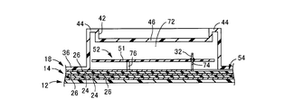
- Cross-sectional explanatory drawing for demonstrating the mounting state of the electronic control unit using a built-in upper case.
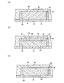
- Cross-sectional explanatory drawing for demonstrating the shaping
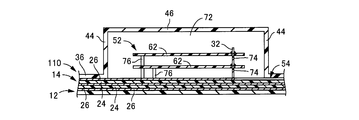
- Cross-sectional explanatory drawing for demonstrating the different aspect of a built-in upper case.
- FIG. 1 schematically shows an overall configuration of a fuse box 10 according to an electronic control unit mounting type electric junction box as one embodiment of the present invention.
- the fuse box 10 includes a lower case 12 and a bus bar laminated body 14, and an external upper case 16 and a built-in upper case 18 as an upper case combined therewith.
- the vertical direction refers to the vertical direction in FIG. 1 unless otherwise specified.
- the lower case 12 is made of a synthetic resin injection-molded body and has a substantially box shape opening upward. Further, a locking claw 22 is formed on the outer peripheral surface of the lower case 12 so as to protrude. Although not shown, a through hole is formed in the bottom wall of the lower case 12 as needed, and a tab protruding below the bus bar laminated body 14 protrudes into the lower external space of the lower case 12 through the through hole. It has become so.
- the bus bar laminate 14 has a laminated structure in which a plurality of bus bars 26 as conductive paths are laminated via an insulating plate 24, and a flat tab formed by the bus bar 26 protrudes upward or downward.
- a fuse connection tab 28, a connector connection tab 30, an electronic control unit connection tab 32, and the like are formed so as to protrude above the bus bar laminated body 14.
- the bus bar laminate 14 is accommodated in the lower case 12.
- the bus bar laminated body 14 is an internal circuit composed of a combination of the bus bar 26 and the insulating plate 24.
- the internal circuit is composed of electric wires (covered wires, bare wires, etc.), flexible printed wiring boards, rigid prints. Arbitrary combinations may be applied to the wiring board by interconnections such as press-fit terminals, press-contact terminals, and welding.
- an external upper case 16 and a built-in upper case 18 are selectively attached to the lower case 12 containing the bus bar laminated body 14.
- the external upper case 16 and the built-in upper case 18 have substantially the same structure in the basic portion except the bottom wall 46 of the concave accommodating portion 42 described later.
- the upper case 16 will be described as an example.
- the same portions as those of the external upper case 16 are denoted by the same reference numerals in the drawing, and the description thereof is omitted.
- the external upper case 16 is made of a synthetic resin injection-molded body and has a substantially box shape that opens downward.
- the external upper case 16 is formed to be slightly larger than the lower case 12, and an engagement recess 34 that opens to the inner surface of the external upper case 16 is formed at a position corresponding to the locking claw 22 of the lower case 12. Is formed. Then, the outer upper case 16 is covered with the lower case 12, and the engaging claw 22 of the lower case 12 and the engaging recess 34 of the outer upper case 16 engage with each other, whereby the outer upper case 16 becomes lower. 12 is fixed to the lock.
- the upper wall 36 of the external upper case 16 is integrally formed with a fuse mounting portion 38, a connector mounting portion 40, and the like, and the fuse connection tab 28 of the bus bar laminated body 14 is placed in the fuse mounting portion 38.
- the connection tabs 30 protrude into the connector mounting portions 40, respectively.
- a fuse (not shown) is attached to the fuse attachment portion 38 to connect the fuse connection tab 28 and the fuse, while a connector such as a wire harness (not shown) is connected to the connector attachment portion 40 to connect the connector connection tab. 30 is electrically connected to the external wiring.
- the external upper case 16 is integrally formed with a concave accommodating portion 42 that opens to the outer surface of the case.
- the concave accommodating portion 42 is a concave portion that is surrounded by a peripheral wall 44 that protrudes upward from the upper wall 36 and has a rectangular shape that opens upward toward the outside of the case, and is a general external electronic control unit 50. It is formed with a size that can accommodate (described later).
- a tab insertion hole 48 is provided in the bottom wall 46 of the concave accommodating portion 42 in the thickness direction.
- the bottom wall 46 is formed on substantially the same plane as the upper wall 36 of the external upper case 16.
- the built-in upper case 18 is different from the external upper case 16 in the basic portion except that the bottom wall 46 of the concave housing portion 42 in the external upper case 16 is raised upwards to be outside the case. It has a common structure.
- the external upper case 16 and the built-in upper case 18 can be combined with the common lower case 12 and the bus bar laminated body 14.
- the outer upper case 16 and the built-in upper case 18 can be combined with the lower case 12 containing the bus bar laminated body 14.
- FIG. 2 schematically shows a mounting state of the external electronic control unit 50 using the external upper case 16.
- a casing 54 serving as an internal space is formed between the external upper case 16 and the lower case 12 by covering the external upper case 16 with the lower case 12.
- the bus bar laminated body 14 is accommodated therein.
- Each tab protruding above the bus bar laminated body 14 is protruded to the outside of the casing 54 through a through hole provided in the upper wall 36 of the external upper case 16, and in particular, electronic control.
- the unit connection tab 32 protrudes into the concave accommodating portion 42 through a tab insertion hole 48 formed in the bottom wall 46 of the concave accommodating portion 42. In this way, when the external upper case 16 is selected and combined, the electric junction box main body is configured including the lower case 12, the bus bar laminated body 14, and the external upper case 16.
- a mounting space for the electronic control unit is formed by the concave accommodating portion 42 that is outside the external upper case 16.
- the external electronic control unit 50 is attached to the concave housing portion 42.
- the external electronic control unit 50 has a structure in which a printed wiring board 62 having various electronic components and printed wiring is housed in a housing 60 formed by combining an upper case 56 and a lower case 58. .
- the lower case 58 is provided with a connector connection hole 64, a connector 66 is provided on one surface of the printed wiring board 62, and a tab through hole at a position facing the connector connection hole 64 on the other surface. 69 is provided.
- the printed wiring board 62 is supported in the housing 60 by, for example, being screwed to a boss 67 projecting from the lower case 58. Further, a locking claw 68 (see FIG.
- the electronic control unit connection tab 32 protruding into the concave accommodating portion 42 is printed through the connector connection hole 64. It is inserted into a connector 66 provided on the wiring board 62. Accordingly, the printed wiring provided on the bus bar 26 and the printed wiring board 62 is electrically connected, and each electronic component provided on the printed wiring board 62 can be electrically connected to the external wiring via the bus bar 26. Is done.
- FIG. 3 schematically shows a mounting state of the built-in electronic control unit 52 using the built-in upper case 18.
- the electric junction box main body is configured including the lower case 12, the bus bar laminated body 14, and the built-in upper case 18.
- the electric junction box main body is configured including the lower case 12, the bus bar laminated body 14, and the built-in upper case 18.
- An accommodation space 72 is formed as a mounting space for the electronic control unit, and the electronic control unit connection tab 32 and the built-in electronic control unit 52 are accommodated in the accommodation space 72.
- the built-in electronic control unit 52 is constituted by a printed wiring board 51 having no housing 60 without being protected by upper and lower cases 56 and 58 like the external electronic control unit 50. Various electronic components and printed wiring provided in 51 are exposed to the outside.
- the electronic control unit connection tab 32 is inserted into a through hole 74 penetrating the printed wiring board 51 as the internal electronic control unit 52 and soldered, whereby the internal electronic control unit 52 is electrically connected. It is attached to the box body in a built-in state in the accommodation space 72. Thereby, the bus bar 26 and the printed wiring board 51 are electrically connected, and each electronic component provided in the built-in electronic control unit 52 can be electrically connected to the external wiring via the bus bar 26.
- the built-in electronic control unit 52 is in a state of being soldered to the electronic control unit connection tab 32, and the electronic control unit connection tab 32 extends along the outer periphery of the printed wiring board 51 on the entire circumference or two diagonal sides.
- the printed wiring board 51 is attached by the support protrusion 76 etc. which are provided in arbitrary places, such as the insulation board 24 of the bus-bar laminated body 14. It is preferable to support.
- an external upper case 16 and a built-in upper case 18 are appropriately selected and combined, so that a common lower case 12 and bus bar laminated body 14 can be used.
- Either the attached electronic control unit 50 or the built-in electronic control unit 52 can be mounted.
- the number of parts can be reduced, manufacturing costs can be reduced, and parts management can be facilitated.
- the external electronic control unit 50 is employed, the external upper case 16 is selected and easily attached, while when the internal electronic control unit 52 is employed, the internal upper case 18 is selected.
- the built-in electronic control unit 52 By soldering the built-in electronic control unit 52 to the electronic control unit connection tab 32, the number of components such as connectors can be reduced, and the electronic control unit can be appropriately selected according to the adoption method of the electronic control unit. Can be attached to the electrical junction box.
- the external upper case 16 and the built-in upper case 18 are suitably molded by an injection molding method or the like using, for example, a molding die schematically showing a molding portion of the concave housing portion 42 in FIG.
- an upper base mold 82 and a lower base mold 84 as a base molding mold, and a telescopic mold
- An upper insert mold 86 is used as a mold.
- the upper base mold 82 is formed with a molding surface 88 corresponding to the upper surface shape of the external upper case 16 excluding the concave accommodating portion 42.
- the lower base mold 84 is formed with a molding surface 90 corresponding to the lower surface shape of the external upper case 16 excluding the concave accommodating portion 42.
- an upper insert mold 86 is detachably attached to a molding portion of the concave housing portion 42 in the upper base mold 82.
- the upper insert mold 86 is formed with a molding surface 92 corresponding to the inner surface shape of the concave accommodating portion 42, and is concave depending on the height dimension of the upper insert mold 86 (the vertical dimension in FIG. 4).
- the depth dimension of the accommodating part 42 is set.
- the upper base mold 82 and the lower base mold 84 to which the upper insert mold 86 is assembled are closed with each other, whereby the molding surface 88 of the upper base mold 82 and the lower base mold 84 are molded.
- a molding cavity 94 having a shape corresponding to the external upper case 16 is formed between the surfaces 90.
- the upper insert mold 86 enters the recess 96 formed in the portion corresponding to the concave accommodating portion 42 on the molding surface 90 of the lower base mold 84, and the upper insert mold 86 is molded.
- a shape corresponding to the bottom wall 46 of the concave accommodating portion 42 is formed between the surface 92 and the concave portion 96 of the lower base mold 84.
- an upper base mold 82 and a lower base mold 84 as a base molding mold, and a nested mold
- the upper insert mold 98 and the lower insert mold 100 are used.
- the upper base mold 82 and the lower base mold 84 the same ones used when the external upper case 16 is molded are used.
- the height of the upper insert mold 98 is smaller than that of the upper insert mold 86 used for molding the external upper case 16.
- the lower insert mold 100 is detachably attached to the lower base mold 84, and a molding surface 102 corresponding to the shape of the inner side surface of the built-in upper case 18 in the concave housing portion 42 is formed. .
- the bottom insert position of the recess 96 is raised by fitting the lower insert mold 100 into the recess 96.
- the upper base mold 82 assembled with the upper insert mold 98 and the lower base mold 84 assembled with the lower insert mold 100 are closed with each other, thereby corresponding to the built-in upper case 18.
- a molding cavity 94 having a shape to be formed is formed.
- the built-in upper case 18 in which the position of the bottom wall 46 is raised as compared with the external upper case 16 is formed. The Then, by preparing a plurality of upper insert molds 98 and lower insert molds 100 having different height dimensions, and selecting and using them appropriately, the raising of the bottom wall 46 can be adjusted.
- a plurality of types of external upper case 16 and built-in upper case 18 having different heights of the bottom wall 46 are molded using the common upper base mold 82 and lower base mold 84. I can do it. As a result, the manufacturing cost can be reduced and the management of the mold can be made easier.
- the bottom wall 46 is raised to the same position as the upper end surface of the peripheral wall 44 by using only the lower insert mold 106 that fills the entire recess 96. Is also possible.
- the embodiment of the present invention has been described. For example, it is sufficient that at least one external upper case and one internal upper case are prepared, but the raising of the bottom wall 46 is set in a plurality of stages. A plurality of types of upper cases may be prepared as necessary. Further, the number of printed wiring boards accommodated in the built-in upper case is not particularly limited. Therefore, for example, as shown in FIG. 5 as a model, a plurality of printed wiring boards 62 are provided in the accommodation space 72 by using the built-in upper case 110 in which the bottom wall 46 is raised to a position substantially equal to the upper end surface of the peripheral wall 44. May be accommodated.
- Such a built-in upper case 110 can be advantageously formed using the lower insert mold 106 shown in FIG.
- the electronic control unit is mounted on the upper case side, but it may be mounted on the lower case side. In this case, an external lower case and a built-in lower case may be formed.
- the fuse box is exemplified as the electrical connection box, but it is of course possible to apply the present invention to a relay box, a junction box or the like.
- 10 fuse box (electrical connection box), 12: lower case, 16: external upper case, 18: upper case for internal use, 26: bus bar (conductive path), 42: concave housing portion, 46: bottom wall, 50: Externally attached electronic control unit, 52: Built-in electronic control unit, 54: Casing, 60: Housing, 72: Storage space (mounting space), 86, 98: Upper insert mold, 100, 106: Lower insert Mold
Landscapes
- Engineering & Computer Science (AREA)
- Mechanical Engineering (AREA)
- Architecture (AREA)
- Civil Engineering (AREA)
- Structural Engineering (AREA)
- Connection Or Junction Boxes (AREA)
Abstract
Description
Claims (2)
- ロアケースとアッパケースを組み合わせたケーシング内に導電路を設けた電気接続箱本体に対して電子制御ユニットが装着されており、該電子制御ユニットが前記電気接続箱本体の前記導電路に接続される電子制御ユニット搭載型の電気接続箱において、
前記電気接続箱本体に対する前記電子制御ユニットの装着スペースが前記アッパケースの外面に開口する凹状収容部によって外部に形成された外付用アッパケースと、該外付用アッパケースにおける前記凹状収容部の底壁を外方に嵩上げすることで前記電子制御ユニットの装着スペースが内部に形成された内蔵用アッパケースとを、前記凹状収容部の底壁位置を除く基本部分において共通化させると共に、それら外付用アッパケースと内蔵用アッパケースに組み合わされる前記ロアケース及び前記導電路を共通化させて、前記電気接続箱本体において前記外付用アッパケースと前記内蔵用アッパケースとを選択的に採用することにより、ハウジングを備えた外付用の前記電子制御ユニットと、ハウジングを備えない内蔵用の電子制御ユニットとを、何れも装着可能としたことを特徴とする電子制御ユニット搭載型の電気接続箱。 - 前記外付用アッパケースと前記内蔵用アッパケースは、同じベース成形金型を用いて製造されており、前記外付用アッパケースの成形金型における前記凹状収容部の底壁の成形部分に入子構造の金型を採用し、前記入子金型を選択することによって前記凹状収容部の底壁の嵩上げが設定されている請求項1に記載の電子制御ユニット搭載型の電気接続箱。
Priority Applications (3)
| Application Number | Priority Date | Filing Date | Title |
|---|---|---|---|
| JP2010550348A JP5051308B2 (ja) | 2009-02-16 | 2009-08-19 | 電子制御ユニット搭載型の電気接続箱 |
| US13/143,625 US8537565B2 (en) | 2009-02-16 | 2009-08-19 | Electronic control unit-mounting electric junction box |
| DE112009004367T DE112009004367T5 (de) | 2009-02-16 | 2009-08-19 | Elektrischer verteilerkasten zur anordnung einer elektronischen steuereinheit |
Applications Claiming Priority (2)
| Application Number | Priority Date | Filing Date | Title |
|---|---|---|---|
| JP2009-032688 | 2009-02-16 | ||
| JP2009032688 | 2009-02-16 |
Publications (1)
| Publication Number | Publication Date |
|---|---|
| WO2010092633A1 true WO2010092633A1 (ja) | 2010-08-19 |
Family
ID=42561487
Family Applications (1)
| Application Number | Title | Priority Date | Filing Date |
|---|---|---|---|
| PCT/JP2009/003948 Ceased WO2010092633A1 (ja) | 2009-02-16 | 2009-08-19 | 電子制御ユニット搭載型の電気接続箱 |
Country Status (4)
| Country | Link |
|---|---|
| US (1) | US8537565B2 (ja) |
| JP (1) | JP5051308B2 (ja) |
| DE (1) | DE112009004367T5 (ja) |
| WO (1) | WO2010092633A1 (ja) |
Cited By (2)
| Publication number | Priority date | Publication date | Assignee | Title |
|---|---|---|---|---|
| CN102340118A (zh) * | 2011-07-06 | 2012-02-01 | 宁波正耀汽车电器有限公司 | 底盘配电总成 |
| JP2013085341A (ja) * | 2011-10-07 | 2013-05-09 | Sumitomo Wiring Syst Ltd | 電気接続箱 |
Families Citing this family (5)
| Publication number | Priority date | Publication date | Assignee | Title |
|---|---|---|---|---|
| GB2508402B (en) * | 2012-11-30 | 2015-05-27 | Control Tech Ltd | A mount for electrical equipment |
| USD738326S1 (en) * | 2014-02-09 | 2015-09-08 | Prettl Electric Corporation | Switch housing platform |
| USD738327S1 (en) * | 2014-02-09 | 2015-09-08 | Prettl Electric Corporation | Switch housing platform |
| US10673218B2 (en) * | 2017-08-17 | 2020-06-02 | Thomas & Betts International Llc | Molded electrical junction box |
| JP6797875B2 (ja) * | 2018-10-03 | 2020-12-09 | 住友電装株式会社 | 電気接続箱 |
Citations (3)
| Publication number | Priority date | Publication date | Assignee | Title |
|---|---|---|---|---|
| JP2000306636A (ja) * | 1999-04-19 | 2000-11-02 | Harness Syst Tech Res Ltd | 電子ユニットの取付構造 |
| JP2004048969A (ja) * | 2002-07-16 | 2004-02-12 | Yazaki Corp | 電気接続箱 |
| JP2007282385A (ja) * | 2006-04-07 | 2007-10-25 | Sumitomo Wiring Syst Ltd | 車載用の電気接続箱 |
Family Cites Families (5)
| Publication number | Priority date | Publication date | Assignee | Title |
|---|---|---|---|---|
| JPH10174253A (ja) | 1996-12-06 | 1998-06-26 | Yazaki Corp | 電気接続箱 |
| JP4234259B2 (ja) * | 1999-05-14 | 2009-03-04 | 富士通テン株式会社 | 電子機器の組合せ構造 |
| JP2001196770A (ja) * | 2000-01-12 | 2001-07-19 | Omron Corp | コントロールユニット |
| JP2002058134A (ja) * | 2000-08-09 | 2002-02-22 | Auto Network Gijutsu Kenkyusho:Kk | 電子制御ユニットの搭載構造 |
| CN101932488B (zh) * | 2008-01-25 | 2013-07-03 | 三菱电机株式会社 | 电动式动力转向装置 |
-
2009
- 2009-08-19 WO PCT/JP2009/003948 patent/WO2010092633A1/ja not_active Ceased
- 2009-08-19 JP JP2010550348A patent/JP5051308B2/ja not_active Expired - Fee Related
- 2009-08-19 DE DE112009004367T patent/DE112009004367T5/de not_active Withdrawn
- 2009-08-19 US US13/143,625 patent/US8537565B2/en not_active Expired - Fee Related
Patent Citations (3)
| Publication number | Priority date | Publication date | Assignee | Title |
|---|---|---|---|---|
| JP2000306636A (ja) * | 1999-04-19 | 2000-11-02 | Harness Syst Tech Res Ltd | 電子ユニットの取付構造 |
| JP2004048969A (ja) * | 2002-07-16 | 2004-02-12 | Yazaki Corp | 電気接続箱 |
| JP2007282385A (ja) * | 2006-04-07 | 2007-10-25 | Sumitomo Wiring Syst Ltd | 車載用の電気接続箱 |
Cited By (3)
| Publication number | Priority date | Publication date | Assignee | Title |
|---|---|---|---|---|
| CN102340118A (zh) * | 2011-07-06 | 2012-02-01 | 宁波正耀汽车电器有限公司 | 底盘配电总成 |
| JP2013085341A (ja) * | 2011-10-07 | 2013-05-09 | Sumitomo Wiring Syst Ltd | 電気接続箱 |
| EP2579409A3 (en) * | 2011-10-07 | 2014-11-19 | Sumitomo Wiring Systems, Ltd. | Electric connection box |
Also Published As
| Publication number | Publication date |
|---|---|
| US8537565B2 (en) | 2013-09-17 |
| JPWO2010092633A1 (ja) | 2012-08-16 |
| JP5051308B2 (ja) | 2012-10-17 |
| DE112009004367T5 (de) | 2012-05-24 |
| US20110267786A1 (en) | 2011-11-03 |
Similar Documents
| Publication | Publication Date | Title |
|---|---|---|
| JP5051308B2 (ja) | 電子制御ユニット搭載型の電気接続箱 | |
| US6430054B1 (en) | Electrical junction box | |
| JP5130110B2 (ja) | 電気接続箱 | |
| US10063041B2 (en) | Electronic component unit | |
| CN105896422B (zh) | 汇流条板、电子元器件单元和线束 | |
| JP2015208124A (ja) | インサートバスバープレート及びその製造方法 | |
| US6835073B2 (en) | Junction box | |
| US6364670B1 (en) | Junction box having function electronics | |
| JP2006320147A (ja) | 電気接続箱 | |
| US7132600B2 (en) | Electric connection box | |
| CN105896206A (zh) | 汇流条板、电子元器件单元和线束 | |
| JP5156499B2 (ja) | 電気接続箱 | |
| JP2010199514A (ja) | 回路構成体 | |
| KR20120018843A (ko) | 자동차용 정션박스 | |
| JP3698033B2 (ja) | ジャンクションボックス | |
| JP2012010590A (ja) | 電気接続箱 | |
| JP3465784B2 (ja) | 電気接続箱 | |
| JP2007295787A (ja) | 電気接続箱 | |
| JP2024101358A (ja) | コネクタ | |
| JP3330864B2 (ja) | 電気接続箱 | |
| JP2006062599A (ja) | 電装品制御システム及び電気接続箱 | |
| JP4340222B2 (ja) | 電気接続箱 | |
| JPH09117037A (ja) | 電気接続箱 | |
| JPH0613330U (ja) | 電気接続箱 | |
| JP2011155735A (ja) | 回路構成体、回路構成体の製造方法、および電気接続箱 |
Legal Events
| Date | Code | Title | Description |
|---|---|---|---|
| 121 | Ep: the epo has been informed by wipo that ep was designated in this application |
Ref document number: 09839956 Country of ref document: EP Kind code of ref document: A1 |
|
| ENP | Entry into the national phase |
Ref document number: 2010550348 Country of ref document: JP Kind code of ref document: A |
|
| WWE | Wipo information: entry into national phase |
Ref document number: 13143625 Country of ref document: US |
|
| WWE | Wipo information: entry into national phase |
Ref document number: 1120090043674 Country of ref document: DE Ref document number: 112009004367 Country of ref document: DE |
|
| 122 | Ep: pct application non-entry in european phase |
Ref document number: 09839956 Country of ref document: EP Kind code of ref document: A1 |