WO2010090190A1 - Laser exposure device - Google Patents
Laser exposure device Download PDFInfo
- Publication number
- WO2010090190A1 WO2010090190A1 PCT/JP2010/051447 JP2010051447W WO2010090190A1 WO 2010090190 A1 WO2010090190 A1 WO 2010090190A1 JP 2010051447 W JP2010051447 W JP 2010051447W WO 2010090190 A1 WO2010090190 A1 WO 2010090190A1
- Authority
- WO
- WIPO (PCT)
- Prior art keywords
- fly
- eye lens
- laser light
- lens
- laser
- Prior art date
Links
Images


Classifications
-
- H—ELECTRICITY
- H01—ELECTRIC ELEMENTS
- H01L—SEMICONDUCTOR DEVICES NOT COVERED BY CLASS H10
- H01L21/00—Processes or apparatus adapted for the manufacture or treatment of semiconductor or solid state devices or of parts thereof
- H01L21/02—Manufacture or treatment of semiconductor devices or of parts thereof
- H01L21/027—Making masks on semiconductor bodies for further photolithographic processing not provided for in group H01L21/18 or H01L21/34
- H01L21/0271—Making masks on semiconductor bodies for further photolithographic processing not provided for in group H01L21/18 or H01L21/34 comprising organic layers
- H01L21/0273—Making masks on semiconductor bodies for further photolithographic processing not provided for in group H01L21/18 or H01L21/34 comprising organic layers characterised by the treatment of photoresist layers
- H01L21/0274—Photolithographic processes
- H01L21/0275—Photolithographic processes using lasers
-
- G—PHYSICS
- G02—OPTICS
- G02B—OPTICAL ELEMENTS, SYSTEMS OR APPARATUS
- G02B19/00—Condensers, e.g. light collectors or similar non-imaging optics
- G02B19/0004—Condensers, e.g. light collectors or similar non-imaging optics characterised by the optical means employed
- G02B19/0009—Condensers, e.g. light collectors or similar non-imaging optics characterised by the optical means employed having refractive surfaces only
- G02B19/0014—Condensers, e.g. light collectors or similar non-imaging optics characterised by the optical means employed having refractive surfaces only at least one surface having optical power
-
- G—PHYSICS
- G02—OPTICS
- G02B—OPTICAL ELEMENTS, SYSTEMS OR APPARATUS
- G02B19/00—Condensers, e.g. light collectors or similar non-imaging optics
- G02B19/0033—Condensers, e.g. light collectors or similar non-imaging optics characterised by the use
- G02B19/0047—Condensers, e.g. light collectors or similar non-imaging optics characterised by the use for use with a light source
- G02B19/0052—Condensers, e.g. light collectors or similar non-imaging optics characterised by the use for use with a light source the light source comprising a laser diode
-
- G—PHYSICS
- G02—OPTICS
- G02B—OPTICAL ELEMENTS, SYSTEMS OR APPARATUS
- G02B27/00—Optical systems or apparatus not provided for by any of the groups G02B1/00 - G02B26/00, G02B30/00
- G02B27/09—Beam shaping, e.g. changing the cross-sectional area, not otherwise provided for
- G02B27/0927—Systems for changing the beam intensity distribution, e.g. Gaussian to top-hat
-
- G—PHYSICS
- G02—OPTICS
- G02B—OPTICAL ELEMENTS, SYSTEMS OR APPARATUS
- G02B27/00—Optical systems or apparatus not provided for by any of the groups G02B1/00 - G02B26/00, G02B30/00
- G02B27/09—Beam shaping, e.g. changing the cross-sectional area, not otherwise provided for
- G02B27/0938—Using specific optical elements
- G02B27/095—Refractive optical elements
- G02B27/0955—Lenses
- G02B27/0961—Lens arrays
-
- G—PHYSICS
- G03—PHOTOGRAPHY; CINEMATOGRAPHY; ANALOGOUS TECHNIQUES USING WAVES OTHER THAN OPTICAL WAVES; ELECTROGRAPHY; HOLOGRAPHY
- G03F—PHOTOMECHANICAL PRODUCTION OF TEXTURED OR PATTERNED SURFACES, e.g. FOR PRINTING, FOR PROCESSING OF SEMICONDUCTOR DEVICES; MATERIALS THEREFOR; ORIGINALS THEREFOR; APPARATUS SPECIALLY ADAPTED THEREFOR
- G03F7/00—Photomechanical, e.g. photolithographic, production of textured or patterned surfaces, e.g. printing surfaces; Materials therefor, e.g. comprising photoresists; Apparatus specially adapted therefor
- G03F7/70—Microphotolithographic exposure; Apparatus therefor
- G03F7/70058—Mask illumination systems
- G03F7/70083—Non-homogeneous intensity distribution in the mask plane
-
- G—PHYSICS
- G03—PHOTOGRAPHY; CINEMATOGRAPHY; ANALOGOUS TECHNIQUES USING WAVES OTHER THAN OPTICAL WAVES; ELECTROGRAPHY; HOLOGRAPHY
- G03F—PHOTOMECHANICAL PRODUCTION OF TEXTURED OR PATTERNED SURFACES, e.g. FOR PRINTING, FOR PROCESSING OF SEMICONDUCTOR DEVICES; MATERIALS THEREFOR; ORIGINALS THEREFOR; APPARATUS SPECIALLY ADAPTED THEREFOR
- G03F7/00—Photomechanical, e.g. photolithographic, production of textured or patterned surfaces, e.g. printing surfaces; Materials therefor, e.g. comprising photoresists; Apparatus specially adapted therefor
- G03F7/70—Microphotolithographic exposure; Apparatus therefor
- G03F7/70058—Mask illumination systems
- G03F7/70191—Optical correction elements, filters or phase plates for controlling intensity, wavelength, polarisation, phase or the like
-
- G—PHYSICS
- G03—PHOTOGRAPHY; CINEMATOGRAPHY; ANALOGOUS TECHNIQUES USING WAVES OTHER THAN OPTICAL WAVES; ELECTROGRAPHY; HOLOGRAPHY
- G03F—PHOTOMECHANICAL PRODUCTION OF TEXTURED OR PATTERNED SURFACES, e.g. FOR PRINTING, FOR PROCESSING OF SEMICONDUCTOR DEVICES; MATERIALS THEREFOR; ORIGINALS THEREFOR; APPARATUS SPECIALLY ADAPTED THEREFOR
- G03F7/00—Photomechanical, e.g. photolithographic, production of textured or patterned surfaces, e.g. printing surfaces; Materials therefor, e.g. comprising photoresists; Apparatus specially adapted therefor
- G03F7/70—Microphotolithographic exposure; Apparatus therefor
- G03F7/70483—Information management; Active and passive control; Testing; Wafer monitoring, e.g. pattern monitoring
- G03F7/7055—Exposure light control in all parts of the microlithographic apparatus, e.g. pulse length control or light interruption
- G03F7/70583—Speckle reduction, e.g. coherence control or amplitude/wavefront splitting
Definitions
- the present invention relates to a laser exposure apparatus including a fly-eye lens in which a plurality of condensing lenses are arranged in a plane substantially orthogonal to the optical axis of laser light, and more specifically, interference fringes of laser light generated by the fly-eye lens. And a laser exposure apparatus that enables uniform exposure by reducing illuminance unevenness of laser light.
- a conventional laser exposure apparatus includes a beam expander that expands the diameter of the laser beam and a fly that equalizes the intensity distribution of the laser beam with the expanded diameter in order to uniformly irradiate the object with the laser beam.
- Optical integrators such as eye lenses are used.
- an optical path difference adjusting member is provided between the beam expander and the fly-eye lens in order to reduce interference fringes caused by interference of the light transmitted through the fly-eye lens due to the coherency of the laser light.
- the optical path difference adjusting member is provided only between the beam expander and the fly-eye lens, so that the interference fringes due to the transmitted light of the fly-eye lens are completely removed.
- the present invention addresses such problems, averages the interference fringes of the laser light produced by the fly-eye lens, and reduces the unevenness of the illuminance of the laser light to enable uniform exposure.
- the purpose is to provide.
- a laser exposure apparatus includes a laser light source that emits laser light and a plurality of lenses arranged in a plane substantially orthogonal to the optical axis of the laser light, and temporarily emits emitted light.
- a first fly-eye lens that diverges radially after condensing and expands a cross-sectional shape of the laser light; and a first fly-eye lens disposed on the laser light incident side of the first fly-eye lens.
- First phase difference generating means for generating a phase difference in the laser light respectively incident on each of the condenser lenses, and a condenser for emitting the first fly-eye lens and converting the laser light having an enlarged cross-sectional shape into parallel light
- a second fly-eye that has a lens and a plurality of lenses arranged side by side in a plane substantially orthogonal to the optical axis of the condenser lens, and uniformizes the light intensity distribution in the illumination area of the photomask by the laser light.
- a second phase difference occurrence that causes a phase difference in the laser light that is disposed on the laser light incident side of the second fly-eye lens and is incident on each condenser lens of the second fly-eye lens.
- laser light is radiated from the laser light source, and incident on the first phase difference generating means disposed on the laser light incident side of the first fly-eye lens without expanding the beam diameter
- the first phase difference generating means generates a phase difference between the laser beams respectively incident on the plurality of condensing lenses arranged in a plane substantially orthogonal to the optical axis of the first fly-eye lens.
- the coherency of the laser light emitted from the fly-eye lens is reduced, the light emitted from each condenser lens is once condensed by the first fly-eye lens, and then diverged radially to expand the cross-sectional shape of the laser light.
- the laser light whose cross-sectional shape is enlarged by the lens is converted into parallel light, and the second fly-eye lens is arranged on the optical axis of the second fly-eye lens by the second phase difference generating means arranged on the laser light incident side of the second fly-eye lens.
- the second phase difference generating means arranged on the laser light incident side of the second fly-eye lens.
- Nearly orthogonal plane A phase difference is caused in the laser light respectively incident on the plurality of condensing lenses arranged side by side to reduce the coherency of the laser light emitted from the second fly-eye lens again, and the second fly-eye lens reduces the light intensity.
- the photomask is irradiated with a uniform distribution.
- a transparent parallel plane rotating plate that is inclined with respect to the optical axis and rotates about the optical axis is provided on the laser beam incident side of the condenser lens.
- a laser which is provided on the laser beam incident side of the condenser lens and is rotated around the optical axis of the transparent parallel plane rotating plate arranged to be inclined with respect to the optical axis and incident on the second fly-eye lens. The incident angle of light is changed.
- the first and second phase difference generating means are used for the plurality of laser beams respectively incident on the condensing lenses of the first and second raiai lenses. Since the phase difference is generated and the coherency of the laser light emitted from the first and second fly-eye lenses is reduced, interference fringes generated in the illumination area can be reduced as compared with the prior art. Further, as compared with the case where one fly-eye lens is used, the intensity distribution of the laser light can be made more uniform, and the illuminance unevenness can be further reduced. Therefore, the photomask can be uniformly illuminated to enable uniform exposure, and a fine pattern can be easily exposed on the object to be exposed. In addition, since the first fly-eye lens has both a laser beam homogenizing function and a beam diameter expanding function, it is not necessary to provide a separate beam expander, and the number of parts can be reduced.
- the incident angle of the laser beam incident on the second fly-eye lens can be changed during exposure. Therefore, the illumination area on the photomask by the laser light emitted from each condensing lens of the second fly-eye lens can be finely moved in accordance with the rotation of the parallel plane rotating plate, and is generated in the illumination area on the photomask.
- the interference fringes of the laser light can be averaged and made inconspicuous. Thereby, the illumination intensity nonuniformity of a laser beam can be reduced further, and a to-be-exposed body can be exposed more uniformly.
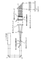
- FIG. 1 is a front view showing a first embodiment of a laser exposure apparatus according to the present invention.
- This laser exposure apparatus exposes an object to be exposed by irradiating a laser beam through a photomask, and includes a laser light source 1, a first fly-eye lens 2, a first optical path difference adjusting member 3, A first condenser lens 4, a parallel plane rotating plate 5, a second fly's eye lens 6, a second optical path difference adjusting member 7, and a second condenser lens 8 are provided.
- the laser light source 1 is an ultraviolet pulse laser oscillator, and an excimer laser or a YAG laser can be used.
- a first fly-eye lens 2 is provided in front of the laser light source 1 in the radiation direction of the laser light.
- the first fly-eye lens 2 once functions to condense the laser light emitted from the laser light source 1 and then diverge it radially to expand the cross-sectional shape of the laser light.
- the light intensity distribution in the incident side surface of the second fly's eye lens 6 is made uniform, and a plurality of condensing lenses 2a are arranged in a plane substantially orthogonal to the optical axis of the laser beam, for example, 3 vertical ⁇ 3 horizontal. They are arranged in a matrix.
- a first optical path difference adjusting member 3 is provided on the laser light incident side of the first fly-eye lens 2.
- the first optical path difference adjusting member 3 reduces the coherency of the laser light emitted from the first fly-eye lens 2 and emits a plurality of laser lights emitted from the respective condensing lenses 2 a of the first fly-eye lens 2. Is to suppress interference on the incident side surface of the second fly-eye lens 6, and a phase difference is applied to a plurality of laser beams respectively incident on the condenser lenses 2 a of the first fly-eye lens 2. This is the first phase difference generating means to be generated.
- the first optical path difference adjusting member 3 is different in length in the axial direction parallel to the optical axis and has a refractive index of 1 corresponding to each condenser lens 2a of the first fly-eye lens 2.
- a larger rod-shaped transparent member 3a such as quartz glass or transparent glass, is provided, and the optical path lengths of a plurality of laser beams respectively incident on the condenser lenses 2a of the first fly-eye lens 2 are provided. It plays a function of changing.
- a first condenser lens 4 is provided on the downstream side of the first fly-eye lens 2 in the traveling direction of the laser light.
- the first condenser lens 4 is a plano-convex lens in which the radial laser beam emitted from the first fly-eye lens 2 is converted into parallel light, and the light incident side is flat.
- the first fly-eye lens 2 is arranged so as to substantially match the rear focal position.
- a parallel plane rotating plate 5 is provided on the optical path between the first fly-eye lens 2 and the first condenser lens 4.
- the plane-parallel rotating plate 5 is for changing the incident angle of laser light incident on a second fly's eye lens 6 described later, and is provided with a transparent, for example, glass disc tilted with respect to the optical axis. This rotates around the optical axis. Thereby, the illumination area of the laser light on the photomask 9 is finely moved, and the interference fringes of the laser light generated by the second fly-eye lens 6 generated on the photomask 9 are averaged to be inconspicuous. Further, the illuminance unevenness of the laser light emitted from the first fly-eye lens 3 through the first optical path difference adjusting member 3 is reduced.
- FIG. 2 is an explanatory diagram showing the relationship between the position of the plane-parallel rotating plate 5, the incident angle of the laser light incident on the second fly-eye lens 6, and changes in the illumination area on the photomask 9.
- the plane-parallel rotating plate 5 rotates around the optical axis
- the plane-parallel rotating plate 5 reciprocates as indicated by arrows in the front view of FIG.
- the parallel plane rotating plate 5 is located at the position indicated by the solid line in FIG. 5A
- the laser light is refracted by the parallel plane rotating plate 5 as indicated by the solid line, and the laser beam is refracted at a constant incident angle.
- the light enters the condenser lens 6 a of the second fly-eye lens 6.
- the laser light is refracted by the plane-parallel rotating plate 5 as indicated by the broken line, which is different from the above.
- the light enters the condenser lens 6a at an incident angle.
- the illumination area 10 on the photomask 9 illuminated by the laser beam emitted from the second fly-eye lens 6 moves from the area indicated by the solid line to the area indicated by the broken line in FIG.
- the intensity unevenness of the laser light emitted from the first fly-eye lens 2 is reduced.
- the illumination area 10 on the photomask 9 is finely moved, and the light and dark pattern of the interference fringes and the illuminance unevenness generated on the photomask 9 due to the interference of the plurality of laser beams emitted from the second fly-eye lens 6 Can be averaged and made inconspicuous.
- a second fly-eye lens 6 is provided on the downstream side of the first condenser lens 4 in the traveling direction of the laser light.
- the second fly-eye lens 6 makes the light intensity distribution in the illumination area 10 of the photomask 9 uniform, and a plurality of condensing lenses in a plane substantially perpendicular to the optical axis of the first condenser lens 4.
- 6a is arranged in a matrix of, for example, 12 vertical x 4 horizontal, and is a double fly-eye lens in which two identical fly-eye lenses are combined.
- a second optical path difference adjusting member 7 is provided on the laser beam incident side of the second fly-eye lens 6.
- the second optical path difference adjusting member 7 reduces the coherency of the laser light emitted from the second fly-eye lens 6 and emits a plurality of laser lights emitted from the respective condenser lenses 6 a of the second fly-eye lens 6.
- the second optical path difference adjusting member 7 has different lengths in the axial direction parallel to the optical axis, corresponding to the four columns of condensing lenses 6a of the second fly-eye lens 6, respectively.
- a plate-shaped transparent member 7a having a refractive index larger than 1 such as quartz glass or transparent glass is formed by superimposing them in the horizontal direction and vertically incident on each condenser lens 6a of the second fly-eye lens 6. It functions to change the optical optical path length between columns adjacent to each other in the horizontal direction of the laser beams in the columns.
- a second condenser lens 8 is provided on the downstream side of the second fly-eye lens 6 in the traveling direction of the laser light.
- the second condenser lens 8 is used to convert the laser light emitted from the second fly-eye lens 6 into parallel light so as to enter the photomask 9 vertically, and the two light incident sides are flat. It is configured by combining plano-convex lenses, and is arranged such that its front focal position substantially matches the rear focal position of the second fly-eye lens 6.
- reference numerals 11, 12, and 13 denote planar reflection mirrors that bend the optical path.
- the laser light emitted from the laser light source 1 is reflected by the two reflecting mirrors 11 and 12 and enters the first optical path difference adjusting member 3.
- the first optical path difference adjusting member 3 corresponds to each condenser lens 2 a of the first fly-eye lens 2, and has a plurality of refractive indexes greater than 1, each having a different axial length parallel to the optical axis. Therefore, the plurality of laser beams emitted from the plurality of transparent members 3a of the first optical path difference adjusting member 3 are out of phase with each other.
- the plurality of laser beams emitted from the plurality of transparent members 3 a of the first optical path difference adjusting member 3 are respectively incident on the corresponding condensing lenses 2 a of the first fly-eye lens 2.
- the plurality of laser beams emitted from the respective condensing lenses 2a of the first fly-eye lens 2 are condensed at the rear focal points of the respective condensing lenses 3a and then radiate radially.
- the laser beams incident on the condenser lenses 2a of the first fly-eye lens 2 are out of phase with each other, so that the coherency of the laser beams emitted from the first fly-eye lens 2 is reduced. .
- the second fly-eye lens 6 illuminated by the plurality of laser beams emitted from the respective condensing lenses 2a, the interference of the respective laser beams is suppressed, the generation of interference fringes is suppressed, and the second fly-eye lens is suppressed.
- the lens 6 is illuminated substantially uniformly.
- the radial laser beam emitted from the first fly-eye lens 3 is collimated by the first condenser lens 4 and then enters the second fly-eye lens 6 through the second optical path difference adjusting member 7. .
- the laser beam incident side of the first condenser lens 4 is provided with a parallel plane rotating plate 5 in which a transparent disk made of, for example, glass is inclined with respect to the optical axis, and this is centered on the optical axis. Since it is rotating, the position of the chief ray of the laser beam that is refracted by the parallel plane rotating plate 5 and emitted therefrom is incident on the first condenser lens 4 as shown in FIG. 2A. It changes in the radial direction of the lens 4. As a result, the incident angle of the laser light incident on the second fly-eye lens 6 changes as shown in FIG. At the same time, the illuminance unevenness of the laser light incident on the second fly's eye lens 6 is averaged.
- the laser light emitted from the first condenser lens 4 has a second optical path difference formed by combining a plurality of transparent members 7a each having a different axial length parallel to the optical axis and a refractive index larger than 1.
- the second fly-eye lens 6 is illuminated by being divided into a plurality of laser beams.
- the optical optical path length of each laser beam passing through each transparent member 7a of the second optical path difference adjusting member 7 is different, between each laser beam emitting the second optical path difference adjusting member 7, There is a phase difference.
- each condenser lens 6a of the second fly's eye lens 6 is once condensed at the focal point of each condenser lens 6a, and then radiates and enters the plane reflecting mirror 13.
- the laser light is reflected by the plane reflection mirror 13, is then made parallel light by the second condenser lens 8, and enters the photomask 9 substantially perpendicularly to illuminate the photomask 9 uniformly.
- the second optical path difference adjusting member 7 is configured by superimposing plate-like transparent members 7a having different lengths in the optical axis direction and long in the vertical direction in the horizontal direction.
- the laser light having the same phase is incident on the condensing lenses 6a arranged in the vertical direction of the fly-eye lens 6 of No. 2, and the phase of the condensing lenses 6a arranged in the horizontal direction is made incident on the condensing lenses 6a arranged in the horizontal direction. Since different laser beams are incident, the in-phase laser beams emitted from the condenser lenses 6 a arranged in the vertical direction of the second fly-eye lens 6 are incident on the illumination region 10 on the photomask 9.
- the parallel plane rotating plate 5 is provided on the incident side of the first condenser lens 4 and is rotated about its optical axis.
- the incident angle of the laser light incident on the eye lens 6 changes. Therefore, as shown in FIG. 2B, the illumination area 10 by the laser light on the photomask 9 is finely moved, the light and dark patterns of the interference fringes are averaged and become inconspicuous, and the illuminance unevenness of the laser light is averaged. , Uniform exposure can be performed.
- FIG. 3 is a front view showing a second embodiment of the laser exposure apparatus according to the present invention.
- the second embodiment is different from the first embodiment in that a collimation mirror 14 is arranged at the position of the plane reflection mirror 13 in place of the second condenser lens 8.
- the front focal position of the collimation mirror 14 is substantially matched with the rear focal position of the second fly-eye lens 6.
- the laser light emitted from the second fly-eye lens 6 can be converted into parallel light and incident perpendicularly on the photomask 9.
- the second optical path difference adjusting member 7 corresponds to each of the four columns of condensing lenses 6a of the second fly-eye lens 6 and is parallel to the optical axis.
- the plate-like transparent members 7a having different lengths in the axial direction are formed by superimposing them in the lateral direction
- the present invention is not limited to this, and each of the second fly-eye lenses 6 is collected. It may be formed by combining rod-shaped transparent members having different lengths in the axial direction parallel to the optical axis corresponding to the optical lens 6a. In this case, since the phases of the laser beams emitted from the condenser lenses 6a of the second fly-eye lens 6 are all different, the possibility that the laser beams interfere with each other on the photomask 9 is reduced.
- phase difference generating means is an optical path difference adjusting member.
- present invention is not limited to this, and a phase plate provided corresponding to each condenser lens of the fly-eye lens. There may be.
Landscapes
- Physics & Mathematics (AREA)
- General Physics & Mathematics (AREA)
- Optics & Photonics (AREA)
- Exposure And Positioning Against Photoresist Photosensitive Materials (AREA)
- Exposure Of Semiconductors, Excluding Electron Or Ion Beam Exposure (AREA)
- Engineering & Computer Science (AREA)
- Condensed Matter Physics & Semiconductors (AREA)
- Manufacturing & Machinery (AREA)
- Computer Hardware Design (AREA)
- Microelectronics & Electronic Packaging (AREA)
- Power Engineering (AREA)
- Mechanical Optical Scanning Systems (AREA)
Abstract
Description
レーザ光源1から放射されたレーザ光は、二つの反射ミラー11,12で反射されて、第1の光路差調整部材3に入射する。この第1の光路差調整部材3は、第1のフライアイレンズ2の各集光レンズ2aに対応して、光軸に平行な軸方向の長さが夫々異なり屈折率が1よりも大きい複数の透明部材3aを組み合わせて構成したものであるため、第1の光路差調整部材3の複数の透明部材3aを射出する複数のレーザ光は、互いに位相がずれたものとなっている。 Next, the operation of the thus configured laser exposure apparatus will be described.
The laser light emitted from the laser light source 1 is reflected by the two reflecting
2…第1のフライアイレンズ(フライアイレンズ)
2a…第1のフライアイレンズの集光レンズ
3…第1の光路差調整部材(第1の位相差生起手段)
3a…第1の光路差調整部材の透明部材
4…第1のコンデンサーレンズ
5…平行平面回転板
6…第2のフライアイレンズ
6a…第2のフライアイレンズの集光レンズ
7…第2の光路差調整部材(第2の位相差生起手段)
7a…第2の光路差調整部材の透明部材
8…第2のコンデンサーレンズ
9…フォトマスク
10…フォトマスク上の照明領域 DESCRIPTION OF SYMBOLS 1 ... Laser
2a ... Condensing lens of the first fly-
3a: Transparent member of first optical path
7a: Transparent member of second optical path difference adjusting member 8 ...
Claims (2)
- レーザ光を放射するレーザ光源と、
前記レーザ光の光軸に略直交する面内に複数のレンズが並べて配置され、射出光を一旦集光した後、放射状に発散させてレーザ光の断面形状を拡大する第1のフライアイレンズと、
前記第1のフライアイレンズのレーザ光の入射側に配置され、前記第1のフライアイレンズの各集光レンズに夫々入射するレーザ光に位相差を生じさせる第1の位相差生起手段と、
前記第1のフライアイレンズを射出し断面形状が拡大されたレーザ光を平行光にするコンデンサーレンズと、
前記コンデンサーレンズの光軸に略直交する面内に複数のレンズが並べて配置され、レーザ光によるフォトマスクの照明領域内の光強度分布を均一化する第2のフライアイレンズと、
前記第2のフライアイレンズのレーザ光の入射側に配置され、前記第2のフライアイレンズの各集光レンズに夫々入射するレーザ光に位相差を生じさせる第2の位相差生起手段と、
を備えたことを特徴とするレーザ露光装置。 A laser light source that emits laser light;
A first fly-eye lens in which a plurality of lenses are arranged side by side in a plane substantially orthogonal to the optical axis of the laser light, and after converging the emitted light, the first fly-eye lens expands the cross-sectional shape of the laser light by diverging radially; ,
First phase difference generating means that is arranged on the laser beam incident side of the first fly-eye lens and that causes a phase difference in the laser light incident on each condenser lens of the first fly-eye lens;
A condenser lens that emits the first fly-eye lens and converts the laser light having an enlarged cross-sectional shape into parallel light;
A second fly-eye lens in which a plurality of lenses are arranged side by side in a plane substantially orthogonal to the optical axis of the condenser lens, and the light intensity distribution in the illumination area of the photomask by the laser light is made uniform;
Second phase difference generating means disposed on the laser beam incidence side of the second fly's eye lens and causing a phase difference in the laser light respectively incident on each condenser lens of the second fly's eye lens;
A laser exposure apparatus comprising: - 前記コンデンサーレンズのレーザ光の入射側に、光軸に対して傾いて配置され、光軸を中心に回転する透明な平行平面回転板を設けたことを特徴とする請求項1記載のレーザ露光装置。 2. A laser exposure apparatus according to claim 1, wherein a transparent parallel plane rotating plate is provided on the laser beam incident side of the condenser lens so as to be inclined with respect to the optical axis and to rotate about the optical axis. .
Priority Applications (1)
| Application Number | Priority Date | Filing Date | Title |
|---|---|---|---|
| CN2010800064003A CN102308364A (en) | 2009-02-03 | 2010-02-02 | Laser exposure device |
Applications Claiming Priority (2)
| Application Number | Priority Date | Filing Date | Title |
|---|---|---|---|
| JP2009022631A JP5639745B2 (en) | 2009-02-03 | 2009-02-03 | Laser exposure equipment |
| JP2009-022631 | 2009-02-03 |
Publications (1)
| Publication Number | Publication Date |
|---|---|
| WO2010090190A1 true WO2010090190A1 (en) | 2010-08-12 |
Family
ID=42542084
Family Applications (1)
| Application Number | Title | Priority Date | Filing Date |
|---|---|---|---|
| PCT/JP2010/051447 WO2010090190A1 (en) | 2009-02-03 | 2010-02-02 | Laser exposure device |
Country Status (5)
| Country | Link |
|---|---|
| JP (1) | JP5639745B2 (en) |
| KR (1) | KR101634329B1 (en) |
| CN (1) | CN102308364A (en) |
| TW (1) | TWI463270B (en) |
| WO (1) | WO2010090190A1 (en) |
Cited By (3)
| Publication number | Priority date | Publication date | Assignee | Title |
|---|---|---|---|---|
| CN102269936A (en) * | 2011-06-01 | 2011-12-07 | 长春理工大学 | Method and system for simulating moth compound eye optical antireflection structure pattern |
| US9134537B2 (en) | 2011-04-05 | 2015-09-15 | V Technology Co., Ltd. | Laser lighting device |
| US10281730B2 (en) | 2015-10-11 | 2019-05-07 | Dolby Laboratories Licensing Corporation | Optical system for image projectors |
Families Citing this family (5)
| Publication number | Priority date | Publication date | Assignee | Title |
|---|---|---|---|---|
| JP5803222B2 (en) * | 2011-04-05 | 2015-11-04 | 株式会社ブイ・テクノロジー | Laser illumination device |
| JP6002964B2 (en) * | 2012-01-31 | 2016-10-05 | 株式会社ブイ・テクノロジー | Laser illumination device |
| JP6345963B2 (en) * | 2014-03-28 | 2018-06-20 | 株式会社Screenホールディングス | Light irradiation apparatus and drawing apparatus |
| CN108037641A (en) * | 2017-12-14 | 2018-05-15 | 中国科学院长春光学精密机械与物理研究所 | A kind of moth ocular structure preparation system based on efficient intensity distribution and preparation method thereof |
| JP2021009274A (en) * | 2018-07-09 | 2021-01-28 | レーザーテック株式会社 | Light source, inspection device, and production method and inspection method of euv light |
Citations (4)
| Publication number | Priority date | Publication date | Assignee | Title |
|---|---|---|---|---|
| JPH01259533A (en) * | 1988-04-11 | 1989-10-17 | Nikon Corp | Illuminating optic device |
| JPH04225214A (en) * | 1990-12-27 | 1992-08-14 | Nikon Corp | Lighting optical apparatus |
| JPH1062710A (en) * | 1996-08-22 | 1998-03-06 | Nikon Corp | Illumination optical system |
| JP2003218017A (en) * | 2001-11-16 | 2003-07-31 | Ricoh Co Ltd | Laser lighting optical system, aligner using the same, laser processing device, and projection device |
Family Cites Families (5)
| Publication number | Priority date | Publication date | Assignee | Title |
|---|---|---|---|---|
| US6885433B2 (en) * | 1990-11-15 | 2005-04-26 | Nikon Corporation | Projection exposure apparatus and method |
| US5742426A (en) * | 1995-05-25 | 1998-04-21 | York; Kenneth K. | Laser beam treatment pattern smoothing device and laser beam treatment pattern modulator |
| JP3826047B2 (en) * | 2002-02-13 | 2006-09-27 | キヤノン株式会社 | Exposure apparatus, exposure method, and device manufacturing method using the same |
| JP3969197B2 (en) | 2002-06-06 | 2007-09-05 | 石川島播磨重工業株式会社 | Laser irradiation device |
| JP2007206566A (en) * | 2006-02-03 | 2007-08-16 | Seiko Epson Corp | Projector |
-
2009
- 2009-02-03 JP JP2009022631A patent/JP5639745B2/en active Active
-
2010
- 2010-02-02 KR KR1020117016451A patent/KR101634329B1/en active IP Right Grant
- 2010-02-02 WO PCT/JP2010/051447 patent/WO2010090190A1/en active Application Filing
- 2010-02-02 CN CN2010800064003A patent/CN102308364A/en active Pending
- 2010-02-03 TW TW099103204A patent/TWI463270B/en not_active IP Right Cessation
Patent Citations (4)
| Publication number | Priority date | Publication date | Assignee | Title |
|---|---|---|---|---|
| JPH01259533A (en) * | 1988-04-11 | 1989-10-17 | Nikon Corp | Illuminating optic device |
| JPH04225214A (en) * | 1990-12-27 | 1992-08-14 | Nikon Corp | Lighting optical apparatus |
| JPH1062710A (en) * | 1996-08-22 | 1998-03-06 | Nikon Corp | Illumination optical system |
| JP2003218017A (en) * | 2001-11-16 | 2003-07-31 | Ricoh Co Ltd | Laser lighting optical system, aligner using the same, laser processing device, and projection device |
Cited By (6)
| Publication number | Priority date | Publication date | Assignee | Title |
|---|---|---|---|---|
| US9134537B2 (en) | 2011-04-05 | 2015-09-15 | V Technology Co., Ltd. | Laser lighting device |
| CN102269936A (en) * | 2011-06-01 | 2011-12-07 | 长春理工大学 | Method and system for simulating moth compound eye optical antireflection structure pattern |
| US10281730B2 (en) | 2015-10-11 | 2019-05-07 | Dolby Laboratories Licensing Corporation | Optical system for image projectors |
| US10545351B2 (en) | 2015-10-11 | 2020-01-28 | Dolby Laboratories Licensing Corporation | Optical system for image projectors |
| US10845607B2 (en) | 2015-10-11 | 2020-11-24 | Dolby Laboratories Licensing Corporation | Optical system for image projectors |
| US11307428B2 (en) | 2015-10-11 | 2022-04-19 | Dolby Laboratories Licensing Corporation | Optical system for image projectors |
Also Published As
| Publication number | Publication date |
|---|---|
| KR20110120872A (en) | 2011-11-04 |
| CN102308364A (en) | 2012-01-04 |
| TWI463270B (en) | 2014-12-01 |
| KR101634329B1 (en) | 2016-07-08 |
| TW201115279A (en) | 2011-05-01 |
| JP5639745B2 (en) | 2014-12-10 |
| JP2010182731A (en) | 2010-08-19 |
Similar Documents
| Publication | Publication Date | Title |
|---|---|---|
| WO2010090190A1 (en) | Laser exposure device | |
| KR100755229B1 (en) | Method for forming crystallization film and its equipment | |
| JP6025369B2 (en) | Optical apparatus, lithographic apparatus, and method of manufacturing a device for conditioning a radiation beam for use by an object | |
| JP4546019B2 (en) | Exposure equipment | |
| CN104488362B (en) | Radiation source | |
| WO2011048877A1 (en) | Laser exposure device | |
| JP5087060B2 (en) | Radiation source and lithographic apparatus | |
| JP2005032972A (en) | Light condensing optical system, light source unit, lighting optical apparatus, and aligner | |
| US7741622B2 (en) | Exposure device | |
| JP5753260B2 (en) | Illumination optical system for microlithography and projection exposure system having such an illumination optical system | |
| JP2013074299A (en) | Micro-lithographic projection exposure apparatus | |
| KR102048129B1 (en) | Euv light source for generating a usable output beam for a projection exposure apparatus | |
| JP2008210814A (en) | Modulator | |
| JP2007080953A (en) | Lighting system and exposure apparatus | |
| JPH1062710A (en) | Illumination optical system | |
| JP2009157325A (en) | Exposure illumination device and method for adjusting displacement of exposure pattern | |
| CN108020994B (en) | Lighting device | |
| WO2019176876A1 (en) | Lamp unit | |
| JP2009182191A (en) | Exposure lighting device | |
| JP2008288590A (en) | Assembly provided with radiation source, reflector and contaminant barrier | |
| KR20050062164A (en) | Exposure system of display device | |
| TWI853075B (en) | Euv collector mirror, source collector module, pump light source, illumination optics, projection exposure apparatus, method for producing structured component and structured component | |
| JP2006295068A (en) | Irradiator | |
| JPS6381420A (en) | Illuminating device | |
| JP2013167832A (en) | Polarized light irradiation method, manufacturing method of exposed material, and exposure apparatus |
Legal Events
| Date | Code | Title | Description |
|---|---|---|---|
| WWE | Wipo information: entry into national phase |
Ref document number: 201080006400.3 Country of ref document: CN |
|
| 121 | Ep: the epo has been informed by wipo that ep was designated in this application |
Ref document number: 10738522 Country of ref document: EP Kind code of ref document: A1 |
|
| ENP | Entry into the national phase |
Ref document number: 20117016451 Country of ref document: KR Kind code of ref document: A |
|
| NENP | Non-entry into the national phase |
Ref country code: DE |
|
| 122 | Ep: pct application non-entry in european phase |
Ref document number: 10738522 Country of ref document: EP Kind code of ref document: A1 |