WO2010087170A1 - アンテナ及びアンテナを備えた受信装置 - Google Patents
アンテナ及びアンテナを備えた受信装置 Download PDFInfo
- Publication number
- WO2010087170A1 WO2010087170A1 PCT/JP2010/000477 JP2010000477W WO2010087170A1 WO 2010087170 A1 WO2010087170 A1 WO 2010087170A1 JP 2010000477 W JP2010000477 W JP 2010000477W WO 2010087170 A1 WO2010087170 A1 WO 2010087170A1
- Authority
- WO
- WIPO (PCT)
- Prior art keywords
- antenna
- linear line
- linear
- monopole
- monopole antenna
- Prior art date
Links
Images


Classifications
-
- H—ELECTRICITY
- H01—ELECTRIC ELEMENTS
- H01Q—ANTENNAS, i.e. RADIO AERIALS
- H01Q21/00—Antenna arrays or systems
- H01Q21/24—Combinations of antenna units polarised in different directions for transmitting or receiving circularly and elliptically polarised waves or waves linearly polarised in any direction
-
- H—ELECTRICITY
- H01—ELECTRIC ELEMENTS
- H01Q—ANTENNAS, i.e. RADIO AERIALS
- H01Q9/00—Electrically-short antennas having dimensions not more than twice the operating wavelength and consisting of conductive active radiating elements
- H01Q9/04—Resonant antennas
- H01Q9/16—Resonant antennas with feed intermediate between the extremities of the antenna, e.g. centre-fed dipole
-
- H—ELECTRICITY
- H01—ELECTRIC ELEMENTS
- H01Q—ANTENNAS, i.e. RADIO AERIALS
- H01Q9/00—Electrically-short antennas having dimensions not more than twice the operating wavelength and consisting of conductive active radiating elements
- H01Q9/04—Resonant antennas
- H01Q9/30—Resonant antennas with feed to end of elongated active element, e.g. unipole
Definitions
- the present invention relates to an antenna that receives radio waves such as broadcast signals and a receiving device that includes the antenna.
- the present invention relates to a receiving apparatus having an antenna including a dipole antenna and a monopole antenna.
- a configuration is known in which a dipole antenna is formed by providing a linear dipole antenna 802 that is widened in the opposite direction (symmetrical) by 180 degrees at the tip of a cable 800.
- the antenna can be formed with a very simple structure.
- FIG. 8B is a diagram showing the dipole antenna 802 shown in FIG. 8A from above.
- the directivity characteristic 804 of the dipole antenna 802 is shown.
- the dipole antenna 802 since the dipole antenna 802 has directivity in the horizontal direction, radio waves in the horizontal direction can be received.
- the vertical direction since it has no directivity, radio waves in the vertical direction cannot be received.
- a configuration in which a monopole antenna is disposed close to a dipole antenna in a direction substantially orthogonal to the axis of symmetry (see, for example, Patent Document 1).
- the monopole antenna 2 is disposed close to the dipole antenna 1 formed from at least the loop-shaped line 4 and the feeding point 5 in the orthogonal direction, so that the horizontal direction and the vertical direction. Radio waves can be received in any direction.
- Patent Document 1 if the dipole antenna (looped line) 1 is an xy plane, the monopole antenna 2 is arranged orthogonally in the z-axis direction, and thus has a three-dimensional configuration. Therefore, there is a problem that it is difficult to reduce the size of the antenna itself.
- the antenna of the present invention is an antenna capable of receiving radio waves, and includes a monopole antenna and a dipole antenna.
- the monopole antenna is connected to the first feeding point and is formed by at least a first linear line.
- the dipole antenna is connected to the second feeding point and is formed by a plurality of linear lines.
- the dipole antenna has a second linear line and a third linear line.
- the second linear line has a plurality of linear lines arranged at substantially equal intervals from the first linear line and substantially parallel to the first linear line.
- the third linear line is connected to the second linear line and is formed substantially perpendicular to the second linear line.
- currents are excited in opposite directions to the plurality of linear lines of the second linear line of the dipole antenna.
- the monopole antenna is formed on substantially the same plane as the dipole antenna.
- the antenna of the present invention can receive horizontal polarization and vertical polarization. Furthermore, a monopole antenna is arranged in the space of the dipole antenna. Therefore, since the monopole antenna and the dipole antenna are configured on substantially the same plane, it is possible to reduce the size. Further, the plurality of linear lines constituting the second linear line are excited with currents in mutually opposite directions at substantially equal intervals from the monopole antenna. Therefore, although the monopole antenna is disposed in the space of the dipole antenna for miniaturization, it is possible to receive radio waves on the monopole antenna without being affected by the dipole antenna. .
- the dipole antenna of the antenna of the present invention further includes a fourth linear line connected to the third linear line and formed substantially at right angles to the third linear line,
- the linear line and the monopole antenna may have a distance of ⁇ / 4 or more.
- the monopole antenna further includes a fifth linear line formed substantially perpendicular to the first linear line, and the fifth linear line is the first feeding point. It may be connected to.
- the antenna of the present invention further includes a sixth linear line that is configured on substantially the same plane as the dipole antenna, and that can change the installation angle with respect to the monopole antenna.
- the linear line may be capable of receiving both vertically polarized waves and horizontally polarized waves.
- the angle of the sixth linear line of the antenna of the present invention is changed so as to receive vertically polarized waves or horizontally polarized waves having a high reception level received by either the monopole antenna or the dipole antenna. Also good.
- the sixth linear line of the antenna of the present invention receives vertical polarization or horizontal polarization in a direction opposite to the direction in which the first linear line is formed from the first feeding point.
- the angle may be changed.
- At least one of a monopole antenna or a dipole antenna may be resin-sealed and fixed.
- the receiving device of the present invention is a receiving device including an antenna capable of receiving radio waves, and the antenna includes a monopole antenna and a dipole antenna.
- the monopole antenna is connected to the first feeding point and is formed by at least a first linear line.
- the dipole antenna is connected to the second feeding point and has a plurality of linear lines.
- the receiving device also includes a demodulator that demodulates radio waves received by either the monopole antenna or the dipole antenna.
- the dipole antenna has a second linear line and a third linear line.
- the second linear line is formed by a plurality of linear lines arranged at substantially equal intervals from the first linear line and substantially parallel to the first linear line.
- the third linear line is formed substantially perpendicular to the second linear line. A current is excited in the opposite direction to the plurality of linear lines forming the second linear line.
- the monopole antenna is formed on substantially the same plane as the dipole antenna.
- the receiving device of the present invention is a receiving device including an antenna capable of receiving radio waves, and the antenna is connected to three or more different feeding points and three or more independent feeding points.
- An antenna group that can receive the polarized wave of the first and second radio waves, and a demodulator that demodulates radio waves received by the antenna group.
- FIG. 1 is a conceptual diagram showing the overall configuration of an antenna according to an embodiment of the present invention.
- FIG. 2 is a conceptual diagram showing a current flow in the antenna according to the embodiment of the present invention.
- FIG. 3 is a conceptual diagram showing the overall configuration of another example of the antenna according to the embodiment of the present invention.
- FIG. 4 is a conceptual diagram showing the overall configuration of another example of the antenna according to the embodiment of the present invention.
- FIG. 5 is a conceptual diagram showing the overall configuration of another example of the antenna and the configuration of the receiving apparatus according to the embodiment of the present invention.
- FIG. 6 is an explanatory diagram showing the operation of another example of the antenna according to the embodiment of the present invention.
- FIG. 7 is a conceptual diagram showing the overall configuration of another example of the antenna according to the embodiment of the present invention.
- FIG. 8A is a conceptual diagram showing a configuration of a conventional antenna.
- FIG. 8B is a configuration diagram showing a configuration of a conventional antenna.
- FIG. 9 is a conceptual diagram showing the configuration of a conventional antenna.
- FIG. 10 is a conceptual diagram showing a configuration of a conventional antenna.
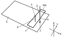
- FIG. 1 is a conceptual diagram showing an overall configuration of antenna 100 according to the present embodiment.
- the antenna 100 includes a finite ground plane 102, a first feeding point 104, a first linear line (hereinafter also referred to as a monopole antenna) 106, a second feeding point 107, and a dipole antenna 108.
- the finite ground plane 102 serves as a base on which the antenna 100 is disposed.
- the monopole antenna 106 is connected to the first feeding point 104 and is formed by the first linear line 106.
- the first feeding point 104 is arranged on the finite ground plane 102 and serves to supply a high frequency signal to the monopole antenna 106 or receive a high frequency signal excited to the monopole antenna 106.
- the dipole antenna 108 is connected to the second feeding point 107 and formed by a plurality of linear lines.
- the second feeding point 107 is disposed on the finite ground plane 102 and plays a role of supplying a high frequency signal to the dipole antenna 108 or receiving a high frequency signal excited by the dipole antenna 108.
- the monopole antenna 106 is configured on substantially the same plane as the dipole antenna 108.
- the dipole antenna 108 is formed by a second linear line 110 and a third linear line 112 connected to the second linear line 110.
- the second linear line 110 is disposed at substantially equal intervals from the monopole antenna 106 and substantially parallel to the monopole antenna 106.
- the third linear line 112 is connected to the second linear line 110 and is formed substantially at right angles to the second linear line 110.
- the monopole antenna 106 can receive vertically polarized waves, while the dipole antenna 108 can receive horizontally polarized waves.
- the antenna 100 can receive both vertically polarized waves and horizontally polarized waves by the monopole antenna 106 and the dipole antenna 108.
- a monopole antenna 106 is disposed in the space of the dipole antenna 108. Therefore, since the monopole antenna 106 and the dipole antenna 108 are formed on substantially the same plane, it is possible to reduce the size.
- FIG. 2 is a conceptual diagram showing a current flow in antenna 100 according to the embodiment of the present invention.
- a broken line 200 having a substantially elliptical partial shape schematically indicates the amplitude value of the current of the dipole antenna 108.
- a linear arrow 204 schematically indicates the direction of current flowing through the dipole antenna 108.
- the dipole antenna 108 has a maximum current value in the vicinity of the second feeding point 107. Further, the dipole antenna 108 has the minimum current amplitude value near the antenna end 206 and the antenna end 208. As shown by the straight arrow 204 in FIG. 2, the dipole antenna 108 according to the present embodiment represents a state at the time when current flows from the antenna end 206 to the antenna end 208 in the illustrated direction.
- the second linear lines 110 are set at equal intervals from the monopole antenna 106, and the direction of current flow through each of the second linear lines 110 is the reverse direction. That is, currents are excited in opposite directions to the plurality of linear lines of the second linear line 110. Therefore, on the monopole antenna 106, the magnetic fields generated by the currents flowing through the respective linear lines of the second linear line 110 work in the direction in which they cancel each other. That is, the monopole antenna 106 is arranged in a region where no magnetic field is generated by the second linear line 110.
- each antenna can receive radio waves with polarized waves orthogonal to each other. That is, the monopole antenna 106 can receive a radio wave having a polarization orthogonal to the dipole antenna 108 without being affected by the dipole antenna 108.
- the antenna 100 can receive both vertically polarized waves and horizontally polarized waves by the monopole antenna 106 and the dipole antenna 108. Further, by disposing the monopole antenna 106 in the space of the dipole antenna 108, the monopole antenna 106 and the dipole antenna 100 are formed on substantially the same plane, so that the size can be reduced. become. In addition, due to the miniaturization, even when the monopole antenna 106 and the dipole antenna 108 are close to each other, it is possible to receive radio waves without coupling (interference) with each other.
- FIG. 3 is a conceptual diagram showing an overall configuration of another example antenna 100A according to the embodiment of the present invention.
- the dipole antenna 108 ⁇ / b> A further includes a fourth linear line 300 in addition to the dipole antenna 108 shown in FIG. 1.
- the fourth linear line 300 is connected to the third linear line 112.
- the fourth linear line 300 is formed substantially at right angles to the third linear line 112.
- the fourth linear line 300 and the monopole antenna 106 are arranged at a distance of ⁇ / 4 or more.
- ⁇ indicates the wavelength of the radio wave having the maximum wavelength among the radio waves that can be received by the antenna 100.
- the monopole antenna 106 is formed on substantially the same plane as the dipole antenna 108A.
- the antenna 100A can receive a wider band radio wave by adding the fourth linear line 300, and the fourth line.
- the line 300 and the monopole antenna 106 are not coupled (interfered), and radio waves can be received.
- the antenna 100A of the present embodiment is not limited to this, It can also be formed by bending a single conducting wire.
- FIG. 4 is a conceptual diagram showing the overall configuration of another example antenna 100B according to the embodiment of the present invention.
- the monopole antenna 106A further includes a fifth pole formed substantially perpendicular to the monopole antenna (first linear line) 106.
- a linear track 400 is provided.
- the fifth linear line 400 is connected to the first linear line 106.
- the fifth linear line 400 is connected to the first feeding point 104. That is, the monopole antenna 106 ⁇ / b> A is connected to the first feeding point 104 and is formed by at least the first linear line 106.
- the antenna 100B can ensure the antenna gain in a wider frequency band than the antenna 100A shown in FIG. 3 by the fifth linear line 400. It becomes possible. That is, generally, the shorter the line length of the monopole antenna 106A, the higher frequency signal component can be received. Therefore, by increasing the line length, a signal component having a lower frequency can be received. Further, since the first feeding point 104 and the second feeding point 107 can be arranged apart from each other as compared with the antenna 100A shown in FIG. 3, interference at the feeding point can be reduced.
- the present embodiment is not limited to this, and a single conductor is used. It is also possible to configure by bending the.
- FIG. 5 is a conceptual diagram showing the overall configuration of another example antenna 100C and the configuration of the receiving apparatus according to the embodiment of the present invention.
- the monopole antenna 500 is connected to the third feeding point 502.
- the receiving apparatus includes an antenna 100C and a receiving unit 516.
- the reception unit 516 includes a demodulation unit 514, a detection unit 510, and a control unit 512.
- Demodulator 514 is connected to the feed point of monopole antenna 106A, monopole antenna 500, and dipole antenna 108A. Then, radio waves received by at least one of the monopole antenna 106A, the monopole antenna 500, and the dipole antenna 108A are demodulated.
- Detection unit 510 is connected to the feed point of monopole antenna 106A and dipole antenna 108A, respectively. The detection unit 510 detects the reception level of the radio wave received by each antenna and outputs a detection signal to the control unit 512.
- control unit 512 The output of the control unit 512 is connected to a variable mechanism unit 503 that changes the installation angle of the monopole antenna 500. Then, control unit 512 changes the installation angle of monopole antenna 106A with respect to monopole antenna 106 using the input detection signal.
- control unit 512 changes the installation angle of monopole antenna 106A with respect to monopole antenna 106 using the input detection signal.
- the detection unit 510 may be formed integrally with the control unit 512.
- the monopole antenna 106 receives vertical polarization, while the dipole antenna 108A receives horizontal polarization.
- a monopole antenna (sixth linear line) 500 that can change the angle of the monopole antenna 106 with respect to the received polarization is provided. Then, depending on the reception situation, the monopole antenna 500 can be received by the monopole antenna 500 by rotating by using the variable mechanism unit 503 under the control of the control unit 512. It will be. That is, antenna 100C according to the present embodiment is further formed on substantially the same plane as dipole antenna 108A, is connected to third feeding point 502, and can change the installation angle with respect to monopole antenna 106A. 6 linear lines 500, and the sixth linear line 500 can receive both vertically polarized waves and horizontally polarized waves.
- this configuration makes it possible to construct an optimal antenna configuration according to radio wave conditions. That is, since the antenna 100C is configured by four linear lines together with the fixed monopole antenna 106A and dipole antenna 108A described above, it is possible to receive more radio waves having a plurality of polarization planes. It is.
- the receiving device is a receiving device including antenna 100C capable of receiving radio waves, and antenna 100C includes three or more different feeding points and three or more different feeding points.
- An antenna group connected to a point and capable of receiving three or more independent polarized waves and a demodulator 514 that demodulates radio waves received by the antenna group may be provided.
- the antenna group of the receiving apparatus may be formed by at least the dipole antenna 108A, the monopole antenna 106A, and the monopole antenna 500 that can change the installation angle with respect to the monopole antenna 106A.
- the monopole antenna 500 is configured in the same plane as the fixed monopole antenna 106A and dipole antenna 108A, so that the structure of the antenna 100C itself is not three-dimensional and can be miniaturized.
- the monopole antenna 500 can be rotated substantially 360 degrees.
- the variable mechanism unit 503 may be able to continuously rotate the monopole antenna 500 like a camera platform that fixes a camera, a telescope, and the like to a mount such as a tripod.
- a stopper mechanism (not shown) may be added.
- the stopper mechanism is a mechanism that intermittently fixes the rotation angle of the monopole antenna 500, and can facilitate the setting of the rotation angle by the user.
- the present embodiment is not limited to this, and by providing the control unit 512, the angle of the monopole antenna 500 can be automatically set according to the reception situation.
- the following two angle setting methods are conceivable.
- the antenna 100C of the present embodiment receives vertical polarization by the monopole antenna 106A, and receives horizontal polarization by the dipole antenna 108A. Therefore, in the first automatic setting method, based on the signal input from the detection unit 510, the control unit 512 first receives the vertical polarization received by the fixed monopole antenna 106A and the horizontal polarization received by the dipole antenna 108A. Compare which reception level of polarization is higher.
- the control unit 512 changes the monopole antenna 500 to an angle at which horizontal polarization can be received.
- the control unit 512 changes the monopole antenna 500 to an angle at which vertical polarization can be received. That is, the monopole antenna (sixth linear line) 500 receives vertical polarization or horizontal polarization with a high reception level received by either the monopole antenna 106A or the dipole antenna 108A. The installation angle with respect to the monopole antenna 106A is changed.
- the monopole antenna 500 that can automatically change the angle can receive radio waves with a high reception level without any user effort. It is possible to increase the reception level.
- the method for automatically setting the angle of the monopole antenna 500 has been described.
- the distance between the monopole antenna 500 and the fourth linear line 300 becomes very narrow, and the monopole antenna 500 and the fourth linear line 300 are coupled. (Interference) may occur.
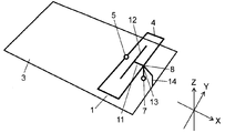
- the second automatic setting method as shown in FIG. 6, the direction (upward in the drawing) opposite to the direction (upward in the drawing) in which the first linear line 106 is arranged from the first feeding point 104 described above. ),
- the installation angle of the monopole antenna (sixth linear line) 500 with respect to the monopole antenna 106A that receives the above-described vertical polarization or horizontal polarization is changed.
- the drawings show the variable mechanism unit 503 and the receiving unit 516.
- a radio wave having a high reception level can be generated by the monopole antenna 500 capable of changing the angle in addition to the fixed monopole antenna 106A and the dipole antenna 108A while preventing mutual interference due to coupling between the antennas. It becomes possible to receive, and the reception level can be further increased.
- the configuration in which the monopole antenna 500 is formed in the same plane as the fixed monopole antenna 106A and the dipole antenna 108A has been described.
- the control unit 512 causes the monopole antenna 500 to be out of the same plane. It is also possible to set the angle to be changeable.
- the present invention can be similarly applied to a configuration in which a vertically polarized wave is received by the dipole antenna 108A and a horizontally polarized wave is received by the monopole antenna 106A.
- the receiving apparatus is a receiving apparatus including an antenna 100C capable of receiving radio waves, and the antenna 100C is connected to the first feeding point 104 and at least the first linear line.
- the receiving apparatus also includes a demodulator 514 that demodulates radio waves received by either the monopole antenna 106A or the dipole antenna 108A.
- the dipole antenna 108 ⁇ / b> A is a second line formed by a plurality of linear lines arranged substantially in parallel with the first linear line 106 at substantially equal intervals from the first linear line 106. It has the linear track
- the monopole antenna 106A is formed on substantially the same plane as the dipole antenna 108A. With such a configuration, it is possible to receive more radio waves having a plurality of polarization planes.
- the present invention can be used for a receiving apparatus that receives a broadcast wave or the like.
- the present invention can be used for a receiving apparatus having an antenna including a dipole antenna and a monopole antenna.
Abstract
アンテナは、電波を受信可能なアンテナであって、第1の給電点に接続され、第1の線状線路により形成されるモノポールアンテナと、第2の給電点に接続された複数の線状線路により形成されるダイポールアンテナとを備え、ダイポールアンテナは、第1の線状線路から実質的に等間隔で、第1の線状線路と実質的に平行に配置された複数の線状線路からなる第2の線状線路と第2の線状線路と実質的に直角に形成された第3の線状線路とからなり、第2の線状線路を形成する複数の線状線路には、互いに反対方向に電流が励起されるとともに、モノポールアンテナはダイポールアンテナと実質的に同一面上に形成される。
Description
本発明は、放送信号等の電波を受信するアンテナ及びアンテナを備えた受信装置に関する。特に、ダイポールアンテナ(Dipole Antenna)とモノポールアンテナ(Monopole Antenna)とを備えたアンテナを有する受信装置に関する。
従来、図8Aに図示するように、ダイポールアンテナとして、ケーブル800の先端に180度反対方向(左右対称)に広げられた直線状のダイポールアンテナ802を設けてアンテナを形成する構成が知られている。この構成によると、非常に簡易な構造でアンテナを形成することが可能になるという特徴がある。
一方、従来のダイポールアンテナでは、直交方向の電波を受信することができないという課題が生じる。図8Bは、図8Aに示したダイポールアンテナ802を上部から示した図である。この図8Bにおいて、ダイポールアンテナ802の指向特性804を示している。この図に示すように、ダイポールアンテナ802の水平方向に対しては指向性を有するため、水平方向の電波を受信することは可能となる。しかし、垂直方向については、指向性を有しないため、垂直方向の電波を受信することはできない。
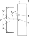
また、このような課題を解決するために、ダイポールアンテナの対称軸上にモノポールアンテナを実質的に直交する方向に近接配置する構成が知られている(例えば、特許文献1参照)。この構成では、図9に示すように、少なくともループ状線路4と給電点5から形成されるダイポールアンテナ1に対して、モノポールアンテナ2を直交する方向に近接配置することにより、水平方向及び垂直方向のいずれの方向に対しても、電波を受信することが可能になる。
但し、特許文献1の構成においては、ダイポールアンテナ(ループ状線路)1をxy平面とすると、モノポールアンテナ2はz軸方向に直交配置されていることから、3次元の構成となっている。従って、アンテナ自体を小型化することが困難になるという課題が存在する。
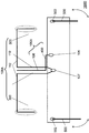
また、特許文献1の構成においては、図10に示すように、モノポールアンテナ2の構成に代えて、モノポールアンテナ2の一種である、逆Fアンテナ11を設ける構成についても記載されている。しかしながら、この場合であっても、z軸方向に少なからず距離を有するため、図9と同様に、アンテナ自体の小型化することが困難になるという課題が存在する。
本発明のアンテナは、電波を受信可能なアンテナであって、モノポールアンテナとダイポールアンテナとを備えている。モノポールアンテナは、第1の給電点に接続され、かつ少なくとも第1の線状線路により形成される。ダイポールアンテナは、第2の給電点に接続され、かつ複数の線状線路により形成される。そして、ダイポールアンテナは、第2の線状線路と第3の線状線路とを有している。第2の線状線路は、第1の線状線路から実質的に等間隔で、第1の線状線路と実質的に平行に配置された複数の線状線路を有する。第3の線状線路は、第2の線状線路に接続され、かつ第2の線状線路に対して実質的に直角に形成されている。また、ダイポールアンテナの第2の線状線路の複数の線状線路には、互いに反対方向に電流が励起される。そして、モノポールアンテナは、ダイポールアンテナと実質的に同一面上に形成される。
この構成により、本発明のアンテナは、水平偏波・垂直偏波を受信することができる。さらに、ダイポールアンテナのスペース内に、モノポールアンテナを配置している。したがって、モノポールアンテナとダイポールアンテナが実質的に同一面上に構成されていることから、小型化を行うことが可能になる。さらに、第2の線状線路を構成する複数の線状線路は、モノポールアンテナから実質的に等間隔で、互いに反対方向に電流が励起される。したがって、小型化のために、ダイポールアンテナのスペース内に、モノポールアンテナを配置しているものの、モノポールアンテナ上においては、ダイポールアンテナからの影響を受けることなく電波を受信することが可能になる。
また、本発明のアンテナのダイポールアンテナは、さらに、第3の線状線路に接続され、第3の線状線路と実質的に直角に形成された第4の線状線路を備え、第4の線状線路とモノポールアンテナは、λ/4以上の距離を有していてもよい。
本発明のアンテナは、モノポールアンテナは、さらに、第1の線状線路と実質的に直角に形成された第5の線状線路を有し、第5の線状線路が第1の給電点に接続されていてもよい。
また、本発明のアンテナは、さらに、ダイポールアンテナと実質的に同一面上に構成され、モノポールアンテナに対する設置モノポールアンテナに対する設置角度を変更可能な第6の線状線路を有し、第6の線状線路は、垂直偏波及び水平偏波のいずれも受信可能としてもよい。
また、本発明のアンテナの第6の線状線路は、モノポールアンテナ又はダイポールアンテナのいずれかにより受信されている受信レベルが高い垂直偏波又は水平偏波を受信するよう角度が変更されていてもよい。
また、本発明のアンテナの第6の線状線路は、第1の給電点から第1の線状線路が構成される方向とは反対方向において、垂直偏波又は水平偏波を受信するように角度が変更されていてもよい。
また、本発明のアンテナは、モノポールアンテナ又はダイポールアンテナの少なくともいずれか1つが樹脂封止され、固定されていてもよい。
また、本発明の受信装置は、電波を受信可能なアンテナを備えた受信装置であって、アンテナは、モノポールアンテナと、ダイポールアンテナと、を備えている。モノポールアンテナは、第1の給電点に接続され、かつ少なくとも第1の線状線路により形成される。ダイポールアンテナは、第2の給電点に接続され、かつ複数の線状線路を有する。また、受信装置は、モノポールアンテナ又はダイポールアンテナのいずれかにより受信された電波を復調する復調部を備えている。そして、ダイポールアンテナは、第2の線状線路と第3の線状線路とを有している。第2の線状線路は、第1の線状線路から実質的に等間隔で、第1の線状線路と実質的に平行に配置された複数の線状線路により形成されている。第3の線状線路は、第2の線状線路と実質的に直角に形成されている。そして、第2の線状線路を形成する複数の線状線路には、反対方向に電流が励起されている。また、モノポールアンテナは、ダイポールアンテナと実質的に同一面上に形成される。
また、本発明の受信装置は、電波を受信可能なアンテナを備えた受信装置であって、アンテナは、異なる3以上の給電点と、異なる3以上の給電点に接続された、独立した3以上の偏波を受信可能なアンテナ群と、アンテナ群により受信した電波を復調する復調部と、を備えていてもよい。
(実施の形態)
本発明の実施の形態に係るアンテナの構成について、図1から図7を参照しながら説明する。図1は、本実施の形態に係るアンテナ100の全体構成を示した概念図である。
本発明の実施の形態に係るアンテナの構成について、図1から図7を参照しながら説明する。図1は、本実施の形態に係るアンテナ100の全体構成を示した概念図である。
最初に、本実施の形態に係るアンテナ100の構成について、図1を参照しながら説明する。アンテナ100は、有限地板102と、第1の給電点104と、第1の線状線路(以下、モノポールアンテナとも称する)106と、第2の給電点107と、ダイポールアンテナ108とを備える。有限地板102は、アンテナ100を配置する土台となる。モノポールアンテナ106は、第1の給電点104に接続され、かつ第1の線状線路106により形成される。第1の給電点104は、有限地板102上に配置され、モノポールアンテナ106へ高周波数の信号を供給、またはモノポールアンテナ106に励起した高周波数の信号を受信する役割を果たす。ダイポールアンテナ108は、第2の給電点107に接続され、かつ複数の線状線路により形成される。第2の給電点107は、有限地板102上に配置され、ダイポールアンテナ108へ高周波数の信号を供給、またはダイポールアンテナ108に励起した高周波数の信号を受信する役割を果たす。また、モノポールアンテナ106は、ダイポールアンテナ108と実質的に同一面上に構成されている。
ここで、ダイポールアンテナ108の構成について、詳細に説明する。ダイポールアンテナ108は、第2の線状線路110と、第2の線状線路110と接続された第3の線状線路112とにより形成されている。第2の線状線路110は、モノポールアンテナ106から実質的に等間隔で、モノポールアンテナ106と実質的に平行に配置されている。また、第3の線状線路112は、第2の線状線路110に接続され、かつ第2の線状線路110に対して実質的に直角に形成されている。
この構成により、モノポールアンテナ106により、垂直偏波を受信し、一方、ダイポールアンテナ108により、水平偏波を受信することが可能になる。
以上のような構成により、本実施の形態に係るアンテナ100は、モノポールアンテナ106及びダイポールアンテナ108により、垂直偏波及び水平偏波のいずれの電波も受信することが可能になる。また、ダイポールアンテナ108のスペース内に、モノポールアンテナ106を配置している。したがって、モノポールアンテナ106とダイポールアンテナ108が実質的に同一面上に形成されていることから、小型化を行うことが可能になる。
次に、本実施の形態に係るアンテナ100における電流の流れについて、図2を参照しながら説明する。図2は、本発明の実施の形態に係るアンテナ100における電流の流れを示した概念図である。図2において、実質的に楕円形の一部形状のような破線200は、ダイポールアンテナ108の電流の振幅値を模式的に示している。また、直線状の矢印204は、ダイポールアンテナ108に流れる電流の方向を模式的に示している。
破線200に示すように、ダイポールアンテナ108は、第2の給電点107付近で電流値が最大となる。また、ダイポールアンテナ108は、アンテナ端206、及びアンテナ端208付近で電流の振幅値が最小となっている。なお、図2の直線状の矢印204に示すように、本実施の形態のダイポールアンテナ108において、アンテナ端206からアンテナ端208に図示する方向に電流が流れた時点の状態を表わしている。
このような状況において、モノポールアンテナ106上において、第2の線状線路110を流れる電流により生じる磁場について説明する。第2の線状線路110がモノポールアンテナ106から等間隔に設定されており、かつ第2の線状線路110のそれぞれの線状線路に電流の流れる方向が逆方向である。すなわち、第2の線状線路110の複数の線状線路には、互いに反対方向に電流が励起されている。したがって、モノポールアンテナ106上において、第2の線状線路110のそれぞれの線状線路に流れる電流により生じる磁場が、打ち消しあう方向に働く。すなわち、第2の線状線路110によって磁界が生じない領域に、モノポールアンテナ106を配置していることとなる。
このような構成により、モノポールアンテナ106及びダイポールアンテナ108が近接領域に配置されているにもかかわらず、それぞれのアンテナは、互いに直交する偏波の電波をそれぞれ受信することができる。すなわち、モノポールアンテナ106は、ダイポールアンテナ108からの影響を受けることなく、ダイポールアンテナ108に直交する偏波の電波を受信することが可能になる。
また、本実施の形態に係るアンテナ100は、モノポールアンテナ106及びダイポールアンテナ108により、垂直偏波及び水平偏波のいずれの電波も受信することが可能になる。さらに、ダイポールアンテナ108のスペース内に、モノポールアンテナ106を配置することにより、モノポールアンテナ106とダイポールアンテナ100が実質的に同一面上に形成されていることから、小型化を行うことが可能になる。また、小型化により、モノポールアンテナ106とダイポールアンテナ108が近接しているにもかかわらず、互いのアンテナが結合(干渉)することなく、電波を受信することが可能になる。
次に、本発明の実施の形態に係るアンテナ100のダイポールアンテナ108の変形例について、図面を参照しながら説明する。図3は、本発明の実施の形態に係る他の1例のアンテナ100Aの全体構成を示した概念図である。図3に示すように、ダイポールアンテナ108Aは、図1に示したダイポールアンテナ108に加えて、さらに、第4の線状線路300を備えている。第4の線状線路300は、第3の線状線路112に接続されている。また、第4の線状線路300は、第3の線状線路112とは実質的に直角に形成されている。さらに、第4の線状線路300とモノポールアンテナ106とは、λ/4以上の距離に配置されている。なお、ここで、λとはアンテナ100が受信可能な電波のうち、最大波長を有する電波の波長を示している。また、図3に示すように、モノポールアンテナ106は、ダイポールアンテナ108Aと実質的に同一面上に形成されている。
以上のような構成により、本発明の実施の形態に係るアンテナ100Aは、第4の線状線路300を加えたことにより、より広帯域な電波を受信することが可能になるとともに、第4の線状線路300とモノポールアンテナ106とが結合(干渉)することがなく、電波を受信することが可能になる。
なお、上述した説明においては、第3の線状線路112に第4の線状線路300を接続する構成について説明したが、本実施の形態のアンテナ100Aは、これに限定されるものではなく、一本の導線を折り曲げることにより、形成することも可能である。
次に、本発明の実施の形態に係るアンテナ100のモノポールアンテナ106の変形例について、図面を参照しながら説明する。図4は、本発明の実施の形態に係る他の1例のアンテナ100Bの全体構成を示した概念図である。図4に示すように、モノポールアンテナ106Aは、図3に示したアンテナ100Aに加えて、さらに、モノポールアンテナ(第1の線状線路)106と実質的に直角に形成された第5の線状線路400を備えている。第5の線状線路400は、第1の線状線路106に接続されている。そして、第5の線状線路400は、第1の給電点104に接続されている。すなわち、モノポールアンテナ106Aは、第1の給電点104に接続され、かつ少なくとも第1の線状線路106により形成される。
以上のような構成により、本実施の形態に係るアンテナ100Bは、この第5の線状線路400により、図3に示したアンテナ100Aに比べて、より広い周波数帯域でアンテナ利得を確保することが可能になる。つまり、一般的には、モノポールアンテナ106Aの線路長が短いほど、より高周波数の信号成分を受信することができる。したがって、この線路長を長くすることにより、より低周波数の信号成分を受信することができる。また、図3に示したアンテナ100Aに比べて、第1の給電点104と第2の給電点107とを互いに離して配置できるため、給電点における干渉を低減できる。
なお、上述した説明において、第1の線状線路106に第5の線状線路400を接続する構成について説明したが、本実施の形態は、これに限定されるものではなく、一本の導線を折り曲げることにより、構成することも可能である。
上述した実施の形態においては、アンテナ100、100A、100Bの構成として、固定したモノポールアンテナ106、106A及びダイポールアンテナ108,108Aの構成について説明した。以下では、図5に示すように、角度を可変可能なモノポールアンテナ(第6の線状線路)500をさらに備えたアンテナ100Cについて説明する。図5は、本発明の実施の形態に係る他の1例のアンテナ100Cの全体構成と受信装置の構成とを示した概念図である。なお、モノポールアンテナ500は、第3の給電点502に接続されている。
受信装置は、アンテナ100Cと受信部516とを有する。受信部516は、復調部514と検出部510と制御部512とを有する。復調部514は、モノポールアンテナ106A、モノポールアンテナ500、及びダイポールアンテナ108Aの給電点にそれぞれ接続されている。そして、モノポールアンテナ106A、モノポールアンテナ500、又はダイポールアンテナ108Aの少なくともいずれか1つにより受信された電波を復調する。検出部510は、モノポールアンテナ106A、及びダイポールアンテナ108Aの給電点にそれぞれ接続されている。検出部510は、それぞれのアンテナで受信した電波の受信レベルを検出し、制御部512に検出信号を出力する。制御部512の出力は、モノポールアンテナ500の設置角度を変更する可変機構部503に接続されている。そして、制御部512は、入力した検出信号を用いて、モノポールアンテナ106Aにおけるモノポールアンテナ106に対する設置角度を変更する。なお、検出部510は、制御部512に組み込まれて一体化して形成されていてもよい。
上述したように、本実施の形態のアンテナ100Cでは、モノポールアンテナ106により、垂直偏波を受信し、一方、ダイポールアンテナ108Aにより、水平偏波を受信している。これに加えて、モノポールアンテナ106の受信偏波に対する角度を可変可能なモノポールアンテナ(第6の線状線路)500を設けている。そして、受信状況に応じて、モノポールアンテナ500を制御部512の制御により、可変機構部503を用いて回転させることにより、モノポールアンテナ500により、垂直偏波及び水平偏波のいずれも受信可能になるものである。すなわち、本実施の形態にかかるアンテナ100Cは、さらに、ダイポールアンテナ108Aと実質的に同一面上に形成され、第3の給電点502に接続され、モノポールアンテナ106Aに対する設置角度を変更可能な第6の線状線路500を有し、第6の線状線路500は、垂直偏波、水平偏波のいずれも受信可能である。
つまり、屋内での受信時のように、垂直偏波と水平偏波が混在する場合であっても、この構成により、電波状況に応じて最適なアンテナ構成を構築することが可能になる。すなわち、上述した固定したモノポールアンテナ106A及びダイポールアンテナ108Aと合わせて4本の線状線路によりアンテナ100Cが構成されるため、複数偏波面を有するより多くの電波を受信することが可能になるものである。
すなわち、上記したように、本実施の形態にかかる受信装置は、電波を受信可能なアンテナ100Cを備えた受信装置であって、アンテナ100Cは、異なる3以上の給電点と、異なる3以上の給電点に接続された、独立した3以上の偏波を受信可能なアンテナ群と、アンテナ群により受信した電波を復調する復調部514と、を備えてもよい。
また、本実施の形態にかかる受信装置のアンテナ群は、少なくとも、ダイポールアンテナ108A、モノポールアンテナ106A及びモノポールアンテナ106Aに対する設置角度を可変可能なモノポールアンテナ500により形成されていてもよい。
さらに、モノポールアンテナ500は、固定したモノポールアンテナ106A及びダイポールアンテナ108Aと同一平面状に構成することにより、アンテナ100C自体の構造が3次元とならず、小型化することが可能になる。
なお、モノポールアンテナ500は、実質的に360度回転させることが可能である。また、可変機構部503は、カメラや望遠鏡などと三脚などの架台とを固定する雲台のように連続的にモノポールアンテナ500を回転できてもよい。また、さらに、ストッパー機構部(図示せず)を追加してもよい。ストッパー機構部は、モノポールアンテナ500の回転角度を断続的に固定する機構であって、ユーザーによる回転角度の設定を容易にすることができる。
上述したように、モノポールアンテナ500は、ユーザーが手動により回転させる構成について説明した。しかし、本実施の形態は、これに限定されるものではなく、制御部512を設けることにより、受信状況に応じて、自動的にモノポールアンテナ500の角度を設定することも可能である。自動的にモノポールアンテナ500の角度を設定する場合には、以下のような2つの角度の設定方法が考えられる。
上述したように、本実施の形態のアンテナ100Cは、モノポールアンテナ106Aにより、垂直偏波を受信し、一方、ダイポールアンテナ108Aにより、水平偏波を受信している。そこで、第1の自動設定方法では、制御部512は、検出部510から入力された信号に基づいて、最初に、固定のモノポールアンテナ106Aの受信する垂直偏波とダイポールアンテナ108Aが受信する水平偏波のいずれの受信レベルが大きいかを比較する。
次に、例えば、水平偏波の受信レベルが垂直偏波の受信レベルよりも大きい場合には、制御部512は、モノポールアンテナ500を、水平偏波を受信可能な角度に変更する。一方、例えば、垂直偏波の受信レベルが水平偏波の受信レベルよりも大きい場合には、制御部512は、モノポールアンテナ500を、垂直偏波を受信可能な角度に変更する。すなわち、モノポールアンテナ(第6の線状線路)500は、モノポールアンテナ106A、又はダイポールアンテナ108Aのいずれかにより受信されている受信レベルが高い垂直偏波、又は水平偏波を受信するように、モノポールアンテナ106Aに対する設置角度が変更される。
以上のような構成により、固定のモノポールアンテナ106A及びダイポールアンテナ108Aに加えて、自動的に角度を可変可能なモノポールアンテナ500により、ユーザーの手間をかけることなく、受信レベルの高い電波を受信することが可能になり、より受信レベルを高めることができるものである。
上述した第1の自動設定方法においては、モノポールアンテナ500の角度を自動的に設定する方法について説明した。しかしながら、この場合、例えば、図5に示すように、モノポールアンテナ500が第4の線状線路300との距離が非常に狭くなり、モノポールアンテナ500と第4の線状線路300とが結合(干渉)してしまう場合が生じる。
そこで、第2の自動設定方法においては、図6に示すように、上述した第1の給電点104から第1の線状線路106が配置される方向(図面上方)とは反対方向(図面下方)において、モノポールアンテナ(第6の線状線路)500は、上述した垂直偏波又は水平偏波を受信するモノポールアンテナ106Aに対する設置角度を変更している。なお、図面は簡略化のため、可変機構部503や受信部516を除いて示している。
以上のような構成により、アンテナ間の結合による相互干渉を防止しつつ、固定のモノポールアンテナ106A及びダイポールアンテナ108Aに加えて、角度を可変可能なモノポールアンテナ500により、受信レベルの高い電波を受信することが可能になり、より受信レベルを高めることができるものである。
なお、上述した実施の形態においては、小型化を目的として、モノポールアンテナ500は、固定のモノポールアンテナ106A及びダイポールアンテナ108Aと同一平面状に形成されている構成について説明した。しかし、例えば、固定のモノポールアンテナ106A及びダイポールアンテナ108A及びモノポールアンテナ500のいずれの構成においても電波を受信することができない場合にのみ、制御部512により、同一平面外にモノポールアンテナ500の角度を変更可能にするという設定にすることも可能である。
なお、上述した構成では、ダイポールアンテナ108Aで水平偏波を受信し、モノポールアンテナ106Aで垂直偏波を受信する構成例について説明した。しかし、ダイポールアンテナ108Aで垂直偏波を受信し、モノポールアンテナ106Aで水平偏波を受信する構成においても同様に実施可能である。
なお、上述した構成では、ダイポールアンテナ108Aとモノポールアンテナ106Aを空中配置した例について説明した。しかし、図7に示すように、強度確保のため、例えばアクリル板700等に、モノポールアンテナ106A又はダイポールアンテナ108Aの少なくともいずれか1つを埋め込み、樹脂封止して固定した構造においても同様に本実施の形態を実施可能である。
なお、本実施の形態は、上述したように、アンテナ100Cから受信した電波を復調する復調部514を備えた受信装置に適用することが可能である。すなわち、本実施の形態にかかる受信装置は、電波を受信可能なアンテナ100Cを備えた受信装置であって、アンテナ100Cは、第1の給電点104に接続され、かつ少なくとも第1の線状線路106により形成されるモノポールアンテナ106Aと、第2の給電点107に接続された複数の線状線路を有するダイポールアンテナ108Aと、を備えている。また、受信装置は、モノポールアンテナ106A、又はダイポールアンテナ108Aのいずれかにより受信された電波を復調する復調部514を備えている。そして、ダイポールアンテナ108Aは、第1の線状線路106から実質的に等間隔で、第1の線状線路106と実質的に平行に配置された複数の線状線路により形成された第2の線状線路110と、第2の線状線路110と実質的に直角に形成された第3の線状線路112とを有している。そして、第2の線状線路110を形成する複数の線状線路には、反対方向に電流が励起される。また、モノポールアンテナ106Aは、ダイポールアンテナ108Aと実質的に同一面上に形成される。このような構成により、複数偏波面を有するより多くの電波を受信することが可能になるものである。
本発明は、放送波等を受信する受信装置に利用可能である。特に、ダイポールアンテナとモノポールアンテナとを備えたアンテナを有する受信装置に利用可能である。
100 アンテナ
100A アンテナ
100B アンテナ
100C アンテナ
102 有限地板
104 第1の給電点
106 モノポールアンテナ(第1の線状線路)
106A モノポールアンテナ
107 第2の給電点
108 ダイポールアンテナ
108A ダイポールアンテナ
108B ダイポールアンテナ
110 第2の線状線路
112 第3の線状線路
200 破線
204 矢印
206 アンテナ端
208 アンテナ端
300 第4の線状線路
400 第5の線状線路
500 モノポールアンテナ(第6の線状線路)
502 第3の給電点
503 可変機構部
510 検出部
512 制御部
514 復調部
516 受信部
700 アクリル板
Claims (10)
- 電波を受信可能なアンテナであって、
第1の給電点に接続され、かつ少なくとも第1の線状線路により形成されるモノポールアンテナと、
第2の給電点に接続され、かつ複数の線状線路により形成されるダイポールアンテナと、を備え、
前記ダイポールアンテナは、
前記第1の線状線路から実質的に等間隔で、前記第1の線状線路と実質的に平行に配置された複数の線状線路を有する第2の線状線路と、
前記第2の線状線路に接続され、かつ第2の線状線路に対して実質的に直角に形成された第3の線状線路と、を有し、
前記第2の線状線路の複数の前記線状線路には、互いに反対方向に電流が励起され、
前記モノポールアンテナは、
前記ダイポールアンテナと実質的に同一面上に形成されるアンテナ。 - 前記ダイポールアンテナは、さらに、前記第3の線状線路に接続され、
前記第3の線状線路と実質的に直角に形成された第4の線状線路を備え、
前記第4の線状線路と前記モノポールアンテナとは、λ/4以上の距離を有する請求項1記載のアンテナ。 - 前記モノポールアンテナは、さらに、第1の線状線路と実質的に直角に形成された第5の線状線路を有し、
前記第5の線状線路が、前記第1の給電点に接続されている請求項1記載のアンテナ。 - 前記アンテナは、さらに、前記ダイポールアンテナと実質的に同一面上に形成され、第3の給電点に接続され、前記モノポールアンテナに対する設置角度を変更可能な第6の線状線路を有し、
前記第6の線状線路は、垂直偏波、水平偏波のいずれも受信可能である請求項1記載のアンテナ。 - 前記第6の線状線路は、前記モノポールアンテナ又は前記ダイポールアンテナのいずれかにより受信されている受信レベルが高い垂直偏波又は水平偏波を受信するように前記モノポールアンテナに対する設置角度が変更される請求項4記載のアンテナ。
- 前記第6の線状線路は、前記第1の給電点から前記第1の線状線路が形成される方向とは反対方向において、垂直偏波又は水平偏波を受信するように前記モノポールアンテナに対する設置角度を変更している請求項4記載のアンテナ。
- 前記アンテナは、さらに、前記モノポールアンテナ又は前記ダイポールアンテナの少なくともいずれか1つが樹脂封止され、固定されている請求項1記載のアンテナ。
- 電波を受信可能なアンテナを備えた受信装置であって、
前記アンテナは、
第1の給電点に接続され、かつ少なくとも第1の線状線路により形成されるモノポールアンテナと、
第2の給電点に接続され、かつ複数の線状線路を有するダイポールアンテナと、を備え、
前記受信装置は、前記モノポールアンテナ又は前記ダイポールアンテナの少なくともいずれか1つにより受信された電波を復調する復調部を備え、
前記ダイポールアンテナは、
前記第1の線状線路から実質的に等間隔で、前記第1の線状線路と実質的に平行に配置された複数の線状線路により形成された第2の線状線路と
前記第2の線状線路と実質的に直角に形成された第3の線状線路とを有し、
前記第2の線状線路を形成する複数の線状線路には、反対方向に電流が励起され、
前記モノポールアンテナは、
前記ダイポールアンテナと実質的に同一面上に形成される受信装置。 - 電波を受信可能なアンテナを備えた受信装置であって、
前記アンテナは、
異なる3以上の給電点と、
前記異なる3以上の給電点に接続された、独立した3以上の偏波を受信可能なアンテナ群と、
前記アンテナ群により受信した電波を復調する復調部と、を備えた受信装置。 - 前記アンテナ群は、少なくとも、ダイポールアンテナ、モノポールアンテナ及び前記モノポールアンテナに対する設置角度を可変可能なモノポールアンテナにより形成されている請求項9記載の受信装置。
Priority Applications (3)
| Application Number | Priority Date | Filing Date | Title |
|---|---|---|---|
| EP10735642A EP2385584A1 (en) | 2009-02-02 | 2010-01-28 | Antenna and reception apparatus provided with antenna |
| JP2010548421A JPWO2010087170A1 (ja) | 2009-02-02 | 2010-01-28 | アンテナ及びアンテナを備えた受信装置 |
| US13/146,328 US20110287731A1 (en) | 2009-02-02 | 2010-01-28 | Antenna and reception apparatus provided with antenna |
Applications Claiming Priority (2)
| Application Number | Priority Date | Filing Date | Title |
|---|---|---|---|
| JP2009-021166 | 2009-02-02 | ||
| JP2009021166 | 2009-02-02 |
Publications (1)
| Publication Number | Publication Date |
|---|---|
| WO2010087170A1 true WO2010087170A1 (ja) | 2010-08-05 |
Family
ID=42395434
Family Applications (1)
| Application Number | Title | Priority Date | Filing Date |
|---|---|---|---|
| PCT/JP2010/000477 WO2010087170A1 (ja) | 2009-02-02 | 2010-01-28 | アンテナ及びアンテナを備えた受信装置 |
Country Status (4)
| Country | Link |
|---|---|
| US (1) | US20110287731A1 (ja) |
| EP (1) | EP2385584A1 (ja) |
| JP (1) | JPWO2010087170A1 (ja) |
| WO (1) | WO2010087170A1 (ja) |
Cited By (4)
| Publication number | Priority date | Publication date | Assignee | Title |
|---|---|---|---|---|
| JP2012049852A (ja) * | 2010-08-27 | 2012-03-08 | Mitsubishi Electric Corp | アンテナ装置 |
| WO2012142196A2 (en) * | 2011-04-13 | 2012-10-18 | George Wallner | Beam forming antenna |
| JP2012209712A (ja) * | 2011-03-29 | 2012-10-25 | Toshiba Corp | アンテナ装置、無線装置 |
| CN111525229A (zh) * | 2019-02-01 | 2020-08-11 | 上海诺基亚贝尔股份有限公司 | 用于形成偶极天线阵列的支撑构件以及偶极天线阵列 |
Families Citing this family (8)
| Publication number | Priority date | Publication date | Assignee | Title |
|---|---|---|---|---|
| JP5979356B2 (ja) * | 2012-06-14 | 2016-08-24 | Tdk株式会社 | アンテナ装置 |
| CN105075006B (zh) * | 2013-03-15 | 2018-08-03 | Lg电子株式会社 | 天线模块以及包括该天线模块的移动终端 |
| GB2529884B (en) | 2014-09-05 | 2017-09-13 | Smart Antenna Tech Ltd | Reconfigurable multi-band antenna with independent control |
| US10535921B2 (en) * | 2014-09-05 | 2020-01-14 | Smart Antenna Technologies Ltd. | Reconfigurable multi-band antenna with four to ten ports |
| GB201505910D0 (en) | 2015-04-07 | 2015-05-20 | Smart Antenna Technologies Ltd | Reconfigurable 4-port multi-band multi-function antenna with a grounded dipole antenna component |
| US10084241B1 (en) * | 2018-02-23 | 2018-09-25 | Qualcomm Incorporated | Dual-polarization antenna system |
| US11024981B2 (en) * | 2018-04-13 | 2021-06-01 | Mediatek Inc. | Multi-band endfire antennas and arrays |
| RU2698078C1 (ru) * | 2018-09-20 | 2019-08-21 | Федеральное государственное бюджетное образовательное учреждение высшего образования "Воронежский государственный технический университет" | Антенная система MIMO |
Citations (5)
| Publication number | Priority date | Publication date | Assignee | Title |
|---|---|---|---|---|
| JP2001251117A (ja) * | 2000-03-02 | 2001-09-14 | Mitsubishi Electric Corp | アンテナ装置 |
| JP2002544692A (ja) * | 1999-05-06 | 2002-12-24 | カトライン−ベルケ・カーゲー | 多重帯域アンテナ |
| JP2005020301A (ja) * | 2003-06-25 | 2005-01-20 | Maspro Denkoh Corp | 2偏波共用アンテナ |
| JP2005347958A (ja) | 2004-06-01 | 2005-12-15 | Toshiba Corp | アンテナ装置 |
| JP3129971U (ja) * | 2006-05-30 | 2007-03-08 | クアンタ マイクロシステムズ インコーポレイテッド | アンテナモジュールおよび該アンテナモジュールを使った無線通信装置 |
Family Cites Families (2)
| Publication number | Priority date | Publication date | Assignee | Title |
|---|---|---|---|---|
| US7706768B2 (en) * | 2006-08-02 | 2010-04-27 | Intel Corporation | Diversity switching |
| US8064861B2 (en) * | 2008-04-14 | 2011-11-22 | Silicon Laboratories Inc. | Circuit and method for antenna selection in an antenna diversity receiver |
-
2010
- 2010-01-28 JP JP2010548421A patent/JPWO2010087170A1/ja active Pending
- 2010-01-28 US US13/146,328 patent/US20110287731A1/en not_active Abandoned
- 2010-01-28 EP EP10735642A patent/EP2385584A1/en not_active Withdrawn
- 2010-01-28 WO PCT/JP2010/000477 patent/WO2010087170A1/ja active Application Filing
Patent Citations (5)
| Publication number | Priority date | Publication date | Assignee | Title |
|---|---|---|---|---|
| JP2002544692A (ja) * | 1999-05-06 | 2002-12-24 | カトライン−ベルケ・カーゲー | 多重帯域アンテナ |
| JP2001251117A (ja) * | 2000-03-02 | 2001-09-14 | Mitsubishi Electric Corp | アンテナ装置 |
| JP2005020301A (ja) * | 2003-06-25 | 2005-01-20 | Maspro Denkoh Corp | 2偏波共用アンテナ |
| JP2005347958A (ja) | 2004-06-01 | 2005-12-15 | Toshiba Corp | アンテナ装置 |
| JP3129971U (ja) * | 2006-05-30 | 2007-03-08 | クアンタ マイクロシステムズ インコーポレイテッド | アンテナモジュールおよび該アンテナモジュールを使った無線通信装置 |
Cited By (5)
| Publication number | Priority date | Publication date | Assignee | Title |
|---|---|---|---|---|
| JP2012049852A (ja) * | 2010-08-27 | 2012-03-08 | Mitsubishi Electric Corp | アンテナ装置 |
| JP2012209712A (ja) * | 2011-03-29 | 2012-10-25 | Toshiba Corp | アンテナ装置、無線装置 |
| WO2012142196A2 (en) * | 2011-04-13 | 2012-10-18 | George Wallner | Beam forming antenna |
| WO2012142196A3 (en) * | 2011-04-13 | 2012-12-27 | George Wallner | Beam forming antenna |
| CN111525229A (zh) * | 2019-02-01 | 2020-08-11 | 上海诺基亚贝尔股份有限公司 | 用于形成偶极天线阵列的支撑构件以及偶极天线阵列 |
Also Published As
| Publication number | Publication date |
|---|---|
| EP2385584A1 (en) | 2011-11-09 |
| US20110287731A1 (en) | 2011-11-24 |
| JPWO2010087170A1 (ja) | 2012-08-02 |
Similar Documents
| Publication | Publication Date | Title |
|---|---|---|
| WO2010087170A1 (ja) | アンテナ及びアンテナを備えた受信装置 | |
| JP6013630B2 (ja) | 無指向性円偏波アンテナ | |
| CN102906936B (zh) | 用于射频应用的对称带状线平衡-不平衡变换器 | |
| JP2008098993A (ja) | アンテナ装置 | |
| US20090237319A1 (en) | Composite antenna and portable terminal using same | |
| JP2002237711A (ja) | アンテナ装置、および通信システム | |
| WO2020087390A1 (zh) | 螺旋天线及通信设备 | |
| JP2007074098A (ja) | アンテナ装置 | |
| JP2007142666A (ja) | 平面アンテナ装置 | |
| JP2009044207A (ja) | 広帯域アンテナ | |
| JP2008278414A (ja) | アンテナ装置 | |
| US10014592B2 (en) | Antenna | |
| CN105024137A (zh) | 多频通信天线装置及带该多频通信天线装置的gnss接收机 | |
| US20190363420A1 (en) | Antenna device and receiver | |
| JP4589821B2 (ja) | アンテナ装置 | |
| JP6330259B2 (ja) | 無線通信モジュール | |
| JP2010239495A (ja) | アンテナ装置 | |
| JP2008042894A (ja) | 円偏波アンテナ | |
| JP2003258546A (ja) | アンテナ、受信方法、および送信方法 | |
| JP2009017008A (ja) | アンテナ装置 | |
| US20190348739A1 (en) | Antenna device and reception device | |
| JP2005260917A (ja) | 複合アンテナ | |
| KR102471708B1 (ko) | 평판형 발룬에 의하여 급전되는 다이폴 안테나 | |
| JP2012029142A (ja) | アンテナ装置 | |
| CN209747731U (zh) | 一种天线组件 |
Legal Events
| Date | Code | Title | Description |
|---|---|---|---|
| 121 | Ep: the epo has been informed by wipo that ep was designated in this application |
Ref document number: 10735642 Country of ref document: EP Kind code of ref document: A1 |
|
| WWE | Wipo information: entry into national phase |
Ref document number: 2010548421 Country of ref document: JP |
|
| WWE | Wipo information: entry into national phase |
Ref document number: 13146328 Country of ref document: US |
|
| NENP | Non-entry into the national phase |
Ref country code: DE |
|
| WWE | Wipo information: entry into national phase |
Ref document number: 2010735642 Country of ref document: EP |