WO2010084647A1 - 光拡散フィルム及びそれを備えた装置 - Google Patents
光拡散フィルム及びそれを備えた装置 Download PDFInfo
- Publication number
- WO2010084647A1 WO2010084647A1 PCT/JP2009/067390 JP2009067390W WO2010084647A1 WO 2010084647 A1 WO2010084647 A1 WO 2010084647A1 JP 2009067390 W JP2009067390 W JP 2009067390W WO 2010084647 A1 WO2010084647 A1 WO 2010084647A1
- Authority
- WO
- WIPO (PCT)
- Prior art keywords
- light
- resin
- light diffusion
- dispersed phase
- film
- Prior art date
- Legal status (The legal status is an assumption and is not a legal conclusion. Google has not performed a legal analysis and makes no representation as to the accuracy of the status listed.)
- Ceased
Links
Images


Classifications
-
- G—PHYSICS
- G02—OPTICS
- G02B—OPTICAL ELEMENTS, SYSTEMS OR APPARATUS
- G02B5/00—Optical elements other than lenses
- G02B5/02—Diffusing elements; Afocal elements
-
- G—PHYSICS
- G02—OPTICS
- G02F—OPTICAL DEVICES OR ARRANGEMENTS FOR THE CONTROL OF LIGHT BY MODIFICATION OF THE OPTICAL PROPERTIES OF THE MEDIA OF THE ELEMENTS INVOLVED THEREIN; NON-LINEAR OPTICS; FREQUENCY-CHANGING OF LIGHT; OPTICAL LOGIC ELEMENTS; OPTICAL ANALOGUE/DIGITAL CONVERTERS
- G02F1/00—Devices or arrangements for the control of the intensity, colour, phase, polarisation or direction of light arriving from an independent light source, e.g. switching, gating or modulating; Non-linear optics
- G02F1/01—Devices or arrangements for the control of the intensity, colour, phase, polarisation or direction of light arriving from an independent light source, e.g. switching, gating or modulating; Non-linear optics for the control of the intensity, phase, polarisation or colour
- G02F1/13—Devices or arrangements for the control of the intensity, colour, phase, polarisation or direction of light arriving from an independent light source, e.g. switching, gating or modulating; Non-linear optics for the control of the intensity, phase, polarisation or colour based on liquid crystals, e.g. single liquid crystal display cells
- G02F1/133—Constructional arrangements; Operation of liquid crystal cells; Circuit arrangements
- G02F1/1333—Constructional arrangements; Manufacturing methods
- G02F1/1335—Structural association of cells with optical devices, e.g. polarisers or reflectors
- G02F1/1336—Illuminating devices
- G02F1/133602—Direct backlight
- G02F1/133606—Direct backlight including a specially adapted diffusing, scattering or light controlling members
Definitions
- the present invention relates to a light diffusion film that diffuses transmitted light isotropically or anisotropically, and a surface light source device and a display device (liquid crystal display device, etc.) provided with the light diffusion film.
- a surface light source unit (or backlight unit) is disposed on the back surface of the display panel.
- a diffusion sheet, a prism sheet, a brightness enhancement sheet (a reflective polarizing plate, etc.) and the like are used.
- a polarizing plate, a retardation plate, a color filter, and the like are also used as constituent members of a liquid crystal cell.
- planar display device flat display device
- planar display unit such as a transmissive liquid crystal display unit
- surface light source unit for illuminating the unit from the back side
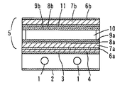
- the surface light source unit has one or a plurality of fluorescent discharge tubes (cold cathode tubes) 1, and a reflection plate 2 for reflecting light is disposed on the back side of the fluorescent discharge tube 1.
- a diffusion plate 3 for diffusing light to uniformly illuminate the display unit 5, and a prism sheet 4 is laminated on the display unit side of the diffusion plate 3.
- the surface display unit 5 includes a first polarizing film 6a, a first glass substrate 7a, a first electrode 8a formed on the glass substrate, and a first layer laminated on the electrode.
- the alignment film 9a, the liquid crystal layer 10, the second alignment film 9b, the second electrode 8b, the color filter 11, the second glass substrate 7b, and the second polarizing film 6b are sequentially stacked.
- the display unit can be directly illuminated from the back by a built-in fluorescent discharge tube (cold cathode tube) 1.
- the backlight system using such a rod-shaped (tubular) light source (lamp) has become very heavy in liquid crystal display devices with the recent increase in size of liquid crystal televisions.
- a surface light source device there is a tendency that the brightness of the light source is increased and the device is thinned.
- a lamp image in the shape of a lamp that is a light source. The resulting image and the image in which the presence of the lamp can be easily understood) are more likely to remain.
- the luminance distribution in the axial direction of the rod-shaped light source is different from that in the direction perpendicular to the axial direction, and it is difficult to uniformly illuminate the display unit, so it is difficult to expand the viewing angle. .
- an anisotropic light diffusion sheet having optically anisotropic scattering characteristics is used as the diffusion sheet, and the luminance is made uniform by utilizing the anisotropic scattering characteristics.
- anisotropic scattering is possible even when using light sources having different luminance distributions in the long axis direction and the short axis direction.
- a method is known that can make the luminance of transmitted light uniform by utilizing the characteristics. However, even if a light diffusing sheet having such anisotropic scattering characteristics is used, the erasure of the lamp image is not sufficient.
- a polycarbonate resin is known as a resin having high heat resistance and transparency.
- the polycarbonate resin has low melt fluidity, it is difficult to industrially efficiently produce a light diffusion film by a melt molding method such as melt extrusion molding.
- the polycarbonate resin does not have a high affinity with the components of the dispersed phase, voids are easily generated at the interface with the dispersed phase, and it is difficult to form the dispersed phase uniformly.
- Patent Document 1 Japanese Patent No. 4115113 (Patent Document 1) as a light diffusion sheet used for a backlight system displays a tubular light source and light from the tubular light source incident from the side and emitted from a flat emission surface.
- a surface light source unit comprising a film, wherein the anisotropic light scattering film is composed of a laminated film in which transparent resin layers are laminated on both sides of an anisotropic light scattering layer, and the anisotropic light scattering layer is composed of a resin.
- a dispersed phase composed of a resin having an average aspect ratio of 5 to 1000 dispersed in the continuous phase and having a refractive index different from that of the resin of the continuous phase.
- a combination of a propylene resin and a styrene resin, or a combination of a propylene resin and a polycarbonate resin, and the transparent resin layer is the same resin as the continuous phase, and has a glass transition temperature or a melting point.
- a surface light source unit comprising a transparent resin having a temperature of 130 to 280 ° C. and having a plurality of anisotropic light scattering films disposed between the light guide member and the display unit with different light scattering directions. It is disclosed.
- an object of the present invention is to reduce light leakage even at a high transmittance, and to reduce the thickness and increase the brightness of a surface light source device such as a backlight type liquid crystal display device without developing a lamp image (lamp image).
- An object of the present invention is to provide a light diffusing film that can be formed and a device (a display device such as a surface light source device or a liquid crystal display device) including the same.
- Another object of the present invention is to provide a light diffusing film capable of suppressing changes in light diffusing characteristics even when used at high temperatures and a device (display device such as a surface light source device or a liquid crystal display device) provided with the same. It is in.
- Still another object of the present invention is to provide a light diffusing film that can easily form a film having a uniform dispersed phase even when a polycarbonate-based resin having low fluidity and low affinity for a transparent resin is used, and an apparatus (surface) having the same. It is to provide a light source device or a display device such as a liquid crystal display device.
- Another object of the present invention is to provide a light diffusing film and a liquid crystal display device including the same, which can cope with the thinning of the device even if it is a large liquid crystal display device and can be easily manufactured.
- the present inventors have made a transparent resin having a matrix phase (continuous phase) made of a polycarbonate-based resin and a dispersed phase having a predetermined refractive index difference with respect to the polycarbonate-based resin.
- a transparent resin having a matrix phase (continuous phase) made of a polycarbonate-based resin and a dispersed phase having a predetermined refractive index difference with respect to the polycarbonate-based resin.
- the light diffusing film of the present invention comprises a continuous phase composed of a polycarbonate resin, a resin dispersed in the continuous phase, and an absolute value of a difference in refractive index from the polycarbonate resin of 0.045 to 0.085.
- a light diffusion layer formed of a dispersed phase composed of The continuous phase may be composed of a polycarbonate resin having a viscosity average molecular weight of 15000 to 25000, and the melt flow rate (MFR) of the polycarbonate resin is 5 under the conditions of 300 ° C. and 1.2 kg load in accordance with ISO 1133. it may be about ⁇ 30cm 3/10 minutes.
- the light diffusion film of the present invention may include a particulate dispersed phase in which the dispersed phase has an average aspect ratio greater than 1 and the major axis direction is oriented in a certain direction of the film.
- the average length of the minor axis of the particulate dispersed phase is about 0.01 to 10 ⁇ m, and the average aspect ratio of the particulate dispersed phase is about 3 to 100.
- the light diffusion film of the present invention may include a transparent layer laminated on at least one surface of the light diffusion layer.
- the transparent layer may be a resin layer including at least one selected from an ultraviolet absorber and a light stabilizer.
- the light diffusion layer may have a thickness of about 3 to 500 ⁇ m, and the total light transmittance of the film may be 60% or more.
- the present invention includes a surface light source device and a display device (such as a liquid crystal display device) provided with the light diffusion film.
- film is used to mean including a sheet regardless of thickness.
- the matrix phase (continuous phase) is composed of a polycarbonate-based resin and the dispersed phase is composed of a resin having a specific refractive index difference, light leakage can be suppressed even with high transmittance, and the lamp A surface light source device such as a backlight type liquid crystal display device can be made thinner and higher in brightness without developing an image (lamp image).
- a surface light source device such as a backlight type liquid crystal display device can be made thinner and higher in brightness without developing an image (lamp image).
- it has high heat resistance and can suppress changes in light diffusion characteristics over a long period of time even when used at high temperatures.
- a polycarbonate resin having low fluidity and low affinity for a transparent resin is used, a film having a uniform dispersed phase can be easily formed.
- even a large-sized liquid crystal display device can cope with the thinning of the device and can be easily manufactured.
- FIG. 1 is a schematic sectional view showing a surface light source device and a transmissive liquid crystal display device.
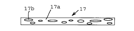
- FIG. 2 is a schematic cross-sectional view showing an example of a light diffusion film.
- FIG. 3 is a schematic sectional view showing another example of the light diffusion film.
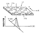
- FIG. 4 is a conceptual diagram for explaining anisotropic scattering of the light diffusion film.
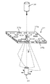
- FIG. 5 is a schematic diagram for explaining a method of measuring light scattering characteristics.
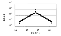
- FIG. 6 is a graph of the scattered light intensity with respect to the scattering angle in a light diffusion film with light leakage.
- FIG. 7 is a graph of the scattered light intensity with respect to the scattering angle in a light diffusion film having no light omission.
- the light diffusion film of the present invention includes a light diffusion layer composed of a continuous phase and a dispersed phase.
- the continuous phase is composed of a polycarbonate-based resin from the viewpoint of achieving both excellent optical properties and high heat resistance.
- the polycarbonate-based resin includes aromatic polycarbonate based on bisphenols.
- bisphenols include biphenols such as dihydroxybiphenyl, 2,2-bis (4-hydroxyphenyl) propane (bisphenol A), bis (4-hydroxyphenyl) methane (bisphenol F), 1,1-bis ( Bis (hydroxyphenyl) alkanes such as 4-hydroxyphenyl) ethane (bisphenol AD), bis (hydroxyaryl) alkanes such as bis (4-hydroxytolyl) alkane, bis (4-hydroxyxylyl) alkane [for example, bis (hydroxyaryl) C 1-10 alkanes, preferably bis (hydroxyaryl) C 1-6 alkanes, bis bis (hydroxyaryl) cycloalkanes such as (hydroxyphenyl) cyclohexane [e.g., bis (hydroxyalkyl Lumpur) C 3-12 cycloalkane, preferably bis (hydroxyaryl) C 4-10 cycloalkanes, 4,4
- the polycarbonate resin may be a polyester carbonate resin obtained by copolymerizing a dicarboxylic acid component (such as an aliphatic, alicyclic or aromatic dicarboxylic acid or an acid halide thereof). These polycarbonate resins can be used alone or in combination of two or more.
- Preferred polycarbonate resins are resins based on bis (hydroxyphenyl) C 1-6 alkanes, for example, bisphenol A type polycarbonate resins.
- the molecular weight of the polycarbonate resin has a viscosity average molecular weight (average molecular weight determined by a one-point measurement method based on the correlation between the intrinsic viscosity and the average molecular weight based on the viscosity measured at 20 ° C. using methylene chloride) of 10,000 to 200,000. (For example, it may be selected from a range of about 15000 to 100,000) and may be a high molecular weight polycarbonate resin, but from the viewpoint of the uniformity of the dispersed phase, for example, 15000 to 25000, preferably 17000 to 25000, more preferably Is about 18000-22000.
- the molecular weight of the polycarbonate-based resin is too small, the strength of the film is lowered, and when the molecular weight is too large, the melt fluidity and the uniform dispersibility of the dispersed phase are liable to be lowered.
- Polycarbonate resin has a melt flow rate (MFR), ISO 1133 (300 ° C., 1.2 kg load (11.8 N)) in compliance with, for example, be selected from the range of about 3 ⁇ 30cm 3/10 minutes, for example, 5 ⁇ 30cm 3/10 minutes, preferably 6 ⁇ 25cm 3/10 minutes (e.g., 7 ⁇ 20cm 3/10 min), more preferably about 8 ⁇ 15cm 3/10 minutes.
- MFR melt flow rate
- ISO 1133 300 ° C., 1.2 kg load (11.8 N)
- the melting point or glass transition temperature of the polycarbonate-based resin is, for example, about 130 to 280 ° C., preferably about 140 to 270 ° C., and more preferably about 150 to 260 ° C.
- Such polycarbonate resins are often classified as “medium viscosity products”, “low viscosity products”, and “high flow” grades in product catalogs.
- the dispersed phase is not particularly limited as long as it is incompatible with the polycarbonate resin constituting the continuous phase and has a predetermined refractive index difference.
- the refractive index of the polycarbonate resin (n D) may be about 1.50 to 1.65, the refractive index of typical bisphenol A type polycarbonate (n D) is 1.59.
- the difference in refractive index must be an absolute value in the range of 0.045 to 0.085, preferably 0.045 to 0.08 (for example, 0.045 to 0.075), and more preferably 0.0. It is about 05 to 0.07 (particularly 0.055 to 0.065).
- the refractive index of both resins may be any resin, but the resin constituting the continuous phase preferably has a higher refractive index.
- the dispersed phase is usually composed of a transparent resin.
- Transparent resins constituting the dispersed phase include olefin resins (polyethylene, etc.), cyclic olefin resins, vinyl-based resins (polyvinyl chloride, vinyl chloride-vinyl acetate copolymers, polyvinyl pyrrolidone, etc.), acrylic resins ( Polymethyl methacrylate, polyacrylic acid, polydialkylaminoethyl methacrylate, polycyclohexyl chloroacrylate, polycyclohexyl bromoacrylate, polychloroethyl chloroacrylate, polybutylthiomethacrylate, polyfurfuryl methacrylate, poly N-methylmethacrylamide), acrylonitrile Resin (polyacrylonitrile, polymethacrylonitrile, butadiene-acrylonitrile copolymer, etc.), styrene resin (polystyrene, st
- the transparent resin constituting the dispersed phase is not limited to the exemplified resin as long as it has the refractive index difference.
- a resin whose refractive index is controlled by introducing a copolymer component may be used. Therefore, the transparent resin constituting the dispersed phase may be a polycarbonate resin having a refractive index different from that of the continuous phase.
- These transparent resins can be used alone or in combination of two or more.
- cyclic olefin resins vinyl resins (for example, polyvinyl pyrrolidone), styrene resins (for example, styrene-butadiene copolymer), polyamide resins (for example, , Polyamide 6, polyamide 66, polyamide 610, etc.) are preferable, and cyclic olefin-based resins are particularly preferable from the viewpoint of light diffusion characteristics and heat resistance.
- the cyclic olefin-based resin may be a resin having at least a polymerizable cyclic olefin having an ethylenic double bond in the ring as a polymerization component.
- the cyclic olefin may be a monocyclic olefin, but is preferably a polycyclic olefin.
- Typical polycyclic olefins include, for example, norbornene, norbornene having a substituent (2-norbornene), a multimer of cyclopentadiene, a multimer of cyclopentadiene having a substituent, and the like.
- substituent include an alkyl group, an alkenyl group, an aryl group, a hydroxyl group, an alkoxy group, a carboxyl group, an alkoxycarbonyl group, an acyl group, a cyano group, an amide group, and a halogen atom.
- cyclic olefin for example, 2-norbornene; 5-methyl-2-norbornene, 5,5-dimethyl-2-norbornene, 5-ethyl-2-norbornene, 5-butyl-2-norbornene, etc.
- Norbornenes having an alkyl group norbornenes having an alkenyl group such as 5-ethylidene-2-norbornene; alkoxycarbonyl groups such as 5-methoxycarbonyl-2-norbornene and 5-methyl-5-methoxycarbonyl-2-norbornene; Norbornenes having a cyano group such as 5-cyano-2-norbornene; norbornenes having an aryl group such as 5-phenyl-2-norbornene and 5-phenyl-5-methyl-2-norbornene; Pentadiene; 2,3-dihydrodi Derivatives such as clopentadiene, methanooctahydrofluorene, dimethanooctahydronaphthalene, dimethanocyclopentadienonaphthalene, methanooctahydrocyclopentadienonaphthalene; derivatives having substituents such as 6-ethyl-octahydron
- cyclic olefins can be used alone or in combination of two or more.
- polycyclic olefins such as norbornenes are preferred.
- the cyclic olefin-based resin may be a resin obtained by addition polymerization, or may be a resin obtained by ring-opening polymerization (ring-opening metathesis polymerization or the like).
- the cyclic olefin-based resin (for example, a resin obtained by ring-opening metathesis polymerization) may be a hydrogenated hydrogenated resin.
- the cyclic olefin resin may be a crystalline or amorphous resin, and may usually be an amorphous resin.
- the cyclic olefin resin may be prepared by a conventional polymerization method (for example, addition polymerization using a Ziegler type catalyst, addition polymerization using a metallocene catalyst, ring-opening metathesis polymerization using a metathesis polymerization catalyst, etc.). Good.
- a conventional polymerization method for example, addition polymerization using a Ziegler type catalyst, addition polymerization using a metallocene catalyst, ring-opening metathesis polymerization using a metathesis polymerization catalyst, etc.
- the cyclic olefin-based resin may be a cyclic olefin homopolymer or a copolymer, or may be a copolymer of a cyclic olefin and a copolymerizable monomer.
- a copolymer of a cyclic olefin and a copolymerizable monomer is preferable from the viewpoint that the moldability of the cyclic olefin resin can be improved and the refractive index can be appropriately adjusted.
- copolymerizable monomers examples include chain structures such as ethylene, propylene, 1-butene, isobutene, 1-pentene, 3-methyl-1-pentene, 4-methyl-1-pentene, 1-hexene and 1-octene.
- C 2-10 olefins cyclic C 4-12 cycloolefins such as cyclobutene, cyclopentene, cycloheptene, cyclooctene, dicyclopentadiene; vinyl ester monomers (for example, vinyl acetate, vinyl propionate, etc.); dienes Examples thereof include monomers (for example, butadiene, isoprene, etc.); (meth) acrylic monomers (for example, (meth) acrylic acid, or derivatives thereof ((meth) acrylic acid ester, etc.)). These copolymerizable monomers may be used alone or in combination of two or more. Preferred copolymerizable monomers are ⁇ -chain C 2-8 olefins, particularly ⁇ -chain C 2-4 olefins such as ethylene.
- the former / the latter 99/1 to 5/95, preferably 90/10 to 10/90, more preferably 80/20 to 10/90 (particularly 70/30 to 15).
- Cyclic olefin resin has a melt flow rate (MFR), ISO 1133 (260 ° C., 2.16 kg load (21.2 N)) in compliance with, for example, be selected from the range of about 10 ⁇ 100cm 3/10 min, e.g. , 20 ⁇ 80cm 3/10 minutes, preferably from 30 ⁇ 70cm 3/10 minutes, more preferably about 40 ⁇ 60cm 3/10 minutes.
- MFR melt flow rate
- ISO 1133 260 ° C., 2.16 kg load (21.2 N)
- polycarbonate resin MFR 300 ° C., 1.2 kg load
- cyclic olefin resin MFR 260 ° C., 2.16 kg load
- It is about 1 to 1/10, preferably 1/1 to 1/8, more preferably about 1/2 to 1/7 (particularly 1/3 to 1/6).
- the softening point or glass transition temperature of the cyclic olefin resin is, for example, about 80 to 250 ° C., preferably 100 to 230 ° C., more preferably 110 to 200 ° C. (especially 120 to 180 ° C.).
- the softening point or glass transition temperature can be controlled by adjusting the proportion of the copolymer component, the molecular weight, and the like.
- the number average molecular weight of the cyclic olefin resin is, for example, about 15,000 to 200,000, preferably about 20,000 to 100,000, more preferably about 30,000 to 80,000 (particularly about 40,000 to 70,000).
- Cyclic olefin resins are trade names “TOPAS” (manufactured by Polyplastics Co., Ltd.), trade names “ZEONOR” “ZEONEX” (manufactured by Nippon Zeon Co., Ltd.), and trade names “ARTON” (manufactured by JSR Corporation).
- TOPAS trade names “TOPAS”
- ZONOR trade names “ZEONEX”
- ARTON trade names “manufactured by JSR Corporation.
- the product name “Apel” (manufactured by Mitsui Chemicals, Inc.) can be easily obtained.
- it may be about 99/1 to 50/50, preferably 97/3 to 60/40, more preferably about 95/5 to 70/30 (particularly about 90/10 to 80/20).
- the light diffusion layer may contain a lubricant as necessary.
- a lubricant such as a uniaxial stretching temperature, and the transmitted light is diffused anisotropically. A film is easily obtained.
- the aspect ratio of the dispersed phase particles can be controlled by an orientation treatment such as draw ratio or uniaxial stretching in the extrusion molding process, and a dispersed phase having a large aspect ratio can be easily formed.
- Lubricants include compounds having a low molecular weight hydrocarbon skeleton, such as waxes and lipids.
- wax examples include aliphatic hydrocarbon wax (poly C 2-4 olefin wax such as polyethylene wax, ethylene copolymer wax, polypropylene wax, paraffin wax, microcrystalline wax, etc.), vegetable or animal And waxes such as carnauba wax, beeswax, shellac wax, and montan wax. These waxes can be used alone or in combination of two or more.
- poly C 2-4 olefin wax such as polyethylene wax, ethylene copolymer wax, polypropylene wax, paraffin wax, microcrystalline wax, etc.
- vegetable or animal And waxes such as carnauba wax, beeswax, shellac wax, and montan wax. These waxes can be used alone or in combination of two or more.
- lipids include higher fatty acids (for example, C8-35 saturated fatty acids such as caprylic acid, capric acid, lauric acid, myristic acid, palmitic acid, stearic acid, arachidic acid, behenic acid, palmitooleic acid, olein).
- C8-35 saturated fatty acids such as caprylic acid, capric acid, lauric acid, myristic acid, palmitic acid, stearic acid, arachidic acid, behenic acid, palmitooleic acid, olein).
- C10-35 unsaturated fatty acids such as acids and erucic acids
- higher fatty acid salts eg, C 8-35 fatty acid metal salts such as barium laurate, zinc laurate, calcium stearate, zinc stearate, magnesium stearate, etc.
- Higher fatty acid esters eg, C 8-35 fatty acid esters such as glycerin fatty acid ester, pentaerythritol fatty acid ester, diglycerin fatty acid ester, polyglycerin fatty acid ester
- higher fatty acid amides eg, stearic acid amide, erucic acid amide
- C 8 such as glycerin fatty acid ester, pentaerythritol fatty acid ester, diglycerin fatty acid ester, polyglycerin fatty acid ester
- higher fatty acid amides eg, stearic acid amide, erucic acid amide
- lubricants can be used alone or in combination of two or more.
- lipids in particular, lauric acid, palmitic acid, stearic acid, C 8-35 saturated fatty acids such as behenic acid, C 8-35 saturated fatty acid metal salts such as calcium stearate and magnesium stearate, pentaerythritol Polyhydric alcohol C 8-35 saturated fatty acid ester such as stearic acid ester, and alkylene bis fatty acid amide such as ethylene bis stearic acid amide and ethylene bishydroxy stearic acid amide are preferable.
- the ratio of the lubricant is, for example, 0.01 to 5 parts by weight, preferably 0.02 to 3 parts by weight, and more preferably 0.03 to 2 parts by weight with respect to 100 parts by weight of the resin component constituting the light diffusion layer. (Particularly 0.05 to 1 part by weight).
- the light diffusion layer may further contain a conventional additive such as a stabilizer, a plasticizer, an antistatic agent, a flame retardant, etc., as long as the light scattering property is not impaired.
- a stabilizer is preferably blended from the viewpoint of preventing the generation of a gel that impairs the appearance of the film.
- Stabilizers include antioxidants, ultraviolet absorbers, heat stabilizers, light stabilizers, and the like.
- examples of the antioxidant include a phenol-based antioxidant, a hydroquinone-based antioxidant, a quinoline-based antioxidant, and a sulfur-based antioxidant.
- Phenol antioxidants include hindered phenols such as 2,6-di-tert-butyl-p-cresol, 2,2′-methylenebis (4-methyl-6-tert-butylphenol), 2,2 Alkylphenol antioxidants such as' -thiobis (4-methyl-6-t-butylphenol); C 10 such as n-octadecyl [3- (3,5-di-t-butyl-4-hydroxyphenyl) propionate] -35 alkyl [3- (3,5-di-tert-butyl-4-hydroxyphenyl) propionate]; 1,6-hexanediol-bis [3- (3,5-di-tert-butyl-4-hydroxy) C 2-10 alkanediol-bis [3- (3,5-(tri-
- Amine-based antioxidants include hindered amines such as 1,2-bis (2,2,6,6-tetramethyl-4-piperidyloxy) ethane, phenylnaphthylamine, N, N′-diphenyl-1,4. -Phenylenediamine, N-phenyl-N'-cyclohexyl-1,4-phenylenediamine and the like.
- hydroquinone antioxidant examples include 2,5-di-t-butylhydroquinone
- examples of the quinoline antioxidant include 6-ethoxy-2,2,4-trimethyl-1,2. -Dihydroquinoline and the like are included.
- examples of the sulfur-based antioxidant include dilauryl thiodipropionate and distearyl thiodipropionate.
- the ultraviolet absorber examples include salicylic acid ester-based ultraviolet absorbers such as phenyl salicylate and 2,4-di-t-butylphenyl-3,5-di-t-butyl-4-hydroxybenzoate; 2- (2- Hydroxy-5-methylphenyl) benzotriazole, 2- [2-hydroxy-3- (3,4,5,6-tetrahydrophthalimido-methyl) -5-methylphenyl] benzotriazole, 2- (3-t-butyl -2-hydroxy-5-methylphenyl) -5-chlorobenzotriazole, 2- (2-hydroxy-5-tert-butylphenyl) benzotriazole, 2- (2-hydroxy-3,5-di-tert-butyl) Phenyl) benzotriazole, 2- (2-hydroxy-3,5-bis ( ⁇ , ⁇ -dimethylbenzyl) phenyl) benzoto Riazole, octyl-3- [3-tert-butyl-4-hydroxy- (5
- HALS light stabilizer
- examples of the light stabilizer include compounds having a 2,2,6,6-tetramethylpiperidine skeleton and a 1,2,2,6,6-pentamethyl-4-piperidine skeleton, such as N, N ′, N '', N '''-tetrakis (4,6-bis (butyl- (N-methyl-2,2,6,6-tetramethylpiperidin-4-yl) amino) triazin-2-yl) -4, 7-diazadecane-1,10-diamine, decanedioic acid bis (2,2,6,6-tetramethyl-1-octyloxy-4-piperidinyloxy) ester, bis (1,2,2,6, 6-pentamethyl-4-piperidinyl) [[3,5-bis (1,1-dimethylethyl) -4-hydroxyphenyl] methyl] butyl malonate, bis (1,2,2,6,6-pentamethyl-4 -Piperidiny
- heat stabilizers examples include phosphite stabilizers (tris (branched alkylphenyl) phosphites such as tris (2,4-di-t-butylphenyl) phosphite), bis (alkylaryl) pentaerythritol diphosphites. And the like, phosphorus-based stabilizers (or phosphate esters), sulfur-based heat stabilizers, hydroxylamine-based heat stabilizers, and the like.
- phosphite stabilizers tris (branched alkylphenyl) phosphites such as tris (2,4-di-t-butylphenyl) phosphite), bis (alkylaryl) pentaerythritol diphosphites.
- phosphorus-based stabilizers or phosphate esters
- sulfur-based heat stabilizers hydroxylamine-based heat stabilizers, and the like.
- These stabilizers may be a low molecular weight type or a high molecular weight type.
- the stabilizer may be used alone, or a combination of two or more components (for example, a combination of an antioxidant and an ultraviolet absorber, a combination of an ultraviolet absorber and a light stabilizer, an antioxidant and an ultraviolet ray).
- a combination of an absorber and a light stabilizer may be used.
- each stabilizer used is 0.01 to 2.5 parts by weight, preferably 0.03 to 2 parts by weight (for example, 0.05 to 1.0.0 parts by weight) with respect to 100 parts by weight of the resin component constituting the light diffusion layer. 5 parts by weight), more preferably about 0.07 to 1 part by weight (for example, 0.1 to 0.7 parts by weight).
- the antioxidant is about 0.05 to 1 part by weight (for example, 0.08 to 0.3 part by weight) with respect to 100 parts by weight of the resin component
- the ultraviolet absorber is 100 parts by weight of the resin component.
- 0.1 to 2 parts by weight for example, 0.2 to 0.7 parts by weight
- the light stabilizer is 0.03 to 0.5 parts by weight (for example with respect to 100 parts by weight of the resin component). 0.05 to 0.25 parts by weight).
- the total amount of the stabilizer may be 0.05 to 3 parts by weight (for example, 0.1 to 2 parts by weight), preferably about 0.1 to 1 part by weight with respect to 100 parts by weight of the resin component. Good.
- the light diffusion layer usually contains an antioxidant.
- the dispersed phase is in the form of a sphere having a ratio of the average length L of the major axis to the average length W of the minor axis (average aspect ratio, L / W) of about 1 to 1.25. It may be a football type shape (an ellipsoid such as a spheroid), a flat body, a rectangular parallelepiped shape, a fiber shape or a thread shape.
- the aspect ratio of the dispersed phase particles is large.
- the average aspect ratio of the dispersed phase is usually larger than 1 (for example, 1.01 to 20000), and can be selected from a range of about 1.5 to 10,000 (for example, 2 to 5000), for example, 3 to 3000. It is preferably about 4 to 2000, and more preferably about 5 to 1000. From the viewpoint of productivity, it may be about 3 to 100, preferably 3.5 to 50, more preferably about 4 to 30 (especially 5 to 20).
- the long axis direction of the dispersed phase is oriented in a predetermined direction of the film, that is, the X-axis direction (take-up direction or machine direction) to form a particulate dispersed phase. ing.
- Such an anisotropic light diffusion layer can effectively improve the luminance of the display device even in a backlight type liquid crystal display device provided with a tubular (bar-shaped) light source.
- the residual phase of the lamp image of the light source can be suppressed by orienting the axial direction of the dispersed phase in parallel to the axial direction of the light source.
- the difference in the refractive index of the resin constituting the dispersed phase within the above range, even if the transmittance is high, light leakage can be suppressed without reducing the light scattering effect, and a high degree of lamp image can be achieved. Residual can be suppressed.
- the average length L of the major axis of the dispersed phase is, for example, 0.1 to 1000 ⁇ m (for example, 0.5 to 500 ⁇ m), preferably 1 to 100 ⁇ m (for example, 2 to 50 ⁇ m), and more preferably 3 to 30 ⁇ m. (Especially about 5 to 10 ⁇ m). Further, in the case of increasing the anisotropy, for example, it may be about 5 to 800 ⁇ m (especially 5 to 500 ⁇ m).
- the average length W of the minor axis of the dispersed phase is, for example, 0.01 to 10 ⁇ m (for example, 0.02 to 5 ⁇ m), preferably 0.03 to 5 ⁇ m (for example, 0.05 to 3 ⁇ m), and more preferably Is about 0.07 to 1 ⁇ m (for example, 0.1 to 1 ⁇ m).
- the orientation coefficient of the dispersed phase particles as the degree of alignment is, for example, 0.34 or more (about 0.34 to 1), preferably 0.4 to 1 (for example, 0.5 to 1), more preferably 0.7. It may be about ⁇ 1. Higher anisotropy can be imparted to the scattered light as the orientation coefficient of the dispersed phase particles is higher.
- the orientation coefficient can be calculated based on the following formula.
- n ( ⁇ ) represents the ratio (weight ratio) of dispersed phase particles having an angle ⁇ in all dispersed phase particles).
- the light diffusion film may have a directivity of diffused light. That is, having directivity means that there is an angle at which the scattering intensity has a maximum in the direction of strong scattering in anisotropic diffused light.
- the thickness of the light diffusion layer may be, for example, about 3 to 500 ⁇ m (for example, 10 to 500 ⁇ m), preferably about 30 to 450 ⁇ m (for example, 50 to 400 ⁇ m), more preferably about 80 to 350 ⁇ m (particularly about 100 to 350 ⁇ m). Good.
- the light diffusion film may be a single layer film of the light diffusion layer alone (for example, an anisotropic light diffusion layer for anisotropically diffusing transmitted light), or a light diffusion layer (for example, transmitting light anisotropically).
- a laminated body composed of a transparent layer laminated on at least one surface of an anisotropic light diffusing layer that diffuses light into the transparent layer is not limited to a resin layer. Glass, etc.).
- the transparent layer is usually formed of a transparent resin layer.
- the transparent resin exemplified in the section of the dispersed phase can be used.
- transparent resins include heat-resistant resins (such as resins having a high glass transition temperature or melting point) such as cyclic olefin resins, (meth) acrylic resins, styrene, in order to increase heat resistance and blocking resistance.
- Resin, polyester resin, polyamide resin, polycarbonate resin and the like can be used, but cyclic olefin resin or polycarbonate resin is particularly preferable from the viewpoint of optical properties and heat resistance.
- a resin that is the same as or different from the resin of the continuous phase and / or the dispersed phase constituting the light diffusion layer can be used as long as the adhesion and mechanical properties are not impaired.
- a resin (polycarbonate resin) that is the same or common (or the same system) as the continuous phase resin is preferred.
- the transparent resin layer contains conventional additives such as stabilizers (antioxidants, ultraviolet absorbers, heat stabilizers, light stabilizers, etc.), plasticizers, antistatic agents, flame retardants and the like. Also good.
- the transparent layer comprises a stabilizer (antioxidant, ultraviolet absorber, light stabilizer), preferably at least one component selected from an ultraviolet absorber and a light stabilizer (ultraviolet absorber alone, light stabilizer alone, It is preferably composed of a resin layer containing an ultraviolet absorber and a light stabilizer), particularly an ultraviolet absorber and a light stabilizer.
- each transparent layer may be approximately the same as that of the light diffusion layer.
- the thickness of each transparent layer can be selected from about 3 to 150 ⁇ m. It may be about 5 to 100 ⁇ m, preferably about 10 to 50 ⁇ m, and more preferably about 15 to 40 ⁇ m.
- the thickness of the laminated film may be, for example, about 10 to 600 ⁇ m, preferably about 50 to 500 ⁇ m, and more preferably about 100 to 400 ⁇ m.
- the total light transmittance of the light diffusion film (or light diffusion layer) is, for example, 50% or more (for example, 50 to 100%), preferably 60% or more (for example, 60 to 100%), and particularly 70 to 95. % (For example, 75 to 90%).
- the haze value of the light diffusion film (or light diffusion layer) is 80% or more (for example, 80 to 99.9%), preferably 90% or more (for example, 90 to 99.8%), and more preferably 93%. It is about 99.5%, especially about 95 to 99%. If the total light transmittance is small, the luminance tends to decrease, and if the haze value is small, the light cannot be diffused uniformly and the display quality is deteriorated.
- a release agent such as silicone oil may be applied to the surface of the light diffusion film as long as the optical properties are not hindered, or a corona discharge treatment may be performed.
- a corona discharge treatment may be performed.
- FIG. 2 is a schematic cross-sectional view showing an example of a light diffusion film.
- the anisotropic light diffusing film 17 having a single layer structure is composed of a plurality of resins having different refractive indexes, and a phase separation structure in which a particulate dispersed phase 17b is dispersed in a continuous layer 17a composed of a polycarbonate resin (or It has a sea-island structure.
- FIG. 3 is a schematic sectional view showing another example of the light diffusion film.
- the light diffusion film 28 has a laminated structure including a light diffusion layer 27 and a transparent resin layer 29 laminated on at least one surface of the light diffusion layer.
- the light diffusion layer 27 is composed of a plurality of resins having different refractive indexes, and a phase separation structure (or sea-island structure) in which the particulate dispersed phase 27b is dispersed in a continuous layer 27a composed of a polycarbonate-based resin. have.
- the transparent resin layer 29 protects the light diffusing layer 27 to prevent the dispersed phase particles from falling off and adhering, and the film can be improved in scratch resistance and manufacturing stability. Strength and handleability can be improved.
- FIG. 4 is a conceptual diagram for explaining the anisotropy of light diffusion.
- the anisotropic light diffusing film 37 is composed of a continuous phase 37 a composed of a polycarbonate-based resin, and an anisotropic dispersed phase 37 b dispersed in the continuous phase.
- the light diffusion anisotropy is the scattering characteristic F ( ⁇ ) indicating the relationship between the scattering angle ⁇ and the scattered light intensity F.
- the scattering characteristic in the X-axis direction of the film is orthogonal to Fx ( ⁇ ), the X-axis direction.
- the scattering characteristics Fx ( ⁇ ) and Fy ( ⁇ ) show patterns in which the light intensity gently attenuates as the scattering angle ⁇ becomes wider.
- the value of Fy ( ⁇ ) / Fx ( ⁇ ) is 1.01 or more, for example, about 1.01 to 200, preferably about 1.1 to 150. It is.
- the value of Fy ( ⁇ ) / Fx ( ⁇ ) can be selected from the range of about 1.1 to 400, for example, 1.2 to 200, preferably 1.3 to 150. More preferably, it is about 1.5 to 100.
- the value of Fy ( ⁇ ) / Fx ( ⁇ ) is, for example, 1.2 to 50, preferably 1.3 to 30, more preferably 1.5 to 20 (particularly 1.) in terms of productivity. It may be about 8 to 10).
- the rod-shaped light source itself is recognized by being arranged so as to scatter in the direction perpendicular to the axial direction of the rod-shaped light source.
- a film having the light diffusion characteristics of the present invention can be obtained by producing a film under the types and conditions described below.
- the X-axis direction of the anisotropic light diffusion film 37 is usually the long-axis direction of the dispersed phase 37b. Therefore, the anisotropic light diffusion film is disposed so that the X-axis direction is substantially parallel to the axial direction (Y-axis direction) of the tubular light source of the surface light source unit.
- the X-axis direction of the anisotropic light diffusing film does not need to be completely perpendicular to the axial direction (Y-axis direction) of the tubular light source of the surface light source unit, for example, an angle ⁇ 15 ° (for example, ⁇ 10) You may arrange
- the scattering characteristic F ( ⁇ ) can be measured using, for example, a measuring apparatus as shown in FIG.
- This apparatus measures the intensity of laser light that has passed through the anisotropic light diffusion film 37 and a laser light irradiation apparatus (for example, NIHONGAKAGAKU ENG NEO-20MS) 38 for irradiating the anisotropic light diffusion film 37 with laser light.
- a detector 39 a detector 39. Then, laser light is irradiated (perpendicularly) at an angle of 90 ° with respect to the surface of the light diffusion film 37, and the intensity (scattered light intensity) F of the light diffused by the film is measured (plotted) with respect to the scattering angle ⁇ . ) To obtain light scattering characteristics.
- the anisotropic light diffusion film when the anisotropy of light scattering is high, the angle dependency of scattering in a predetermined direction can be reduced, and therefore the angle dependency of luminance can be reduced.
- the anisotropic light diffusing film when the angle (90 °) perpendicular to the display surface is 0 °, a decrease in luminance can be suppressed even at an angle of 40 ° or more exceeding the angle 20 ° with respect to the display surface.
- the light diffusion film can be prepared by dispersing the resin component constituting the dispersed phase in the resin constituting the continuous phase, and the anisotropic light diffusion film is obtained by deforming and orienting the resin component constituting the dispersed phase.
- a polycarbonate resin, a cyclic olefin resin and, if necessary, a component such as a lubricant are blended by a conventional method (for example, a melt blending method, a tumbler method, etc.) as necessary, and melt-mixed to form a T die or a ring.
- the dispersed phase can be dispersed by extrusion from a die or the like to form a film.
- a coating method in which a composition composed of a particulate cyclic olefin resin as a light scattering component and a polycarbonate resin is applied to a substrate (such as a substrate film) or the composition is laminated.
- the light diffusing film can also be produced by molding using a conventional film molding method such as a laminating method, a casting method, or an extrusion molding method.
- a light diffusing film is often prepared by film forming by an extrusion method.
- stacked on at least one surface of this diffusion layer was comprised by the component corresponding to a light-diffusion layer.
- a resin composition and a resin composition composed of components corresponding to the transparent layer are co-extruded, and a co-extrusion molding method for forming a film. It can be formed by a lamination method, a dry lamination method in which a light diffusion layer and a transparent resin layer, which are respectively produced, are laminated.
- the isotropic light diffusing film has the above-mentioned extrusion molding conditions (for example, extrusion under a mild condition such as drawing with a small draw ratio, unstretched processing, etc.), heat treatment of the film after extrusion molding (dispersed with extrusion) It may be prepared by relaxing the form of the dispersed phase into a spherical shape by, for example, heat treatment for relaxing the distortion generated in the phase.
- extrusion molding conditions for example, extrusion under a mild condition such as drawing with a small draw ratio, unstretched processing, etc.
- heat treatment of the film after extrusion molding (dispersed with extrusion) It may be prepared by relaxing the form of the dispersed phase into a spherical shape by, for example, heat treatment for relaxing the distortion generated in the phase.
- anisotropic light diffusing layer for example, (1) a method of forming a film while drawing an extruded sheet, (2) a method of uniaxially stretching the extruded sheet, (3) the method of (1) The method can be carried out by a method combining the method and the method (2), (4) a method in which the above components are solution-blended, and a film is formed by a casting method.
- the melting temperature can be selected according to the type of resin constituting the dispersed phase.
- a cyclic olefin resin for example, 150 to 300 ° C., preferably 200 to 290 ° C., more preferably 230 to 280 ° C. ( In particular, it may be about 240 to 270 ° C.
- the light diffusion film of the present invention is preferably formed while drawing an extruded sheet in melt film formation.
- the draw ratio can be selected from a range of about 1.5 to 50 times depending on the opening of the die of the extruder, the type of resin, the layer structure, etc., and cannot be uniquely determined. From the range of about 30 times, preferably 2.5-20 times, more preferably 3-15 times (particularly 3.5-10 times), the anisotropy parameter can be selected to be in the range. .
- the cooling temperature by a cast roll is, for example, about 30 to 180 ° C., preferably 50 to 160 ° C., more preferably 80 to 150 ° C. (especially 100 to 140 ° C.). Also good.
- the light diffusion film of the present invention may be stretched (uniaxial or biaxial stretching, particularly uniaxial stretching).
- the draw ratio of the light diffusion film can be selected according to the aspect ratio of the dispersed phase.
- the draw ratio in one direction is 1.1 to 10 times, preferably 1.2 to 5 times, more preferably 1.5 to It may be about 3 times.
- the light diffusing film of the present invention transmitted light is scattered and diffused by an appropriate difference in refractive index between the continuous phase and the dispersed phase.
- the light can be diffused anisotropically. Therefore, the light diffusion film of the present invention can be used for various optical applications.
- the isotropic light diffusion film can diffuse the transmitted light from the light source to a uniform luminance even when a local light source is used.
- anisotropic light diffusing films can reduce the transmission of light from a light source with uniform brightness and prevent light leakage even when a tubular light source having anisotropy in luminance is used. Even if the brightness and brightness are increased, the appearance of the lamp image can be suppressed.
- the light diffusing film of the present invention is useful as a constituent member of a surface light source device or a display device (for example, a surface display device (flat display device) having a flat image display area such as a liquid crystal display device). is there.
- a liquid crystal display device An example of a liquid crystal display device will be described with reference to FIG. 1 described above.
- the liquid crystal display device includes a surface type display unit (such as a transmission type liquid crystal display unit or a liquid crystal display panel) 5 as an irradiated body including a liquid crystal cell in which liquid crystal is sealed.
- the surface light source unit is disposed on the back side of the display unit (or panel) and illuminates the display unit 5.
- the surface light source unit includes a tubular light source 1 such as a plurality of fluorescent discharge tubes (cold cathode tubes) arranged in parallel or directly below the display unit 5 and light from the tubular light source 1 in the forward direction (display unit). And a reflecting plate 2 for guiding the light to the display unit 5.
- a support plate (not shown) disposed in front of the tubular light source 1 and an emission surface side (light-emitting surface side of the surface light source unit) of the support plate are arranged to transmit transmitted light.
- a prism sheet 4 (micro prisms not shown) in which micro prisms are formed in parallel in a predetermined direction is sequentially stacked.
- the light from the tubular light source 1 is diffused and uniformed by the anisotropic light diffusion film 3 and condensed forward by the prism sheet 4 to illuminate the display unit 5 with increased brightness.
- the said support plate is a transparent plate formed in order to protect the anisotropic light-diffusion film 3 which is a thin film.
- the surface type display unit (liquid crystal display unit) 5 includes a first polarizing film 6a, a first glass substrate 7a, a first electrode 8a formed on the glass substrate, and a first electrode laminated on the electrode.
- the first alignment film 9a, the liquid crystal layer 10, the second alignment film 9b, the second electrode 8b, the color filter 11, the second glass substrate 7b, and the second polarizing film 6b are sequentially stacked. Yes.
- the display unit can be directly illuminated from the back by a tubular light source 1 such as a built-in fluorescent discharge tube (cold cathode tube).
- a tubular light source 1 such as a built-in fluorescent discharge tube (cold cathode tube).
- the backlight type surface light source device using a tubular light source (lamp) has become very heavy in the liquid crystal display device as the liquid crystal display screen of a liquid crystal television or the like in recent years increases in size.
- the luminance distribution of light emitted from the tubular light source 1 is not uniform, and the luminance distribution in the direction orthogonal to the axial direction of the tubular light source 1 is not uniform.
- the tubular light source itself disposed immediately below the display unit (liquid crystal display unit) 5 is recognized from the display surface side, and a lamp image remains on the display surface. Therefore, even when a tubular light source is used, it is necessary to make the luminance on the display surface uniform.
- the anisotropic light diffusing film 3 is close to the tubular light source 1, the anisotropic light diffusing film 3 is required to have stable light diffusibility for a long period of time.
- the anisotropic light diffusion film 3 When the anisotropic light diffusion film 3 is used for a backlight type surface light source unit or a liquid crystal display device, the luminance on the display surface can be made uniform and the expression of the lamp image can be suppressed. That is, when the anisotropic light diffusion film 3 is disposed with the long axis direction of the dispersed phase aligned with the long axis direction of the tubular light source 1, the light from the tubular light source (fluorescent tube) 1 is converted into a rod-shaped light source due to anisotropic light scattering. It is possible to scatter in the direction perpendicular to the length direction of the light source, and to uniformly illuminate the display surface by uniformizing the luminance of the exit surface while minimizing the decrease in luminance.
- anisotropic light diffusion can prevent diffused light from being lost, so that the lamp image can be erased even in a backlight unit that is required to be thin and have high brightness.
- a large-sized liquid crystal display device can cope with the thinning of the device and can be easily manufactured. That is, even if the light diffusion film of the present invention is thin, the display surface of a large-area liquid crystal display device can be illuminated uniformly with high luminance.
- the continuous phase and the disperse phase are made of a predetermined resin, even a direct type surface light source unit that has high heat resistance, is located in the vicinity of the tubular light source 1 and is subjected to high temperatures can be used for a long time. A predetermined light diffusion can be maintained.
- the light diffusion film is not limited to anisotropy and may be an isotropic light diffusion film.
- the light diffusing film anisotropic light diffusing film, etc.
- the light diffusing film may be interposed in the light path emitted from the light emitting surface (emission surface) of the surface light source unit, that is, between the surface light source unit and the display unit. You may arrange
- the prism sheet is useful for condensing diffused light and illuminating the display unit.
- the prism sheet and the light diffusing film are used in combination, usually, the prism sheet may be disposed on the downstream side of the optical path from the light diffusing film.
- the tubular light source does not have to be positioned directly below the display unit, and may be positioned on the side portion.
- the light from the side tubular light source may be incident from the side of the light guide plate, and may be emitted from the exit surface of the light guide plate formed to face the display unit to illuminate the display unit.
- the number of tubular light sources is not particularly limited and can be selected according to the size of the display surface.
- the X-axis direction of the anisotropic light diffusion film is usually the long-axis direction of the dispersed phase. Therefore, the anisotropic light diffusing film is disposed so that the X-axis direction thereof is substantially parallel to the axial direction (Y-axis direction) of the tubular light source of the surface light source unit. Note that the X-axis direction of the anisotropic light diffusing film does not need to be completely perpendicular to the axial direction (Y-axis direction) of the tubular light source of the surface light source unit, for example, an angle ⁇ 15 ° (for example, ⁇ 10) You may arrange
- the light diffusing film of the present invention suppresses light leakage even when it is thin and has high brightness, has high heat resistance, and can suppress changes in light scattering characteristics over a long period of time even when used at high temperatures.
- the display unit can be uniformly illuminated by the light unit (surface light source unit). Therefore, it is useful as a member of a display device (liquid crystal display device or the like) or a backlight type light source device (surface light source device).
- a direct type backlight unit (surface light source unit) in which a light source is disposed directly below the display unit can be used for display devices having various screen sizes, particularly large screen display units. It is suitable as a constituent member of the display unit or the backlight unit.
- the screen size of the display unit is not particularly limited, and may be, for example, about 20 inches or more (eg, 23 to 300 inches, preferably 30 to 200 inches).
- the present invention will be described in more detail based on examples, but the present invention is not limited to these examples.
- the characteristic of the light-diffusion film (anisotropic light-diffusion film) used by the Example and the comparative example was evaluated in accordance with the following method.
- Total light transmittance TT (%) and haze (%) Based on JIS K7301, the total light transmittance and haze of the light diffusion film were measured using a haze meter (NDH-500, manufactured by Nippon Denshoku Industries Co., Ltd.).
- MFR Melt flow rate
- the stretching direction of the anisotropic light diffusing film is the X-axis direction, the direction orthogonal to this direction is the Y-axis direction, laser light is irradiated from the direction orthogonal to the anisotropic light diffusing film surface, and the scattered light intensity F with respect to the scattering angle ⁇ . That is, the scattered light intensity Fx ( ⁇ ) with respect to the scattering angle ⁇ in the X-axis direction and the scattered light intensity Fy ( ⁇ ) with respect to the scattering angle ⁇ in the Y-axis direction were measured.
- the light scattering intensity distribution of the anisotropic light diffusion film was measured using a laser type light scattering device (manufactured by Neoarc, LSD-101, wavelength 633 nm).
- the evaluation of light omission was based on a graph in which the horizontal axis represents the scattering angle and the vertical axis represents the logarithm of the light scattering intensity.
- FIG. 6 is a graph of a sample that has lost light
- FIG. 7 is a graph of a sample that has not lost light.
- the distribution intensity changes discontinuously near 0 °, so that the luminance becomes non-uniform, light is lost, and the lamp image remains.
- FIG. 6 in the sample where light is lost, the distribution intensity changes discontinuously near 0 °, so that the luminance becomes non-uniform, light is lost, and the lamp image remains.
- FIG. 6 in the sample where light is lost, the distribution intensity changes discontinuously near 0 °, so that the luminance becomes non-uniform, light is lost
- Distribution intensity is continuous, no light is lost, and no lamp image remains.
- Distribution intensity is slightly discontinuous near 0 °, but almost no lamp image remains.
- Distribution intensity is near 0 °. Slightly discontinuous and some lamp image remains ⁇ : The distribution intensity is discontinuous near 0 °, and the lamp image remains.
- Example 1 Bisphenol A type polycarbonate resin as the resin constituting the continuous phase (Mitsubishi Engineering Plastics Co., Ltd., "medium viscosity products Iupilon S-2000", viscosity-average molecular weight from 18,000 to 20,000, a melt flow rate 9 ⁇ 12cm 3/10 min) 85 parts by weight, the cyclic olefin resin (a copolymer of norbornene monomer and an olefin monomer as a resin constituting the dispersed phase, Topas Advanced polymers GmbH Co., trade name “TOPAS5013”, melt flow rate 48cm 3/10 minutes ) 15 parts by weight, 0.1 parts by weight of lubricant (ethylene bis stearamide, Clariant Japan Co., Ltd., trade name “E-micro powder”), antioxidant (hindered phenol antioxidant, Ciba Japan) Product name "IRGANOX” 1 10 ”) 0.1 parts by weight were mixed, and the extrusion temperature was used to melt and extrude from the die at
- the draw ratio (draw ratio) was 5 times, and the oil temperature Three-tone cast rolls were cooled at 125 ° C. to produce an anisotropic light diffusion film having a thickness of 263 ⁇ m.
- the cross section was observed with a transmission electron microscope (TEM), in this diffusion film, the cyclic polyolefin resin formed a scatterer (particulate dispersed phase), and the particulate dispersed phase had an ellipsoidal shape (or The average length (thickness) of the minor axis was 0.8 ⁇ m and the average length of the major axis was 6.6 ⁇ m (aspect ratio 8.3).
- TEM transmission electron microscope
- Example 2 As a surface layer resin composition, a two-layer / three-layer light diffusion film (an optical diffusion layer having an anisotropic light diffusion layer as an intermediate layer and a transparent resin layer as a surface layer laminated on both surfaces of the intermediate layer) is prepared.
- anisotropic light diffusion film was produced.
- the cyclic polyolefin resin forms a scatterer (particulate dispersed phase) in the intermediate layer, and the particulate dispersed phase has an ellipsoidal shape (or elongated linear shape) and a short axis.
- the average length (thickness) was 0.8 ⁇ m, and the average length of the major axis was 5.3 ⁇ m (aspect ratio 6.5).
- the cyclic polyolefin resin forms a scatterer (particulate dispersed phase) in the intermediate layer, and the particulate dispersed phase has an ellipsoidal shape (or elongated linear shape) and a short axis.
- the average length (thickness) was 0.8 ⁇ m and the average length of the major axis was 6.7 ⁇ m (aspect ratio 8.4).
- the cyclic polyolefin resin forms a scatterer (particulate dispersed phase) in the intermediate layer, and the particulate dispersed phase has an ellipsoidal shape (or elongated linear shape) and a short axis.
- the average length (thickness) was 0.6 ⁇ m and the average length of the major axis was 6.2 ⁇ m (aspect ratio 10.9).
- the cyclic polyolefin resin forms a scatterer (particulate dispersed phase) in the intermediate layer, and the particulate dispersed phase has an ellipsoidal shape (or elongated linear shape) and a short axis.
- the average length (thickness) was 0.5 ⁇ m and the average length of the long axis was 7.9 ⁇ m (aspect ratio 16.1).
- Comparative Example 1 As a surface layer resin composition, a two-layer / three-layer light diffusion film (light diffusion film in which an anisotropic light diffusion phase is used as an intermediate layer and transparent resin layers as surface layers are laminated on both surfaces of the intermediate layer) is used.
- the resin composition constituting each layer is mixed, and is melted and co-extruded from a die at a resin temperature of 250 ° C. and a die opening of 1.3 mm with a multilayer extruder, the draw ratio is 7.8 times, and the oil temperature control is 3
- the polypropylene resin forms a scatterer (particulate dispersed phase) in the intermediate layer, and the particulate dispersed phase has an ellipsoidal shape (or elongated linear shape) and a short axis.
- the average length was 0.15 ⁇ m and the average length of the long axis was 700 ⁇ m (aspect ratio 4700).
- Comparative Example 2 As a resin composition for the intermediate layer, 80 parts by weight of a polycarbonate resin (manufactured by Mitsubishi Engineering Plastics Co., Ltd., “Iupilon S-2000”) as a matrix resin, a polypropylene resin (Nippon Polypro Co., Ltd.) as a resin constituting the dispersed phase ), “Wintech WFW-4”) and 20 parts by weight of antioxidant (Ciba Japan Co., Ltd., “Irganox 1010”) are used, and the draw ratio is 8.3 times.
- a polycarbonate resin manufactured by Mitsubishi Engineering Plastics Co., Ltd., “Iupilon S-2000
- a polypropylene resin Nippon Polypro Co., Ltd.
- Wintech WFW-4 a polypropylene resin
- antioxidant Ciba Japan Co., Ltd., “Irganox 1010
- an anisotropic light diffusion film having a two-type three-layer structure and a thickness of 157 ⁇ m was prepared in the same manner as in Comparative Example 1.
- the polypropylene resin forms a scatterer (particulate dispersed phase) in the intermediate layer, and the particulate dispersed phase has an ellipsoidal shape (or elongated linear shape) and a short axis.
- the average length was 0.24 ⁇ m and the average length of the long axis was 94 ⁇ m (aspect ratio 388).
- a polycarbonate resin manufactured by Mitsubishi Engineering Plastics Co., Ltd., “Iupilon S-2000”
- a polypropylene resin Nippon Polypro Co., Ltd.
- antioxidant Ciba Japan Co., Ltd.,
- the polypropylene resin formed a scatterer (particulate dispersed phase) in the intermediate layer, and the shape of the particulate dispersed phase was an ellipsoid (or elongated linear).
- the pellets were 280 ⁇ m thick single layer film under conditions of preheating time 2 minutes, pressing time 2 minutes, and pressing pressure 10 MPa. Was made.
- Example 7 Except for using a cyclic olefin resin (copolymer of norbornene monomer and olefin monomer, manufactured by Mitsui Chemicals, Inc., trade name “Apel APL6011T”) as the resin constituting the dispersed phase, the same as in Example 6.
- a single layer film having a thickness of 300 ⁇ m was prepared.
- Example 8 A 130 ⁇ m-thick single resin having a thickness of 130 ⁇ m was used in the same manner as in Example 6 except that a cyclic olefin resin (a ring-opening polymer of a norbornene monomer, manufactured by Nippon Zeon Co., Ltd., trade name “ZEONOR330R”) was used as the resin constituting the dispersed phase. A layer film was prepared.
- a cyclic olefin resin a ring-opening polymer of a norbornene monomer, manufactured by Nippon Zeon Co., Ltd., trade name “ZEONOR330R”
- Comparative Example 4 A single-layer film having a thickness of 200 ⁇ m was prepared in the same manner as in Example 6 except that polyethylene terephthalate resin (manufactured by Teijin Chemicals Ltd.) was used as the resin constituting the dispersed phase.
- polyethylene terephthalate resin manufactured by Teijin Chemicals Ltd.
- Comparative Example 5 A single-layer film having a thickness of 70 ⁇ m was produced in the same manner as in Example 6 except that a polypropylene resin (manufactured by Nippon Polypro Co., Ltd., “Wintech WFW-4”) was used as the resin constituting the dispersed phase.
- a polypropylene resin manufactured by Nippon Polypro Co., Ltd., “Wintech WFW-4”
- Fluorescent discharge tube (cold cathode tube) DESCRIPTION OF SYMBOLS 2 ... Reflecting plate 3 ... Diffusing plate 4 ... Prism sheet 5 ... Planar display unit 6a, 6b ... Polarizing film 7a, 7b ... Glass substrate 8a, 8b ... Electrode 9a, 9b ... Alignment film 10 ... Liquid crystal layer 11 ... Color filter 17 , 28 ... Light diffusing film 27, 37 ... Anisotropic light diffusing layer 17a, 27a, 37a ... Continuous phase 17b, 27b, 37b ... Dispersed phase 29 ... Transparent resin layer
Landscapes
- Physics & Mathematics (AREA)
- General Physics & Mathematics (AREA)
- Optics & Photonics (AREA)
- Nonlinear Science (AREA)
- Mathematical Physics (AREA)
- Chemical & Material Sciences (AREA)
- Crystallography & Structural Chemistry (AREA)
- Optical Elements Other Than Lenses (AREA)
- Liquid Crystal (AREA)
- Planar Illumination Modules (AREA)
- Compositions Of Macromolecular Compounds (AREA)
Abstract
Description
本発明の光拡散フィルムは、連続相及び分散相で構成された光拡散層を含んでいる。前記連続相は、優れた光学特性と高い耐熱性とを両立する点から、ポリカーボネート系樹脂で構成されている。
ポリカーボネート系樹脂には、ビスフェノール類をベースとする芳香族ポリカーボネートなどが含まれる。ビスフェノール類としては、例えば、ジヒドロキシビフェニルなどのビフェノール類、2,2-ビス(4-ヒドロキシフェニル)プロパン(ビスフェノールA)、ビス(4-ヒドロキシフェニル)メタン(ビスフェノールF)、1,1-ビス(4-ヒドロキシフェニル)エタン(ビスフェノールAD)などのビス(ヒドロキシフェニル)アルカン類、ビス(4-ヒドロキシトリル)アルカン、ビス(4-ヒドロキシキシリル)アルカンなどのビス(ヒドロキシアリール)アルカン類[例えば、ビス(ヒドロキシアリール)C1-10アルカン類、好ましくはビス(ヒドロキシアリール)C1-6アルカン類]、ビス(ヒドロキシフェニル)シクロヘキサンなどのビス(ヒドロキシアリール)シクロアルカン類[例えば、ビス(ヒドロキシアリール)C3-12シクロアルカン類、好ましくはビス(ヒドロキシアリール)C4-10シクロアルカン類]、4,4′-ジ(ヒドロキシフェニル)エーテルなどのジ(ヒドロキシフェニル)エーテル類、4,4′-ジ(ヒドロキシフェニル)ケトンなどのジ(ヒドロキシフェニル)ケトン類、ビス(4-ヒドロキシフェニル)スルホン(ビスフェノールS)などのジ(ヒドロキシフェニル)スルホン類、ビスフェノールフルオレン類[例えば、9,9-ビス(4-ヒドロキシフェニル)フルオレン、9,9-ビス(4-ヒドロキシ-3-メチルフェニル)フルオレンなど]などが挙げられる。これらのビスフェノール類は、C2-4アルキレンオキサイド付加体であってもよい。これらのビスフェノール類は、単独で又は二種以上組み合わせて使用できる。
前記分散相は、前記連続相を構成するポリカーボネート系樹脂に対して、非相溶であり、かつ所定の屈折率差を有する樹脂であれば特に限定されない。なお、ポリカーボネート系樹脂の屈折率(nD)は、1.50~1.65程度であってもよく、一般的なビスフェノールA型ポリカーボネートの屈折率(nD)は、1.59である。
環状オレフィン系樹脂は、環内にエチレン性二重結合を有する重合性の環状オレフィンを少なくとも重合成分とする樹脂であればよい。環状オレフィンは、単環式オレフィンであってもよいが、多環式オレフィンが好ましい。
光拡散層は、必要に応じて滑剤を含有してもよい。特に、分散相を構成する樹脂として環状オレフィン系樹脂を用いた場合に、滑剤を配合すると、一軸延伸温度などの配向処理温度で分散相が容易に変形し、透過光を異方的に拡散するフィルムが容易に得られる。しかも、押出成形工程でのドロー比や一軸延伸などの配向処理により分散相粒子のアスペクト比をコントロールでき、アスペクト比の大きな分散相も容易に形成できる。
(式中、θは粒子状分散相の長軸とフィルムのX軸との間の角度を示し(長軸とX軸とが平行の場合、θ=0°)、<cos2θ>は各分散相粒子について算出したcos2θの平均を示し、下記式で表される)。
(式中、n(θ)は、全分散相粒子中の角度θを有する分散相粒子の割合(重率)を示す)。
光拡散フィルムは、前記光拡散層単独(例えば、透過光を異方的に光拡散させる異方性光拡散層)の単層フィルムであってもよく、光拡散層(例えば、透過光を異方的に光拡散させる異方性光拡散層)の少なくとも一方の面に積層された透明層とで構成された積層体であってもよく、透明層としては、樹脂層に限らず種々の透明基材(例えば、ガラスなど)を使用できる。透明層は、通常、透明樹脂層で形成する場合が多い。また、積層構造を有する光拡散フィルムでは、光拡散層の一方の面に限らず両面に透明樹脂層を積層してもよい。
光拡散フィルムは、連続相を構成する樹脂中に分散相を構成する樹脂成分を分散させることにより調製でき、異方性光拡散フィルムは、分散相を構成する樹脂成分を変形させて配向させることにより得ることができる。例えば、ポリカーボネート系樹脂と環状オレフィン系樹脂と必要により滑剤などの成分とを、必要に応じて慣用の方法(例えば、溶融ブレンド法、タンブラー法など)でブレンドし、溶融混合し、Tダイやリングダイなどから押出してフィルム成形することにより分散相を分散できる。また、基材(基材フィルムなど)上に、光散乱成分としての粒子状の環状オレフィン系樹脂と、ポリカーボネート系樹脂とで構成された組成物を塗布するコーティング法や、前記組成物をラミネートするラミネート法、キャスティング法、押出成形法などの慣用のフィルム成形法を利用して成形することによっても光拡散フィルムを製造できる。通常、押出成形法によりフィルム成形し、光拡散フィルムを調製する場合が多い。
液晶表示装置の概略を示す図1において、前記液晶表示装置は、液晶が封入された液晶セルを備えた被照射体としての面型表示ユニット(透過型液晶表示ユニット又は液晶表示パネルなど)5と、この表示ユニット(又はパネル)の背面側に配設され、前記表示ユニット5を照明するための面光源ユニットとで構成されている。
JIS K 7301に準拠して、ヘイズメーター(日本電色工業(株)製、NDH-500)を用いて、光拡散フィルムの全光線透過率及びヘイズを測定した。
JIS K 7142に準拠して、屈折率計((株)アタゴ製、NAR-IT)を用いて、光拡散フィルムの屈折率を測定した。
ISO1133に準拠して、ポリカーボネート系樹脂については、300℃、1.2kg荷重の条件で測定し、環状オレフィン系樹脂については、260℃、2.16kg荷重の条件で測定した。
異方性光拡散フィルムの延伸方向をX軸方向、この方向と直交する方向をY軸方向とし、異方性光拡散フィルム面に対して直交する方向からレーザー光を照射し、散乱角θに対する散乱光強度F、すなわちX軸方向での散乱角θに対する散乱光強度Fx(θ)、Y軸方向での散乱角θに対する散乱光強度Fy(θ)を測定した。そして、光散乱の異方性を示す数値として、θ=18°での散乱光強度比Fy(18°)/Fx(18°)を求めた。
異方性光拡散フィルムの断面を透過型電子顕微鏡(TEM)により観察し、分散相粒子の長軸長さと短軸長さを5個の分散相粒子について測定し、加算平均し、平均アスペクト比を算出した。
レーザー式光散乱装置(ネオアーク(株)製、LSD-101、波長633nm)を用いて異方性光拡散フィルムの光散乱強度分布を測定した。光抜けの評価は、横軸を散乱角とし、縦軸に光散乱強度の対数をとったグラフに基づいて評価した。図6は、光抜けしているサンプルのグラフであり、図7は、光抜けしていないサンプルのグラフである。図6に示すように、光抜けしているサンプルでは、0°付近で不連続に分布強度が変化するため、輝度が不均一となり、光抜けが発生し、ランプイメージが残存する。一方、図7に示すように、光抜けしていないサンプルでは、0°付近であっても連続に分布強度が変化するため、輝度が均一であり、光抜けが防止され、ランプイメージも残存しない。このようなグラフにおける0°付近での連続性について評価した結果を、以下の基準で評価した。
○:分布強度が0°付近で若干不連続であるが、ランプイメージはほとんど残存しない
△:分布強度が0°付近でやや不連続であり、ランプイメーが少し残存する
×:分布強度が0°付近で不連続であり、ランプイメージが残存する。
連続相を構成する樹脂としてのビスフェノールA型ポリカーボネート樹脂(三菱エンジニアリングプラスチック(株)製、「中粘度品 ユーピロンS-2000」、粘度平均分子量18000~20000、メルトフローレート9~12cm3/10分)85重量部、分散相を構成する樹脂としての環状オレフィン樹脂(ノルボルネン系モノマーとオレフィン系モノマーとの共重合体、Topas Advanced Polymers GmbH社製、商品名「TOPAS5013」、メルトフローレート48cm3/10分)15重量部、滑剤(エチレンビスステアリン酸アミド、クラリアントジャパン(株)製、商品名「E-マイクロパウダー」)0.1重量部、酸化防止剤(ヒンダードフェノール系酸化防止剤、チバ・ジャパン(株)製、商品名「イルガノックス(IRGANOX)1010」)0.1重量部を混合し、押出成形機を用い、樹脂温度260℃、ダイ開度1.3mmでダイから溶融して押し出し、ドロー比(ドロー倍率)を5倍として、油温調3本キャストロール125℃で冷却し、厚み263μmの異方性光拡散フィルムを作製した。透過型電子顕微鏡(TEM)により断面を観察したところ、この拡散フィルムでは、環状ポリオレフィン樹脂が散乱子(粒子状分散相)を形成しており、粒子状分散相の形状は、楕円体状(又は細長い線状)であり、短軸の平均長さ(厚み)0.8μm及び長軸の平均長さ6.6μm(アスペクト比8.3)であった。
二種三層の光拡散フィルム(異方性光拡散層を中間層とし、この中間層の両面に表層としての透明樹脂層が積層された光拡散フィルム)を作製するために、表層用樹脂組成物として、ビスフェノールA型ポリカーボネート系樹脂(三菱エンジニアリングプラスチック(株)製、商品名「ユーピロンS-2000」)100重量部、紫外線吸収剤(チバ・ジャパン(株)製、商品名「チヌビン234」)0.5重量部及び光安定剤(ヒンダードアミン系光安定剤、チバ・ジャパン(株)製、商品名「キマソープ944FD」)0.1重量部を用い、中間層用樹脂組成物として、マトリックス樹脂としてのポリカーボネート系樹脂(三菱エンジニアリングプラスチック(株)製、商品名「ユーピロンS-2000」)85重量部、分散相を構成する樹脂としての環状オレフィン樹脂(Topas Advanced Polymers GmbH社製、商品名「TOPAS5013」)15重量部、滑剤(クラリアントジャパン(株)製、商品名「E-マイクロパウダー」)0.1重量部、酸化防止剤(チバ・ジャパン(株)製、商品名「イルガノックス1010」)0.1重量部を混合し、多層押出成形機で、樹脂温度260℃、ダイ開度1.3mmでダイから溶融して共押出し、ドロー比を3.6倍として、油温調3本キャストロール125℃で冷却し、二種三層構造を有し、厚み364μm(厚み割合:表層/中間層/表層=1/10/1)の異方性光拡散フィルムを作製した。この異方性光拡散フィルムでは、中間層において環状ポリオレフィン樹脂が散乱子(粒子状分散相)を形成しており、粒子状分散相の形状は、楕円体状(又は細長い線状)であり、短軸の平均長さ(厚み)0.8μm及び長軸の平均長さ5.3μm(アスペクト比6.5)であった。
ドロー比を4.0倍とする以外は実施例2と同様にして、厚み323μm(厚み割合:表層/中間層/表層=1/9/1)の異方性光拡散フィルムを作製した。この異方性光拡散フィルムでは、中間層において環状ポリオレフィン樹脂が散乱子(粒子状分散相)を形成しており、粒子状分散相の形状は、楕円体状(又は細長い線状)であり、短軸の平均長さ(厚み)0.8μm及び長軸の平均長さ6.7μm(アスペクト比8.4)であった。
ドロー比を4.8倍とする以外は実施例2と同様にして、厚み273μm(厚み割合:表層/中間層/表層=1/7/1)の異方性光拡散フィルムを作製した。この異方性光拡散フィルムでは、中間層において環状ポリオレフィン樹脂が散乱子(粒子状分散相)を形成しており、粒子状分散相の形状は、楕円体状(又は細長い線状)であり、短軸の平均長さ(厚み)0.6μm及び長軸の平均長さ6.2μm(アスペクト比10.9)であった。
ドロー比を6.1倍とする以外は実施例2と同様にして、厚み212μm(厚み割合:表層/中間層/表層=1/5/1)の異方性光拡散フィルムを作製した。この異方性光拡散フィルムでは、中間層において環状ポリオレフィン樹脂が散乱子(粒子状分散相)を形成しており、粒子状分散相の形状は、楕円体状(又は細長い線状)であり、短軸の平均長さ(厚み)0.5μm及び長軸の平均長さ7.9μm(アスペクト比16.1)であった。
二種三層の光拡散フィルム(異方性光拡散相を中間層とし、この中間層の両面に表層としての透明樹脂層が積層された光拡散フィルム)を作製するために、表層用樹脂組成物として、ポリカーボネート系樹脂(三菱エンジニアリングプラスチック(株)製、「ユーピロンS-2000」)100重量部、紫外線吸収剤(チバ・ジャパン(株)製、「チヌビン234」)0.5重量部及び光安定剤(ヒンダードアミン系光安定剤、「キマソープ944FD」)0.1重量部を用い、中間層用樹脂組成物として、マトリックス樹脂としてのポリカーボネート樹脂(三菱エンジニアリングプラスチック(株)製、「ユーピロンS-2000」)84重量部、分散相を構成する樹脂としてのポリプロピレン系樹脂(日本ポリプロ(株)製、「ウィンテックWFW-4」)16重量部及び酸化防止剤(チバ・ジャパン(株)製、「イルガノックス1010」)0.1重量部を用いた。各層を構成する樹脂組成物を混合し、多層押出成形機で、樹脂温度250℃、ダイ開度1.3mmでダイから溶融して共押出し、ドロー比を7.8倍として、油温調3本キャストロール80℃で冷却し、二種三層構造を有し、厚み167μm(厚み割合:表層/中間層/表層=1/3/1)の異方性光拡散フィルムを作製した。この異方性光拡散フィルムでは、中間層においてポリプロピレン系樹脂が散乱子(粒子状分散相)を形成しており、粒子状分散相の形状は、楕円体状(又は細長い線状)であり、短軸の平均長さ0.15μm及び長軸の平均長さ700μm(アスペクト比4700)であった。
中間層用樹脂組成物として、マトリックス樹脂としてのポリカーボネート樹脂(三菱エンジニアリングプラスチック(株)製、「ユーピロンS-2000」)80重量部、分散相を構成する樹脂としてのポリプロピレン系樹脂(日本ポリプロ(株)製、「ウィンテックWFW-4」)20重量部及び酸化防止剤(チバ・ジャパン(株)製、「イルガノックス1010」)0.1重量部を用い、ドロー比を8.3倍とする以外は比較例1と同様にして、二種三層構造を有し、厚み157μm(厚み割合:表層/中間層/表層=1/3/1)の異方性光拡散フィルムを作製した。この異方性光拡散フィルムでは、中間層においてポリプロピレン系樹脂が散乱子(粒子状分散相)を形成しており、粒子状分散相の形状は、楕円体状(又は細長い線状)であり、短軸の平均長さ0.24μm及び長軸の平均長さ94μm(アスペクト比388)であった。
中間層用樹脂組成物として、マトリックス樹脂としてのポリカーボネート樹脂(三菱エンジニアリングプラスチック(株)製、「ユーピロンS-2000」)92重量部、分散相を構成する樹脂としてのポリプロピレン系樹脂(日本ポリプロ(株)製、「ウィンテックWFW-4」)8重量部及び酸化防止剤(チバ・ジャパン(株)製、「イルガノックス1010」)0.1重量部を用いる以外は比較例1と同様にして、二種三層構造を有し、厚み167μm(厚み割合:表層/中間層/表層=1/3/1)の異方性光拡散フィルムを作製した。この異方性光拡散フィルムでは、中間層においてポリプロピレン系樹脂が散乱子(粒子状分散相)を形成しており、粒子状分散相の形状は、楕円体状(又は細長い線状)であった。
連続相を構成する樹脂としてのビスフェノールA型ポリカーボネート樹脂(三菱エンジニアリングプラスチック(株)製、「ユーピロンS-2000」)92重量部、分散相を構成する樹脂としての環状オレフィン系樹脂(Topas Advanced Polymers GmbH社製、商品名「TOPAS5013」)8重量部を、2軸押出機(池貝(株)製、商品名「PCM30」、内径30mmφ、L/D=28.5)を用い、樹脂温度250℃でコンパウンドしペレットを得た。そのペレットを、プレス成形機(東洋精機(株)製、商品名「MINI TEST PRESS 10」)を用い、余熱時間2分・プレス時間2分・プレス圧力10MPaの条件で、厚み280μの単層フィルムを作製した。
分散相を構成する樹脂として環状オレフィン系樹脂(ノルボルネン系モノマーとオレフィン系モノマーとの共重合体、三井化学(株)製、商品名「アペル APL6011T」)を用いる以外は実施例6と同様にして、厚み300μmの単層フィルムを作製した。
分散相を構成する樹脂として環状オレフィン系樹脂(ノルボルネン系モノマーの開環重合体、日本ゼオン(株)製、商品名「ZEONOR330R」)を用いる以外は実施例6と同様にして、厚み130μmの単層フィルムを作製した。
分散相を構成する樹脂としてポリエチレンテレフタレート樹脂(帝人化成(株)製)を用いる以外は実施例6と同様にして、厚み200μmの単層フィルムを作製した。
分散相を構成する樹脂としてポリプロピレン系樹脂(日本ポリプロ(株)製、「ウィンテックWFW-4」)を用いる以外は実施例6と同様にして、厚み70μmの単層フィルムを作製した。

2…反射板
3…拡散板
4…プリズムシート
5…面型表示ユニット
6a,6b…偏光フィルム
7a,7b…ガラス基板
8a,8b…電極
9a,9b…配向膜
10…液晶層
11…カラーフィルター
17,28…光拡散フィルム
27,37…異方性光拡散層
17a,27a,37a…連続相
17b,27b,37b…分散相
29…透明樹脂層
Claims (12)
- ポリカーボネート系樹脂で構成された連続相と、この連続相に分散し、かつ前記ポリカーボネート系樹脂に対する屈折率差の絶対値が0.045~0.085の樹脂で構成された分散相とで形成された光拡散層を含む光拡散フィルム。
- 連続相が粘度平均分子量15000~25000のポリカーボネート系樹脂で構成され、かつ分散相が環状オレフィン系樹脂で構成されている請求項1記載の光拡散フィルム。
- ポリカーボネート系樹脂のメルトフローレート(MFR)が、ISO1133に準拠して、300℃、1.2kg荷重の条件で5~30cm3/10分であり、環状オレフィン系樹脂のメルトフローレート(MFR)が、ISO1133に準拠して、260℃、2.16kg荷重の条件で10~100cm3/10分であり、かつ両者の比率が、ポリカーボネート系樹脂のMFR/環状オレフィン系樹脂のMFR=2/1~1/10である請求項2記載の光拡散フィルム。
- 光拡散層がさらに滑剤及び酸化防止剤から選択された少なくとも一方を含む請求項1~3のいずれかに記載の光拡散フィルム。
- 連続相と分散相との割合が、連続相/分散相=99/1~50/50(重量比)である請求項1~4のいずれかに記載の光拡散フィルム。
- 分散相が、1より大きい平均アスペクト比を有し、かつ長軸方向がフィルムの一定の方向に配向している粒子状分散相を含む請求項1~5のいずれかに記載の光拡散フィルム。
- 粒子状分散相の短軸の平均長さが0.01~10μmであり、粒子状分散相の平均アスペクト比が3~100である請求項6記載の光拡散フィルム。
- 光拡散層の少なくとも一方の面に積層された透明層を含む請求項1~7のいずれかに記載の光拡散フィルム。
- 透明層が紫外線吸収剤及び光安定剤から選択された少なくとも一方を含む樹脂層である請求項8記載の光拡散フィルム。
- 光拡散層の厚みが3~500μmであり、フィルムの全光線透過率が60%以上である請求項1~9のいずれかに記載の光拡散フィルム。
- 請求項1~10のいずれかに記載の光拡散フィルムを備えた面光源装置。
- 請求項1~10のいずれかに記載の光拡散フィルムを備えた表示装置。
Priority Applications (2)
| Application Number | Priority Date | Filing Date | Title |
|---|---|---|---|
| JP2010547399A JP5411169B2 (ja) | 2009-01-22 | 2009-10-06 | 光拡散フィルム及びそれを備えた装置 |
| CN200980155030.7A CN102292658B (zh) | 2009-01-22 | 2009-10-06 | 光漫射膜及具备该光漫射膜的装置 |
Applications Claiming Priority (2)
| Application Number | Priority Date | Filing Date | Title |
|---|---|---|---|
| JP2009012158 | 2009-01-22 | ||
| JP2009-012158 | 2009-01-22 |
Publications (1)
| Publication Number | Publication Date |
|---|---|
| WO2010084647A1 true WO2010084647A1 (ja) | 2010-07-29 |
Family
ID=42355716
Family Applications (1)
| Application Number | Title | Priority Date | Filing Date |
|---|---|---|---|
| PCT/JP2009/067390 Ceased WO2010084647A1 (ja) | 2009-01-22 | 2009-10-06 | 光拡散フィルム及びそれを備えた装置 |
Country Status (5)
| Country | Link |
|---|---|
| JP (1) | JP5411169B2 (ja) |
| KR (1) | KR101580346B1 (ja) |
| CN (1) | CN102292658B (ja) |
| TW (1) | TWI463187B (ja) |
| WO (1) | WO2010084647A1 (ja) |
Cited By (4)
| Publication number | Priority date | Publication date | Assignee | Title |
|---|---|---|---|---|
| WO2014103618A1 (ja) * | 2012-12-27 | 2014-07-03 | リンテック株式会社 | 光拡散フィルム |
| JP2014164139A (ja) * | 2013-02-25 | 2014-09-08 | Keiwa Inc | ライトガイドフィルム、超薄型液晶バックライトユニット及び携帯型コンピュータ |
| JP2015513582A (ja) * | 2012-03-08 | 2015-05-14 | コーロン インダストリーズ インク | タイヤインナーライナー用フィルム、タイヤインナーライナー用フィルムの製造方法、空気入りタイヤおよび空気入りタイヤの製造方法 |
| JP2017110106A (ja) * | 2015-12-16 | 2017-06-22 | 日本ポリエステル株式会社 | 光拡散性ポリカーボネート樹脂組成物及びそれを用いた光拡散部材 |
Families Citing this family (3)
| Publication number | Priority date | Publication date | Assignee | Title |
|---|---|---|---|---|
| EP3587902A4 (en) | 2017-02-23 | 2020-10-28 | Sumitomo Chemical Company, Limited | LAMP COVER |
| US12031861B2 (en) * | 2022-01-24 | 2024-07-09 | Analytik Jena Us Llc | Light conversion device with high uniformity |
| WO2023210614A1 (ja) * | 2022-04-28 | 2023-11-02 | 恵和株式会社 | 光拡散シート、バックライトユニット、液晶表示装置、及び情報機器 |
Citations (5)
| Publication number | Priority date | Publication date | Assignee | Title |
|---|---|---|---|---|
| JP2000321427A (ja) * | 1999-05-12 | 2000-11-24 | Nitto Denko Corp | 偏光導光板及び偏光面光源 |
| JP2001159704A (ja) * | 1999-09-21 | 2001-06-12 | Daicel Chem Ind Ltd | 異方性光散乱フィルム |
| JP2003303508A (ja) * | 2002-04-08 | 2003-10-24 | Daicel Chem Ind Ltd | 面光源装置および液晶表示装置 |
| JP2004087234A (ja) * | 2002-08-26 | 2004-03-18 | Daicel Chem Ind Ltd | 面光源ユニット及びそれを用いた透過型表示装置 |
| JP2004103335A (ja) * | 2002-09-06 | 2004-04-02 | Daicel Chem Ind Ltd | 面状光源装置 |
Family Cites Families (6)
| Publication number | Priority date | Publication date | Assignee | Title |
|---|---|---|---|---|
| JPS61287954A (ja) * | 1985-06-14 | 1986-12-18 | Teijin Chem Ltd | ポリカ−ボネ−ト樹脂組成物 |
| JP4115113B2 (ja) * | 2000-10-19 | 2008-07-09 | ダイセル化学工業株式会社 | 面光源ユニットおよびそれを用いた表示装置 |
| DE10292319B4 (de) * | 2001-06-01 | 2012-03-08 | Daicel Chemical Industries, Ltd. | Lichtstreuender Film, ebene Lichtquellen-Einrichtung und Flüssigkristall-Anzeige-Vorrichtung, in denen er verwendet wird |
| JP2006251395A (ja) * | 2005-03-10 | 2006-09-21 | Daicel Chem Ind Ltd | 異方性散乱シート |
| CN101176018A (zh) | 2005-04-06 | 2008-05-07 | 3M创新有限公司 | 含有可取向的聚合物共混物的漫反射偏振膜 |
| WO2007032217A1 (ja) * | 2005-09-16 | 2007-03-22 | Matsushita Electric Industrial Co., Ltd. | コンポジット材料、及びこれを用いた光学部品 |
-
2009
- 2009-10-06 WO PCT/JP2009/067390 patent/WO2010084647A1/ja not_active Ceased
- 2009-10-06 CN CN200980155030.7A patent/CN102292658B/zh not_active Expired - Fee Related
- 2009-10-06 JP JP2010547399A patent/JP5411169B2/ja not_active Expired - Fee Related
- 2009-10-06 KR KR1020117017213A patent/KR101580346B1/ko not_active Expired - Fee Related
-
2010
- 2010-01-21 TW TW099101578A patent/TWI463187B/zh not_active IP Right Cessation
Patent Citations (5)
| Publication number | Priority date | Publication date | Assignee | Title |
|---|---|---|---|---|
| JP2000321427A (ja) * | 1999-05-12 | 2000-11-24 | Nitto Denko Corp | 偏光導光板及び偏光面光源 |
| JP2001159704A (ja) * | 1999-09-21 | 2001-06-12 | Daicel Chem Ind Ltd | 異方性光散乱フィルム |
| JP2003303508A (ja) * | 2002-04-08 | 2003-10-24 | Daicel Chem Ind Ltd | 面光源装置および液晶表示装置 |
| JP2004087234A (ja) * | 2002-08-26 | 2004-03-18 | Daicel Chem Ind Ltd | 面光源ユニット及びそれを用いた透過型表示装置 |
| JP2004103335A (ja) * | 2002-09-06 | 2004-04-02 | Daicel Chem Ind Ltd | 面状光源装置 |
Cited By (10)
| Publication number | Priority date | Publication date | Assignee | Title |
|---|---|---|---|---|
| JP2015513582A (ja) * | 2012-03-08 | 2015-05-14 | コーロン インダストリーズ インク | タイヤインナーライナー用フィルム、タイヤインナーライナー用フィルムの製造方法、空気入りタイヤおよび空気入りタイヤの製造方法 |
| JP2016113153A (ja) * | 2012-03-08 | 2016-06-23 | コーロン インダストリーズ インク | タイヤインナーライナー用フィルム、タイヤインナーライナー用フィルムの製造方法、空気入りタイヤ及び空気入りタイヤの製造方法 |
| US10065405B2 (en) | 2012-03-08 | 2018-09-04 | Kolon Industries, Inc. | Film for tire inner liner, method for manufacturing film for tire inner liner, pneumatic tire, and method for manufacturing pneumatic tire |
| WO2014103618A1 (ja) * | 2012-12-27 | 2014-07-03 | リンテック株式会社 | 光拡散フィルム |
| CN104797962A (zh) * | 2012-12-27 | 2015-07-22 | 琳得科株式会社 | 光扩散膜 |
| JP5758056B2 (ja) * | 2012-12-27 | 2015-08-05 | リンテック株式会社 | 光拡散フィルム |
| CN104797962B (zh) * | 2012-12-27 | 2018-01-05 | 琳得科株式会社 | 光扩散膜 |
| US10094958B2 (en) | 2012-12-27 | 2018-10-09 | Lintec Corporation | Light diffusion film |
| JP2014164139A (ja) * | 2013-02-25 | 2014-09-08 | Keiwa Inc | ライトガイドフィルム、超薄型液晶バックライトユニット及び携帯型コンピュータ |
| JP2017110106A (ja) * | 2015-12-16 | 2017-06-22 | 日本ポリエステル株式会社 | 光拡散性ポリカーボネート樹脂組成物及びそれを用いた光拡散部材 |
Also Published As
| Publication number | Publication date |
|---|---|
| KR20110106408A (ko) | 2011-09-28 |
| JP5411169B2 (ja) | 2014-02-12 |
| TW201035600A (en) | 2010-10-01 |
| KR101580346B1 (ko) | 2015-12-23 |
| TWI463187B (zh) | 2014-12-01 |
| JPWO2010084647A1 (ja) | 2012-07-12 |
| CN102292658B (zh) | 2013-08-07 |
| CN102292658A (zh) | 2011-12-21 |
Similar Documents
| Publication | Publication Date | Title |
|---|---|---|
| JP5244797B2 (ja) | 光拡散フィルム及びそれを備えた装置 | |
| JP5411169B2 (ja) | 光拡散フィルム及びそれを備えた装置 | |
| JP2010072630A (ja) | 光制御シート及びそれを備えた面光源装置 | |
| JP2011011394A (ja) | 積層フィルム及びその製造方法、並びに偏光板 | |
| JP2010044320A (ja) | 光制御フィルム及びこれを用いたバックライト装置 | |
| JP2010044319A (ja) | 光制御フィルム及びこれを用いたバックライト装置 | |
| TWI437042B (zh) | 具有高亮度之光散射塑性材料組成物及其於平面屏幕之用途(一) | |
| CN100541238C (zh) | 光反射体及使用该光反射体的面光源装置 | |
| JP2007293289A (ja) | 光反射シート | |
| JP5739255B2 (ja) | 反射材 | |
| WO2013108563A1 (ja) | 反射材 | |
| KR20120005029A (ko) | 점착제층이 부착된 위상차 필름, 이를 이용한 타원 편광판 및 액정 표시 장치 | |
| JP7521211B2 (ja) | 反射材 | |
| JP2008065142A (ja) | 光拡散シート | |
| JP2012113193A (ja) | 偏光素子及びそれを用いた表示装置 | |
| JP7547748B2 (ja) | 反射材 | |
| JP2014038171A (ja) | 異方性光拡散積層体及びプロジェクタースクリーン | |
| JP5897884B2 (ja) | 反射フィルム及び反射材 | |
| WO2020196760A1 (ja) | 反射材 | |
| JP2021149061A (ja) | 反射材 | |
| JP2008233835A (ja) | 拡散シート及び当該拡散シートを用いた直下型バックライト | |
| JP2021149060A (ja) | 反射材 | |
| JP2013200398A (ja) | 異方性光拡散フィルム | |
| TW201009397A (en) | Light control film and backlight device using the same |
Legal Events
| Date | Code | Title | Description |
|---|---|---|---|
| WWE | Wipo information: entry into national phase |
Ref document number: 200980155030.7 Country of ref document: CN |
|
| 121 | Ep: the epo has been informed by wipo that ep was designated in this application |
Ref document number: 09838837 Country of ref document: EP Kind code of ref document: A1 |
|
| ENP | Entry into the national phase |
Ref document number: 2010547399 Country of ref document: JP Kind code of ref document: A |
|
| ENP | Entry into the national phase |
Ref document number: 20117017213 Country of ref document: KR Kind code of ref document: A |
|
| NENP | Non-entry into the national phase |
Ref country code: DE |
|
| 122 | Ep: pct application non-entry in european phase |
Ref document number: 09838837 Country of ref document: EP Kind code of ref document: A1 |