WO2010084634A1 - 車両用空調装置 - Google Patents
車両用空調装置 Download PDFInfo
- Publication number
- WO2010084634A1 WO2010084634A1 PCT/JP2009/061894 JP2009061894W WO2010084634A1 WO 2010084634 A1 WO2010084634 A1 WO 2010084634A1 JP 2009061894 W JP2009061894 W JP 2009061894W WO 2010084634 A1 WO2010084634 A1 WO 2010084634A1
- Authority
- WO
- WIPO (PCT)
- Prior art keywords
- air
- vehicle
- conditioning unit
- cover
- air conditioning
- Prior art date
- Legal status (The legal status is an assumption and is not a legal conclusion. Google has not performed a legal analysis and makes no representation as to the accuracy of the status listed.)
- Ceased
Links
Images




Classifications
-
- B—PERFORMING OPERATIONS; TRANSPORTING
- B60—VEHICLES IN GENERAL
- B60H—ARRANGEMENTS OF HEATING, COOLING, VENTILATING OR OTHER AIR-TREATING DEVICES SPECIALLY ADAPTED FOR PASSENGER OR GOODS SPACES OF VEHICLES
- B60H1/00—Heating, cooling or ventilating devices
- B60H1/24—Ventilating devices where the heating or cooling is irrelevant
- B60H1/248—Air-extractors, air-evacuation from the vehicle interior
-
- B—PERFORMING OPERATIONS; TRANSPORTING
- B60—VEHICLES IN GENERAL
- B60H—ARRANGEMENTS OF HEATING, COOLING, VENTILATING OR OTHER AIR-TREATING DEVICES SPECIALLY ADAPTED FOR PASSENGER OR GOODS SPACES OF VEHICLES
- B60H1/00—Heating, cooling or ventilating devices
- B60H1/00007—Combined heating, ventilating, or cooling devices
- B60H1/00207—Combined heating, ventilating, or cooling devices characterised by the position of the HVAC devices with respect to the passenger compartment
-
- B—PERFORMING OPERATIONS; TRANSPORTING
- B60—VEHICLES IN GENERAL
- B60H—ARRANGEMENTS OF HEATING, COOLING, VENTILATING OR OTHER AIR-TREATING DEVICES SPECIALLY ADAPTED FOR PASSENGER OR GOODS SPACES OF VEHICLES
- B60H1/00—Heating, cooling or ventilating devices
- B60H1/00642—Control systems or circuits; Control members or indication devices for heating, cooling or ventilating devices
- B60H1/00814—Control systems or circuits characterised by their output, for controlling particular components of the heating, cooling or ventilating installation
- B60H1/00821—Control systems or circuits characterised by their output, for controlling particular components of the heating, cooling or ventilating installation the components being ventilating, air admitting or air distributing devices
- B60H1/00828—Ventilators, e.g. speed control
-
- B—PERFORMING OPERATIONS; TRANSPORTING
- B60—VEHICLES IN GENERAL
- B60H—ARRANGEMENTS OF HEATING, COOLING, VENTILATING OR OTHER AIR-TREATING DEVICES SPECIALLY ADAPTED FOR PASSENGER OR GOODS SPACES OF VEHICLES
- B60H1/00—Heating, cooling or ventilating devices
- B60H1/24—Ventilating devices where the heating or cooling is irrelevant
- B60H1/26—Ventilating openings in vehicle exterior; Ducts for conveying ventilating air
- B60H1/262—Openings in or on the vehicle roof
Definitions
- the present invention relates to a vehicle air conditioner having a forced ventilation function.
- the temperature inside the vehicle has become extremely high, and in particular, the heat tends to accumulate in the upper part of the vehicle where it is easy to feel the temperature. And even if the air conditioner (air conditioner) is operated immediately after boarding, it takes a long time to cool the inside of the vehicle. Furthermore, when the cooler duct is provided on the vehicle ceiling, the air is accumulated in the cooler duct due to leaving the vehicle under the hot sun, and warm air blows out immediately after the air conditioner is operated, which is uncomfortable.
- air conditioner air conditioner
- an air conditioner having a hot air discharging means for driving a rear blower provided in a rear seat air conditioning unit arranged behind the vehicle for a predetermined time before starting the air conditioner and discharging hot air in the vehicle has been proposed.
- an air conditioner configured to switch the rotation direction of a DC motor device provided in a blower device provided in an air conditioning unit between a forward direction and a reverse direction has been proposed (see Patent Document 2).
- hot air is discharged by combining a solar parking ventilation system by remote operation and pre-air conditioning.
- Patent Document 1 has the following problems. That is, in this prior art, a switching damper or a servo motor for operating the ventilation function is required, and further, if a control means for controlling these is provided, the cost may increase. Moreover, the prior art described in Patent Document 2 can only switch between blowing into the vehicle or discharging out of the vehicle by switching the rotation direction of the blower fan forward and backward.
- the present invention has been made in view of such conventional problems, and is intended to provide a vehicle air conditioner that is low in cost and can improve the cooling capacity of the air conditioner by lowering the temperature inside the vehicle before starting the air conditioner. It is what.
- the present invention includes a rear seat air conditioning unit provided on the rear side in a vehicle, a ventilation duct disposed from the rear seat air conditioning unit, a ceiling air outlet connected at the ceiling of the vehicle, the rear seat air conditioning unit, and the interior of the vehicle.
- the rear in the state where the in-car communication port that communicates with the exhaust, the exhaust air vent that discharges the air sucked from the ceiling air vent to the outside of the vehicle, and at least the ceiling air vent, the in-car communication port, and the exhaust air vent.
- the rear seat air conditioning unit can switch the rotation direction of the rear blower fan arranged to face the inner space of the cover formed between the rear seat air conditioning unit and the cover between the forward direction and the reverse direction.
- the first butterfly damper is closed to cover the in-vehicle communication port and the second butterfly damper by pressing a ventilation switch to preferentially reverse the rotation direction of the rear blower fan to make the inner space of the cover positive.
- the exhaust air vent is opened, and in this state, the inside air is sucked from the ceiling air vent, and the inside air is discharged from the exhaust air vent so that the inside of the vehicle can be forcibly ventilated. It is in the vehicle air conditioner characterized by these.
- the ventilation switch is pressed to reverse the rotation of the rear blower fan to make the cover inner space have a positive pressure, thereby closing the first butterfly damper to cover the in-vehicle communication port and the second butterfly.
- the damper is opened to open the exhaust air vent, and in this state, the inside air is sucked from the ceiling air vent and the inside air is discharged from the exhaust air vent to forcibly ventilate the interior of the vehicle.
- the space in the cover can be set to a positive pressure by setting the rotation direction of the rear blower fan in the reverse direction as described above. For this reason, air can be sent out from the space in the cover toward the inside or the outside of the vehicle, which has a negative pressure compared to the space in the cover. Therefore, the first butterfly damper closes to cover the in-vehicle communication port by being pushed by the air toward the inside of the vehicle, while the second butterfly damper opens to open the exhaust air blowing port by being pushed by the air to the outside of the vehicle.
- the rear blower fan rotates, so that hot air in the vehicle, particularly hot air in the upper part of the vehicle, is sucked from the ceiling air outlet into the space in the cover and can be discharged from the exhaust air outlet.
- the present invention by releasing the hot air in the vehicle to the outside of the vehicle before starting the air conditioner, it is possible to sufficiently reduce the temperature in the vehicle and improve the cooling capacity of the air conditioner.
- the air conditioner of the present invention can be operated before the air conditioner is started to forcibly exhaust the hot air to the outside of the vehicle and ventilate the vehicle interior.
- the heat load acting on the air conditioner when the air conditioner is started can be sufficiently reduced, and the cooling capacity can be greatly improved.
- the interior can be quickly brought to a comfortable temperature.
- the vehicle air conditioner having the above-described excellent ventilation function can be obtained with a simple structure that only changes the rotation direction of the rear blower fan to change the pressure in the cover internal space.
- the cover covers the rear seat air conditioning unit in a state where at least the ceiling air vent, the in-vehicle communication port, and the exhaust air vent are in communication.
- the present invention it is possible to provide a vehicle air conditioner that is low in cost and can improve the cooling capacity of the air conditioner by lowering the temperature inside the vehicle before starting the air conditioner.
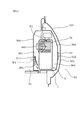
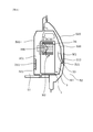
- the cross-sectional view of the rear seat air conditioning unit in the embodiment The longitudinal cross-sectional view of the rear-seat air conditioning unit when rotation of a rear blower fan is made into the positive direction in an Example.
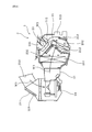
- the perspective view of the ceiling material in an Example The perspective view which shows the front side in a vehicle in an Example.
- the longitudinal cross-sectional view of the front seat air conditioning unit in an Example The cross-sectional schematic diagram of the vehicle in an Example.
- the vehicle air conditioner of the present invention can remarkably exert its function particularly in a vehicle having a rear seat air conditioning unit and having a relatively large cabin such as a minivan or SUV.
- This front seat air conditioning unit selectively opens and closes the inside air intake port for taking in the air inside the vehicle, the outside air intake port for taking in the air outside the vehicle, and the inside air intake port and the outside air intake port, thereby changing the intake mode to the inside air circulation mode.
- an inside / outside air switching door that switches to the outside air intake mode, and a front blower that takes in the outside air from the inside air inlet or takes in outside air from the outside air inlet and blows air,
- the ventilation switch By pressing the ventilation switch, the rotation direction of the rear blower fan is reversed, and at the same time, the front seat air conditioning unit operates the front blower while the intake mode preferentially becomes the outside air intake mode. It is preferable to blow outside air into the vehicle.
- outside air having a temperature lower than the temperature inside the vehicle can be introduced into the vehicle by the front seat air conditioning unit.
- the temperature in the vehicle can be further lowered before the air conditioner is started, and the cooling capacity of the air conditioner can be further improved.
- the front seat air conditioning unit and the rear seat air conditioning unit can be operated in cooperation such that the outside air is introduced into the vehicle and the hot air inside the vehicle is discharged outside the vehicle. Can be discharged more efficiently.
- the cover can be formed integrally with the rear seat air conditioning unit. In this case, maintenance of the rear seat air conditioning unit is facilitated, and it is not necessary to form a cover with a separate member, so that a low-cost air conditioning unit can be obtained.
- the ventilation switch can be operated by operating a remote control switch from outside the vehicle.
- the air conditioner of the present invention can be operated by pressing the ventilation switch before the passenger gets into the vehicle. Therefore, when the passenger gets in, the hot air inside the vehicle is sufficiently discharged, and thereafter, the air conditioner can be operated to sufficiently cool the inside of the vehicle so that the passenger can board comfortably.
- the vehicle air conditioner 1 of this example includes the following rear seat air conditioning unit 3, a ceiling air vent (see reference numeral 32 in FIG. 4), an in-vehicle communication port 501, and an exhaust air vent 33. , Cover 300, first butterfly damper 311, and second butterfly damper 312.
- the rear seat air conditioning unit 3 is provided on the rear side of the vehicle 5 and is disposed between a vehicle body outer plate 520 of the vehicle 5 and a trim 500 disposed on the inner side of the vehicle body outer plate 520. Further, the rear seat air conditioning unit 3 is configured so that the rotation direction of the rear blower fan 340 disposed so as to face the cover inner space 301 formed between the rear seat air conditioning unit 3 and the cover 300 is the forward direction (see FIG. 2).
- the rear blower 34 is configured to be switchable in the reverse direction (see the arrow R1 shown) or in the reverse direction (see the arrow R2 shown in FIG. 3).
- the rotation of the rear blower fan 340 is switched to the forward direction R ⁇ b> 1 or the reverse direction R ⁇ b> 2, so Or it can switch to positive pressure. That is, when the rotation direction of the rear blower fan 340 is the positive direction R1, the cover inner space 301 is negative pressure, and when the rotation direction is the negative direction R2, the cover inner space 301 is positive pressure.
- the ceiling air outlet 32 is connected to the air duct 321 disposed on the ceiling material 511 of the vehicle 5 from the rear seat air conditioning unit 3 at the ceiling of the vehicle 5.
- the ventilation duct 321 is connected to the following cover 300, as shown in FIG.
- the in-vehicle communication port 501 is formed in the trim 500 so as to communicate the rear seat air conditioning unit 3 and the in-vehicle 51 as shown in FIGS.
- the exhaust air blowing port 33 is formed in the cover 300 and is configured to be able to discharge the air sucked from the ceiling air blowing port 32 to the outside 52 of the vehicle.
- the first butterfly damper 311 is provided on the side where the rear seat air conditioning unit 3 is disposed in the in-car communication port 501.
- the second butterfly damper 312 is provided on the side of the exhaust air blowing port 33 opposite to the side where the rear seat air conditioning unit 3 is disposed.
- the cover 300 covers the rear seat air conditioning unit 3 in a state where at least the ceiling air vent 32, the in-vehicle communication port 501, and the exhaust air vent 33 are in communication.
- the ventilation switch (not shown) for ventilating operation is pushed, the rotation direction of the rear blower fan 340 is preferentially set to the reverse direction R2, and the cover inner space 301 is set to a positive pressure.
- the first butterfly damper 311 is closed to cover the in-vehicle communication port 501, and the second butterfly damper 312 is opened to open the exhaust air blowing port 33.
- the inside air is sucked from the ceiling blower port 32 (see the arrow w shown in FIG. 4), and the inside air is discharged from the exhaust blower port 33 (see the arrow W2 shown in FIGS. 1 and 3). Force ventilation. Details will be described below.
- the vehicle air conditioner 1 of the present example can exert its effects remarkably by applying it to a vehicle 5 having a large cabin such as a minivan or SUV as shown in FIG. This is because the vehicle 5 having a large cabin is generally provided with an air conditioning unit not only at the front but also at the rear. By operating these in conjunction with each other as described later, the hot air in the vehicle interior 51 is efficiently It is because it can discharge well. And the vehicle air conditioner 1 of this example has the following front seat air conditioning units 2 in addition to the rear seat air conditioning unit 3 and the ceiling air vent 32 described above.
- the front seat air conditioning unit 2 has the following components. That is, an engine room in which an engine (not shown) or the like is stored is provided in front of the interior 51 of the vehicle 5. Further, an instrument panel 512 in which an instrument 513 and an audio device 514 shown in FIG. 5 are accommodated is disposed in front of the vehicle interior 51, and a windshield 515 is fitted above the instrument panel 512.
- the front air outlet 23 through which air is blown out from the front seat air conditioning unit 2 is provided in the instrument panel 512 disposed in front of the vehicle interior 51 as shown in FIG. A front face blower opening 231 for blowing air.
- the ventilation opening is set to the defroster ventilation opening 232 or the front foot ventilation opening 233, as shown in FIG. 6, the front blowing outlet switching damper 212 provided in the front seat air conditioning unit 2 causes the ventilation The air passage in the front duct 21 can be switched so that the mouth becomes the front face air blowing port 231 preferentially.
- the front blower port 23 is blown from the defroster blower port 232 blown from under the windshield 515 or the feet of the passenger as shown in FIG.
- the front foot blower port 233 can also be used.
- the front seat air conditioning unit 2 has an inside / outside air switching door 211 for switching the intake mode between the inside air circulation mode and the outside air suction mode.
- the inside air inlet 221 for circulating the air (inside air) in the vehicle 51 is provided.
- the outside air inlet 222 and the inside air inlet 221 can be selectively opened and closed.
- the front seat air conditioning unit 2 includes an evaporator 251 and a heater core 252 in the front duct 21 and can be air-conditioned by passing through these.
- the evaporator 251 and the heater core 252 do not operate during forced ventilation.
- the rear seat air conditioning unit 3 is disposed between a vehicle body outer plate 520 of the vehicle 5 and a trim 500 described later, and is entirely covered with a cover 300. Yes.
- the cover 300 made of synthetic resin, for example, is arranged on the vehicle interior 51 side with respect to the vehicle body outer plate 520 and is in close contact with the trim 500 having a plurality of vehicle communication ports 501 communicating with the vehicle interior 51.
- the entire unit 3 is covered.
- the cover 300 has the exhaust ventilation port 33 on the opposite side to the side by which the trim 500 is distribute
- the cover 300 is formed integrally with the rear seat air conditioning unit 3, but may be formed integrally with the trim 500.
- the trim 500 can be used as the cover 300 by providing a space protruding to the outside 52 of the vehicle.
- the rear seat air conditioning unit 3 has the rear blower 34 as described above.
- the vehicle air conditioner 1 of this example is comprised so that the cover inner space 301 can be made into a positive pressure by making the rotation direction of the rear blower fan 340 of the said rear blower 34 into the reverse direction R2.
- the rear seat air conditioning unit 3 has a rear air outlet switching damper 35, which selectively opens and closes the ceiling air outlet 32 and the rear foot air outlet, and passes the inside air outlet mode through the ceiling air outlet 32.
- the mode is switched between the face mode and the foot mode via the rear foot outlet. That is, in the rear seat air conditioning unit 3, a ceiling air outlet 32 that blows out cool air from the ceiling and a rear foot air outlet that blows out toward the feet are connected to the air ducts 321 and 322, respectively, and these are connected by the rear air outlet switching damper 35. It is configured so that it can be switched.
- the rear seat air conditioning unit 3 has an evaporator 351 and a heater core 352 in addition to the above-described components, and can be air-conditioned by passing through these.
- the evaporator 351 and the heater core 352 do not operate during forced ventilation.
- the vehicle air conditioner 1 includes the ceiling blower port 32, the in-vehicle communication port 501, the exhaust blower port 33, the first butterfly damper 311, the second butterfly damper 312, and the cover 300 on the rear side of the vehicle 5. .
- the vehicle air conditioner 1 has a rear foot outlet (not shown) for blowing the inside air drawn from the vehicle interior 51 into the vehicle interior 51. And this rear foot blower outlet is connected with the ventilation duct 322 connected to the cover 300 similarly to the ventilation duct 321.
- the vehicle air conditioner 1 has the exhaust air blowing port 33, and the exhaust air blowing port 33 is connected to the louver 521 provided on the vehicle outer plate 520 through the exhaust duct 331.
- the ventilation switch is integrated with a remote control key for unlocking or locking the door of the vehicle 5. If it exists, it can also comprise so that a ventilation switch may be operated by remote control operation from the outside 52 of a vehicle.
- the front seat air conditioning unit 2 and the rear seat air conditioning unit 3 are configured to operate in cooperation by pressing a ventilation switch.
- the operation of the front seat air conditioning unit 2 will be described with reference to FIGS.
- FIG. 3 In the case where the front seat air conditioning unit 2 is set to take in the inside air from the inside air intake port 221 by pressing the ventilation switch, that is, when the inside air circulation mode is set, FIG.
- the inside / outside air switching door 211 shown in FIG. 3 is operated to switch the intake mode to the outside air intake mode for taking in outside air from the outside air inlet 222.
- the front air outlet switching damper 212 switches to the front face air outlet 231.
- the front seat air conditioning unit 2 operates the inside / outside air switching door 211 as described above, and simultaneously operates the front blower 24 to suck outside air into the front seat air conditioning unit 2 from the outside air intake port 222.
- the outside air sucked into the seat air conditioning unit 2 is blown from the front blower opening 23 to the vehicle interior 51 (see arrow W3 in FIGS. 5 to 7).
- the operation of the equipment provided on the rear side of the rear seat air conditioning unit 3 and the vehicle 5 will be described with reference to FIGS.
- the rear seat air conditioning unit 3 first, a state in which the ventilation switch is not pressed and the inside air blowing mode to the vehicle interior 51 is described.
- the inside air blowing mode since the rotation direction of the rear blower fan 340 is the positive direction R1, the cover inner space 301 has a negative pressure. Therefore, as shown in FIG. 2, the first butterfly damper 311 is opened and the in-vehicle communication port 501 is opened, the second butterfly damper 312 is closed and the exhaust air blowing port 33 is covered.
- the inside air is sucked from the interior 51 of the vehicle, which is positive with respect to the cover interior space 301, via the interior communication port 501 (see arrow W1 shown in FIG. 2).
- the sucked inside air passes through the rear blower 34 and the evaporator 351 and is cooled, and then passes through the blower duct 321 and is blown from the ceiling blower port 32 (see the arrow W1 shown in FIGS. 1 and 2).
- the rear air outlet switching damper 35 is set to open the air duct 322 side, and the inside air blowing mode is the foot mode.
- the rear seat air conditioning unit 3 operates as follows simultaneously with the operation of the front seat air conditioning unit 2 when the ventilation switch is pressed. That is, when the ventilation switch is pressed and the inside air blowing mode is set to the foot mode via the air duct 322 connected to the rear foot outlet, the rear seat air conditioning unit 3 switches the rear outlet.
- the damper 35 is operated so that the inside air blowing mode is switched to the face mode via the air duct 321 connected to the ceiling air outlet 32 preferentially.
- the rotation direction of the rear blower fan 340 is set to the reverse rotation R2, and the cover inner space 301 is set to a positive pressure, whereby the first butterfly damper 311 is closed and the in-car communication port 501 is closed, and the second butterfly damper 312 is It opens and the exhaust vent 33 is opened.
- the air blowing mode is switched to the exhaust mode so that the inside air drawn into the cover inner space 301 from the ceiling air blowing port 32 flows to the exhaust air blowing port 33. That is, when the ventilation switch is pressed, the air blowing path is switched from the broken line arrow W1 in FIGS. 1 and 2 to the solid line arrow W2 in FIGS.
- the vehicle air conditioner 1 operates the first butterfly damper 311 and the second butterfly damper 312 by the operation of the rear blower 34 as described above, and simultaneously covers the air in the vehicle 51 from the ceiling air outlet 32 by the operation of the rear blower 34. Intake into the inner space 301 (see arrow w in FIG. 4) and the inside air sucked into the cover inner space 301 are discharged from the exhaust air blowing port 33 (see arrow W2 in FIG. 3).
- the hot air is then discharged from the louver 521 provided on the vehicle outer plate 520 to the vehicle exterior 52.
- hot air inside the vehicle 51 particularly hot air on the ceiling of the vehicle 5, can be discharged to the outside 52 of the vehicle.
- the ventilation switch is pressed to rotate the rear blower fan 340 in the reverse direction R2, thereby closing the first butterfly damper 311 to cover the in-vehicle communication port 501 and opening the second butterfly damper 312 to exhaust the exhaust vent.
- the inside air is sucked from the ceiling air blowing port 32 and the inside air is discharged from the exhaust air blowing port 33 to forcibly ventilate the interior 51 of the vehicle.
- the cover inner space 301 can be set to a positive pressure by setting the rotation direction of the rear blower fan 340 to the reverse direction R2 as described above. For this reason, it is possible to send air from the cover inner space 301 toward the vehicle interior 51 or the vehicle exterior 52, which has a negative pressure compared to the cover internal space 301. Therefore, the first butterfly damper 311 is closed by being pushed by the air toward the vehicle interior 51 and covers the in-car communication port 501, while the second butterfly damper 312 is opened by being pushed by the air toward the vehicle exterior 52 and the exhaust air blowing port. 33 is released.
- the rear blower fan 340 rotates to suck the hot air in the vehicle interior 51, particularly the hot air in the upper portion of the vehicle interior 51, from the ceiling air outlet 32 into the rear seat air conditioning unit 3. Can be discharged.
- the temperature of the vehicle interior 51 can be sufficiently lowered to improve the cooling capacity of the air conditioner.
- the air conditioner of this example when hot air accumulates in the vehicle interior 51, particularly the ceiling, when the vehicle is stopped, the air conditioner of this example is operated before the air conditioner is started to forcibly exhaust the hot air to the outside 52 and ventilate the vehicle interior 51. it can.
- the heat load acting on the air conditioner when the air conditioner is started can be sufficiently reduced, and the cooling capacity can be greatly improved.
- the vehicle interior 51 can be quickly brought to a comfortable temperature.
- the pressure in the cover inner space 301 is changed to open and close the two butterfly dampers 311 and 312 only by switching the rotation direction of the rear blower fan 340 without controlling the switching damper and the servo motor.
- the hot air inside the vehicle 51 can be discharged to the outside 52 of the vehicle.
- the vehicle air conditioner 1 having the above-described excellent ventilation function can be obtained with a simple structure in which the rotation direction of the rear blower fan 340 is switched and the pressure in the cover inner space 301 is changed. it can.
- the cover 300 covers the rear seat air conditioning unit 3 with at least the ceiling air vent 32, the in-vehicle communication port 501, and the exhaust air vent 33 communicating.
- emission capability of the vehicle air conditioner 1 can be improved. That is, by the cover 300, only hot air in the vehicle interior 51 can be efficiently sucked into the cover inner space 301 without sucking extra hot air. In addition, this eliminates the need to use an air conditioner with a high cooling capacity, thereby reducing the cost of the air conditioner.
- the vehicle air conditioner 1 of this example includes the front seat air conditioning unit 2 described above.
- the outside air at a temperature lower than the temperature in the vehicle interior 51 can be introduced into the vehicle interior 52 by the front seat air conditioning unit 2.
- the temperature of the vehicle interior 51 can be further lowered before the air conditioner is started, and the cooling capacity of the air conditioner can be further improved.
- the front seat air conditioning unit 2 and the rear seat air conditioning unit 3 can be operated in cooperation such that the outside air is introduced into the vehicle interior 51 and the hot air in the vehicle interior 51 is discharged to the vehicle exterior 52. Therefore, the hot air in the vehicle 51 can be discharged more efficiently.
Landscapes
- Physics & Mathematics (AREA)
- Thermal Sciences (AREA)
- Engineering & Computer Science (AREA)
- Mechanical Engineering (AREA)
- Air-Conditioning For Vehicles (AREA)
Abstract
車両用空調装置1は、後席空調ユニット3と送風ダクト321と天井送風口32と車内連通口501と排気送風口33と第一バタフライダンパ311と第二バタフライダンパ312とカバー300とを有する。リアブロア34は、カバー内空間301に面するよう配置されたリアブロアファン340の回転方向を正逆切り替えてカバー内空間301を負圧又は正圧にすることができる。リアブロアファン340の回転方向を逆方向としてカバー内空間301を正圧にすることにより、第一バタフライダンパ311を閉じて車内連通口501を覆い第二バタフライダンパ312を開いて排気送風口33を開放し、天井送風口32から内気を吸入し排気送風口33から内気を排出して、車内51を強制換気できるよう構成されている。
Description
本発明は、強制換気機能を有する車両用空調装置に関する。
従来、夏の炎天下などにおいては、車内の温度が非常に高温となり、特に温度を感じやすい車内の上部に熱気がたまりやすく、不快に感じることがあった。そして、乗車した直後に空調装置(エアコン)を作動させても車内が冷却されるまでは多大な時間がかかっていた。さらに、車両天井にクーラダクトが配設されている場合には、炎天下における車両放置によりクーラダクト内に熱気がたまり、エアコン作動直後に暖かい風が吹き出るため不快となっていた。
そこで、従来においては、手動でドアを開閉して車内の換気を行ったり、停車中に窓を開けっ放しにしたりしてその熱気を排出していた。ところが、その操作が煩わしく、また、駐車スペース及び防犯上の制約などもあった。かかる問題は、特にキャビンが大きなミニバンやSUV(スポーツ・ユーティリティ・ビークル)などにおいて顕著に生じる問題である。
これに対し、エアコン始動前に所定時間、車両の後方に配される後席空調ユニット内に設けられたリアブロアを駆動して車内の熱気を排出させる熱気排出手段を有する空調装置が提案されている(特許文献1参照)。また、空調ユニット内に設けられたブロア装置に備えつけられた直流モータ装置の回転方向を正方向又は逆方向に切り替えるよう構成された空調装置が提案されている(特許文献2参照)。さらに、リモート作動によるソーラー駐車換気システムとプレ空調とを組み合わせて熱気を排出することも考えられている。
ところが、特許文献1に記載の従来技術においては、以下のような問題点があった。すなわち、この従来技術においては、換気機能を作動させるための切替ダンパやサーボモータなどが必要であり、さらに、これらを制御する制御手段をも設けると、コストが高くなってしまうおそれがあった。
また、特許文献2に記載の従来技術は、ブロアファンの回転方向を正逆切り替えることにより車内への送風又は車外への排出を切り替えることができるというにすぎない。
また、特許文献2に記載の従来技術は、ブロアファンの回転方向を正逆切り替えることにより車内への送風又は車外への排出を切り替えることができるというにすぎない。
さらに、ソーラー駐車換気システムとプレ空調とを組み合わせた場合にあっては、車両重量が重くなり、また、それが専用品であるため、換気システムのコストが増大してしまうという問題があった。またさらに、これらの制御が複雑となってしまうという問題もあった。
したがって、従来においては、低コストであって、エアコンの冷却能力を十分に向上させることができる車両用空調装置を提供できるとは言いがたかった。
したがって、従来においては、低コストであって、エアコンの冷却能力を十分に向上させることができる車両用空調装置を提供できるとは言いがたかった。
本発明は、かかる従来の問題点に鑑みてなされたもので、低コストであって、エアコン始動前に車内の温度を下げてエアコンの冷却能力を向上させることができる車両用空調装置を提供しようとするものである。
本発明は、車内の後方側に備えつけられる後席空調ユニットと、該後席空調ユニットから配設される送風ダクトと車両の天井において接続される天井送風口と、上記後席空調ユニットと車内とを連通させる車内連通口と、上記天井送風口から吸入した空気を車外に排出する排気送風口と、少なくとも上記天井送風口と上記車内連通口と上記排気送風口とを連通させた状態で上記後席空調ユニットを覆うカバーと、上記車内連通口における上記後席空調ユニットが配される側に設けられた第一バタフライダンパと、上記排気送風口における上記後席空調ユニットが配される側と反対側に設けられた第二バタフライダンパと、を有し、
上記後席空調ユニットは、該後席空調ユニットと上記カバーとの間に形成されるカバー内空間に面するよう配置されたリアブロアファンの回転方向を正方向又は逆方向に切り替えることができるよう構成されたリアブロアを有し、
換気スイッチを押して上記リアブロアファンの回転方向を優先的に逆方向として上記カバー内空間を正圧にすることにより、上記第一バタフライダンパを閉じて上記車内連通口を覆うとともに上記第二バタフライダンパを開いて上記排気送風口を開放し、この状態で上記天井送風口から内気を吸入するとともに上記排気送風口からこの内気を排出して、車内を強制換気することができるよう構成されていることを特徴とする車両用空調装置にある。
上記後席空調ユニットは、該後席空調ユニットと上記カバーとの間に形成されるカバー内空間に面するよう配置されたリアブロアファンの回転方向を正方向又は逆方向に切り替えることができるよう構成されたリアブロアを有し、
換気スイッチを押して上記リアブロアファンの回転方向を優先的に逆方向として上記カバー内空間を正圧にすることにより、上記第一バタフライダンパを閉じて上記車内連通口を覆うとともに上記第二バタフライダンパを開いて上記排気送風口を開放し、この状態で上記天井送風口から内気を吸入するとともに上記排気送風口からこの内気を排出して、車内を強制換気することができるよう構成されていることを特徴とする車両用空調装置にある。
本発明においては、換気スイッチを押して上記リアブロアファンの回転を逆方向として上記カバー内空間を正圧にすることにより、上記第一バタフライダンパを閉じて上記車内連通口を覆うとともに上記第二バタフライダンパを開いて上記排気送風口を開放し、この状態で上記天井送風口から内気を吸入するとともに上記排気送風口からこの内気を排出して、車内を強制換気する。これにより、低コストであって、エアコン始動前に車内の温度を下げてエアコンの冷却能力を向上させることができる車両用空調装置を提供することができる。
すなわち、本発明においては、上記のとおりリアブロアファンの回転方向を逆方向とすることにより、カバー内空間を正圧とすることができる。このため、カバー内空間に比して負圧である車内又は車外に向かって、カバー内空間から空気を送り出すようにすることができる。そのため、車内に向かう空気によって押されることにより第一バタフライダンパが閉じて車内連通口を覆い、一方、車外に向かう空気によって押されることにより第二バタフライダンパが開いて排気送風口を開放する。また、これと同時にリアブロアファンが回転することにより天井送風口からカバー内空間へ車内の熱気、特に車内上部の熱気が吸入されて、さらにそれを排気送風口から排出することができる。このように本発明によれば、エアコン始動前に車内の熱気を車外へと放出することにより、車内の温度を十分に下げてエアコンの冷却能力を向上させることができる。
すなわち、停車中に車内、特に天井に熱気が溜まった場合、エアコン始動前に本発明の空調装置を作動させてその熱気を強制的に車外へと排出して車内を換気することができる。このようにして、車内を換気した後においては、エアコン始動時においてエアコンに作用する熱負荷を十分に小さくすることができ、その冷却能力を格段に向上させることができる。そして、車内に搭乗者が乗り込んですぐに車内を早期に快適な温度となるようにすることができる。
また、従来とは異なり切替ダンパやサーボモータなどの制御を行うことなくリアブロアファンの回転方向を切り替えるだけで、カバー内空間の圧力を変化させて上記二つのバタフライダンパを開閉して車内の熱気を車外へと排出することができる。このように、リアブロアファンの回転方向を切り替えてカバー内空間の圧力を変化させるだけの簡易な構造にて、上記のような優れた換気機能を有する車両用空調装置を得ることができる。
さらに、本発明においては、上記カバーが少なくとも上記天井送風口と上記車内連通口と上記排気送風口とを連通させた状態で上記後席空調ユニットを覆っている。これにより、車両用空調装置の熱気排出能力を向上させることができる。すなわち、上記カバーにより、余分な熱気を吸入することなく車内の熱気のみを効率良くカバー内空間に吸入することができる。さらにこれにより、冷却能力の高いエアコンを使用する必要がなくなるため、エアコンの低コスト化を図ることもできる。
以上のとおり、本発明によれば、低コストであって、エアコン始動前に車内の温度を下げてエアコンの冷却能力を向上させることができる車両用空調装置を提供することができる。
本発明の車両用空調装置は、後席空調ユニットを有する、特にミニバンやSUVなどのようにキャビンが比較的大きい車両においてその機能を顕著に発揮することができる。
また、車内の前方側に備えつけられる前席空調ユニットを有し、
この前席空調ユニットは、車内の空気を取り込む内気吸入口と、車外の空気を取り込む外気吸入口と、上記内気吸入口と上記外気吸入口とを選択的に開閉して吸気モードを内気循環モード又は外気吸入モードに切り替える内外気切替ドアと、上記内気吸入口から内気を又は上記外気吸入口から外気を取り込んで送風を行うフロントブロアとを有し、
上記換気スイッチを押すことにより、上記リアブロアファンの回転方向を逆方向にするのと同時に、上記前席空調ユニットは、上記吸気モードが優先的に上記外気吸入モードとなるとともに上記フロントブロアを作動させて車内に外気を送風することが好ましい。
この前席空調ユニットは、車内の空気を取り込む内気吸入口と、車外の空気を取り込む外気吸入口と、上記内気吸入口と上記外気吸入口とを選択的に開閉して吸気モードを内気循環モード又は外気吸入モードに切り替える内外気切替ドアと、上記内気吸入口から内気を又は上記外気吸入口から外気を取り込んで送風を行うフロントブロアとを有し、
上記換気スイッチを押すことにより、上記リアブロアファンの回転方向を逆方向にするのと同時に、上記前席空調ユニットは、上記吸気モードが優先的に上記外気吸入モードとなるとともに上記フロントブロアを作動させて車内に外気を送風することが好ましい。
この場合には、前席空調ユニットによって車内の温度よりも低温の外気を車内に導入することができる。これにより、エアコン始動前に車内の温度を一層下げて、エアコンの冷却能力を一層向上させることができる。
さらに、本発明においては、外気を車内に導入しつつ車内の熱気を車外に排出するというように前席空調ユニットと後席空調ユニットとを協働して作動させることができるため、車内の熱気を一層効率良く排出することができる。
さらに、本発明においては、外気を車内に導入しつつ車内の熱気を車外に排出するというように前席空調ユニットと後席空調ユニットとを協働して作動させることができるため、車内の熱気を一層効率良く排出することができる。
また、上記カバーは、上記後席空調ユニットと一体的に形成することができる。
この場合には、後席空調ユニットのメンテナンスが容易となり、さらに別部材によりカバーを形成する必要がないため、低コストの空調ユニットを得ることができる。
この場合には、後席空調ユニットのメンテナンスが容易となり、さらに別部材によりカバーを形成する必要がないため、低コストの空調ユニットを得ることができる。
また、上記換気スイッチは、車外からのリモコンスイッチ操作により動作させることができる。
この場合には、搭乗者が車両に乗り込む前に換気スイッチを押して本発明の空調装置を作動させることができる。したがって、搭乗者が乗り込む際には車内の熱気は十分に排出されているため、その後はエアコンを作動させて車内を十分に冷却して快適に搭乗することができる。
この場合には、搭乗者が車両に乗り込む前に換気スイッチを押して本発明の空調装置を作動させることができる。したがって、搭乗者が乗り込む際には車内の熱気は十分に排出されているため、その後はエアコンを作動させて車内を十分に冷却して快適に搭乗することができる。
本発明の車両用空調装置に係る実施例について、図1~図7とともに説明する。
図1に示すように、本例の車両用空調装置1は、下記の後席空調ユニット3と、天井送風口(図4における符号32参照)と、車内連通口501と、排気送風口33と、カバー300と、第一バタフライダンパ311と、第二バタフライダンパ312とを有する。
図1に示すように、本例の車両用空調装置1は、下記の後席空調ユニット3と、天井送風口(図4における符号32参照)と、車内連通口501と、排気送風口33と、カバー300と、第一バタフライダンパ311と、第二バタフライダンパ312とを有する。
後席空調ユニット3は、車両5の後方側に備えつけられるとともに、車両5の車体外板520とこの車体外板520よりも内側に配されるトリム500との間に配設されている。
また、後席空調ユニット3は、この後席空調ユニット3とカバー300との間に形成されるカバー内空間301に面するよう配置されたリアブロアファン340の回転方向を正方向(図2に示す矢印R1参照)又は逆方向(図3に示す矢印R2参照)に切り替えることができるよう構成されたリアブロア34を有する。
また、後席空調ユニット3は、この後席空調ユニット3とカバー300との間に形成されるカバー内空間301に面するよう配置されたリアブロアファン340の回転方向を正方向(図2に示す矢印R1参照)又は逆方向(図3に示す矢印R2参照)に切り替えることができるよう構成されたリアブロア34を有する。
そして、本例の車両用空調装置1においては、図2、図3に示すように、リアブロアファン340の回転方向を正方向R1又は逆方向R2に切り替えることにより、カバー内空間301を負圧又は正圧に切り替えることができる。すなわち、リアブロアファン340の回転方向を正方向R1とした場合、カバー内空間301は負圧となり、上記回転方向を負方向R2とした場合、カバー内空間301は正圧となる。
また、上記天井送風口32は、図4に示すように、後席空調ユニット3から車両5の天井材511に配設される送風ダクト321と車両5の天井において接続されている。そして、送風ダクト321は、図1に示すように、下記のカバー300に接続されている。
また、本例において車内連通口501は、図1~図3に示すように、トリム500に形成されて後席空調ユニット3と車内51とを連通するよう形成されている。
また、排気送風口33は、カバー300に形成され、天井送風口32から吸入した空気を車外52に排出することができるよう構成されている。
また、本例において車内連通口501は、図1~図3に示すように、トリム500に形成されて後席空調ユニット3と車内51とを連通するよう形成されている。
また、排気送風口33は、カバー300に形成され、天井送風口32から吸入した空気を車外52に排出することができるよう構成されている。
第一バタフライダンパ311は、図1~図3に示すように、車内連通口501における後席空調ユニット3が配される側に設けられている。
また、第二バタフライダンパ312は、排気送風口33における後席空調ユニット3が配される側と反対側に設けられている。
カバー300は、少なくとも天井送風口32と車内連通口501と排気送風口33とを連通させた状態で後席空調ユニット3を覆っている。
また、第二バタフライダンパ312は、排気送風口33における後席空調ユニット3が配される側と反対側に設けられている。
カバー300は、少なくとも天井送風口32と車内連通口501と排気送風口33とを連通させた状態で後席空調ユニット3を覆っている。
そして、本例の車両用空調装置1においては、換気作動させるための換気スイッチ(図示略)を押してリアブロアファン340の回転方向を優先的に逆方向R2としてカバー内空間301を正圧にすることにより、図3に示すように、第一バタフライダンパ311を閉じて車内連通口501を覆うとともに第二バタフライダンパ312を開いて排気送風口33を開放する。そしてこの状態で、天井送風口32から内気を吸入する(図4に示す矢印w参照)とともに排気送風口33からこの内気を排出して(図1、図3に示す矢印W2参照)、車内51を強制換気する。
以下、詳細に説明する。
以下、詳細に説明する。
<車両用空調装置の構成>
本例の車両用空調装置1は、図7に示すような、例えば、ミニバンやSUVなどのようにキャビンが大きな車両5に適用することにより、その作用効果を顕著に発揮することができる。これは、このようにキャビンの大きな車両5には、一般にフロントのみならずリアにも空調ユニットが配設されており、これらを後述するよう連動して作動させることで、車内51の熱気を効率良く排出できるからである。
そして、本例の車両用空調装置1は、前述した後席空調ユニット3や天井送風口32などのほか、下記の前席空調ユニット2を有する。
本例の車両用空調装置1は、図7に示すような、例えば、ミニバンやSUVなどのようにキャビンが大きな車両5に適用することにより、その作用効果を顕著に発揮することができる。これは、このようにキャビンの大きな車両5には、一般にフロントのみならずリアにも空調ユニットが配設されており、これらを後述するよう連動して作動させることで、車内51の熱気を効率良く排出できるからである。
そして、本例の車両用空調装置1は、前述した後席空調ユニット3や天井送風口32などのほか、下記の前席空調ユニット2を有する。
まず、前席空調ユニット2について、図5、図6とともに説明する。
前席空調ユニット2は、以下のような構成要素を有する。
すなわち、車両5の車内51の前方には、図示しないエンジンなどが収納されるエンジン室が設けられている。また、車内51の前方には図5に示す計器513やオーディオ機器514が収納されるインストルメントパネル512が配置され、このインストルメントパネル512の上方にフロントガラス515が嵌め込まれている。
前席空調ユニット2は、以下のような構成要素を有する。
すなわち、車両5の車内51の前方には、図示しないエンジンなどが収納されるエンジン室が設けられている。また、車内51の前方には図5に示す計器513やオーディオ機器514が収納されるインストルメントパネル512が配置され、このインストルメントパネル512の上方にフロントガラス515が嵌め込まれている。
本例では、前席空調ユニット2から空気が吹き出されるフロント送風口23は、図5に示すように、車内51の前方に配設されるインストルメントパネル512に設けられ、搭乗者に向かって送風するフロントフェイス送風口231である。なお、デフロスタ送風口232やフロントフット送風口233に送風口が設定されている場合には、図6に示すように、前席空調ユニット2内に設けられたフロント吹出口切替ダンパ212によって、送風口が優先的にフロントフェイス送風口231となるようにフロントダクト21内の空気の通路を切り替えることができるよう構成されている。
なお、上記フロント送風口23は、上記のとおりフロントフェイス送風口231のほか、図5に示すように、フロントガラス515の下から送風されるデフロスタ送風口232や、搭乗者の足元から送風されるフロントフット送風口233とすることもできる。
また、前席空調ユニット2は、図6に示すように、吸気モードを内気循環モードと外気吸入モードとを切り替えるための内外気切替ドア211を有する。具体的には、車外52の空気を取り込むための外気吸入口222のほか、車内51の空気(内気)を循環させるための内気吸入口221を有する。そして、上記内外気切替ドア211を用いることにより、外気吸入口222と、内気吸入口221とを選択的に開閉することができるよう構成されている。
また、前席空調ユニット2は、上記のほか、フロントダクト21内にエバポレータ251やヒータコア252を有し、これらを通過することにより空調することができる。ただし、本例において、強制換気中は、エバポレータ251やヒータコア252などは作動
しない。
しない。
次に、後席空調ユニット3及び車両用空調装置1における車両5の後方側に備えつけられた設備について、図1~図4とともに説明する。
また、後席空調ユニット3は、図1~図3に示すように、車両5の車体外板520と後述するトリム500との間に配設されるとともに、その全体がカバー300で覆われている。
また、後席空調ユニット3は、図1~図3に示すように、車両5の車体外板520と後述するトリム500との間に配設されるとともに、その全体がカバー300で覆われている。
具体的には、例えば合成樹脂からなるカバー300は、車体外板520よりも車内51側に配され車内51と連通する複数の車内連通口501を有するトリム500に密接した状態で、後席空調ユニット3の全体を覆っている。そして、カバー300は、トリム500が配される側と反対側に排気送風口33を有する。そしてさらに、カバー300によって後席空調ユニット3の全体を覆うことにより、図1に示すように、カバー300の内側と天井送風口32と車内連通口501と排気送風口33とを連通させて空気の通路が形成されている。
なお、本例では、カバー300は、後席空調ユニット3と一体的に形成したが、トリム500と一体的に形成することもできる。具体的には、本明細書にては図示はしないが、トリム500に、車外52へと突出する空間を設けてそれをカバー300として使用することができる。
また、後席空調ユニット3は、前述したとおり、リアブロア34を有する。そして、本例の車両用空調装置1は、上記リアブロア34のリアブロアファン340の回転方向を逆方向R2にすることにより、カバー内空間301を正圧にすることができるよう構成されている。
また、後席空調ユニット3は、リア吹出口切替ダンパ35を有し、それによって天井送風口32と上記リアフット吹出口とを選択的に開閉して、内気吹出モードを天井送風口32を経由するフェイスモードと、上記リアフット吹出口を経由するフットモードとに切り替えている。すなわち、後席空調ユニット3は、天井から冷気を吹き出す天井送風口32と、足元に向かって吹出すリアフット吹出口とがそれぞれ送風ダクト321、322に接続され、リア吹出口切替ダンパ35によりこれらを切り替えることができるよう構成されている。
さらに、後席空調ユニット3は、上記構成要素のほか、エバポレータ351やヒータコア352を有し、これらを通過することにより空調することができる。ただし、本例において、強制換気中は、エバポレータ351やヒータコア352などは作動しない。
次いで、車両用空調装置1の後方側の設備について簡単に説明する。車両用空調装置1は、前述したとおり、車両5の後方側において、天井送風口32と車内連通口501と排気送風口33と第一バタフライダンパ311と第二バタフライダンパ312とカバー300とを有する。
また、車両用空調装置1は、前述した構成要素のほか、車内51から吸入した内気を車内51へ吹き出すためのリアフット吹出口(図示略)を有している。そして、このリアフット吹出口は、送風ダクト321と同様カバー300に接続される送風ダクト322に連結されている。
また、前述したとおり車両用空調装置1は排気送風口33を有し、この排気送風口33は、排気ダクト331を介して車両外板520に設けられたルーバ521に接続されている。
また、前述したとおり車両用空調装置1は排気送風口33を有し、この排気送風口33は、排気ダクト331を介して車両外板520に設けられたルーバ521に接続されている。
<本例の車両用空調装置の動作について>
次に、本例の車両用空調装置1の動作について、図1~図7とともに説明する。
まず、運転手が車両5に乗り込み、インストルメントパネル512に備えつけられた換気スイッチ(図示略)を押す。
次に、本例の車両用空調装置1の動作について、図1~図7とともに説明する。
まず、運転手が車両5に乗り込み、インストルメントパネル512に備えつけられた換気スイッチ(図示略)を押す。
なお、本例においては、上記のとおり運転手が車両5に乗り込んだ後に換気スイッチを押すこととしたが、換気スイッチを、車両5のドアを開錠又は施錠するリモートコントロールキーと一体化させてあれば、車外52からのリモコン操作により、換気スイッチを動作するよう構成することもできる。
本例においては、換気スイッチを押すことにより、前席空調ユニット2と後席空調ユニット3とが協働して作動するよう構成されている。
そこでまず、前席空調ユニット2の動作について、図5~図7とともに説明する。
そこでまず、前席空調ユニット2の動作について、図5~図7とともに説明する。
前席空調ユニット2は、換気スイッチが押されることにより、吸気モードが内気吸入口221から内気を取り込むように設定されている場合、すなわち、内気循環モードに設定されている場合には、図6に示す内外気切替ドア211を作動させて吸気モードを外気吸入口222から外気を取り込む外気吸入モードへ切り替える。
また、送風口がフロントフット送風口233などに設定されている場合には、フロント吹出口切替ダンパ212によってフロントフェイス送風口231に切り替える。
また、送風口がフロントフット送風口233などに設定されている場合には、フロント吹出口切替ダンパ212によってフロントフェイス送風口231に切り替える。
また、前席空調ユニット2は、上記のとおり内外気切替ドア211を作動させると同時に、フロントブロア24を作動させて外気を外気吸入口222から前席空調ユニット2内に吸入するとともに、この前席空調ユニット2内に吸入された外気をフロント送風口23から車内51に送風する(図5~図7における矢印W3参照)。
次に、後席空調ユニット3及び車両5の後方側に備えつけられた設備の動作について、図1~図4とともに説明する。
後席空調ユニット3については、まず、換気スイッチが押されておらず車内51への内気吹出モードになっている状態について説明する。かかる内気吹出モードにおいては、リアブロアファン340の回転方向は正方向R1となっているため、カバー内空間301は負圧となる。そのため、図2に示すように、第一バタフライダンパ311は開いて車内連通口501が開放され、第二バタフライダンパ312が閉じて排気送風口33が覆われている。
後席空調ユニット3については、まず、換気スイッチが押されておらず車内51への内気吹出モードになっている状態について説明する。かかる内気吹出モードにおいては、リアブロアファン340の回転方向は正方向R1となっているため、カバー内空間301は負圧となる。そのため、図2に示すように、第一バタフライダンパ311は開いて車内連通口501が開放され、第二バタフライダンパ312が閉じて排気送風口33が覆われている。
そして、この状態でカバー内空間301に対して正圧である車内51から車内連通口501を経由して内気を吸入する(図2に示す矢印W1参照)。この吸入された内気は、リアブロア34やエバポレータ351などを通過して冷却され、その後、送風ダクト321を通過して天井送風口32から送風される(図1、図2に示す矢印W1参照)。
なお、リア吹出口切替ダンパ35が送風ダクト322側を開放するよう設定されて内気吹出モードがフットモードとなっている場合もある。
なお、リア吹出口切替ダンパ35が送風ダクト322側を開放するよう設定されて内気吹出モードがフットモードとなっている場合もある。
これに対して、後席空調ユニット3は換気スイッチが押されることにより、上記前席空調ユニット2が作動するのと同時に以下のように動作する。
すなわち、換気スイッチが押されることにより、内気吹出モードが上記リアフット吹出口と接続される送風ダクト322を経由するフットモードに設定されている場合には、後席空調ユニット3は、リア吹出口切替ダンパ35を作動させて、内気吹出モードが優先的に天井送風口32と接続される送風ダクト321を経由するフェイスモードとなるように切り替える。
すなわち、換気スイッチが押されることにより、内気吹出モードが上記リアフット吹出口と接続される送風ダクト322を経由するフットモードに設定されている場合には、後席空調ユニット3は、リア吹出口切替ダンパ35を作動させて、内気吹出モードが優先的に天井送風口32と接続される送風ダクト321を経由するフェイスモードとなるように切り替える。
またそれとともに、リアブロアファン340の回転方向を逆回転R2としてカバー内空間301を正圧とすることで、第一バタフライダンパ311を閉じて車内連通口501が閉じられ、第二バタフライダンパ312を開いて排気送風口33が開かれる。このように天井送風口32からカバー内空間301に吸入された内気が排気送風口33へと流れるよう、送風モードを排気モードに切り替える。すなわち、換気スイッチを押すことにより、送風経路が、図1、図2における破線矢印W1から、図1、図3における実線矢印W2へと切り替わる。
また、車両用空調装置1は、上記のとおりリアブロア34の動作により第一バタフライダンパ311及び第二バタフライダンパ312を作動させると同時に、リアブロア34の動作により車内51の空気を天井送風口32からカバー内空間301に吸入する(図4における矢印w参照)とともにカバー内空間301に吸入した内気を排気送風口33から排出する(図3における矢印W2参照)。
そして、その後熱気は、図1、図3に示すように、車両外板520に設けられたルーバ521から車外52に排出される。
以上の動作により、車内51の熱気、特に車両5の天井の熱気を車外52へと排出することができる。
以上の動作により、車内51の熱気、特に車両5の天井の熱気を車外52へと排出することができる。
以下に、本例の作用効果について説明する。
本例においては、換気スイッチを押してリアブロアファン340の回転を逆方向R2とすることにより、第一バタフライダンパ311を閉じて車内連通口501を覆うとともに第二バタフライダンパ312を開いて排気送風口33を開放し、この状態で天井送風口32から内気を吸入するとともに排気送風口33からこの内気を排出して、車内51を強制換気する。これにより、低コストであって、エアコン始動前に車内51の温度を下げてエアコンの冷却能力を向上させることができる車両用空調装置1を提供することができる。
本例においては、換気スイッチを押してリアブロアファン340の回転を逆方向R2とすることにより、第一バタフライダンパ311を閉じて車内連通口501を覆うとともに第二バタフライダンパ312を開いて排気送風口33を開放し、この状態で天井送風口32から内気を吸入するとともに排気送風口33からこの内気を排出して、車内51を強制換気する。これにより、低コストであって、エアコン始動前に車内51の温度を下げてエアコンの冷却能力を向上させることができる車両用空調装置1を提供することができる。
すなわち、本例においては、上記のとおりリアブロアファン340の回転方向を逆方向R2とすることにより、カバー内空間301を正圧とすることができる。このため、カバー内空間301に比して負圧である車内51又は車外52に向かって、カバー内空間301から空気を送り出すようにすることができる。そのため、車内51に向かう空気によって押されることにより第一バタフライダンパ311が閉じて車内連通口501を覆い、一方、車外52に向かう空気によって押されることにより第二バタフライダンパ312が開いて排気送風口33を開放する。また、これらと同時にリアブロアファン340が回転することにより天井送風口32から後席空調ユニット3内へ車内51の熱気、特に車内51上部の熱気が吸入されて、さらにそれを排気送風口33から排出することができる。このように本例によれば、エアコン始動前に車内51の熱気を車外へと放出することにより、車内51の温度を十分に下げてエアコンの冷却能力を向上させることができる。
すなわち、停車中に車内51、特に天井に熱気が溜まった場合、エアコン始動前に本例の空調装置を作動させてその熱気を強制的に車外52へと排出して車内51を換気することができる。このようにして、車内51を換気した後においては、エアコン始動時においてエアコンに作用する熱負荷を十分に小さくすることができ、その冷却能力を格段に向上させることができる。そして、車内51に搭乗者が乗り込んですぐに車内51を早期に快適な温度となるようにすることができる。
また、従来とは異なり切替ダンパやサーボモータなどの制御を行うことなくリアブロアファン340の回転方向を切り替えるだけで、カバー内空間301の圧力を変化させて上記二つのバタフライダンパ311、312を開閉して車内51の熱気を車外52へと排出することができる。このように、リアブロアファン340の回転方向を切り替えてカバー内空間301の圧力を変化させるだけの簡易な構造にて、上記のような優れた換気機能を有する車両用空調装置1を得ることができる。
さらに、本例においては、カバー300が少なくとも天井送風口32と車内連通口501と排気送風口33とを連通させた状態で後席空調ユニット3を覆っている。これにより、車両用空調装置1の熱気排出能力を向上させることができる。すなわち、カバー300により、余分な熱気を吸入することなく車内51の熱気のみを効率良くカバー内空間301に吸入することができる。さらにこれにより、冷却能力の高いエアコンを使用する必要がなくなるため、エアコンの低コスト化を図ることもできる。
また、本例の車両用空調装置1は、上記の前席空調ユニット2を有する。このため、前席空調ユニット2によって車内51の温度よりも低温の外気を車内52に導入することができる。これにより、エアコン始動前に車内51の温度を一層下げて、エアコンの冷却能力を一層向上させることができる。
さらに、本例においては、外気を車内51に導入しつつ車内51の熱気を車外52に排出するというように前席空調ユニット2と後席空調ユニット3とを協働して作動させることができるため、車内51の熱気を一層効率良く排出することができる。
さらに、本例においては、外気を車内51に導入しつつ車内51の熱気を車外52に排出するというように前席空調ユニット2と後席空調ユニット3とを協働して作動させることができるため、車内51の熱気を一層効率良く排出することができる。
以上のとおり、本例によれば、低コストであって、エアコン始動前に車内の温度を下げてエアコンの冷却能力を向上させることができる車両用空調装置を提供することができる。
Claims (4)
- 車内の後方側に備えつけられる後席空調ユニットと、該後席空調ユニットから配設される送風ダクトと車両の天井において接続される天井送風口と、上記後席空調ユニットと車内とを連通させる車内連通口と、上記天井送風口から吸入した空気を車外に排出する排気送風口と、少なくとも上記天井送風口と上記車内連通口と上記排気送風口とを連通させた状態で上記後席空調ユニットを覆うカバーと、上記車内連通口における上記後席空調ユニットが配される側に設けられた第一バタフライダンパと、上記排気送風口における上記後席空調ユニットが配される側と反対側に設けられた第二バタフライダンパと、を有し、
上記後席空調ユニットは、該後席空調ユニットと上記カバーとの間に形成されるカバー内空間に面するよう配置されたリアブロアファンの回転方向を正方向又は逆方向に切り替えることができるよう構成されたリアブロアを有し、
換気スイッチを押して上記リアブロアファンの回転方向を優先的に逆方向として上記カバー内空間を正圧にすることにより、上記第一バタフライダンパを閉じて上記車内連通口を覆うとともに上記第二バタフライダンパを開いて上記排気送風口を開放し、この状態で上記天井送風口から内気を吸入するとともに上記排気送風口からこの内気を排出して、車内を強制換気することができるよう構成されていることを特徴とする車両用空調装置。 - 請求項1において、車内の前方側に備えつけられる前席空調ユニットを有し、
この前席空調ユニットは、車内の空気を取り込む内気吸入口と、車外の空気を取り込む外気吸入口と、上記内気吸入口と上記外気吸入口とを選択的に開閉して吸気モードを内気循環モード又は外気吸入モードに切り替える内外気切替ドアと、上記内気吸入口から内気を又は上記外気吸入口から外気を取り込んで送風を行うフロントブロアとを有し、
上記換気スイッチを押すことにより、上記リアブロアファンの回転方向を逆方向にするのと同時に、上記前席空調ユニットは、上記吸気モードが優先的に上記外気吸入モードとなるとともに上記フロントブロアを作動させて車内に外気を送風するよう構成されていることを特徴とする車両用空調装置。 - 請求項1又は2において、上記カバーは、上記後席空調ユニットと一体的に形成されていることを特徴とする車両用空調装置。
- 請求項1~3のいずれか一項において、上記換気スイッチは、車外からのリモコンスイッチ操作により動作させることを特徴とする車両用空調装置。
Applications Claiming Priority (2)
| Application Number | Priority Date | Filing Date | Title |
|---|---|---|---|
| JP2009011610A JP5369699B2 (ja) | 2009-01-22 | 2009-01-22 | 車両用空調装置 |
| JP2009-011610 | 2009-01-22 |
Publications (1)
| Publication Number | Publication Date |
|---|---|
| WO2010084634A1 true WO2010084634A1 (ja) | 2010-07-29 |
Family
ID=42355705
Family Applications (1)
| Application Number | Title | Priority Date | Filing Date |
|---|---|---|---|
| PCT/JP2009/061894 Ceased WO2010084634A1 (ja) | 2009-01-22 | 2009-06-30 | 車両用空調装置 |
Country Status (2)
| Country | Link |
|---|---|
| JP (1) | JP5369699B2 (ja) |
| WO (1) | WO2010084634A1 (ja) |
Cited By (1)
| Publication number | Priority date | Publication date | Assignee | Title |
|---|---|---|---|---|
| CN111791768A (zh) * | 2020-07-30 | 2020-10-20 | 深圳市元征科技股份有限公司 | 一种座椅通风功能的控制方法及相关装置 |
Families Citing this family (2)
| Publication number | Priority date | Publication date | Assignee | Title |
|---|---|---|---|---|
| JP5910285B2 (ja) * | 2012-04-24 | 2016-04-27 | 株式会社デンソー | 車両用空調装置 |
| CN113771592B (zh) * | 2020-06-10 | 2026-01-16 | 威马智慧出行科技(上海)有限公司 | 空气调节装置、方法及汽车 |
Citations (4)
| Publication number | Priority date | Publication date | Assignee | Title |
|---|---|---|---|---|
| JPH08268046A (ja) * | 1995-03-31 | 1996-10-15 | Matsushita Electric Works Ltd | 車内換気方法、及びその装置 |
| JPH10175420A (ja) * | 1996-12-19 | 1998-06-30 | Calsonic Corp | 自動車用空気調和装置の排気装置 |
| JP2006240538A (ja) * | 2005-03-04 | 2006-09-14 | Nissan Motor Co Ltd | 車両用換気システム |
| JP2009012567A (ja) * | 2007-07-03 | 2009-01-22 | Toyota Boshoku Corp | 車両用空調装置 |
Family Cites Families (4)
| Publication number | Priority date | Publication date | Assignee | Title |
|---|---|---|---|---|
| JPS529004B2 (ja) * | 1972-07-20 | 1977-03-12 | ||
| JP2535938Y2 (ja) * | 1990-07-26 | 1997-05-14 | カルソニック株式会社 | 換気兼用車内冷房装置 |
| JP4164949B2 (ja) * | 1999-07-02 | 2008-10-15 | 株式会社デンソー | 車両用空調装置 |
| JP2004352085A (ja) * | 2003-05-29 | 2004-12-16 | Denso Corp | 車両用空調装置 |
-
2009
- 2009-01-22 JP JP2009011610A patent/JP5369699B2/ja active Active
- 2009-06-30 WO PCT/JP2009/061894 patent/WO2010084634A1/ja not_active Ceased
Patent Citations (4)
| Publication number | Priority date | Publication date | Assignee | Title |
|---|---|---|---|---|
| JPH08268046A (ja) * | 1995-03-31 | 1996-10-15 | Matsushita Electric Works Ltd | 車内換気方法、及びその装置 |
| JPH10175420A (ja) * | 1996-12-19 | 1998-06-30 | Calsonic Corp | 自動車用空気調和装置の排気装置 |
| JP2006240538A (ja) * | 2005-03-04 | 2006-09-14 | Nissan Motor Co Ltd | 車両用換気システム |
| JP2009012567A (ja) * | 2007-07-03 | 2009-01-22 | Toyota Boshoku Corp | 車両用空調装置 |
Cited By (1)
| Publication number | Priority date | Publication date | Assignee | Title |
|---|---|---|---|---|
| CN111791768A (zh) * | 2020-07-30 | 2020-10-20 | 深圳市元征科技股份有限公司 | 一种座椅通风功能的控制方法及相关装置 |
Also Published As
| Publication number | Publication date |
|---|---|
| JP2010167876A (ja) | 2010-08-05 |
| JP5369699B2 (ja) | 2013-12-18 |
Similar Documents
| Publication | Publication Date | Title |
|---|---|---|
| JP5333496B2 (ja) | 車両用空調装置 | |
| JP2010076506A (ja) | 車両用空気調和装置 | |
| JP5044309B2 (ja) | 車室換気制御装置 | |
| WO2010061648A1 (ja) | 車両用空調装置 | |
| JP5369699B2 (ja) | 車両用空調装置 | |
| JP2008049782A (ja) | 車両用空調装置 | |
| US20130252528A1 (en) | Air-condition system for vehicle | |
| JP5012758B2 (ja) | 車両用空調装置 | |
| JP3680442B2 (ja) | 車両後席用空調装置 | |
| JP2011195063A (ja) | 車室構成部品冷却装置 | |
| KR101201299B1 (ko) | 차량용 시트 공조장치 | |
| JP3680443B2 (ja) | 車両後席用空調装置 | |
| KR101694041B1 (ko) | 개별공조를 위한 후석 통합도어를 갖는 차량공조장치 | |
| JP7531327B2 (ja) | 車両用空調装置 | |
| JP2011168214A (ja) | 車両用空調装置 | |
| US11059350B2 (en) | Vehicle having an air conditioning unit which has a preconditioning mode | |
| CN109986923A (zh) | 车用hvac系统 | |
| KR100728729B1 (ko) | 자동차용 쿨박스 시스템 | |
| WO2012161145A1 (ja) | 車両用空気調和システム | |
| KR20240063345A (ko) | 차량용 리어 공조유닛 및 이를 포함하는 차량용 리어 공조장치 | |
| JP6418051B2 (ja) | 車両用バッテリの温度調整装置 | |
| JP2006264430A (ja) | 車両用換気装置 | |
| KR20100065889A (ko) | 차량용 공조장치의 제어방법 | |
| JP2007008227A (ja) | 車両用空調装置 | |
| JPH09309323A (ja) | 車室用温度調節装置 |
Legal Events
| Date | Code | Title | Description |
|---|---|---|---|
| 121 | Ep: the epo has been informed by wipo that ep was designated in this application |
Ref document number: 09838824 Country of ref document: EP Kind code of ref document: A1 |
|
| NENP | Non-entry into the national phase |
Ref country code: DE |
|
| 122 | Ep: pct application non-entry in european phase |
Ref document number: 09838824 Country of ref document: EP Kind code of ref document: A1 |