WO2010074155A1 - 転動体リテーナ及びこれを用いた無限循環式直線運動装置 - Google Patents
転動体リテーナ及びこれを用いた無限循環式直線運動装置 Download PDFInfo
- Publication number
- WO2010074155A1 WO2010074155A1 PCT/JP2009/071457 JP2009071457W WO2010074155A1 WO 2010074155 A1 WO2010074155 A1 WO 2010074155A1 JP 2009071457 W JP2009071457 W JP 2009071457W WO 2010074155 A1 WO2010074155 A1 WO 2010074155A1
- Authority
- WO
- WIPO (PCT)
- Prior art keywords
- rolling element
- ball
- wing
- balls
- element retainer
- Prior art date
- Legal status (The legal status is an assumption and is not a legal conclusion. Google has not performed a legal analysis and makes no representation as to the accuracy of the status listed.)
- Ceased
Links
Images

Classifications
-
- F—MECHANICAL ENGINEERING; LIGHTING; HEATING; WEAPONS; BLASTING
- F16—ENGINEERING ELEMENTS AND UNITS; GENERAL MEASURES FOR PRODUCING AND MAINTAINING EFFECTIVE FUNCTIONING OF MACHINES OR INSTALLATIONS; THERMAL INSULATION IN GENERAL
- F16C—SHAFTS; FLEXIBLE SHAFTS; ELEMENTS OR CRANKSHAFT MECHANISMS; ROTARY BODIES OTHER THAN GEARING ELEMENTS; BEARINGS
- F16C33/00—Parts of bearings; Special methods for making bearings or parts thereof
- F16C33/30—Parts of ball or roller bearings
- F16C33/38—Ball cages
- F16C33/3825—Ball cages formed as a flexible belt, e.g. spacers connected by a thin film
-
- F—MECHANICAL ENGINEERING; LIGHTING; HEATING; WEAPONS; BLASTING
- F16—ENGINEERING ELEMENTS AND UNITS; GENERAL MEASURES FOR PRODUCING AND MAINTAINING EFFECTIVE FUNCTIONING OF MACHINES OR INSTALLATIONS; THERMAL INSULATION IN GENERAL
- F16C—SHAFTS; FLEXIBLE SHAFTS; ELEMENTS OR CRANKSHAFT MECHANISMS; ROTARY BODIES OTHER THAN GEARING ELEMENTS; BEARINGS
- F16C29/00—Bearings for parts moving only linearly
- F16C29/04—Ball or roller bearings
- F16C29/06—Ball or roller bearings in which the rolling bodies circulate partly without carrying load
-
- F—MECHANICAL ENGINEERING; LIGHTING; HEATING; WEAPONS; BLASTING
- F16—ENGINEERING ELEMENTS AND UNITS; GENERAL MEASURES FOR PRODUCING AND MAINTAINING EFFECTIVE FUNCTIONING OF MACHINES OR INSTALLATIONS; THERMAL INSULATION IN GENERAL
- F16C—SHAFTS; FLEXIBLE SHAFTS; ELEMENTS OR CRANKSHAFT MECHANISMS; ROTARY BODIES OTHER THAN GEARING ELEMENTS; BEARINGS
- F16C33/00—Parts of bearings; Special methods for making bearings or parts thereof
- F16C33/30—Parts of ball or roller bearings
- F16C33/38—Ball cages
- F16C33/3831—Ball cages with hybrid structure, i.e. with parts made of distinct materials
-
- F—MECHANICAL ENGINEERING; LIGHTING; HEATING; WEAPONS; BLASTING
- F16—ENGINEERING ELEMENTS AND UNITS; GENERAL MEASURES FOR PRODUCING AND MAINTAINING EFFECTIVE FUNCTIONING OF MACHINES OR INSTALLATIONS; THERMAL INSULATION IN GENERAL
- F16C—SHAFTS; FLEXIBLE SHAFTS; ELEMENTS OR CRANKSHAFT MECHANISMS; ROTARY BODIES OTHER THAN GEARING ELEMENTS; BEARINGS
- F16C33/00—Parts of bearings; Special methods for making bearings or parts thereof
- F16C33/30—Parts of ball or roller bearings
- F16C33/46—Cages for rollers or needles
- F16C33/50—Cages for rollers or needles formed of interconnected members, e.g. chains
- F16C33/506—Cages for rollers or needles formed of interconnected members, e.g. chains formed as a flexible belt
-
- F—MECHANICAL ENGINEERING; LIGHTING; HEATING; WEAPONS; BLASTING
- F16—ENGINEERING ELEMENTS AND UNITS; GENERAL MEASURES FOR PRODUCING AND MAINTAINING EFFECTIVE FUNCTIONING OF MACHINES OR INSTALLATIONS; THERMAL INSULATION IN GENERAL
- F16C—SHAFTS; FLEXIBLE SHAFTS; ELEMENTS OR CRANKSHAFT MECHANISMS; ROTARY BODIES OTHER THAN GEARING ELEMENTS; BEARINGS
- F16C2220/00—Shaping
- F16C2220/02—Shaping by casting
- F16C2220/04—Shaping by casting by injection-moulding
-
- F—MECHANICAL ENGINEERING; LIGHTING; HEATING; WEAPONS; BLASTING
- F16—ENGINEERING ELEMENTS AND UNITS; GENERAL MEASURES FOR PRODUCING AND MAINTAINING EFFECTIVE FUNCTIONING OF MACHINES OR INSTALLATIONS; THERMAL INSULATION IN GENERAL
- F16C—SHAFTS; FLEXIBLE SHAFTS; ELEMENTS OR CRANKSHAFT MECHANISMS; ROTARY BODIES OTHER THAN GEARING ELEMENTS; BEARINGS
- F16C2300/00—Application independent of particular apparatuses
- F16C2300/02—General use or purpose, i.e. no use, purpose, special adaptation or modification indicated or a wide variety of uses mentioned
Definitions
- the present invention relates to a rolling element retainer used for various rolling guide devices such as a linear motion guide device, a ball spline, and a ball screw, and an infinite circulation linear motion device using the same.
- a rolling element retainer of this type As a conventional rolling element retainer of this type, the present applicant has already proposed a rolling element retainer as described in Patent Document 1. That is, a plurality of rolling elements arranged at a predetermined interval are held in series, and a rolling element holding part that holds the rolling elements so as to be sandwiched from the front and rear along the arrangement direction of the rolling elements, and a rolling element holding part. And a linear member is integrally embedded in the connecting portion. By burying the linear member in this way, the tensile strength is increased and the durability can be improved.
- the present invention has been made to further improve the rolling element retainer as described above, and its purpose is to reduce the bending stress acting on the outer surface of the connecting portion as much as possible, and to improve durability. It is an object of the present invention to provide a rolling element retainer and an infinite circulation type linear motion device that can further improve the speed.
- the present invention holds a plurality of rolling elements arranged at a predetermined interval in series, and holds the rolling elements so as to be sandwiched from the front and rear along the arrangement direction of the rolling elements.
- a holding part, a wing part protruding in a direction orthogonal to the rolling element arrangement direction from the rolling element holding part, and a flexible connecting part that connects the wing parts, and deformation of the connecting part
- the width of the wing part in the rolling element arrangement direction is set to the rolling element arrangement of the rolling element holding part. It is characterized by being less than the width of the direction.
- the thickness of the connecting portion in the direction orthogonal to the rolling element arrangement direction is preferably smaller than the thickness of the wing part in the direction orthogonal to the rolling element arrangement direction.
- the cross-sectional shape of the connecting portion is preferably a circular shape.
- the circular shape includes not only a perfect circle but also an elliptical shape.
- a connection part is a resin material and is an extending
- not only the rolling element holding parts are arranged every other rolling element, but also the rolling element holding parts are arranged every two rolling elements, and the rolling element holding parts are separated from each other by two rolling elements. It may be configured to sandwich.
- the rolling element retainer is incorporated in the rolling element circulation path.
- the present invention by providing a flexible connecting portion between the wing portions, it is easy to bend and deform at the time of changing the direction, and the width of the wing portion in the rolling element arrangement direction is equal to or less than the width of the rolling element holding portion. By doing so, the exposed connecting portion becomes long and easily bent, the bending stress acting on the connecting portion can be reduced as much as possible, and the fatigue strength can be increased.
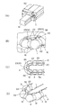
- FIG. 1A and 1B show a rolling element retainer according to a first embodiment of the present invention, in which FIG. 1A is a partial perspective view with a ball removed, FIG. 1B is a partial perspective view with a ball assembled, (C) is a plan view of a partly broken main part, (D) is a front view of a partly broken main part, (E) is a left side view, and (F) shows the relationship between the ball holding part and the wing part. It is a schematic diagram.
- FIG. 2A is a partial perspective view showing a part of an example of the linear motion guide device in which the rolling element retainer of FIG. 1 is incorporated
- FIG. 2B is an enlarged perspective view of the ball circulation path
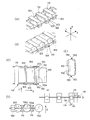
- FIG. 3A and 3B show a rolling element retainer according to a second embodiment of the present invention, in which FIG. 3A is a partial perspective view with a roller removed, FIG. 3B is a partial perspective view with a roller assembled, and FIG. (D) is a partially broken enlarged front view, (E) is a left side view, and (F) is a schematic diagram showing the relationship between the ball holding part and the wing part.
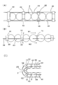
- 4A and 4B show a modification of the rolling element retainer according to the first embodiment of the present invention.
- FIG. 4A is a plan view of a partly broken main part
- FIG. 4B is a front view of a partly broken main part
- FIG. ) Is a partial cross-sectional view when the direction is changed.
- FIG. 1 shows a rolling element retainer according to a first embodiment of the present invention.
- the rolling element retainer 1 is a ball retainer that holds a ball 2.
- a plurality of balls 2 arranged at predetermined intervals are held in series, and a ball holding unit 10 that holds each ball 2 so as to be sandwiched from the front and rear along the ball arrangement direction, and the ball holding unit 10 to the ball
- the arrangement direction of the balls 2 can be bent.
- the balls 2 are rotatably held so that the rotation axes of the balls 2 are parallel to each other while being sandwiched between the ball holding portions 10.
- the arrangement direction of the balls is the X axis direction
- the rotation axis direction of the balls 2 is Y
- the direction orthogonal to the axial direction, the X-axis, and the Y-axis will be described as the Z-axis direction.
- the ball holding portions 10 are arranged every other ball and sandwich the balls 2 one by one from the front and rear.
- the structure of the ball holding portion 10 is a flat cylindrical member having a diameter smaller than the ball diameter, and holding recesses 10a for slidably holding the ball 2 are provided on both end faces thereof.
- the holding recess 10a is formed in a spherical shape into which the ball crown portion of the ball 2 enters.
- the shape of the ball holding portion 10 is not limited to a cylindrical shape.
- the width of the wing portion 22 in the X-axis direction is set to be the same as the width of the ball holding portion 10 in the X-axis direction in the illustrated example, but as schematically shown in FIG. Further, it is preferable that the width A1 of the wing portion 22 in the X-axis direction is set to be equal to or smaller than the width A0 of the ball holding portion 10 in the X-axis direction. Further, the wing portion 22 has a thin plate shape, and as shown in FIG. 1F, the thickness B1 in the Z-axis direction (the direction perpendicular to the ball arrangement direction and the ball rotation axis direction) is Z-axis of the ball holding portion 10. It is smaller than the thickness B0 in the direction.
- the thickness t of the connecting portion 23 in the Z-axis direction is smaller than the thickness B1 of the wing portion 22 in the Z-axis direction. Further, the position of the wing portion 22 in the Z-axis direction is deviated by a predetermined amount with respect to the center of the ball, and the deviated direction is on the inner peripheral side when the direction is changed.
- the connecting portion 23 is composed of a linear member 30 that is a resin material and is a stretched material, and is integrally formed with the ball holding portion 10 and the wing portion 22.
- the linear member 30 extends over the entire length of the rolling element retainer 1 along the arrangement direction X of the balls 2.
- a portion in the middle of the linear member 30 is integrally fixed in a state of penetrating each wing portion 22, and a portion partially exposed between the wing portions 22 is configured as a connecting portion 23.
- the cross-sectional shape of the linear member 30 is preferably a circular shape.
- the cross-sectional shape is not limited to a perfect circle or ellipse, but includes a shape close to a circle.
- the linear member 30 is integrally formed with the ball holding portion 10 and the wing portion 22 by insert molding.
- resin materials that can be injection-molded for example, various resin materials such as polyester, nylon, polyolefin, acrylic, and fluororesin can be used.
- an oil-free linear motion guide device can be realized by using an oil-containing resin.
- the linear member 30 is a resin thread, and is stretched to orient the molecular chain. By extending
- the structure of the fiber and the spinning structure There is no particular limitation on the structure of the fiber and the spinning structure.
- the material of the linear member 30 is not specifically limited, The material which does not swell with respect to the liquid agent of use environments, such as a coolant, for example, a carbon fiber, a fluororesin fiber, etc. is suitable. In this way, it is not necessary to consider the elongation allowance due to the swelling of the rolling element retainer, and when installing in the circulation path, the gap between both ends of the rolling element retainer can be made as small as possible. You can increase the number.
- a heat-resistant material such as carbon fiber may be selected, and it can be used even in an environment at a high temperature.
- the linear member 30 may be made of the same resin as the ball holding unit 10 and the wing unit 22. If the same resin is used, the adhesiveness between the linear member 30 and the wing part 22 is good and can be firmly fixed.
- the linear member 30 glass fiber, a metal wire, etc. other than a resin thread
- one linear member 30 is arranged on each side of the ball row, but a plurality of linear members 30 may be arranged.
- the linear member 30 is not limited to a thread-like form, and includes a belt-like form.
- the linear member 30 and the wing part 22 are being fixed, it does not need to be fixed and the contact part of the linear member 30 and the wing part 22 may be relatively movable. .
- FIG. 2A is a partially broken partial perspective view showing an example of a linear motion guide device as an infinite circulation linear motion device in which the rolling element retainer of FIG. 1 is incorporated
- FIG. 2B is an enlarged perspective view of a ball circulation path
- (C) is a fragmentary sectional view of a direction change path
- (D) is a fragmentary perspective view of the rolling element retainer at the time of a direction change.
- the linear motion guide device 50 includes a track rail 51 and a moving block 52 that is slidably assembled to the track rail 51 via a large number of balls 2.
- the ball 2 is held by the rolling element retainer 1 and is incorporated into a ball circulation path 53 that is a rolling element circulation path formed in the moving block 52.
- the ball circulation path 53 includes a load ball path 54 that extends linearly, a no-load ball path 55 that extends in parallel with the load ball path 54, and a direction change path that connects both ends of the load ball path 54 and the no-load ball path 55. 56.
- the moving block 52 moves to one side, the ball 2 moves while rolling in the moving direction of the moving block 52 in the load ball path 54, and the ball 2 moves from the no-load ball path 55 to the load ball path 54 through the direction change path 56. Moving. At the same time, it is pushed out to the unloaded ball passage 55 through the opposite direction change passage 56 and circulates and moves through the ball circulation passage 53 while being held at a constant interval by the ball holding portion 10 of the rolling element retainer 1.
- the connecting portion 23 between the wing portions 22 is repeatedly bent.
- the connecting portion 23 exposed between the wing portions 22 is long and easily bent. Therefore, the bending stress acting on the connecting portion 23 is reduced as much as possible, the fatigue strength is increased, and the durability is improved.
- the width of the wing portion 22 in the X-axis direction is smaller than the width of the ball holding portion 10 in the X-axis direction, as shown in FIG. Bending stress is reduced.
- the bending stress acting on the connecting portion 23 increases as the radius of curvature of the direction change path 56 decreases and the thickness t of the connecting portion 23 increases.
- the wing part 22 is made smaller than the ball holding part 10 and the connecting part 23 is made as long as possible, and the curvature of the connecting part 23 when reaching the direction change path 56 is made as much as possible. As a result, the bending stress is reduced. Assuming the curvature radius of the connecting portion 23, if the connecting portion 23 is short, the curvature radius becomes smaller than the curvature radius of the direction change path 23. If the wing portion 22 is made as small as the ball holding portion 10 as in the present invention, the curvature radius of the curved connecting portion 23 can be gradually reduced to a size close to the curvature radius of the direction change path 56.
- the thickness t of the connecting portion 23 in the Z-axis direction is also smaller than the thickness of the wing portion 22 in the Z-axis direction, the bending rigidity itself is small and the bending stress can be further reduced. Furthermore, since the cross-sectional shape of the connecting portion 23 is circular, even if the bending direction of the connecting portion 23 varies due to the inclination of the wing portion 22 or the like during the direction change, the bending stress is uniform. In particular, in the case where the linear member 30 itself constituting the connecting portion 23 is a yarn obtained by spinning a thin fiber, the bending stress is dispersed in each fiber, so that it is very small.
- the length of the connecting portion 23 is a straight line between the wing portions 22 of the ball holding portion 10 in a straight path so that a minute gap is formed between the ball 2 and the holding concave portion 10a of the ball holding portion 10.
- the length of the connecting portion 23 may be longer than the linear distance between the wing portions 22 of the ball holding portion 10 in the straight path, and the slack in the direction change path may be increased. Good.
- FIG. 4 shows a modification of the first embodiment.
- the ball holding portions 10 are arranged in every two balls, and two balls 2 are sandwiched from the front and the back by the ball holding portions 10. Even when the two balls 2 are sandwiched in this way, when they are on a straight line, as shown in FIG. 4B, the interval W1 between the adjacent ball holding portions 10 is 2 in the contact state. Since it is smaller than the interval W2 between the two balls, the ball 2 does not fall off. When there are three balls 2, the balls fall off, so it is preferable to place every two balls.
- the length of the connecting portion 23 between the ball holding portions 20 is increased, and the amount of slack in the connecting portion 23 in the direction change path 56 is increased accordingly. Is increased, the bending stress can be further reduced.
- the position of the ball holding portion 10 is determined by the ball 2 and guided all around, so that the ball holding portion 10 and the linear member 30 are connected to the loaded ball passage 54, the no-load ball passage. 55 and the direction change path 56 move without contacting the passage walls.
- the ball holding portion 10 may be configured such that a portion where every two balls are arranged and a portion where every other ball is arranged are mixed.
- FIG. 3 shows a rolling element retainer according to Embodiment 2 of the present invention.
- This rolling element retainer 100 is a type of roller retainer that holds a roller 102. That is, a plurality of rollers 102 arranged at a predetermined interval are held in series, a roller holding unit 110 that holds each roller 102 so as to be sandwiched from the front and rear along the roller arrangement direction, and the roller holding unit 110 to the roller.
- the arrangement direction of the balls 2 can be bent.
- the roller 102 is rotatably held so that the rotation axes of the roller 102 are parallel to each other while being sandwiched between the roller holding portions 110.
- the arrangement direction of the rollers 102 is the X axis direction
- the rotation axis direction of the rollers 102 is the Y axis.
- a direction orthogonal to the axial direction, the X-axis, and the Y-axis is taken as a Z-axis direction.
- the roller holder 110 is a rectangular parallelepiped block smaller than the roller diameter, and is provided with holding recesses 110a for slidably holding the rollers 102 on both front and rear sides in the arrangement direction.
- the holding recess 110a is formed in an arcuate surface shape into which the arc portion of the roller 102 enters.
- the shape of the roller holding portion 110 is not limited to a rectangular parallelepiped shape.
- the width of the wing portion 122 in the X-axis direction is set to the same width as the width of the ball holding portion 10 in the X-axis direction in the illustrated example, but as schematically shown in FIG.
- the width A1 ′ in the X-axis direction of the wing part 122 is preferably set to be equal to or smaller than the width A0 ′ in the X-axis direction of the ball holding part 10.
- the wing part 122 has a thin plate shape, and as shown in FIG. 1 (F), the thickness B1 ′ in the Z-axis direction (the direction perpendicular to the roller arrangement direction and the roller rotation axis direction) is Z of the roller holding part 110.
- the thickness of the connecting portion 123 in the Z-axis direction is smaller than the thickness of the wing portion 122 in the Z-axis direction.
- the position of the wing portion 122 in the Z-axis direction substantially coincides with the center of the roller 102. Of course, it may be shifted as in the first embodiment.
- the connecting portion 123 is composed of a linear member 130 that is a resin material and is a stretched material, and is integrally formed with the roller holding portion 110 and the wing portion 122.
- the linear member 130 extends over the entire length of the rolling element retainer 101 along the arrangement direction X of the rollers 102.
- An intermediate portion of the linear member 130 is integrally fixed in a state of penetrating each wing portion 122, and a portion that is partially exposed between the wing portions 122 is configured as a connecting portion 123.
- the roller holding part 110 and the wing part 122 are molded by injection molding, and the linear member 130 is integrally molded by insert molding together with the roller holding part 110 and the wing part 122.
- the materials of the roller holding part 110 and the wing part 122 and the linear member 130 are the same as those in the first embodiment.
- roller circulation path of the linear motion guide device is the same as that of the ball circulation path shown in FIG. Does not deform.
- the roller holding portions 210 are arranged every two rollers, and the rollers 102 are moved back and forth by the roller holding portions 210 two by two. It can be set as the structure pinched
- Rolling element retainer for balls
- 2 balls rolling elements
- Ball circulation path 56
- Direction change path 101
- Rolling body retainer for rollers
- rollers 102
- Roller (rolling element) A0, A0 ′ Ball, roller holding portion X-axis width A1, A1 ′ wing portion X-axis width B0, B0 ′ Ball, roller holding portion Z-axis thickness B1, B1 ′ wing portion Z Axial thickness
Landscapes
- Engineering & Computer Science (AREA)
- General Engineering & Computer Science (AREA)
- Mechanical Engineering (AREA)
- Bearings For Parts Moving Linearly (AREA)
- Rolling Contact Bearings (AREA)
Abstract
連結部の外表面に作用する曲げ応力を可及的に小さくして、耐久性の高い転動体リテーナ及びこれを用いた無限循環式直線運動装置を提供する。 所定間隔で配列される複数のボール2を一連に保持するもので、各ボール2をボール配列方向に沿って前後から挟むように保持するボール保持部10と、ボール保持部10からボール配列方向に対して直交する方向に突出するウィング部22と、ウィング部22間を連結する可撓性の連結部23と、を備え、連結部23の変形によって、ボール保持部10によってボール保持した状態でボール2の配列方向を曲げることが可能となっている転動体リテーナにおいて、ウィング部22のボール配列方向の幅A1を、ボール保持部10のボール配列方向の幅A0以下としたことを特徴とする。
Description
本発明は、たとえば直動案内装置やボールスプライン、ボールねじ等の各種転がり案内装置に用いられる転動体リテーナ及びこれを用いた無限循環式直線運動装置に関する。
従来のこの種の転動体リテーナとして、本出願人は既に特許文献1に記載のような転動体リテーナを提案している。
すなわち、所定間隔で配列される複数の転動体を一連に保持するもので、各転動体を転動体の配列方向に沿って前後から挟むように保持する転動体保持部と、転動体保持部を連結する連結部とを有し、連結部に線状部材が一体的に埋設されている。
このように線状部材を埋設することによって、引っ張り強度が高まり、耐久性向上を図ることができている。
すなわち、所定間隔で配列される複数の転動体を一連に保持するもので、各転動体を転動体の配列方向に沿って前後から挟むように保持する転動体保持部と、転動体保持部を連結する連結部とを有し、連結部に線状部材が一体的に埋設されている。
このように線状部材を埋設することによって、引っ張り強度が高まり、耐久性向上を図ることができている。
本発明は、上記したような転動体リテーナのさらなる改良を図るべくなされたもので、その目的とするところは、連結部の外表面に作用する曲げ応力を可及的に小さくして、耐久性をより一層向上させ得る転動体リテーナ及び無限循環式直線運動装置を提供することにある。
上記目的を達成するために、本発明は、所定間隔で配列される複数の転動体を一連に保持するもので、転動体を転動体の配列方向に沿って前後から挟むように保持する転動体保持部と、該転動体保持部から転動体配列方向に対して直交する方向に突出するウィング部と、該ウィング部間を連結する可撓性の連結部と、を備え、該連結部の変形によって、転動体保持部によって保持した状態で転動体の配列方向を曲げることが可能となっている転動体リテーナにおいて、前記ウィング部の転動体配列方向の幅を、転動体保持部の転動体配列方向の幅以下としたことを特徴とする。
連結部の転動体配列方向に対して直交する方向の厚みは、ウィング部の転動体配列方向と直交方向の厚みよりも小さくすることが好適である。
連結部の断面形状は円形状であることが好ましい。円形状は、真円だけでなく、楕円形状なども含まれる。また、連結部は樹脂材で延伸材であることが好ましく、さらに、連結部は、転動体保持部及びウィング部と一体的に成形されていることが好適である。
本発明は、転動体保持部が転動体一つ置きに配置されているだけでなく、転動体保持部が転動体二つ置きに配置され、転動体保持部によって転動体を二つずつ前後から挟むような構成となっていてもよい。
また、本発明の無限循環式直線運動装置は、転動体循環路に上記転動体リテーナが組み込まれている。
連結部の転動体配列方向に対して直交する方向の厚みは、ウィング部の転動体配列方向と直交方向の厚みよりも小さくすることが好適である。
連結部の断面形状は円形状であることが好ましい。円形状は、真円だけでなく、楕円形状なども含まれる。また、連結部は樹脂材で延伸材であることが好ましく、さらに、連結部は、転動体保持部及びウィング部と一体的に成形されていることが好適である。
本発明は、転動体保持部が転動体一つ置きに配置されているだけでなく、転動体保持部が転動体二つ置きに配置され、転動体保持部によって転動体を二つずつ前後から挟むような構成となっていてもよい。
また、本発明の無限循環式直線運動装置は、転動体循環路に上記転動体リテーナが組み込まれている。
本発明によれば、ウィング部間に可撓性の連結部を設けることにより、方向転換時に曲げ変形しやすくし、さらに、ウィング部の転動体配列方向の幅を転動体保持部の幅以下とすることで、露出する連結部が長く撓みやすくなり、連結部に作用する曲げ応力を可及的に小さくすることができ、耐疲労強度を高めることができる。
以下にこの発明を実施するための最良の形態を、図示の実施の形態に基づいて詳細に説明する。
実施例1
図1は、本発明の実施例1に係る転動体リテーナを示している。
この転動体リテーナ1は、ボール2を保持するボールリテーナである。すなわち、所定間隔で配列される複数のボール2を一連に保持するもので、各ボール2をボールの配列方向に沿って前後から挟むように保持するボール保持部10と、ボール保持部10からボール配列方向に対して直交する方向に突出するウィング部22と、ウィング部22間を連結する可撓性の連結部23と、を備え、連結部23の変形によって、ボール保持部10によって保持した状態でボール2の配列方向を曲げることが可能となっている。
実施例1
図1は、本発明の実施例1に係る転動体リテーナを示している。
この転動体リテーナ1は、ボール2を保持するボールリテーナである。すなわち、所定間隔で配列される複数のボール2を一連に保持するもので、各ボール2をボールの配列方向に沿って前後から挟むように保持するボール保持部10と、ボール保持部10からボール配列方向に対して直交する方向に突出するウィング部22と、ウィング部22間を連結する可撓性の連結部23と、を備え、連結部23の変形によって、ボール保持部10によって保持した状態でボール2の配列方向を曲げることが可能となっている。
ボール2は、各ボール保持部10に挟まれた状態で、各ボール2の回転軸が互いに平行となるように回転自在に保持される。
ここで、以下の説明では、図1に示すように、互いに直交するX軸、Y軸、Z軸の直交座標を想定し、ボールの配列方向をX軸方向、ボール2の回転軸方向をY軸方向、X軸及びY軸と直交する方向をZ軸方向として説明する。
ボール保持部10は、ボール一つ置きに配置され、ボール2を一つずつ前後から挟む構成となっている。ボール保持部10の構造は、ボール径より小径の扁平な円筒状部材で、その両端面にボール2を摺動自在に保持するための保持凹部10aが設けられている。この保持凹部10aはボール2の球冠部が入り込む球面形状に成形されている。もっとも、ボール保持部10の形状としては、円筒形状に限定されるものではない。
ここで、以下の説明では、図1に示すように、互いに直交するX軸、Y軸、Z軸の直交座標を想定し、ボールの配列方向をX軸方向、ボール2の回転軸方向をY軸方向、X軸及びY軸と直交する方向をZ軸方向として説明する。
ボール保持部10は、ボール一つ置きに配置され、ボール2を一つずつ前後から挟む構成となっている。ボール保持部10の構造は、ボール径より小径の扁平な円筒状部材で、その両端面にボール2を摺動自在に保持するための保持凹部10aが設けられている。この保持凹部10aはボール2の球冠部が入り込む球面形状に成形されている。もっとも、ボール保持部10の形状としては、円筒形状に限定されるものではない。
ウィング部22のX軸方向(ボール配列方向)の幅は、図示例ではボール保持部10のX軸方向の幅と同一幅に設定されているが、図1(F)に模式的に示すように、ウィング部22のX軸方向の幅A1がボール保持部10のX軸方向の幅A0以下に設定することが好適である。
また、ウィング部22は薄板形状で、図1(F)に示すように、Z軸方向(ボール配列方向及びボールの回転軸方向と直交する方向)の厚みB1は、ボール保持部10のZ軸方向の厚みB0よりも小さい。また、連結部23のZ軸方向の厚みtは、ウィング部22のZ軸方向の厚みB1よりも小さくなっている。
また、このウィング部22の、Z軸方向の位置は、ボール中心に対し所定量偏移しており、偏移した方が方向転換時の内周側となる。
また、ウィング部22は薄板形状で、図1(F)に示すように、Z軸方向(ボール配列方向及びボールの回転軸方向と直交する方向)の厚みB1は、ボール保持部10のZ軸方向の厚みB0よりも小さい。また、連結部23のZ軸方向の厚みtは、ウィング部22のZ軸方向の厚みB1よりも小さくなっている。
また、このウィング部22の、Z軸方向の位置は、ボール中心に対し所定量偏移しており、偏移した方が方向転換時の内周側となる。
連結部23は、樹脂材で延伸材である線状部材30によって構成され、ボール保持部10及びウィング部22と一体的に成形されている。線状部材30は、ボール2の配列方向Xに沿って転動体リテーナ1の全長にわたって延びている。この線状部材30の途中の部分が、各ウィング部22を貫通する状態で一体的に固定され、ウィング部22間に部分的に露出した部分が連結部23として構成される。
線状部材30の断面形状は円形状であることが好適である。断面形状としては、真円、楕円に限らず、円形に近い形状についても含むものとする。
線状部材30の断面形状は円形状であることが好適である。断面形状としては、真円、楕円に限らず、円形に近い形状についても含むものとする。
上記線状部材30は、ボール保持部10及びウィング部22と共にインサート成形によって一体的に成形される。
ボール保持部10及びウィング部22については、射出成形可能な樹脂材、たとえば、ポリエステル系、ナイロン系、ポリオレフィン系、アクリル系、フッ素樹脂系などの各種樹脂材を用いることができる。特に、含油樹脂によって構成すれば、無給油タイプの直線運動案内装置が実現できる。
ボール保持部10及びウィング部22については、射出成形可能な樹脂材、たとえば、ポリエステル系、ナイロン系、ポリオレフィン系、アクリル系、フッ素樹脂系などの各種樹脂材を用いることができる。特に、含油樹脂によって構成すれば、無給油タイプの直線運動案内装置が実現できる。
一方、線状部材30は樹脂糸であり、延伸して分子鎖を配向させている。延伸することで、各分子間の密度が高くなり、引っ張り強度が高くなる。繊維の構造、紡糸構造については特に限定されない。
線状部材30の材料は特に限定されないが、クーラント等の使用環境の液剤に対して膨潤しない材料、たとえば炭素繊維やフッ素樹脂繊維等が好適である。このようにすれば、転動体リテーナの膨潤による伸び代を考慮する必要がなく、循環路に装着する場合に、転動体リテーナの両端の隙間を可及的に小さくでき、その分、装着できるボール数を増やすことができる。また、炭素繊維等の耐熱性の材料を選択してもよく、高温化での環境でも使用可能となる。
線状部材30と、ボール保持部10及びウィング部22を、別体構成とすることで、樹脂材の選択範囲が広がり、耐久性のある膨潤しないリテーナを実現できる。
線状部材30の材料は特に限定されないが、クーラント等の使用環境の液剤に対して膨潤しない材料、たとえば炭素繊維やフッ素樹脂繊維等が好適である。このようにすれば、転動体リテーナの膨潤による伸び代を考慮する必要がなく、循環路に装着する場合に、転動体リテーナの両端の隙間を可及的に小さくでき、その分、装着できるボール数を増やすことができる。また、炭素繊維等の耐熱性の材料を選択してもよく、高温化での環境でも使用可能となる。
線状部材30と、ボール保持部10及びウィング部22を、別体構成とすることで、樹脂材の選択範囲が広がり、耐久性のある膨潤しないリテーナを実現できる。
もっとも、線状部材30を、ボール保持部10及びウィング部22と同一樹脂によって構成してもよい。同一樹脂とすれば、線状部材30とウィング部22間の接着性がよく、強固に固定することができる。
また、線状部材30としては、樹脂糸のほかに、ガラス繊維や金属製のワイヤー等を用いることもできる。また、図示例では、線状部材30を、ボール列の両側に1本ずつ配置したが、複数本配置してもよい。また、線状部材30は糸状の形態に限定されるものではなく、ベルト状の形態も含まれる。
なお、上記実施例では、線状部材30とウィング部22を固定しているが、固定される必要はなく、線状部材30とウィング部22の接触部が相対移動可能となっていてもよい。
また、線状部材30としては、樹脂糸のほかに、ガラス繊維や金属製のワイヤー等を用いることもできる。また、図示例では、線状部材30を、ボール列の両側に1本ずつ配置したが、複数本配置してもよい。また、線状部材30は糸状の形態に限定されるものではなく、ベルト状の形態も含まれる。
なお、上記実施例では、線状部材30とウィング部22を固定しているが、固定される必要はなく、線状部材30とウィング部22の接触部が相対移動可能となっていてもよい。
図2(A)は、図1の転動体リテーナが組み込まれる無限循環式直線運動装置としての直線運動案内装置の一例を示す一部破断部分斜視図、(B)はボール循環路の拡大斜視図、(C)は方向転換路の部分断面図、(D)は方向転換する際の転動体リテーナの部分斜視図である。
この直線運動案内装置50は、軌道レール51と、軌道レール51に多数のボール2を介して摺動自在に組みつけられる移動ブロック52とから構成される。ボール2は転動体リテーナ1に保持され、移動ブロック52に形成された転動体循環路であるボール循環路53に組み込まれるものである。
この直線運動案内装置50は、軌道レール51と、軌道レール51に多数のボール2を介して摺動自在に組みつけられる移動ブロック52とから構成される。ボール2は転動体リテーナ1に保持され、移動ブロック52に形成された転動体循環路であるボール循環路53に組み込まれるものである。
ボール循環路53は、直線的に延びる負荷ボール通路54と、この負荷ボール通路54と平行に延びる無負荷ボール通路55と、負荷ボール通路54と無負荷ボール通路55の両端を連結する方向転換路56とを有する構成となっている。
移動ブロック52が一方に移動すると、負荷ボール通路54において移動ブロック52の移動方向にボール2が転動しながら移動し、無負荷ボール通路55から方向転換路56を通じてボール2が負荷ボール通路54に移動する。同時に、反対側の方向転換路56を通じて無負荷ボール通路55に押し出され、転動体リテーナ1のボール保持部10によって一定間隔に保持されながらボール循環路53を循環移動する。
移動ブロック52が一方に移動すると、負荷ボール通路54において移動ブロック52の移動方向にボール2が転動しながら移動し、無負荷ボール通路55から方向転換路56を通じてボール2が負荷ボール通路54に移動する。同時に、反対側の方向転換路56を通じて無負荷ボール通路55に押し出され、転動体リテーナ1のボール保持部10によって一定間隔に保持されながらボール循環路53を循環移動する。
ボール2が方向転換路56を通過する度に、ウィング部22間の連結部23が繰り返しベンディングを受けることになる。本実施例では、ウィング部22のX軸方向の幅がボール保持部10と同一幅となっているので、ウィング部22間に露出する連結部23が長く撓みやすい。したがって、連結部23に作用する曲げ応力はを可及的に小さくなり、疲労強度は高まり、耐久性が向上する。
このウィング部22のX軸方向の幅が、図1(F)に示したように、ボール保持部10のX軸方向の幅より小さいほど、連結部23が長くなり、方向転換路56での曲げ応力が小さくなる。
この点を詳細に説明すると、連結部23に作用する曲げ応力は、方向転換路56の曲率半径が小さいほど、かつ連結部23の厚みtが大きいほど大きくなる。逆に、方向転換路56の曲率半径が大きくゆるやかであるほど、かつ連結部23の厚みtが小さいほど小さくなる。そこで、方向転換路56を大きくすることが考えられるが、装置が大型化してしまうので、方向転換路56の大きさは制約される。
方向転換路56の曲率半径を一定とすると、ウィング部22が長く、連結部23があまり露出しない転動体リテーナを使用すると、連結部23が短くなるために、方向転換路56を通過する際の連結部23の曲率が大きくなり、曲げ応力増大につながる。
そこで、本発明では、ウィング部22をボール保持部10より小さくして連結部23を可及的に長くしたもので、方向転換路56に差し掛かった際の連結部23の曲率が可及的に小さくなり、結果として曲げ応力が小さくなる。
連結部23の曲率半径を想定すると、連結部23が短いと、その曲率半径が方向転換路23の曲率半径よりも小さくなってしまう。本発明のように、ウィング部22をボール保持部10程度まで小さくすれば、湾曲した連結部23の曲率半径が方向転換路56の曲率半径に近い大きさまでゆるやかにすることができる。
このウィング部22のX軸方向の幅が、図1(F)に示したように、ボール保持部10のX軸方向の幅より小さいほど、連結部23が長くなり、方向転換路56での曲げ応力が小さくなる。
この点を詳細に説明すると、連結部23に作用する曲げ応力は、方向転換路56の曲率半径が小さいほど、かつ連結部23の厚みtが大きいほど大きくなる。逆に、方向転換路56の曲率半径が大きくゆるやかであるほど、かつ連結部23の厚みtが小さいほど小さくなる。そこで、方向転換路56を大きくすることが考えられるが、装置が大型化してしまうので、方向転換路56の大きさは制約される。
方向転換路56の曲率半径を一定とすると、ウィング部22が長く、連結部23があまり露出しない転動体リテーナを使用すると、連結部23が短くなるために、方向転換路56を通過する際の連結部23の曲率が大きくなり、曲げ応力増大につながる。
そこで、本発明では、ウィング部22をボール保持部10より小さくして連結部23を可及的に長くしたもので、方向転換路56に差し掛かった際の連結部23の曲率が可及的に小さくなり、結果として曲げ応力が小さくなる。
連結部23の曲率半径を想定すると、連結部23が短いと、その曲率半径が方向転換路23の曲率半径よりも小さくなってしまう。本発明のように、ウィング部22をボール保持部10程度まで小さくすれば、湾曲した連結部23の曲率半径が方向転換路56の曲率半径に近い大きさまでゆるやかにすることができる。
また、連結部23のZ軸方向の厚みtも、ウィング部22のZ軸方向の厚みよりも小さいので、曲げ剛性自体が小さく、より一層、曲げ応力を小さくすることができる。さらに、連結部23の断面形状は円形状なので、方向転換時にウィング部22の傾き等によって連結部23の曲がり方向がばらついても、曲げ応力は均等である。とくに、連結部23を構成する線状部材30自体は細い繊維を紡糸した糸の場合には、曲げ応力は各繊維に分散されるので、ごく小さい。
この実施例では、連結部23の長さを、ボール2とボール保持部10の保持凹部10aとの間に微小な隙間ができる程度に、直線路におけるボール保持部10のウィング部22間の直線距離に合わせているが、場合によっては、連結部23の長さを直線路におけるボール保持部10のウィング部22間の直線距離よりも長くして、方向転換路におけるたるみをより大きくしてもよい。
この実施例では、連結部23の長さを、ボール2とボール保持部10の保持凹部10aとの間に微小な隙間ができる程度に、直線路におけるボール保持部10のウィング部22間の直線距離に合わせているが、場合によっては、連結部23の長さを直線路におけるボール保持部10のウィング部22間の直線距離よりも長くして、方向転換路におけるたるみをより大きくしてもよい。
図4は、上記実施例1の変形例を示している。
この変形例は、ボール保持部10をボール二つ置きに配置し、ボール保持部10によってボール2を二つずつ前後から挟むような構成としたものである。
このようにボール2を二つずつ挟むような構成としても、直線上にある場合には、図4(B)に示すように、隣り合うボール保持部10間の間隔W1が、接触状態の2つのボールの間隔W2よりも小さいので、ボール2は脱落しない。このボール2が3つの場合にはボールが脱落してしまうので、二つ置きまでが好ましい。
この変形例は、ボール保持部10をボール二つ置きに配置し、ボール保持部10によってボール2を二つずつ前後から挟むような構成としたものである。
このようにボール2を二つずつ挟むような構成としても、直線上にある場合には、図4(B)に示すように、隣り合うボール保持部10間の間隔W1が、接触状態の2つのボールの間隔W2よりも小さいので、ボール2は脱落しない。このボール2が3つの場合にはボールが脱落してしまうので、二つ置きまでが好ましい。
ボール2を二つずつ保持することにより、図4(C)に示すように、ボール保持部20間の連結部23の長さが長くなり、その分だけ方向転換路56における連結部23のたるみが大きくなるので、曲げ応力をより小さくすることがすることができる。
ボール循環路53に組み付けた場合、ボール2によってボール保持部10の位置が決まり、全周的に案内されるので、ボール保持部10や線状部材30が、負荷ボール通路54、無負荷ボール通路55及び方向転換路56の通路壁に接触せずに移動する。
なお、場合によっては、一つの転動体リテーナにおいて、ボール保持部10を、ボール二つ置きの配置した部分と、ボール一つ置きに配置した部分が混在するような構成となっていてもよい。
ボール循環路53に組み付けた場合、ボール2によってボール保持部10の位置が決まり、全周的に案内されるので、ボール保持部10や線状部材30が、負荷ボール通路54、無負荷ボール通路55及び方向転換路56の通路壁に接触せずに移動する。
なお、場合によっては、一つの転動体リテーナにおいて、ボール保持部10を、ボール二つ置きの配置した部分と、ボール一つ置きに配置した部分が混在するような構成となっていてもよい。
実施例2
次に、本発明の実施例2について説明する。
図3は、本発明の実施例2に係る転動体リテーナを示している。
この転動体リテーナ100は、ローラ102を保持するローラリテーナのタイプである。
すなわち、所定間隔で配列される複数のローラ102を一連に保持するもので、各ローラ102をローラの配列方向に沿って前後から挟むように保持するローラ保持部110と、ローラ保持部110からローラ配列方向に対して直交する方向に突出するウィング部122と、ウィング部122間を連結する可撓性の連結部123と、を備え、連結部123の変形によって、ローラ保持部110によって保持した状態でボール2の配列方向を曲げることが可能となっている。
次に、本発明の実施例2について説明する。
図3は、本発明の実施例2に係る転動体リテーナを示している。
この転動体リテーナ100は、ローラ102を保持するローラリテーナのタイプである。
すなわち、所定間隔で配列される複数のローラ102を一連に保持するもので、各ローラ102をローラの配列方向に沿って前後から挟むように保持するローラ保持部110と、ローラ保持部110からローラ配列方向に対して直交する方向に突出するウィング部122と、ウィング部122間を連結する可撓性の連結部123と、を備え、連結部123の変形によって、ローラ保持部110によって保持した状態でボール2の配列方向を曲げることが可能となっている。
ローラ102は、ローラ保持部110に挟まれた状態で、ローラ102の回転軸が互いに平行となるように回転自在に保持される。この実施例2についても、図3に示すように、互いに直交するX軸、Y軸、Z軸の直交座標を想定し、ローラ102の配列方向をX軸方向、ローラ102の回転軸方向をY軸方向、X軸及びY軸と直交する方向をZ軸方向とする。
ローラ保持部110は、ローラ径より小さい直方体形状のブロック体で、その配列方向前後両面にローラ102を摺動自在に保持するための保持凹部110aが設けられている。この保持凹部110aはローラ102の円弧部が入り込む円弧面形状に成形されている。もっとも、ローラ保持部110の形状としては、直方体形状に限定されるものではない。
ウィング部122のX軸方向(ローラ配列方向)の幅は、図示例ではボール保持部10のX軸方向の幅と同一幅に設定されているが、図3(F)に模式的に示すように、ウィング部122のX軸方向の幅A1′はボール保持部10のX軸方向の幅A0′以下に設定されることが好適である。
一方、ウィング部122は薄板形状で、図1(F)に示すように、Z軸方向(ローラ配列方向及びローラの回転軸方向と直交する方向)の厚みB1′は、ローラ保持部110のZ軸方向の厚みB0′よりも小さい。また、連結部123のZ軸方向の厚みは、ウィング部122のZ軸方向の厚みよりも小さくなっている。
また、この実施例2では、ウィング部122のZ軸方向の位置は、ローラ102の中心とほぼ一致している。もちろん、実施例1と同様にずらしてもよい。
一方、ウィング部122は薄板形状で、図1(F)に示すように、Z軸方向(ローラ配列方向及びローラの回転軸方向と直交する方向)の厚みB1′は、ローラ保持部110のZ軸方向の厚みB0′よりも小さい。また、連結部123のZ軸方向の厚みは、ウィング部122のZ軸方向の厚みよりも小さくなっている。
また、この実施例2では、ウィング部122のZ軸方向の位置は、ローラ102の中心とほぼ一致している。もちろん、実施例1と同様にずらしてもよい。
連結部123は、樹脂材で延伸材である線状部材130によって構成され、ローラ保持部110及びウィング部122と一体的に成形されている。線状部材130は、ローラ102の配列方向Xに沿って転動体リテーナ101の全長にわたって延びている。この線状部材130の途中の部分が、各ウィング部122を貫通する状態で一体的に固定され、ウィング部122間に部分的に露出した部分が連結部123として構成される。
上記ローラ保持部110及びウィング部122が射出成形によって成型され、線状部材130が、ローラ保持部110及びウィング部122と共にインサート成形によって一体的に成形される。
このローラ保持部110及びウィング部122と、線状部材130の材料については、実施例1と同様である。
このローラ保持部110及びウィング部122と、線状部材130の材料については、実施例1と同様である。
また、直線運動案内装置のローラ循環路の構成についても、図2に示したボール循環路の場合と同一であり、転動体リテーナは繰り返しベンディングを受けるものの、連結部123において大きく撓み、ウィング部122は変形しない。
特に、ローラ102の場合には、ローラ102は、移動方向前後に位置するローラ保持部110によってローラ102の回転軸間が平行に保持されるので、スキューの発生が防止される。
この実施例2の転動体リテーナについても、図4に示した実施例1の変形と同様に、 ローラ保持部210がローラ二つ置きに配置され、ローラ保持部210によってローラ102を二つずつ前後から挟むような構成とすることができる。
また、上記各実施例に記載されている構成部品の材質、形状、その相対配置などは、特に特定的な記載がない限りは、この発明の範囲をそれらのみに限定する趣旨のものではない。
この実施例2の転動体リテーナについても、図4に示した実施例1の変形と同様に、 ローラ保持部210がローラ二つ置きに配置され、ローラ保持部210によってローラ102を二つずつ前後から挟むような構成とすることができる。
また、上記各実施例に記載されている構成部品の材質、形状、その相対配置などは、特に特定的な記載がない限りは、この発明の範囲をそれらのみに限定する趣旨のものではない。
1 転動体リテーナ(ボール用)
2 ボール(転動体)
10,110 ボール保持部
11 線状部材
22,122 ウィング部
23,123 連結部
30,130 線状部材
53 ボール循環路
56 方向転換路
101 転動体リテーナ(ローラ用)
102 ローラ(転動体)
A0、A0′ ボール、ローラ保持部のX軸方向の幅
A1、A1′ ウィング部のX軸方向の幅
B0、B0′ ボール、ローラ保持部のZ軸方向の厚み
B1、B1′ ウィング部のZ軸方向の厚み
2 ボール(転動体)
10,110 ボール保持部
11 線状部材
22,122 ウィング部
23,123 連結部
30,130 線状部材
53 ボール循環路
56 方向転換路
101 転動体リテーナ(ローラ用)
102 ローラ(転動体)
A0、A0′ ボール、ローラ保持部のX軸方向の幅
A1、A1′ ウィング部のX軸方向の幅
B0、B0′ ボール、ローラ保持部のZ軸方向の厚み
B1、B1′ ウィング部のZ軸方向の厚み
Claims (8)
- 所定間隔で配列される複数の転動体を一連に保持するもので、前記転動体を転動体の配列方向に沿って前後から挟むように保持する転動体保持部と、該転動体保持部から転動体配列方向に対して直交する方向に突出するウィング部と、該ウィング部間を連結する可撓性の連結部と、を備え、該連結部の変形によって、転動体保持部によって保持した状態で転動体の配列方向を曲げることが可能となっている転動体リテーナにおいて、
前記ウィング部の転動体配列方向の幅を、転動体保持部の転動体配列方向の幅以下としたことを特徴とする転動体リテーナ。 - 連結部の転動体配列方向に対して直交する方向の厚みは、ウィング部の転動体配列方向と直交方向の厚みよりも小さいことを特徴とする請求項1に記載の転動体リテーナ。
- 連結部の断面形状は円形状である請求項1又は2に記載の転動体リテーナ。
- 連結部は、樹脂材で延伸材である請求項1乃至3のいずれかの項に記載の転動体リテーナ。
- 連結部は、転動体保持部及びウィング部と一体的に成形されている請求項1乃至4のいずれかの項に記載の転動体リテーナ。
- 転動体保持部が、転動体一つ置きに配置されている請求項1乃至5のいずれかの項に記載の転動体リテーナ。
- 転動体保持部が、転動体二つ置きに配置されている請求項1乃至5のいずれかの項に記載の転動体リテーナ。
- 転動体循環路に請求項1乃至7のいずれかの項に記載の転動体リテーナが組み込まれた無限循環式直線運動装置。
Priority Applications (1)
| Application Number | Priority Date | Filing Date | Title |
|---|---|---|---|
| JP2010544124A JPWO2010074155A1 (ja) | 2008-12-26 | 2009-12-24 | 転動体リテーナ及びこれを用いた無限循環式直線運動装置 |
Applications Claiming Priority (2)
| Application Number | Priority Date | Filing Date | Title |
|---|---|---|---|
| JP2008333902 | 2008-12-26 | ||
| JP2008-333902 | 2008-12-26 |
Publications (1)
| Publication Number | Publication Date |
|---|---|
| WO2010074155A1 true WO2010074155A1 (ja) | 2010-07-01 |
Family
ID=42287762
Family Applications (1)
| Application Number | Title | Priority Date | Filing Date |
|---|---|---|---|
| PCT/JP2009/071457 Ceased WO2010074155A1 (ja) | 2008-12-26 | 2009-12-24 | 転動体リテーナ及びこれを用いた無限循環式直線運動装置 |
Country Status (3)
| Country | Link |
|---|---|
| JP (1) | JPWO2010074155A1 (ja) |
| TW (1) | TW201030251A (ja) |
| WO (1) | WO2010074155A1 (ja) |
Cited By (3)
| Publication number | Priority date | Publication date | Assignee | Title |
|---|---|---|---|---|
| WO2012146549A1 (de) * | 2011-04-29 | 2012-11-01 | Aktiebolaget Skf | Gliederkettenkäfig |
| DE102011089078A1 (de) * | 2011-12-19 | 2013-06-20 | Aktiebolaget Skf | Lagerkäfigsegment, Lagerkäfig und Verfahren zur Herstellung desselben |
| WO2017104428A1 (ja) * | 2015-12-15 | 2017-06-22 | Thk株式会社 | 運動案内装置 |
Families Citing this family (1)
| Publication number | Priority date | Publication date | Assignee | Title |
|---|---|---|---|---|
| JP6385384B2 (ja) * | 2016-04-11 | 2018-09-05 | Thk株式会社 | 転がり案内装置 |
Citations (5)
| Publication number | Priority date | Publication date | Assignee | Title |
|---|---|---|---|---|
| JPH09242759A (ja) * | 1996-03-11 | 1997-09-16 | Nippon Seiko Kk | コロ軸受 |
| JPH10110728A (ja) * | 1996-10-04 | 1998-04-28 | Thk Kk | ローラチェイン |
| JPH11247855A (ja) * | 1998-03-04 | 1999-09-14 | Nippon Thompson Co Ltd | 直動転がり案内ユニット |
| JP2004092799A (ja) * | 2002-08-30 | 2004-03-25 | Nsk Ltd | リニアガイド装置 |
| JP2006226308A (ja) * | 2005-02-15 | 2006-08-31 | Jtekt Corp | 円錐ころ軸受用保持器 |
-
2009
- 2009-12-24 JP JP2010544124A patent/JPWO2010074155A1/ja not_active Withdrawn
- 2009-12-24 WO PCT/JP2009/071457 patent/WO2010074155A1/ja not_active Ceased
- 2009-12-25 TW TW098145061A patent/TW201030251A/zh unknown
Patent Citations (5)
| Publication number | Priority date | Publication date | Assignee | Title |
|---|---|---|---|---|
| JPH09242759A (ja) * | 1996-03-11 | 1997-09-16 | Nippon Seiko Kk | コロ軸受 |
| JPH10110728A (ja) * | 1996-10-04 | 1998-04-28 | Thk Kk | ローラチェイン |
| JPH11247855A (ja) * | 1998-03-04 | 1999-09-14 | Nippon Thompson Co Ltd | 直動転がり案内ユニット |
| JP2004092799A (ja) * | 2002-08-30 | 2004-03-25 | Nsk Ltd | リニアガイド装置 |
| JP2006226308A (ja) * | 2005-02-15 | 2006-08-31 | Jtekt Corp | 円錐ころ軸受用保持器 |
Cited By (5)
| Publication number | Priority date | Publication date | Assignee | Title |
|---|---|---|---|---|
| WO2012146549A1 (de) * | 2011-04-29 | 2012-11-01 | Aktiebolaget Skf | Gliederkettenkäfig |
| DE102011089078A1 (de) * | 2011-12-19 | 2013-06-20 | Aktiebolaget Skf | Lagerkäfigsegment, Lagerkäfig und Verfahren zur Herstellung desselben |
| DE102011089078B4 (de) * | 2011-12-19 | 2014-11-27 | Aktiebolaget Skf | Lagerkäfig und Verfahren zur Herstellung desselben |
| WO2017104428A1 (ja) * | 2015-12-15 | 2017-06-22 | Thk株式会社 | 運動案内装置 |
| US10436248B2 (en) | 2015-12-15 | 2019-10-08 | Thk Co., Ltd. | Motion guide device |
Also Published As
| Publication number | Publication date |
|---|---|
| JPWO2010074155A1 (ja) | 2012-06-21 |
| TW201030251A (en) | 2010-08-16 |
Similar Documents
| Publication | Publication Date | Title |
|---|---|---|
| WO1998031945A1 (en) | Ball chain | |
| JPWO2010074155A1 (ja) | 転動体リテーナ及びこれを用いた無限循環式直線運動装置 | |
| KR20130006392A (ko) | 전동 벨트용 풀리 및 벨트 전동 장치 | |
| CN206449110U (zh) | 滑块组件 | |
| CN108779797B (zh) | 滚动导向装置 | |
| US7465092B2 (en) | Ball chain | |
| JP2012217328A (ja) | ケーブル支持部材 | |
| TW201437504A (zh) | 滾動體收容具 | |
| TWI585313B (zh) | Movement guide device | |
| TWI518257B (zh) | Movement guide device | |
| JP2005003195A (ja) | 転動体連結体、及び直線案内装置 | |
| CN211259373U (zh) | 链带式保持器与线性移动装置 | |
| JP2005147353A (ja) | 直動案内装置 | |
| JP2008196659A (ja) | 直動案内装置およびこれに適用される転動体収容ベルト | |
| KR102457930B1 (ko) | 베어링 리테이너 | |
| JP4539574B2 (ja) | 転動体収容ベルトおよび直動案内装置 | |
| JP4609303B2 (ja) | 直動案内装置およびその製造方法 | |
| JP2008285312A (ja) | 平ベルト搬送装置 | |
| JP2008249043A (ja) | 転動体収容ベルトおよび直動案内装置 | |
| JP2008121861A (ja) | 玉収容部材及び直動案内装置 | |
| JP4501862B2 (ja) | 転動体収容ベルトおよび直動案内装置 | |
| JP2008121862A (ja) | 直動案内装置 | |
| JP2008286351A (ja) | 平ベルト用プーリ | |
| JP2520797B2 (ja) | 直線運動案内装置 | |
| JP2008138742A (ja) | 転動体保持スペーサ及びリニアガイド |
Legal Events
| Date | Code | Title | Description |
|---|---|---|---|
| 121 | Ep: the epo has been informed by wipo that ep was designated in this application |
Ref document number: 09834953 Country of ref document: EP Kind code of ref document: A1 |
|
| ENP | Entry into the national phase |
Ref document number: 2010544124 Country of ref document: JP Kind code of ref document: A |
|
| NENP | Non-entry into the national phase |
Ref country code: DE |
|
| 122 | Ep: pct application non-entry in european phase |
Ref document number: 09834953 Country of ref document: EP Kind code of ref document: A1 |