WO2010074147A1 - 攪拌・脱泡装置及び攪拌・脱泡方法 - Google Patents
攪拌・脱泡装置及び攪拌・脱泡方法 Download PDFInfo
- Publication number
- WO2010074147A1 WO2010074147A1 PCT/JP2009/071438 JP2009071438W WO2010074147A1 WO 2010074147 A1 WO2010074147 A1 WO 2010074147A1 JP 2009071438 W JP2009071438 W JP 2009071438W WO 2010074147 A1 WO2010074147 A1 WO 2010074147A1
- Authority
- WO
- WIPO (PCT)
- Prior art keywords
- container
- axis
- revolution
- stirring
- defoaming
- Prior art date
- Legal status (The legal status is an assumption and is not a legal conclusion. Google has not performed a legal analysis and makes no representation as to the accuracy of the status listed.)
- Ceased
Links
Images


Classifications
-
- B—PERFORMING OPERATIONS; TRANSPORTING
- B01—PHYSICAL OR CHEMICAL PROCESSES OR APPARATUS IN GENERAL
- B01D—SEPARATION
- B01D19/00—Degasification of liquids
- B01D19/02—Foam dispersion or prevention
-
- B—PERFORMING OPERATIONS; TRANSPORTING
- B01—PHYSICAL OR CHEMICAL PROCESSES OR APPARATUS IN GENERAL
- B01D—SEPARATION
- B01D19/00—Degasification of liquids
-
- B—PERFORMING OPERATIONS; TRANSPORTING
- B01—PHYSICAL OR CHEMICAL PROCESSES OR APPARATUS IN GENERAL
- B01F—MIXING, e.g. DISSOLVING, EMULSIFYING OR DISPERSING
- B01F29/00—Mixers with rotating receptacles
- B01F29/10—Mixers with rotating receptacles with receptacles rotated about two different axes, e.g. receptacles having planetary motion
-
- B—PERFORMING OPERATIONS; TRANSPORTING
- B01—PHYSICAL OR CHEMICAL PROCESSES OR APPARATUS IN GENERAL
- B01F—MIXING, e.g. DISSOLVING, EMULSIFYING OR DISPERSING
- B01F29/00—Mixers with rotating receptacles
- B01F29/90—Mixers with rotating receptacles with stirrers having planetary motion
Definitions
- the present invention relates to a stirring / defoaming apparatus and a stirring / defoaming method capable of stirring / defoaming an object to be processed contained in a container.
- this kind of agitation / defoaming device is configured to be rotatable around a revolution axis, and is configured to be able to accommodate a workpiece and a table provided with the rotation axis, and is installed on the table and is rotated around the rotation axis. And a container that revolves around the revolution axis of the table, and the rotation axis is inclined at a predetermined angle so as to intersect the revolution axis (the following patents are known) Reference 1).
- Such a stirring / defoaming apparatus can defoam the object to be treated in the container by revolving the container around the revolution axis, and while revolving the container around the revolution axis as a stirring / defoaming method.
- the object to be processed in the container can be stirred and degassed, and various objects to be processed can be stirred in a short time.
- -It can be degassed.
- this invention is made in view of the said improvement point, and it aims at providing the stirring / defoaming apparatus and the stirring / defoaming method which can stir and deaerate the to-be-processed object accommodated in the container reliably. To do.
- the present invention has been made to solve the above-mentioned problems, and the stirring and defoaming apparatus according to the present invention is configured to be rotatable around a revolution axis, and is provided with a table provided with a rotation axis, and a workpiece.
- the container is configured to be capable of being accommodated, and includes a container that can rotate around the rotation axis of the table and revolves around the rotation axis of the table, and the rotation axis is twisted with respect to the rotation axis. It is characterized by that.
- the object to be processed in the container can be degassed by installing the container containing the object to be processed on the table and revolving around the revolution axis. By rotating the container around the rotation axis while revolving, the object to be processed in the container can be stirred and defoamed.
- the centrifugal force due to revolution acting on the workpiece accommodated in the container mainly passes through the rotation axis and is parallel to the revolution axis. Will act in the direction that intersects. Therefore, when the container containing the object to be processed is rotated while revolving, the object to be processed stored in the container is entirely divided by the centrifugal force due to revolution and the centrifugal force due to rotation acting in the direction intersecting the reference plane. It is stirred. Therefore, it is possible to reliably stir and degas the object to be processed accommodated in the container.
- the rotation axis is a twisted position with respect to the revolution axis is a positional relationship in which the rotation axis and the revolution axis are not parallel and do not intersect, that is, the rotation axis and the revolution axis are in the same plane. It means that it is a positional relationship that does not get on.
- At least one end of the container in the central axis direction is closed, the central axis coincides with the rotation axis, and the other end in the central axis direction is closer to the revolution axis than the one end.
- it is preferably installed on the table.
- the stirring and defoaming method according to the present invention revolves the container containing the object to be processed around the revolution axis and rotates around the rotation axis located at a twist position with respect to the revolution axis.
- the object to be treated is agitated and defoamed.
- the rotation axis is in a twisted position with respect to the revolution axis, so that the container containing the object to be processed is revolved.
- the object to be processed contained in the container is agitated as a whole by the centrifugal force due to revolution and the centrifugal force due to rotation acting in the direction intersecting the reference plane, so that the object to be processed is surely obtained.
- stirring and defoaming can be performed.
- FIG. 4C is a schematic front view showing the state of the stirring / defoaming step by the stirring / defoaming apparatus according to the present invention
- FIG. 4D is a sectional view taken along the line QQ of FIG.
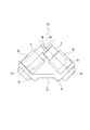
- the schematic plan view which shows other embodiment of the stirring and defoaming apparatus which concerns on this invention.
- the stirring / defoaming apparatus 1 is an apparatus capable of stirring / defoaming an object to be processed made of a plurality of materials.
- a to-be-processed object is a to-be-stirred material which dislikes bubbles, such as a medical material, an electronic component material, and a liquid crystal material, for example.
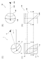
- the agitation / defoaming device 1 is configured to be rotatable about a revolution axis C1, and is configured to be able to accommodate a table 2 provided with a rotation axis C2 and an object to be processed. And a container 3 that can revolve around C2 and revolves around the revolution axis C1 of the table 2.
- the thing of various structures can be employ
- a driving means that includes a revolution motor that rotates the table 2 around the revolution axis C1 and a rotation motor that rotates the container 3 around the revolution axis C2.
- a driving means including a motor that rotates the table 2 around the revolution axis C1 and a transmission means that transmits the driving force of the motor to rotate the container 3 around the rotation axis C2.
- the transmission means can be configured by, for example, a combination of a pulley and a belt or a gear, and can be configured to make revolution and rotation independent by using a cut bearing. Etc., the rotational speed of the rotation can be made variable.
- the table 2 is provided with a revolution axis C1 and a rotation axis C2, and is a rotary table rotatable around the revolution axis C1.
- the table 2 rotates around the revolution axis C1 extending along the thickness direction (vertical direction).
- a possible base portion 21 (revolution direction arrow R1) and a receiving portion 22 (rotation direction arrow R2) provided on the base portion 21 and rotatable about the rotation axis C2 are provided.
- the base portion 21 is configured to be rotatable around a revolution axis C1 provided so as to pass vertically through the central portion of the upper surface, and a part of the peripheral edge portion of the upper surface is an inclined surface 211.
- the inclined surface 211 is a plane inclined by a predetermined angle with respect to the base surface P1, which is a plane orthogonal to the revolution axis C1, and is inclined downward so as to be closer to the revolution axis C1.
- a pair of inclined surfaces 211 are provided so as to be symmetric with respect to the revolution axis C1.
- the receiving portion 22 is formed in a bottomed cylindrical shape, and is configured to be rotatable around the rotation axis C2 with the center axis as the rotation axis C2.
- the receiving portion 22 is provided on the inclined surface 211 so that the rotation axis C2 is perpendicular to the inclined surface 211 of the base portion 21, and is provided in a pair so as to be symmetric with respect to the revolution axis C1. . Therefore, the rotation axis C2 is provided as a pair so as to be symmetric with respect to the revolution axis C1.
- revolution axis C1 and the rotation axis C2 are not parallel and do not cross each other, in other words, are not in the same plane, and are in a so-called torsional position relationship.
- the rotation axis C2 is inclined by a predetermined angle ⁇ with respect to the base plane P1, which is a plane orthogonal to the revolution axis C1, and passes through the rotation axis C2 to the revolution axis C1.
- the distance between the reference plane P2 that is a parallel plane and the revolution axis C1 is set so as not to intersect the revolution axis C1 so that the predetermined distance X is obtained.
- the angle ⁇ of the rotation axis C2 with respect to the base surface P1 can be 10 ° to 80 °, and is 50 ° in this embodiment.
- the separation distance X between the revolution axis C1 and the reference plane P2 (that is, the separation distance between the revolution axis C1 and the rotation axis C2) is equal to the radius of the container 3 or slightly larger than the radius of the container 3. It is a small distance. Therefore, the separation distance between the rotation axes C2 provided symmetrically with respect to the revolution axis C1 is equal to or slightly smaller than the diameter of the container 3.
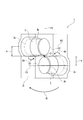
- the container 3 is a cylindrical body in which at least one end 3a in the central axis direction is closed. Specifically, the container 3 is hermetically sealed so that one end 3a in the central axis direction cannot be opened, and the other end 3b can be opened so that an object to be treated can be taken out. It is a cylindrical body hermetically sealed. More specifically, the container 3 includes a bottomed cylindrical container main body 31 whose one end is closed and the other end is opened, and a lid 32 that can seal the other end opening of the container main body 31. Prepare. The number of containers 3 corresponding to the number of receiving portions 22 is prepared, and two containers 3 are prepared in this embodiment.
- the container 3 is installed on the table 2 and can rotate around the rotation axis C2. Specifically, the container 3 is fitted on the receiving portion 22 and installed on the table 2 such that the central axis thereof coincides with the rotation axis C ⁇ b> 2 that is the central axis of the receiving portion 22. Accordingly, the container 3 revolves around the revolution axis C1 by the rotation around the revolution axis C1 of the table 2 (revolution direction arrow R1), and rotates around the rotation axis C2 by the rotation around the rotation axis C2 of the receiving portion 22 ( The rotation direction arrow R2).
- the container 3 has an openable other end portion 3b (the lid portion 32 side) on the downstream side in the revolution direction, and an end portion 3a (bottom side) that is sealed so as not to be opened on the upstream side in the revolution direction. It is installed to become.
- the length of the container 3 in the direction of the rotation axis C2 is larger than the boundary surface P3 that is a plane that passes through the revolution axis C1 and is orthogonal to the reference plane P2 in a state where the container 3 is installed on the table 2.
- the length is set such that the entire container 3 is located on the upstream side in the revolution direction. That is, the container 3 is configured such that when the container 3 is installed on the table 2, the other end 3b is closer to the revolution axis C1 than the one end 3a.
- the container 3 containing the object to be treated is mounted on the receiving portion 22 of the table 2, and the table 2 is rotated around the revolution axis C1. , The centrifugal force due to the revolution acts on the object to be processed, and the object to be processed is pressed against the inner surface of the container 3 so that the bubbles present in the object to be processed are moved toward the surface of the object to be processed and taken out. Can be defoamed (defoaming step).
- the revolution direction R1 and the rotation direction R2 of the container 3 are set to be opposite to each other. Specifically, the revolution direction R1 of the container 3 is viewed from the upper side of the revolution axis direction.
- the rotation direction R2 is set to be the counterclockwise direction when viewed from the other end side in the rotation axis direction, but not limited to this, the revolution direction R1 and the rotation direction R2 are the same direction. It is also possible to set so that In other words, the revolution direction R1 is a clockwise direction around the revolution axis C1 (specifically, the other end portion 3b (the lid portion 32 side) of the container 3 is the downstream side in the revolution direction, and one end portion 3a (the bottom side). ) Is set in the counterclockwise direction (specifically, the other end portion 3b (the lid portion 32 side) of the container 3 becomes the upstream side in the revolution direction, and the one end portion 3a.
- the rotation direction (the bottom side) can be the downstream side in the revolution direction).
- the rotation direction R2 can also be set to the clockwise direction around the rotation axis C2.
- the revolution direction R1 and the rotation direction R2 can be set in any combination.
- FIGS. 3A and 3B show a conventional stirring / defoaming apparatus 100
- FIGS. 3C and 3D show the stirring / defoaming apparatus according to the present embodiment. Is simplified and shown schematically for convenience of explanation.
- the conventional stirring / defoaming apparatus 100 is configured such that the rotation axis C200 is inclined at a predetermined angle with respect to the base surface orthogonal to the revolution axis C100 and intersects with the revolution axis C100, and thus becomes the reference plane P200.
- the revolution axis C100 rides on the plane, that is, the plane formed by the rotation axis C200 and the revolution axis C100 becomes the reference plane P200.
- the centrifugal force acting when the container 300 is revolved mainly acts along the reference plane P200 (arrow F100).
- the centrifugal force acting on the point where the bottom of the container 300 and the rotation axis C200 intersect among the centrifugal force due to revolution acts along the reference plane P200.
- the conventional stirring / defoaming method using the stirring / defoaming apparatus 100 rotates the container 300 around the rotation axis C200 inclined so as to intersect the revolution axis C100 while revolving around the revolution axis C100.
- the object to be processed accommodated in the container 300 is placed on the inner surface of the container 300 in the revolution radial direction outward (arrow F100) along the reference plane P200. While being pressed, it is stirred by the centrifugal force of rotation. If it does so, the to-be-processed object of the rotation axis C200 vicinity of the bottom part of the container 300 may not be stirred sufficiently, and stirring may become inadequate as a result.
- the rotation axis C2 is a twisted position with respect to the revolution axis C1, and therefore the plane serving as the reference plane P2 is relative to the revolution axis C1. They are parallel to each other by a predetermined distance X. Accordingly, the centrifugal force acting when the container 3 is revolved mainly acts in a direction intersecting the reference plane P2 (arrow F1). For example, the centrifugal force acting on the point where the bottom of the container 3 and the rotation axis C2 intersect among the centrifugal force due to revolution acts in the direction intersecting the reference plane P2.
- the stirring / defoaming method by the stirring / defoaming apparatus 1 revolves the container 3 containing the object to be processed around the revolution axis C1 and at a twisted position with respect to the revolution axis C1.
- This is a method of rotating around a certain rotation axis C2, and as shown in FIGS. 3C and 3D, the workpiece accommodated in the container 3 is directed outward in the revolution radial direction intersecting the reference plane P2 ( While being pressed against the inner surface of the container 3 by the arrow F1), the whole is subjected to centrifugal force due to rotation, and the whole is thoroughly stirred and stirred reliably.
- the object to be treated during the stirring / deaeration process by the stirring / deaeration apparatus 1 according to the present embodiment is stirred by the conventional stirring / deaeration apparatus 100.
- -It is in a state where it is pushed and expanded in the direction of the central axis of the container 3 relative to the object to be processed during the defoaming process, specifically, a state where it is pushed and expanded to a portion closer to the lid portion 32 of the container 3. Accordingly, the object to be processed in the stirring / defoaming process according to the present embodiment is more in contact with the inner surface of the container 3 than the object to be processed in the conventional stirring / defoaming process.
- the present invention is not limited to this, and may be larger than the diameter of the container 3. .
- a pair is provided so as to be symmetric with respect to the revolution axis C1 by setting the distance between the revolution axis C1 and the reference plane P2 to be larger than the radius of the container 3.
- the separation distance between the rotation axes C ⁇ b> 2 can be made larger than the diameter of the container 3.
- the present invention is not limited thereto, and may be, for example, a substantially hemispherical bowl-shaped body.
- the center and bottom of the opening The axis passing through the center is the central axis.
- the present invention is not limited thereto, and may be, for example, a polygonal cylindrical shape.
- the case has been described in which the container 3 is sealed so that the one end 3a in the central axis direction cannot be opened, and the other end 3b is closed so as to be openable.
- the case where both end portions 3a and 3b are closed so as to be openable or the case where one end portion 3a is closed so as to be openable or unopenable and the other end portion 3b is open may be used.
- a syringe can be illustrated, for example.
Landscapes
- Chemical & Material Sciences (AREA)
- Chemical Kinetics & Catalysis (AREA)
- Dispersion Chemistry (AREA)
- Mixers With Rotating Receptacles And Mixers With Vibration Mechanisms (AREA)
- Degasification And Air Bubble Elimination (AREA)
Priority Applications (2)
| Application Number | Priority Date | Filing Date | Title |
|---|---|---|---|
| KR1020117011363A KR101723538B1 (ko) | 2008-12-25 | 2009-12-24 | 교반·탈포 장치 및 교반·탈포 방법 |
| CN2009801484451A CN102238992A (zh) | 2008-12-25 | 2009-12-24 | 搅拌消泡装置和搅拌消泡方法 |
Applications Claiming Priority (2)
| Application Number | Priority Date | Filing Date | Title |
|---|---|---|---|
| JP2008329973A JP5572311B2 (ja) | 2008-12-25 | 2008-12-25 | 攪拌・脱泡装置及び攪拌・脱泡方法 |
| JP2008-329973 | 2008-12-25 |
Publications (1)
| Publication Number | Publication Date |
|---|---|
| WO2010074147A1 true WO2010074147A1 (ja) | 2010-07-01 |
Family
ID=42287754
Family Applications (1)
| Application Number | Title | Priority Date | Filing Date |
|---|---|---|---|
| PCT/JP2009/071438 Ceased WO2010074147A1 (ja) | 2008-12-25 | 2009-12-24 | 攪拌・脱泡装置及び攪拌・脱泡方法 |
Country Status (5)
| Country | Link |
|---|---|
| JP (1) | JP5572311B2 (enExample) |
| KR (1) | KR101723538B1 (enExample) |
| CN (2) | CN102238992A (enExample) |
| TW (1) | TWI477318B (enExample) |
| WO (1) | WO2010074147A1 (enExample) |
Cited By (1)
| Publication number | Priority date | Publication date | Assignee | Title |
|---|---|---|---|---|
| CN103608075A (zh) * | 2011-06-14 | 2014-02-26 | 石井弘重 | 离心处理装置 |
Families Citing this family (6)
| Publication number | Priority date | Publication date | Assignee | Title |
|---|---|---|---|---|
| JP2013000637A (ja) * | 2011-06-14 | 2013-01-07 | Hiroshige Ishii | 攪拌脱泡装置 |
| JP5850323B2 (ja) * | 2012-01-27 | 2016-02-03 | 弘重 石井 | 遠心処理装置 |
| TWI501809B (zh) * | 2011-06-15 | 2015-10-01 | Mitsuboshi Kogyo Co Ltd | 攪拌及/或脫泡裝置 |
| JP6903327B2 (ja) * | 2017-02-22 | 2021-07-14 | 株式会社写真化学 | 回転運動伝達装置 |
| JP6558841B1 (ja) * | 2018-03-22 | 2019-08-14 | 株式会社写真化学 | 状態監視システム及びそれを用いた撹拌・脱泡処理方法 |
| CN112500790A (zh) * | 2020-12-01 | 2021-03-16 | 朱舒畅 | 一种环氧改性硅树脂涂料及其制备方法 |
Citations (2)
| Publication number | Priority date | Publication date | Assignee | Title |
|---|---|---|---|---|
| JP2004243158A (ja) * | 2003-02-12 | 2004-09-02 | Thinky Corp | 攪拌脱泡装置 |
| JP2007296498A (ja) * | 2006-05-08 | 2007-11-15 | Thinky Corp | 攪拌脱泡装置 |
Family Cites Families (8)
| Publication number | Priority date | Publication date | Assignee | Title |
|---|---|---|---|---|
| JP2711964B2 (ja) | 1992-08-27 | 1998-02-10 | 株式会社アイ・ケイ・エス | 液体の攪拌・脱泡方法及び装置 |
| JPH09117712A (ja) * | 1995-10-23 | 1997-05-06 | Kyoei Seisakusho:Kk | 可搬式塗料撹拌機 |
| JP2003320233A (ja) * | 2002-04-26 | 2003-11-11 | I K S:Kk | 溶剤等の攪拌・脱泡装置 |
| JP2004074130A (ja) | 2002-08-14 | 2004-03-11 | I K S:Kk | 溶剤等の攪拌・脱泡方法とその装置 |
| TW576717B (en) * | 2002-10-25 | 2004-02-21 | Japan Home Supply Kk | Device for processing foodstuff material |
| KR100486942B1 (ko) * | 2003-05-29 | 2005-05-03 | 이건의 | 교반 및 탈포 장치 |
| JP3109925U (ja) * | 2005-01-20 | 2005-06-02 | 文豪 王 | インプレッション材料攪拌機の伝動装置 |
| JP2008178850A (ja) * | 2007-01-24 | 2008-08-07 | I K S:Kk | 被攪拌材の攪拌・脱泡装置 |
-
2008
- 2008-12-25 JP JP2008329973A patent/JP5572311B2/ja active Active
-
2009
- 2009-12-24 KR KR1020117011363A patent/KR101723538B1/ko active Active
- 2009-12-24 WO PCT/JP2009/071438 patent/WO2010074147A1/ja not_active Ceased
- 2009-12-24 CN CN2009801484451A patent/CN102238992A/zh active Pending
- 2009-12-24 CN CN201310482243.9A patent/CN103623619A/zh active Pending
- 2009-12-25 TW TW098145079A patent/TWI477318B/zh active
Patent Citations (2)
| Publication number | Priority date | Publication date | Assignee | Title |
|---|---|---|---|---|
| JP2004243158A (ja) * | 2003-02-12 | 2004-09-02 | Thinky Corp | 攪拌脱泡装置 |
| JP2007296498A (ja) * | 2006-05-08 | 2007-11-15 | Thinky Corp | 攪拌脱泡装置 |
Cited By (1)
| Publication number | Priority date | Publication date | Assignee | Title |
|---|---|---|---|---|
| CN103608075A (zh) * | 2011-06-14 | 2014-02-26 | 石井弘重 | 离心处理装置 |
Also Published As
| Publication number | Publication date |
|---|---|
| CN102238992A (zh) | 2011-11-09 |
| KR101723538B1 (ko) | 2017-04-05 |
| JP5572311B2 (ja) | 2014-08-13 |
| TWI477318B (zh) | 2015-03-21 |
| JP2010149049A (ja) | 2010-07-08 |
| TW201032892A (en) | 2010-09-16 |
| KR20110096026A (ko) | 2011-08-26 |
| CN103623619A (zh) | 2014-03-12 |
Similar Documents
| Publication | Publication Date | Title |
|---|---|---|
| JP5572311B2 (ja) | 攪拌・脱泡装置及び攪拌・脱泡方法 | |
| US10682616B2 (en) | Centrifuge with exchangeable rotors | |
| CN103608075A (zh) | 离心处理装置 | |
| EP2210655A1 (en) | Churning deaerator | |
| WO2009020167A1 (ja) | 攪拌脱泡装置およびそれに用いる容器 | |
| JP2017080645A (ja) | 攪拌・脱泡方法および攪拌・脱泡装置 | |
| CN102958576A (zh) | 搅拌·脱泡装置 | |
| JP5506039B2 (ja) | 撹拌脱泡装置に使用する容器、及び、撹拌脱泡装置 | |
| CN104853836A (zh) | 搅拌处理装置和处理方法 | |
| JP2013237041A (ja) | 遠心機、及び収納部材 | |
| JP2010149049A5 (enExample) | ||
| EP2893973B1 (en) | Centrifugal machine | |
| JP2009082895A (ja) | 混練脱泡装置及び被混練脱泡材料の混練脱泡方法 | |
| KR101790715B1 (ko) | 회전속도 조절이 가능한 교반 및 탈포기 | |
| JP2016209856A (ja) | 遠心機、及び駆動機構 | |
| JP2020062585A (ja) | 卓上攪拌遠心機 | |
| JP2010194470A (ja) | 乳化装置及び乳化液の製造方法 | |
| JP4347989B2 (ja) | 攪拌脱泡装置及び被混練材料の攪拌脱泡方法 | |
| JP2016101576A (ja) | 遠心機、及び装着機構 | |
| JP5149777B2 (ja) | 混練機及びこれを用いた混練方法 | |
| HK1161571A (en) | Stirring and defoaming device and stirring and defoaming method | |
| JP4704201B2 (ja) | 加工装置 | |
| CN203227566U (zh) | 离心机 | |
| JP2009113021A (ja) | 攪拌脱泡装置 | |
| JP2010260042A (ja) | 被攪拌材の攪拌・脱泡装置 |
Legal Events
| Date | Code | Title | Description |
|---|---|---|---|
| WWE | Wipo information: entry into national phase |
Ref document number: 200980148445.1 Country of ref document: CN |
|
| 121 | Ep: the epo has been informed by wipo that ep was designated in this application |
Ref document number: 09834945 Country of ref document: EP Kind code of ref document: A1 |
|
| ENP | Entry into the national phase |
Ref document number: 20117011363 Country of ref document: KR Kind code of ref document: A |
|
| NENP | Non-entry into the national phase |
Ref country code: DE |
|
| 122 | Ep: pct application non-entry in european phase |
Ref document number: 09834945 Country of ref document: EP Kind code of ref document: A1 |