WO2010064321A1 - 真空ポンプ、ターボ分子ポンプおよび保護ネット - Google Patents
真空ポンプ、ターボ分子ポンプおよび保護ネット Download PDFInfo
- Publication number
- WO2010064321A1 WO2010064321A1 PCT/JP2008/072171 JP2008072171W WO2010064321A1 WO 2010064321 A1 WO2010064321 A1 WO 2010064321A1 JP 2008072171 W JP2008072171 W JP 2008072171W WO 2010064321 A1 WO2010064321 A1 WO 2010064321A1
- Authority
- WO
- WIPO (PCT)
- Prior art keywords
- vacuum pump
- net
- pump according
- protective net
- net plate
- Prior art date
- Legal status (The legal status is an assumption and is not a legal conclusion. Google has not performed a legal analysis and makes no representation as to the accuracy of the status listed.)
- Ceased
Links
Images

Classifications
-
- F—MECHANICAL ENGINEERING; LIGHTING; HEATING; WEAPONS; BLASTING
- F04—POSITIVE - DISPLACEMENT MACHINES FOR LIQUIDS; PUMPS FOR LIQUIDS OR ELASTIC FLUIDS
- F04D—NON-POSITIVE-DISPLACEMENT PUMPS
- F04D19/00—Axial-flow pumps
- F04D19/02—Multi-stage pumps
- F04D19/04—Multi-stage pumps specially adapted to the production of a high vacuum, e.g. molecular pumps
- F04D19/042—Turbomolecular vacuum pumps
-
- F—MECHANICAL ENGINEERING; LIGHTING; HEATING; WEAPONS; BLASTING
- F04—POSITIVE - DISPLACEMENT MACHINES FOR LIQUIDS; PUMPS FOR LIQUIDS OR ELASTIC FLUIDS
- F04D—NON-POSITIVE-DISPLACEMENT PUMPS
- F04D29/00—Details, component parts, or accessories
- F04D29/70—Suction grids; Strainers; Dust separation; Cleaning
- F04D29/701—Suction grids; Strainers; Dust separation; Cleaning especially adapted for elastic fluid pumps
Definitions
- the present invention relates to a turbo molecular pump and a vacuum pump provided with a protective net formed by etching.
- a protection net is provided at the air inlet so that foreign matter (wafer fragments, bolts, etc.) does not enter the pump (for example, Reference 1).
- the protective net is a thin plate in which a large number of hexagonal or square meshes are formed, and in order to set the size of the mesh so as to prevent the fall of the foreign matter and to prevent the reduction of the exhaust speed, The line width of the part is set very narrow. Therefore, it is difficult to form the net portion by machining, and a mesh is usually formed by etching.
- the vacuum pump according to the present invention has a rotor rotating at high speed, an inlet port formed, a pump casing accommodating the rotor, an inlet port, and a plurality of net plate members having a plurality of openings etched. And an integrated protection net.
- the net plate material is made of metal such as aluminum or stainless steel.
- the beam part of the net plate material subjected to the etching process has a cross-sectional shape having a different width in the thickness direction.
- the protective net may be formed by integrally bonding a plurality of net plate materials by diffusion bonding.
- the vacuum pump may be a turbo molecular pump provided with a rotating body on which a plurality of rotating blades are formed, and fixed blades alternately arranged in the rotation axis direction with respect to the rotating blades.
- FIG. 1 is a cross-sectional view of a rotary vacuum pump according to an embodiment of the present invention.
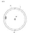
- FIG. 6 is a plan view of a protection net 30.
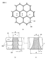
- A An enlarged view of the mesh 300, (b) a BB sectional view, and (c) a sectional view of a conventional protective net.
- FIG. 1 is a view showing an embodiment of a vacuum pump according to the present invention, and is a cross-sectional view of a magnetic bearing type turbo molecular pump 1.
- the turbo molecular pump shown in FIG. 1 has a high gas load including a turbo molecular pump unit including a plurality of stages of moving blades 19 and a plurality of stages of stator blades 21, and a screw groove pump unit including a screw rotor 20 and a screw stator 23. It is a corresponding turbo molecular pump.
- a plurality of stages of moving blades 19 and a screw rotor 20 are formed on a rotor 4, and the rotor 4 is fixed to a rotating shaft 8 rotatably provided in a spindle housing 24.
- an upper radial sensor 13 an upper radial electromagnet 9, a motor stator 12, a lower radial electromagnet 10, a lower radial sensor 14 and a thrust electromagnet 11 are provided in this order from the upper side in the figure.
- the rotating shaft 8 is supported in a noncontacting manner by the radial electromagnets 9 and 10 and the thrust electromagnet 11, and is rotationally driven by a DC motor constituted by the motor stator 12 and a motor rotor on the rotating shaft side.
- the floating position of the rotating shaft 8 is detected by radial sensors 13 and 14 provided corresponding to the radial electromagnets 9 and 10 and the thrust electromagnet 11 and a thrust sensor 15.
- Protective bearings 16 and 17 provided on the upper and lower sides of the rotating shaft 8 are mechanical bearings and support the rotating shaft 8 when the magnetic bearings are not operating, and limit the floating position of the rotating shaft 8 Function.
- a plurality of stationary blades 21 and a screw stator 23 are provided on the base 6 in the casing 7.
- the stationary vanes 21 are held on the base 6 so as to be sandwiched by ring-shaped spacers 22 at the top and bottom, and the casing 7 is bolted to the base 6 so that the vanes 21 and the spacer 22 are at the upper end of the casing 7 It is fixed between the and the base 6.
- each stationary blade 21 is positioned at a predetermined position between the moving blades 19.
- the screw stator 23 is bolted onto the base 6.
- the gas molecules flowing from the intake port 7a are knocked down by the turbo molecular pump unit 2 in the figure and compressed and exhausted toward the downstream side.
- the screw rotor 20 is provided in proximity to the inner circumferential surface of the screw stator 23, and a spiral groove is formed on the inner circumferential surface of the screw stator 23.
- exhaust by viscous flow is performed by the spiral groove of the screw stator 23 and the screw rotor 20 rotating at high speed.
- the gas molecules compressed by the turbo molecular pump unit 2 are further compressed by the thread groove pump unit 3 and discharged from the exhaust port 6a.
- the intake port 7a of the casing 7 is provided with a protective net 30 for preventing the entry of foreign matter from the apparatus side.
- the attachment of the protective net 30 to the casing 7 is performed by engaging the claw formed on the protective net 30 with the hole on the casing 7 side or pressing the periphery of the protective net 30 with a C-shaped ring.
- FIG. 2 is a plan view of the protective net 30, and a mesh 300 which is a hexagonal mesh is formed on the entire surface of a region A surrounded by a two-dot chain line.
- the protection net 30 is formed by, for example, stacking three net members 30a (see FIG. 3B).
- a pair of positioning holes 302 for forming the net members 30a is formed.
- the shape of the mesh 300 is not limited to a hexagon.
- FIG. 3 is a view for explaining the protection net 30, (a) is an enlarged view of a plurality of meshes 300 in the central part of FIG. 2, and (b) is a view showing a cross section of the beam 301 taken along BB. It is. Further, FIG. 3C shows a cross section of a beam portion of a conventional protective net.
- a metal plate of thickness t is etched to form a mesh 300.
- Materials such as stainless steel and aluminum are used for the metal plate.
- W is the width dimension (design value) of the beam 301.
- the diameter dimension of the mesh 300 is determined so that foreign matter can not pass through, and the width dimension W of the beam 301 is set so as to satisfy the required aperture ratio.
- the width dimension W is set to, for example, about 0.3 mm.
- the thickness t is determined in terms of strength.
- a leak operation may be performed in which a gas at atmospheric pressure is introduced to the pump inlet side or the pump outlet side.
- a pressure corresponding to the pressure difference between the front and back acts on the entire surface of the protective net 30, the thickness t is set so as to withstand such use.
- symbol C of FIG.3 (c) has shown the sag by etching.
- the width dimension increases toward the lower side of the cross section due to the occurrence of the sag C.
- the sag C at the corner of the beam 301 appears notably.
- the dimension L in the width direction of the sag C is about 25 to 40% of the plate thickness t. Therefore, assuming that the plate thickness t is 1 mm, the dimension L is approximately 0.25 to 0.4 mm, which is approximately the same as the width dimension W of the beam 301 (0.3 mm in the above example), and the aperture ratio decreases The decrease in exhaust speed due to
- a plurality of net members 30a on which the mesh 300 is formed by etching are stacked to form an integral protective net 30, thereby reducing the influence of sagging. I try to suppress. Since three net members 30a of the same thickness are used in the example of FIG. 3 (b), when the thickness of the protective net 30 is t, the thickness of each net member 30a can be held to t / 3. . Therefore, the dimension of the portion of the sag C in each net member 30a is 1/3, that is, L / 3 when using the plate material of thickness t.
- a method using an adhesive, a method of welding by spot welding or the like, a diffusion bonding method, or the like can be used as a method of overlapping and integrally forming the etched net members 30a.
- the bars are passed through the positioning holes 302 to overlap so that the positions of the upper and lower beams 301 coincide.
- the protection net 30 is integrated by suitable diffusion bonding.
- Diffusion bonding is a method in which a base material is brought into close contact and pressurized under temperature conditions lower than the melting point of the base material, and bonding is performed using diffusion of atoms generated between bonding surfaces.
- the bonding interface is recrystallized due to the diffusion of atoms between materials, and bonding is performed at the atomic level, so that the adhesion is good, and the same strength as in the case of forming a single plate material can be obtained.
- the net member 30a does not peel off.
- they may be integrated by adhesion, welding or the like. In the case of spot welding, there are disadvantages such as deformation caused by welding and differences in strength between the welded portion and the non-welded portion.
- bonding there is a concern about gas release from the adhesive.
- the protective net 30 used in the vacuum pump according to the present embodiment has a plurality of net members 30a on which a plurality of meshes 300 are formed by etching, which are integrally formed.
- the influence of C can be reduced.
- the decrease in the aperture ratio of the protective net 30 due to the occurrence of the dripping C can be suppressed to a low level.
- by bonding the laminated net members 30a by diffusion bonding to integrate them there is no influence on vacuum due to gas release and protection having the same strength as in the case of using a plate material of the same thickness.
- the net 30 can be obtained.
- the protection net used in the turbo molecular pump has been described as an example, but a vacuum pump including a protection net that rotates at high speed and has a protection net preventing foreign matter mixing, such as a drag pump Can also be applied. Further, the present invention is not limited to the above embodiment as long as the features of the present invention are not impaired.
Landscapes
- Engineering & Computer Science (AREA)
- Mechanical Engineering (AREA)
- General Engineering & Computer Science (AREA)
- Non-Positive Displacement Air Blowers (AREA)
- Structures Of Non-Positive Displacement Pumps (AREA)
Abstract
真空ポンプは、高速回転する回転体と、吸気口が形成され、回転体を収容するポンプケーシングと、吸気口に装着され、複数の開口がエッチング加工された板材を複数積層して一体とした保護ネット、とを備える。複数の板材を積層することにより板材1枚当たりの厚さが小さくなり、エッチング時のダレの影響も小さくなる。その結果、エッチングによる保護ネットの開口率低下を、低く抑えることができる。
Description
本発明は、エッチング加工による保護ネットを備えたターボ分子ポンプや真空ポンプに関する。
一般的に、ターボ分子ポンプのように高速回転する回転体を備える真空ポンプでは、異物(ウェハ破片やボルト等)がポンプ内に入らないように吸気口に保護ネットが設けられている(例えば、引用文献1参照)。保護ネットは薄板に六角形や正方形のメッシュを多数形成したものであり、異物の落下を防止するとともに排気速度の低下を招かないようにメッシュの大きさを設定するため、メッシュ間のネット(板部分)の線幅が非常に狭く設定されている。そのため、ネット部分を機械加工で形成するは難しく、通常はエッチング加工によりメッシュを形成している。
しかしながら、薄板を一方の面からエッチング加工した場合、いわゆるエッチングのダレによって他方の面側における線幅が設計よりも太くなってしまう。そのため、保護ネットの開口率が設計値よりも小さくなってしまい、排気速度が設計値よりも小さくなってしまうという問題があった。ダレは板厚が大きくなるほど著しくなるので、保護ネットの径が大きくなって板厚が厚くなるほど、排気速度の低下も著しくなる。
本発明による真空ポンプは、高速回転する回転体と、吸気口が形成され、回転体を収容するポンプケーシングと、吸気口に装着され、複数の開口がエッチング加工されたネット板材を複数積層して一体とした保護ネット、とを備える。
ネット板材は、アルミまたはステンレスなどの金属で構成される。また、エッチング加工されたネット板材の梁部は、厚さ方向で幅の異なる断面形状を有している。
保護ネットは、複数のネット板材を拡散接合により接合して一体としたものでも良い。
真空ポンプは、複数の回転翼が形成された回転体と、回転翼に対して回転軸方向に交互に配置された固定翼とを備えるターボ分子ポンプであっても良い。
ネット板材は、アルミまたはステンレスなどの金属で構成される。また、エッチング加工されたネット板材の梁部は、厚さ方向で幅の異なる断面形状を有している。
保護ネットは、複数のネット板材を拡散接合により接合して一体としたものでも良い。
真空ポンプは、複数の回転翼が形成された回転体と、回転翼に対して回転軸方向に交互に配置された固定翼とを備えるターボ分子ポンプであっても良い。
本発明によれば、保護ネットの強度を維持しつつ、エッチング加工の影響による排気性能低下を抑えることができる。
以下、図を参照して本発明を実施するための最良の形態について説明する。図1は、本発明による真空ポンプの一実施の形態を示す図であり、磁気軸受式ターボ分子ポンプ1の断面図である。図1に示すターボ分子ポンプは、複数段の動翼19および複数段の静翼21で構成されるターボ分子ポンプ部と、ネジロータ20およびネジステータ23で構成されネジ溝ポンプ部とを備える高ガス負荷対応型のターボ分子ポンプである。
複数段の動翼19およびネジロータ20はロータ4に形成されており、そのロータ4はスピンドルハウジング24内に回転自在に設けられた回転軸8に固定されている。スピンドルハウジング24内には、図示上側から順に、上部ラジアルセンサ13,上部ラジアル電磁石9,モータステータ12,下部ラジアル電磁石10,下部ラジアルセンサ14およびスラスト電磁石11が設けられている。
回転軸8はラジアル電磁石9,10およびスラスト電磁石11によって非接触支持され、モータステータ12と回転軸側のモータロータとで構成されるDCモータにより回転駆動される。回転軸8の浮上位置は、各ラジアル電磁石9,10およびスラスト電磁石11に対応して設けられたラジアルセンサ13,14およびスラストセンサ15によって検出される。回転軸8の上下に設けられた保護ベアリング16,17は機械式のベアリングであり、磁気軸受が作動していない場合に回転軸8を支持するとともに、回転軸8の浮上位置を制限するものとして機能する。
一方、ケーシング7内のベース6上には、複数の静翼21およびネジステータ23が設けられている。各静翼21は上下をリング状のスペーサ22によって挟持されるようにベース6上に保持されており、ケーシング7をベース6にボルト締結することにより、静翼21およびスペーサ22がケーシング7の上端とベース6との間に固定される。その結果、各静翼21は動翼19間の所定位置に位置決めされる。ネジステータ23は、ベース6上にボルト締結されている。
吸気口7aから流入したガス分子はターボ分子ポンプ部2によって図示下方へと叩き飛ばされ、下流側に向かって圧縮排気される。ネジロータ20はネジステータ23の内周面に近接して設けられており、ネジステータ23内周面には螺旋溝が形成されている。ネジ溝ポンプ部3では、ネジステータ23の螺旋溝と高速回転するネジロータ20とにより、粘性流による排気が行われる。ターボ分子ポンプ部2で圧縮されたガス分子は、さらにネジ溝ポンプ部3によって圧縮され、排気口6aから排出される。
ケーシング7の吸気口7aには、装置側からの異物の混入を防止するための保護ネット30が設けられている。保護ネット30のケーシング7への取付は、保護ネット30に形成された爪をケーシング7側の穴に係合させたり、C型リングで保護ネット30の周囲を押さえるようにしたりして行われる。
図2は保護ネット30の平面図であり、二点差線で囲まれた領域Aの全面に六角形の網目であるメッシュ300が形成されている。後述するように、保護ネット30は、例えば3枚のネット部材30a(図3(b)参照)を積層して構成されている。保護ネット30の縁部には、ネット部材30aを積層する際の位置決め用の孔302が一対形成されている。なお、メッシュ300の形状は六角形に限らない。
図3は保護ネット30を説明する図であり、(a)は図2の中央部分の複数のメッシュ300を拡大して示したもので、(b)は梁301のB-B断面を示す図である。また、図3(c)は、従来の保護ネットの梁部分の断面を示したものである。
従来の保護ネットは、図3(c)に示すように、厚さtの金属板をエッチング加工してメッシュ300を形成している。金属板にはステンレスやアルミなどの材料が用いられる。Wは梁301の幅寸法(設計値)である。保護ネット30を設計する場合には、異物が通過できないようにメッシュ300の径寸法を決定するとともに、要求開口率を満足するように梁301の幅寸法Wを設定する。幅寸法Wは、例えば、0.3mm程度に設定される。さらに、強度上の観点から厚さtが決定される。
例えば、ターボ分子ポンプを半導体装置等で使用する場合、ポンプ吸気口側またはポンプ排気口側に大気圧のガスを導入するリーク動作を行う場合がある。その場合には、保護ネット30の全面に、表裏の差圧に相当する圧力が作用するため、そのような使用にも耐えられるように、厚さtが設定される。
図3(c)の符号Cで示す部分はエッチングによるダレを示している。図3(c)に示す例では上面側からエッチングを行っているため、ダレCの発生により、断面の下側ほど幅寸法が大きくなっている。特に、図3(a)に示すように、梁301の角部におけるダレCが顕著に現れる。
一般的に、ダレCの幅方向の寸法Lは、板厚tの25~40%程度となる。そのため、板厚tを1mmと仮定すると、寸法Lは0.25~0.4mm程度となり、梁301の幅寸法W(上述した例では0.3mm)と同程度となってしまい、開口率低下による排気速度の低下が無視できないくらい大きくなってしまう。
そこで、本実施の形態では、図3(b)に示すように、エッチング加工してメッシュ300を形成したネット部材30aを複数枚重ねて一体の保護ネット30とすることにより、ダレの影響を小さく抑えるようにしている。図3(b)の例では同一厚さのネット部材30aを3枚用いているので、保護ネット30の厚さをtとすると、各ネット部材30aの厚さをt/3に押さえることができる。そのため、各ネット部材30aにおけるダレCの部分の寸法は、厚さtの板材を用いた場合の1/3,すなわちL/3となる。
上述したように、ダレCの幅方向の寸法Lが板厚tの25~40%であると仮定すると、従来のように、厚さtの板材を1枚用いて形成した場合には、梁301の最大幅寸法W’は、「W+0.5t<W’<W+0.8t」となる。例えば、t=0.9mm、W=0.3mmとした場合、0.75mm<W’<1.02mmとなり、設計値W=0.3mmの2.5~3.4倍とかなり大きくなってしまう。一方、図3(b)のように厚さt/3のネット部材30aを3枚用いた場合には、0.45mm<W’<0.54mmとなり、設計値の1.5~1.8倍に抑えることができる。
エッチング加工したネット部材30aを重ねて一体とする方法としては、接着剤を用いる方法や、スポット溶接等で溶接する方法や、拡散接合法などを用いることができる。積層の際には、位置決め用孔302に棒材を通すなどして、上下の梁301の位置が一致するように重ねる。
本実施形態では、保護ネット30に好適な拡散接合により一体としている。拡散接合とは、母材を密着させて母材の融点以下の温度条件で加圧し、接合面間に生じる原子の拡散を利用して接合する方法である。拡散接合では、材料間の原子の拡散により接合界面が再結晶化され、原子レベルで接合するため密着力が良く、1枚の板材で形成した場合と同等の強度を得ることができる。また、ネット部材30aが剥がれることもない。もちろん、接着や溶接等により一体化しても良い。スポット溶接の場合、溶接により変形が生じたり、溶接されている部分と溶接されていない部分とで強度が異なるという欠点がある。また、接着の場合には、接着剤からのガス放出が懸念される。
上述したように、本実施の形態の真空ポンプに用いられている保護ネット30は、エッチング加工により複数のメッシュ300を形成したネット部材30aを複数積層して一体としているので、エッチング加工時のダレCの影響を低減することができる。その結果、ダレCの発生による保護ネット30の開口率の低下を、低く押さえることができる。また、積層されたネット部材30aを拡散接合により接合して一体とすることにより、ガス放出等による真空への影響が無く、また、同じ厚さの板材を用いた場合と同等の強度を有する保護ネット30を得ることができる。
なお、上述した実施の形態では、ターボ分子ポンプに用いられる保護ネットを例に説明したが、高速回転する回転体を備え、異物の混入を防止する保護ネットを備える真空ポンプ、例えばドラッグポンプなどにも適用することができる。また、本発明の特徴を損なわない限り、本発明は上記実施の形態に何ら限定されるものではない。
Claims (7)
- 高速回転する回転体と、
吸気口が形成され、前記回転体を収容するポンプケーシングと、
前記吸気口に装着され、複数の開口がエッチング加工されたネット板材を複数積層して一体とした保護ネット、とを備えることを特徴とする真空ポンプ。 - 請求項1に記載の真空ポンプにおいて、
前記ネット板材を金属で構成したことを特徴とする真空ポンプ。 - 請求項2に記載の真空ポンプにおいて、
前記ネット板材をアルミまたはステンレスで構成したことを特徴とする真空ポンプ。 - 請求項1~3のいずれか一項に記載の真空ポンプにおいて、
前記エッチング加工されたネット板材の梁部は、厚さ方向で幅の異なる断面形状を有していることを特徴とする真空ポンプ。 - 請求項1に記載の真空ポンプにおいて、
前記複数のネット板材を拡散接合により接合して一体としたことを特徴とする真空ポンプ。 - 請求項1~5のいずれか一項に記載の真空ポンプにおいて、
前記真空ポンプは、複数の回転翼が形成された回転体と、前記回転翼に対して回転軸方向に交互に配置された固定翼とを備えるターボ分子ポンプであることを特徴とする真空ポンプ。 - 請求項1~8のいずれかに記載の真空ポンプに用いることを特徴とする保護ネット。
Priority Applications (2)
| Application Number | Priority Date | Filing Date | Title |
|---|---|---|---|
| JP2010541180A JP5397385B2 (ja) | 2008-12-05 | 2008-12-05 | 真空ポンプ、ターボ分子ポンプおよび保護ネット |
| PCT/JP2008/072171 WO2010064321A1 (ja) | 2008-12-05 | 2008-12-05 | 真空ポンプ、ターボ分子ポンプおよび保護ネット |
Applications Claiming Priority (1)
| Application Number | Priority Date | Filing Date | Title |
|---|---|---|---|
| PCT/JP2008/072171 WO2010064321A1 (ja) | 2008-12-05 | 2008-12-05 | 真空ポンプ、ターボ分子ポンプおよび保護ネット |
Publications (1)
| Publication Number | Publication Date |
|---|---|
| WO2010064321A1 true WO2010064321A1 (ja) | 2010-06-10 |
Family
ID=42232985
Family Applications (1)
| Application Number | Title | Priority Date | Filing Date |
|---|---|---|---|
| PCT/JP2008/072171 Ceased WO2010064321A1 (ja) | 2008-12-05 | 2008-12-05 | 真空ポンプ、ターボ分子ポンプおよび保護ネット |
Country Status (2)
| Country | Link |
|---|---|
| JP (1) | JP5397385B2 (ja) |
| WO (1) | WO2010064321A1 (ja) |
Cited By (12)
| Publication number | Priority date | Publication date | Assignee | Title |
|---|---|---|---|---|
| WO2014049728A1 (ja) * | 2012-09-26 | 2014-04-03 | 株式会社島津製作所 | 真空ポンプ用保護ネット、その製造方法および真空ポンプ |
| JP2021526297A (ja) * | 2018-05-31 | 2021-09-30 | マイクロマス ユーケー リミテッド | ベンチトップ飛行時間型質量分析計 |
| US20210355966A1 (en) * | 2018-10-31 | 2021-11-18 | Edwards Japan Limited | Vacuum pump, protective net, and contact part |
| US11355331B2 (en) | 2018-05-31 | 2022-06-07 | Micromass Uk Limited | Mass spectrometer |
| US11367607B2 (en) | 2018-05-31 | 2022-06-21 | Micromass Uk Limited | Mass spectrometer |
| US11373849B2 (en) | 2018-05-31 | 2022-06-28 | Micromass Uk Limited | Mass spectrometer having fragmentation region |
| US11437226B2 (en) | 2018-05-31 | 2022-09-06 | Micromass Uk Limited | Bench-top time of flight mass spectrometer |
| US11476103B2 (en) | 2018-05-31 | 2022-10-18 | Micromass Uk Limited | Bench-top time of flight mass spectrometer |
| US11538676B2 (en) | 2018-05-31 | 2022-12-27 | Micromass Uk Limited | Mass spectrometer |
| US11621154B2 (en) | 2018-05-31 | 2023-04-04 | Micromass Uk Limited | Bench-top time of flight mass spectrometer |
| US12009193B2 (en) | 2018-05-31 | 2024-06-11 | Micromass Uk Limited | Bench-top Time of Flight mass spectrometer |
| US12027359B2 (en) | 2018-05-31 | 2024-07-02 | Micromass Uk Limited | Bench-top Time of Flight mass spectrometer |
Citations (3)
| Publication number | Priority date | Publication date | Assignee | Title |
|---|---|---|---|---|
| JPH02229512A (ja) * | 1989-12-08 | 1990-09-12 | Wada Shoichi | 濾材用多孔板の鍍金処理製造方法 |
| JP2002316013A (ja) * | 2001-04-18 | 2002-10-29 | Minoru Kitano | 濾過フィルター |
| JP2006299968A (ja) * | 2005-04-21 | 2006-11-02 | Shimadzu Corp | 異物侵入防止板、回転真空ポンプおよび真空システム |
Family Cites Families (5)
| Publication number | Priority date | Publication date | Assignee | Title |
|---|---|---|---|---|
| JP2963733B2 (ja) * | 1990-06-29 | 1999-10-18 | 株式会社東芝 | 井形格子の製造方法 |
| JPH04300308A (ja) * | 1991-03-22 | 1992-10-23 | Nhk Spring Co Ltd | 樹脂供給装置のブレーカプレート |
| JPH10118569A (ja) * | 1996-10-19 | 1998-05-12 | Ricoh Co Ltd | 微細粒子分級用フィルター及びその製造方法 |
| JP2006017421A (ja) * | 2004-07-05 | 2006-01-19 | Fuji Electric Holdings Co Ltd | 冷凍機の熱交換器 |
| TWI292473B (en) * | 2005-08-26 | 2008-01-11 | Smc Kk | Flow meter |
-
2008
- 2008-12-05 JP JP2010541180A patent/JP5397385B2/ja not_active Expired - Fee Related
- 2008-12-05 WO PCT/JP2008/072171 patent/WO2010064321A1/ja not_active Ceased
Patent Citations (3)
| Publication number | Priority date | Publication date | Assignee | Title |
|---|---|---|---|---|
| JPH02229512A (ja) * | 1989-12-08 | 1990-09-12 | Wada Shoichi | 濾材用多孔板の鍍金処理製造方法 |
| JP2002316013A (ja) * | 2001-04-18 | 2002-10-29 | Minoru Kitano | 濾過フィルター |
| JP2006299968A (ja) * | 2005-04-21 | 2006-11-02 | Shimadzu Corp | 異物侵入防止板、回転真空ポンプおよび真空システム |
Cited By (15)
| Publication number | Priority date | Publication date | Assignee | Title |
|---|---|---|---|---|
| WO2014049728A1 (ja) * | 2012-09-26 | 2014-04-03 | 株式会社島津製作所 | 真空ポンプ用保護ネット、その製造方法および真空ポンプ |
| US9976572B2 (en) | 2012-09-26 | 2018-05-22 | Shimadzu Corporation | Vacuum pump protection net, method for manufacturing the same, and vacuum pump |
| US11476103B2 (en) | 2018-05-31 | 2022-10-18 | Micromass Uk Limited | Bench-top time of flight mass spectrometer |
| JP7039736B2 (ja) | 2018-05-31 | 2022-03-22 | マイクロマス ユーケー リミテッド | ベンチトップ飛行時間型質量分析計 |
| US11355331B2 (en) | 2018-05-31 | 2022-06-07 | Micromass Uk Limited | Mass spectrometer |
| US11367607B2 (en) | 2018-05-31 | 2022-06-21 | Micromass Uk Limited | Mass spectrometer |
| US11373849B2 (en) | 2018-05-31 | 2022-06-28 | Micromass Uk Limited | Mass spectrometer having fragmentation region |
| US11437226B2 (en) | 2018-05-31 | 2022-09-06 | Micromass Uk Limited | Bench-top time of flight mass spectrometer |
| JP2021526297A (ja) * | 2018-05-31 | 2021-09-30 | マイクロマス ユーケー リミテッド | ベンチトップ飛行時間型質量分析計 |
| US11538676B2 (en) | 2018-05-31 | 2022-12-27 | Micromass Uk Limited | Mass spectrometer |
| US11621154B2 (en) | 2018-05-31 | 2023-04-04 | Micromass Uk Limited | Bench-top time of flight mass spectrometer |
| US11879470B2 (en) | 2018-05-31 | 2024-01-23 | Micromass Uk Limited | Bench-top time of flight mass spectrometer |
| US12009193B2 (en) | 2018-05-31 | 2024-06-11 | Micromass Uk Limited | Bench-top Time of Flight mass spectrometer |
| US12027359B2 (en) | 2018-05-31 | 2024-07-02 | Micromass Uk Limited | Bench-top Time of Flight mass spectrometer |
| US20210355966A1 (en) * | 2018-10-31 | 2021-11-18 | Edwards Japan Limited | Vacuum pump, protective net, and contact part |
Also Published As
| Publication number | Publication date |
|---|---|
| JP5397385B2 (ja) | 2014-01-22 |
| JPWO2010064321A1 (ja) | 2012-05-10 |
Similar Documents
| Publication | Publication Date | Title |
|---|---|---|
| JP5397385B2 (ja) | 真空ポンプ、ターボ分子ポンプおよび保護ネット | |
| JP6644813B2 (ja) | 真空ポンプ及び該真空ポンプに用いられる可撓性カバー及びロータ | |
| JP5676453B2 (ja) | ターボ分子ポンプおよびロータの製造方法 | |
| US9976572B2 (en) | Vacuum pump protection net, method for manufacturing the same, and vacuum pump | |
| JP6331491B2 (ja) | 真空ポンプ | |
| TW201807317A (zh) | 真空泵 | |
| KR101883026B1 (ko) | 진공 펌프와 그 로터 | |
| US8403652B2 (en) | Molecular pump and flange having shock absorbing member | |
| JP2017110627A (ja) | 真空ポンプ及び該真空ポンプに搭載される回転翼、反射機構 | |
| JP5532051B2 (ja) | 真空ポンプ | |
| US20080304985A1 (en) | Turbo-molecular pump | |
| JP6390098B2 (ja) | 真空ポンプ | |
| JP5577798B2 (ja) | ターボ分子ポンプ | |
| US9879553B2 (en) | Fixed blade assembly usable in exhaust pump, and exhaust pump provided with same | |
| JP2020122487A (ja) | 真空ポンプ | |
| JP5250201B2 (ja) | 真空ポンプ | |
| JP2004278500A (ja) | 分子ポンプ | |
| WO2007004542A1 (ja) | ターボ分子ポンプ | |
| JP2006291794A (ja) | 真空ポンプのロータ | |
| JP6079041B2 (ja) | ターボ分子ポンプ、及び、ターボ分子ポンプ用の補強部材 | |
| JP7424007B2 (ja) | 真空ポンプ | |
| JP4853266B2 (ja) | ターボ分子ポンプ | |
| JP2008280977A (ja) | ターボ分子ポンプ | |
| WO2017159730A1 (ja) | インペラ、回転機械、およびインペラの製造方法 | |
| JP2001173588A (ja) | 真空ポンプ |
Legal Events
| Date | Code | Title | Description |
|---|---|---|---|
| 121 | Ep: the epo has been informed by wipo that ep was designated in this application |
Ref document number: 08878581 Country of ref document: EP Kind code of ref document: A1 |
|
| WWE | Wipo information: entry into national phase |
Ref document number: 2010541180 Country of ref document: JP |
|
| NENP | Non-entry into the national phase |
Ref country code: DE |
|
| 122 | Ep: pct application non-entry in european phase |
Ref document number: 08878581 Country of ref document: EP Kind code of ref document: A1 |