WO2010061707A1 - 等速自在継手用外側継手部材 - Google Patents
等速自在継手用外側継手部材 Download PDFInfo
- Publication number
- WO2010061707A1 WO2010061707A1 PCT/JP2009/068448 JP2009068448W WO2010061707A1 WO 2010061707 A1 WO2010061707 A1 WO 2010061707A1 JP 2009068448 W JP2009068448 W JP 2009068448W WO 2010061707 A1 WO2010061707 A1 WO 2010061707A1
- Authority
- WO
- WIPO (PCT)
- Prior art keywords
- frp layer
- constant velocity
- velocity universal
- diameter surface
- joint member
- Prior art date
- Legal status (The legal status is an assumption and is not a legal conclusion. Google has not performed a legal analysis and makes no representation as to the accuracy of the status listed.)
- Ceased
Links
Images





Classifications
-
- F—MECHANICAL ENGINEERING; LIGHTING; HEATING; WEAPONS; BLASTING
- F16—ENGINEERING ELEMENTS AND UNITS; GENERAL MEASURES FOR PRODUCING AND MAINTAINING EFFECTIVE FUNCTIONING OF MACHINES OR INSTALLATIONS; THERMAL INSULATION IN GENERAL
- F16D—COUPLINGS FOR TRANSMITTING ROTATION; CLUTCHES; BRAKES
- F16D3/00—Yielding couplings, i.e. with means permitting movement between the connected parts during the drive
- F16D3/16—Universal joints in which flexibility is produced by means of pivots or sliding or rolling connecting parts
- F16D3/20—Universal joints in which flexibility is produced by means of pivots or sliding or rolling connecting parts one coupling part entering a sleeve of the other coupling part and connected thereto by sliding or rolling members
- F16D3/22—Universal joints in which flexibility is produced by means of pivots or sliding or rolling connecting parts one coupling part entering a sleeve of the other coupling part and connected thereto by sliding or rolling members the rolling members being balls, rollers, or the like, guided in grooves or sockets in both coupling parts
- F16D3/223—Universal joints in which flexibility is produced by means of pivots or sliding or rolling connecting parts one coupling part entering a sleeve of the other coupling part and connected thereto by sliding or rolling members the rolling members being balls, rollers, or the like, guided in grooves or sockets in both coupling parts the rolling members being guided in grooves in both coupling parts
- F16D3/224—Universal joints in which flexibility is produced by means of pivots or sliding or rolling connecting parts one coupling part entering a sleeve of the other coupling part and connected thereto by sliding or rolling members the rolling members being balls, rollers, or the like, guided in grooves or sockets in both coupling parts the rolling members being guided in grooves in both coupling parts the groove centre-lines in each coupling part lying on a sphere
-
- F—MECHANICAL ENGINEERING; LIGHTING; HEATING; WEAPONS; BLASTING
- F16—ENGINEERING ELEMENTS AND UNITS; GENERAL MEASURES FOR PRODUCING AND MAINTAINING EFFECTIVE FUNCTIONING OF MACHINES OR INSTALLATIONS; THERMAL INSULATION IN GENERAL
- F16D—COUPLINGS FOR TRANSMITTING ROTATION; CLUTCHES; BRAKES
- F16D3/00—Yielding couplings, i.e. with means permitting movement between the connected parts during the drive
- F16D3/16—Universal joints in which flexibility is produced by means of pivots or sliding or rolling connecting parts
- F16D3/20—Universal joints in which flexibility is produced by means of pivots or sliding or rolling connecting parts one coupling part entering a sleeve of the other coupling part and connected thereto by sliding or rolling members
- F16D3/22—Universal joints in which flexibility is produced by means of pivots or sliding or rolling connecting parts one coupling part entering a sleeve of the other coupling part and connected thereto by sliding or rolling members the rolling members being balls, rollers, or the like, guided in grooves or sockets in both coupling parts
- F16D3/223—Universal joints in which flexibility is produced by means of pivots or sliding or rolling connecting parts one coupling part entering a sleeve of the other coupling part and connected thereto by sliding or rolling members the rolling members being balls, rollers, or the like, guided in grooves or sockets in both coupling parts the rolling members being guided in grooves in both coupling parts
- F16D3/2237—Universal joints in which flexibility is produced by means of pivots or sliding or rolling connecting parts one coupling part entering a sleeve of the other coupling part and connected thereto by sliding or rolling members the rolling members being balls, rollers, or the like, guided in grooves or sockets in both coupling parts the rolling members being guided in grooves in both coupling parts where the grooves are composed of radii and adjoining straight lines, i.e. undercut free [UF] type joints
-
- F—MECHANICAL ENGINEERING; LIGHTING; HEATING; WEAPONS; BLASTING
- F16—ENGINEERING ELEMENTS AND UNITS; GENERAL MEASURES FOR PRODUCING AND MAINTAINING EFFECTIVE FUNCTIONING OF MACHINES OR INSTALLATIONS; THERMAL INSULATION IN GENERAL
- F16D—COUPLINGS FOR TRANSMITTING ROTATION; CLUTCHES; BRAKES
- F16D2250/00—Manufacturing; Assembly
-
- F—MECHANICAL ENGINEERING; LIGHTING; HEATING; WEAPONS; BLASTING
- F16—ENGINEERING ELEMENTS AND UNITS; GENERAL MEASURES FOR PRODUCING AND MAINTAINING EFFECTIVE FUNCTIONING OF MACHINES OR INSTALLATIONS; THERMAL INSULATION IN GENERAL
- F16D—COUPLINGS FOR TRANSMITTING ROTATION; CLUTCHES; BRAKES
- F16D2300/00—Special features for couplings or clutches
- F16D2300/10—Surface characteristics; Details related to material surfaces
Definitions
- the present invention relates to an outer joint member of a constant velocity universal joint used in power transmission systems of automobiles and various industrial machines.
- Constant velocity universal joints generally include an outer ring as an outer joint member having a track groove formed on the inner diameter surface and an inner ring as an inner joint member having a track groove formed on the outer diameter surface.
- a plurality of balls interposed between the outer ring track groove and the inner ring track groove for transmitting torque; and a cage holding the ball interposed between the inner ring surface of the outer ring and the outer ring surface of the inner ring. It has.
- the present invention intends to provide an outer joint member for a constant velocity universal joint that can be significantly reduced in weight without a decrease in strength.
- the outer joint member for a constant velocity universal joint is a metal having a cup portion in which a plurality of track grooves are formed on the inner diameter surface in the outer joint member for constant velocity universal joints formed with a plurality of track grooves on the inner diameter surface.
- a main body and an FRP layer covering the outer diameter surface of the cup portion of the metal main body are provided.
- the outer joint member for a constant velocity universal joint of the present invention it is possible to reduce the weight by covering the outer diameter surface of the cup portion of the metal main body with the FRP layer.
- the strength of the outer joint member of the constant velocity universal joint is mainly a tensile force acting in the circumferential direction on the outer diameter surface of the cup portion in which a plurality of track grooves are formed on the inner diameter surface.
- the FRP layer receives the load added to an outer joint member.
- FRP Fiber Reinforced Plastics
- FRP is a fiber reinforced plastic.
- FRP is called GFRP (glass fiber reinforced plastic), CFRP (carbon fiber reinforced plastic), AFRP, or KFRP (aramid fiber reinforced plastic) depending on the fiber used.
- the resin to be used is typically a thermosetting resin such as an unsaturated polyester resin, an epoxy resin, or a phenol resin, but a thermoplastic resin such as polypropylene, nylon, or polycarbonate can also be used.
- the FRP cylinder is formed by winding FRP infiltrated into a synthetic resin agent around a mandrel by the filament winding method, and the FRP layer is formed, or the FRP infiltrated with the synthetic resin agent is in the filament winding method Alternatively, the FRP layer can be formed by winding the outer periphery of the metal main body by a sheet winding method.
- the filament winding method is a method in which a carbon fiber (fiber bundle) impregnated with resin is wound around a mandrel, molded, heated and cured, and then the mandrel is removed. “Sheet winding” is to wind a sheet instead of a bundle of fibers.
- the FRP layer is spirally wound until it reaches a predetermined thickness so that the orientation angles are alternately arranged at angles of + 5 ° to + 90 ° and ⁇ 5 ° to ⁇ 90 ° with respect to the axial direction. It may be provided.
- the FRP layer may protrude outward from the opening end of the cup portion of the metal main body. As a result, the FRP layer covers the opening end of the cup portion from the outer diameter side, and the diameter of the opening portion of the cup portion can be prevented from expanding.
- the FRP layer can be composed of a plurality of types of short FRP layer portions. As described above, if a plurality of types of short FRP layer portions are provided, the strength of the FRP layer can be changed in the axial direction and can be tuned according to the use situation.
- Concave and convex fitting having a convex portion extending in the axial direction and a concave portion extending in the axial direction and fitting into the convex portion between the inner diameter surface of the FRP layer and the outer diameter surface of the cup portion of the metal body. It is preferable to provide a structural part. By providing the concave-convex fitting structure portion, it is possible to suppress a circumferential shift between the metal main body and the FRP layer.
- a convex portion extending in the axial direction is formed on the outer diameter surface of the metal main body, and the convex portion is press-fitted into the inner diameter portion of the FRP layer, and by this press fitting, the convex portion is fitted to the inner diameter surface of the FRP layer.
- a concave portion can be formed to constitute the concave-convex fitting structure portion. In such a concave-convex fitting structure portion, the bonding property between the convex portion and the concave portion is excellent.
- a boot mounting groove is formed in the outer diameter surface on the opening side of the cup portion of the metal main body, and a notch for fitting the FRP layer is provided on the outer diameter surface on the opposite side of the boot mounting groove. It may be.
- the boot mounting groove can be formed into a metal with excellent workability (for example, steel), and the amount of FRP used can be suppressed.
- the boot mounting groove may be provided on the outer diameter surface of the FRP layer. In this case, the range of the FRP layer is increased, and further weight reduction can be achieved.
- a crimping portion that is crimped to the outer diameter side and engages with the FRP layer may be provided at the opening end of the cup portion of the metal main body.
- the caulking portion can prevent the FRP layer from coming off from the cup portion of the metal main body in the axial direction.
- the metal body and the FRP layer are made of different materials, the expansion coefficient is different, and the FRP layer may be loosely fitted to the metal body. Even in such a case, The caulking portion can prevent the FRP layer from coming off.
- the metal main body and the FRP layer may be bonded via an adhesive.
- the adhesive By using the adhesive in this manner, the fitting relationship of the FRP layer to the cup portion of the metal main body can be used as a gap, and the adhesive can be interposed in the gap.
- a protective film may be formed on the outer diameter surface of the FRP layer.
- the FRP layer can be protected, and damage to the FRP layer due to stepping stones from the outside can be prevented. If the FRP layer is made of CFRP, the strength is particularly excellent.
- the FRP layer can be formed by injection molding.
- the heat-melted material is injected into a mold closed by a cylinder or the like through a nozzle and cooled and solidified in the mold to obtain a desired molded product.
- the lightweight and high-strength FRP can handle the load, and the thin cup portion of the metal main body portion Can be achieved. That is, weight reduction can be realized without causing a decrease in strength.
- the FRP layer can be stably formed by the filament winding method or the sheet winding method, etc., and the productivity is excellent. Further, by winding in a spiral shape until a predetermined thickness is obtained so that the orientation angles are alternately arranged at an angle of 5 ° to + 90 ° and ⁇ 5 ° to ⁇ 90 °, the strength is increased. It is possible to constitute an excellent FRP layer.
- the FRP layer protrudes from the opening end of the cup part of the metal main body, the diameter of the opening part of the cup part can be prevented, and a strong and stable cup part can be configured.
- the FRP layer is provided with a plurality of types of short FRP layer parts, it can be tuned according to the use situation. For example, in the vicinity of the cup inlet end surface of the outer ring that tends to spread in the circumferential direction when torque is applied, the fiber winding angle is FRP with 80 to 90 deg to suppress deformation in the diameter expansion direction.
- the vicinity of the center of the cup is an FRP having a fiber winding angle of 45 deg and is a portion that increases torsional strength.
- a thin FRP can be fitted in the vicinity of the cup bottom having a relatively large wall thickness. In this way, by combining a plurality of ready-made FRPs (short FRP layer parts), it is not necessary to change the winding angle and thickness when manufacturing the FRP, making it easier to manufacture the FRP. It can be tuned to the optimum specification more easily.
- the concave-convex fitting structure portion By providing the concave-convex fitting structure portion, it is possible to suppress the circumferential shift between the metal main body and the FRP layer, and it is possible to maintain a stable state (fixed state between the metal main body and the FRP layer) over a long period of time. .
- the convex part on the metal main body side is press-fitted into the inner diameter part of the FRP layer, the joint between the convex part and the concave part is excellent, and a high-quality outer joint member can be provided.
- the boot mounting groove can be formed into a metal (for example, steel) having excellent workability, excellent productivity, and the amount of FRP used. Can be suppressed and contribute to cost reduction.
- the weight can be further reduced.
- the FRP layer can be prevented from coming off and the function as a constant velocity universal joint can be effectively exhibited over a long period of time.
- the fitting relation of the FRP layer to the cup portion of the metal main body may be a gap, and an adhesive may be interposed in the gap. it can.
- FRP is not directly wound around the cup portion of the metal main body, and the inner diameter surface of the FRP layer is the outer diameter surface of the cup portion of the metal main body even when the FRP layer is separately formed. There is no need to press it. That is, it is not necessary to finish the inner surface dimension of the FRP layer with high accuracy, and the productivity is excellent.
- the outer diameter surface of the FRP layer can be protected, and the FRP layer can be prevented from being deteriorated or damaged by a stepping stone or the like.
- the FRP layer is made of CFRP, it is particularly excellent in strength and can be reduced in weight effectively.
- the FRP layer can be formed by injection molding. That is, if injection molding is used when forming the FRP layer, it is possible to perform molding that takes advantage of injection molding such as molding of a complicated shape, molding in a short cycle, and material loss.
- FIG. 2 shows a constant velocity universal joint using the outer joint member according to the present invention.
- the constant velocity universal joint includes an outer ring 3 as an outer joint member in which a plurality of (for example, six) track grooves 2 are formed on the inner diameter surface 1 along the axial direction, and the track groove 2 of the outer ring 3 on the outer diameter surface 4.
- a plurality of (for example, six) track grooves 5 that are paired with the inner ring 6 as an inner joint member formed along the axial direction, and are interposed between the track grooves 2 of the outer ring 3 and the track grooves 5 of the inner ring 6.
- a female serration female spline (not shown), which is a torque transmission part, is formed on the inner diameter surface of the hole 10 of the inner ring 6. That is, the shaft 11 is fitted into the hole 10 of the inner ring 6, and the male serration (not shown) provided on the shaft 11 is fitted to the female serration of the inner ring 6. Thereby, torque between the shaft 11 and the inner ring 6 is transmitted.
- the outer ring 3 as an outer joint member includes a metal main body 15 having a cup portion 12 having a plurality of track grooves 2 formed on the inner diameter surface 1, and a cup of the metal main body 15. And an FRP layer 14 covering the outer diameter surface of the portion 12. That is, the metal main body 15 is made of medium carbon steel or the like, and includes the cup portion 12 and a shaft portion 13 protruding from the bottom wall 12a of the cup portion 12.
- the outer diameter surface 16 of the cup portion 12 of the metal main body 15 is a cylindrical surface, and the outer diameter surface 16 is covered with the cylindrical FRP layer 14.
- the FRP layer 14 is composed of an FRP cylinder 17 in which FRP infiltrated with a synthetic resin agent is wound around a mandrel by a filament winding method and baked.
- FRP Fiber Reinforced Plastics
- FRP is a fiber reinforced plastic.
- FRP is called GFRP (glass fiber reinforced plastic), CFRP (carbon fiber reinforced plastic), AFRP, or KFRP (aramid fiber reinforced plastic) depending on the fiber used.
- the resin to be used is typically a thermosetting resin such as an unsaturated polyester resin, an epoxy resin, or a phenol resin, but a thermoplastic resin such as polypropylene, nylon, or polycarbonate can also be used.
- FRP has the following characteristics. Excellent weather resistance, heat resistance, and chemical resistance. It has electrical insulation and excellent radio wave transmission. Excellent heat insulation. It can handle various shapes and can be colored freely. Lightweight and strong.
- the FRP cylinder 17 (see FIG. 3) constituting the FRP layer 14 is formed, and the FRP cylinder 17 is press-fitted into the outer diameter surface of the cup portion 12 of the metal main body 15.
- the FRP cylinder 17 is spiral until a predetermined thickness is obtained so that the orientation angles are alternately arranged at angles of + 5 ° to + 90 ° and ⁇ 5 ° to ⁇ 90 ° with respect to the axial direction. Is wound around.
- the weight can be reduced.
- the strength of the outer joint member of the constant velocity universal joint is mainly a tensile force acting in the circumferential direction on the outer diameter surface 16 of the cup portion 12 in which the plurality of track grooves 2 are formed on the inner diameter surface 1.
- the FRP layer 14 covers the outer diameter surface 16 of the cup portion 12 of the metal main body 15 so as to receive a load applied to the outer joint member.
- the open end portion 14 a of the FRP layer 14 protrudes outward from the open end 18 of the cup portion 12 of the metal main body 15.
- the FRP layer 14 of the cup part 12 covers the opening end 18 of the cup part 12 from the outer diameter side as described above.
- the diameter of the opening can be prevented from expanding. For this reason, the cup part 12 stable in strength can be configured.
- the protrusion amount A of the opening end portion 14a of the FRP layer 14 (the size of the opening end 18 of the cup portion 12 and the opening end 34 of the FRP layer 14) is too large, the entire outer ring becomes larger and the FRP used. This increases the cost, and the opening end portion 14a of the FRP layer 14 is also easily damaged.
- the protruding amount A is too small, the function of preventing the diameter of the opening of the cup part 12 from expanding cannot be exhibited. For this reason, although it differs depending on the size, thickness, material, etc. of the cup portion 12 and / or the FRP layer 14 of the metal main body 15, it is assumed that the projecting amount is within a range in which the shaft can take the maximum operating angle. It is about 3 mm to 5 mm.
- the FRP layer 14 includes a plurality of short FRP layer portions 20 (in this case, the short FRP layer portion 20A, the short FRP layer portion 20B, and the short FRP layer portion 20C).
- the short FRP layer portions 20A, 20B, and 20C differ in thickness (thickness), winding method, fiber type, and the like.
- the fiber winding angle is set to a short FRP layer portion 20A of 80 to 90 deg.
- a short FRP layer portion 20B having a winding angle of 45 deg is used as a portion that increases torsional strength.
- the vicinity of the bottom of the cup having a relatively large thickness is a short FRP layer portion 20C having a small thickness.
- the FRP layer 14 can be easily manufactured.
- the FRP layer 14 having the optimum specification can be easily tuned.
- CFRP carbon fiber reinforced plastic
- the carbon fiber has high tensile strength in the direction of the fiber, so that the vicinity of the inlet that tries to spread in the circumferential direction is 90 deg.
- the carbon fiber is wound so that the direction and the twistable portion are in the 45 deg direction which is the maximum principal stress direction of torsion.
- the concave / convex fitting structure portion M having the concave portion 22 to be fitted to is provided.
- four convex portions 21 having a semi-elliptical cross section are arranged on the inner diameter surface 19 of the FRP layer 14 at a 45 ° pitch along the circumferential direction.
- four recesses 22 having a semi-elliptical cross section that fit into the protrusions 21 of the FRP layer 14 are arranged at a 45 ° pitch along the circumferential direction.
- the circumferential displacement between the metal main body 15 and the FRP layer 14 can be suppressed, and a stable state over the long term (the metal main body 15 and the FRP layer 14 (fixed state).
- the FRP can be formed by injection molding using a resin (for example, a thermoplastic resin) containing acicular carbon fibers.
- the convex portion 21 may be provided on the outer diameter surface 16 of the cup portion 12 of the metal main body 15 and the concave portion 22 may be provided on the inner diameter surface 19 of the FRP layer 14.
- the concave portion 22 is provided on the inner diameter surface 19 of the FRP layer 14
- the volume of the FRP layer 14 is reduced, and the volume of the cup portion 12 of the metal main body 15 is increased.
- the process of forming the convex part 21 is more difficult than the process of forming the concave part 22.
- a convex portion 21 extending in the axial direction is formed on the outer diameter surface 16 of the metal main body 15, and the convex portion 21 is press-fitted into the inner diameter portion of the FRP layer 14.
- the concave / convex fitting structure portion M is formed by forming a concave portion 22 that fits the convex portion 21 at 19.
- a plurality of convex portions 21 are formed on the outer diameter surface 16 of the metal main body 15 so as to have a spline shape, and the male spline portion 25 is provided. Further, it is assumed that no recess is formed on the inner diameter surface of the FRP cylinder 17 constituting the FRP layer 14.
- the convex portion 21 has a trapezoidal cross section, and the inner diameter dimension of the inner diameter surface of the FRP cylinder 17 is made smaller than the diameter of the circle connecting the top portions of the convex portion 21 and the outer diameter surface of the metal main body 15. It is set to be equal to or larger than the outer diameter surface 16 of the metal main body 15 (outer diameter surface from which the convex portion 21 is omitted).
- the convex portion 21 is press-fitted while cutting the inner diameter portion of the FRP cylinder 17. For this reason, it is excellent in the joining property of the convex part 21 and the recessed part 22, and can provide a high quality outer joint member.
- a boot mounting groove 26 for a boot (not shown) to be mounted on this type of constant velocity universal joint is formed on the outer diameter surface opening side of the metal main body 15. That is, the circumferential cutout 27 is provided on the outer diameter surface shaft portion side of the metal main body 15, and the FRP layer 14 is attached (externally fitted) to the circumferential cutout 27. A protrusion 30 is provided at the end of the circumferential cutout 27 side, and the boot to be mounted is positioned by the protrusion 30.
- the boot mounting groove can be formed into a metal (for example, steel) having excellent workability, excellent productivity, and the amount of FRP used. Can be suppressed and contribute to cost reduction.
- the FRP layer 14 in which the boot mounting groove 29 is formed on the outer diameter surface 32 is used. That is, a notch recess 28 is provided over the entire length of the outer diameter surface 16 of the metal main body 15, and the FRP layer 14 in which the boot mounting groove 29 is formed is fitted (externally fitted) to the notch recess 28. Note that the end surface of the open end portion 14 a of the FRP layer 14 coincides with the open end 18 of the metal main body 15.
- a boot positioning projection 30A is provided on the outer diameter surface 32 of the FRP layer 14. Further, the non-opening end 33 of the FRP layer 14 is in contact with the end face 40 of the notch recess 28.
- boot mounting groove 29 is provided on the outer diameter surface 32 of the FRP layer 14, further weight reduction can be achieved.
- a crimping portion 35 that is crimped to the outer diameter side and engages with the FRP layer 14 is provided at the opening end 18 of the cup portion 12 of the metal main body 15. That is, as shown in FIG. 12A, in the cup portion 12 of the metal main body 15 shown in FIG. 11, a protrusion 36 is provided at the opening end 18, and the FRP layer 14 is attached to the cup portion 12 of the metal main body 15. In this state, the projecting portion 36 is plastically deformed to the outer diameter side to form a caulking portion 35 that engages with the open end 34 of the FRP layer 14.
- the non-opening end 33 of the FRP layer 14 comes into contact with the end surface 40 of the notch recess 28, and the FRP layer 14 is sandwiched between the crimping portion 35 and the end surface 40.
- the main body 15 can be effectively prevented from coming off from the cup portion 12.
- the projection end 36 has a predetermined pitch along the circumferential direction in the opening end 18 of the cup portion 12. A plurality may be provided.
- the FRP layer 14 can be prevented from coming off, and the function as a constant velocity universal joint can be effectively exhibited over a long period of time.
- the metal body 15 and the FRP layer 14 are made of different materials, the expansion coefficient may be different, and the FRP layer 14 may be loosely fitted to the metal body 15. Even if it exists, the omission of the FRP layer 14 can be prevented by the caulking portion.
- the FRP cylinder 17 which comprises the FRP layer 14 was separately shape
- the FRP layer 14 is configured by winding the FRP infiltrated with the synthetic resin agent around the outer diameter surface 16 of the cup portion 12 of the metal main body 15 by the filament winding method or the sheet winding method.
- an adhesive may be interposed between the cup portion 12 of the metal main body 15 and the FRP layer 14.
- various adhesives such as epoxy and urethane can be selected from the viewpoint of bondability between metal and resin.
- the fitting relationship of the FRP layer 14 to the cup portion 12 of the metal main body 15 is used as a gap, and an adhesive is interposed in the gap. Can be made. Therefore, when the FRP is not directly wound around the cup portion 12 of the metal main body 15 and the FRP layer 14 is separately formed, the inner diameter surface 19 of the FRP layer 14 is set to the outer diameter of the cup portion of the metal main body 15. There is no need to press the surface. That is, it is not necessary to finish the inner surface dimension of the FRP layer 14 with high accuracy, and the productivity is excellent.
- a protective film can be formed on the outer diameter surface of the FRP layer.
- the protective film can be constituted by, for example, a coating material for applying a urethane-based paint or the like, or a cover material using a thinly wound FRP or CFRP as a protective film.
- the outer diameter surface 32 of the FRP layer 14 can be protected, and the FRP layer can be prevented from being deteriorated or damaged by a stepping stone or the like.
- FRP FRP
- GFRP glass fiber reinforced plastic
- CFRP carbon fiber reinforced plastic
- AFRP AFRP
- KFRP aramid fiber reinforced plastic
- FRP layers having different characteristics can be used.
- CFRP is more expensive than GFRP, it is superior in strength and can be reduced in weight by reducing the number of layers. Suitable for products that require strength and want to reduce weight.
- AFRP and KFRP are not easily cut and exhibit the most excellent strength. However, the characteristic that the fiber is difficult to cut has a problem that it is difficult to form a free shape and post-processing is difficult.
- the thickness dimension of the FRP layer 14 depends on the environment in which it is used, the metal Various selections can be made according to the material of the main body 15 and the thickness of the cup portion 12.
- the increase / decrease in the number is arbitrary and the axial direction length, thickness, etc. of each short FRP layer part 20 can also be set arbitrarily.
- the increase / decrease in the number of irregularities in the concave / convex fitting structure portion M is arbitrary, and there may be at least one convex portion 21 when the concave / convex fitting structure portion M is provided.
- the cross-sectional shape of the convex portion is not limited to a semi-elliptical shape or a trapezoidal shape, and may be a semicircular shape or a semi-polygonal shape, and the size of each convex portion 21 can be arbitrarily set. Also, the number of track grooves can be increased or decreased arbitrarily.
- the constant velocity universal joint is an undercut-free type in which the groove bottom of the track groove has an arc-shaped portion and a straight-shaped portion even if it is a bar field type (BJ) in which the entire groove groove bottom is an arc shape. (UJ) may be used.
Landscapes
- Engineering & Computer Science (AREA)
- General Engineering & Computer Science (AREA)
- Mechanical Engineering (AREA)
- Moulding By Coating Moulds (AREA)
Abstract
本発明は強度の低下を伴わず、大幅な軽量化が可能な等速自在継手用外側継手部材を提供する。 本発明は内径面1に複数のトラック溝2が形成された等速自在継手用外側継手部材である。本発明は内径面1に複数のトラック溝2が形成されたカップ部12を有する金属製本体15と、金属製本体15のカップ部12の外径面16を被覆するFRP層14とを備える。
Description
本発明は、自動車や各種産業機械の動力伝達系において使用される等速自在継手の外側継手部材に関する。
等速自在継手(固定式等速自在継手)は、一般には、内径面にトラック溝が形成された外側継手部材としての外輪と、外径面にトラック溝が形成された内側継手部材としての内輪と、外輪のトラック溝と内輪のトラック溝との間に介在してトルクを伝達する複数のボールと、外輪の内径面と内輪の外径面との間に介在してボールを保持するケージとを備えている。
近年の環境意識の高まりとガソリン高騰を受け、自動車製造メーカーは自動車燃費の向上を目的として大幅な軽量化を目指しており、等速自在継手も大幅な軽量化が必要となっている。このため、従来には、外輪の外径面に切欠溝部を形成することによって、外輪の一部において薄肉化を図って軽量化を図るようにしたものがある(特許文献1)。
しかしながら、薄肉化により部品への負荷が相対的に大きくなり、強度や耐久性能の低下を伴う。また大幅な軽量化を、形状の工夫のみで実現するには限界があった。
そこで、本発明は斯かる実情に鑑み、強度の低下を伴わず、大幅な軽量化が可能な等速自在継手用外側継手部材を提供しようとするものである。
本発明の等速自在継手用外側継手部材は、内径面に複数のトラック溝が形成された等速自在継手用外側継手部材において、内径面に複数のトラック溝が形成されたカップ部を有する金属製本体と、この金属製本体のカップ部の外径面を被覆するFRP層とを備えたものである。
本発明の等速自在継手用外側継手部材によれば、金属製本体のカップ部の外径面をFRP層にて被覆することによって、軽量化を図ることができる。ところで、等速自在継手の外側継手部材の強度は、主に、内径面に複数のトラック溝が形成されたカップ部の外径面において周方向に働く引張り力である。このため、本発明では、金属製本体のカップ部の外径面をFRP層にて被覆することによって、このFRP層にて、外側継手部材に加わる荷重を受けることになる。
FRP(Fiber Reinforced Plastics)とは、繊維でプラスチックを強化したものである。FRPは使用する繊維によって、GFRP(ガラス繊維強化プラスチック)、CFRP(炭素繊維強化プラスチック)、AFRP、KFRP(アラミド繊維強化プラスチック)と呼ばれる。なお、使用する樹脂としては、不飽和ポリエステル樹脂、エポキシ樹脂、フェノール樹脂等の熱硬化性樹脂が代表的であるが、ポリプロピレン、ナイロン、ポリカーボネート等の熱可塑性樹脂も使用できる。
合成樹脂剤に浸潤させたFRPをフィラメントワインディング法でマンドレルに巻設して焼き固めてなるFRP製筒体にて、前記FRP層を構成したり、合成樹脂剤に浸潤させたFRPをフィラメントワインディング法又はシートワインディング法にて前記金属製本体の外径面に巻設して、前記FRP層を構成したりできる。ここで、フィラメントワインディング法とは、樹脂を含浸した炭素繊維(繊維束)を心棒のまわりに巻いて成形し、加熱して硬化させた後に心棒を取り外す方法である。繊維の束でなく、シートを巻きつけるのが「シートワインディング」という。
また、FRP層が軸線方向に対して+5°~+90°、-5°~-90°の角度で交互に配設される配向角となるように、所定の肉厚となるまで螺旋状に巻設したものであってもよい。
FRP層が金属製本体のカップ部の開口端よりも外方へ突出してもよい。これによって、FRP層がカップ部の開口端を外径側から被うことになって、カップ部の開口部の拡径を防止できる。
FRP層は、複数種類の短FRP層部からなるものとできる。このように、複数種類の短FRP層部を備えたものであれば、FRP層において、強度を軸方向で変えることができ、使用状況にあわせてチューニングできる。
前記FRP層の内径面と前記金属製本体のカップ部の外径面との間に、軸方向に延びる凸部と、軸方向に延びて前記凸部に嵌合する凹部とを有する凹凸嵌合構造部を設けるのが好ましい。凹凸嵌合構造部を設けることによって、金属製本体とFRP層との円周方向のずれを抑制することができる。
前記金属製本体の外径面に軸方向に延びる凸部を形成し、この凸部を前記FRP層の内径部に圧入し、この圧入によって、FRP層の内径面に前記凸部に嵌合する凹部を形成して前記凹凸嵌合構造部を構成することができる。このような凹凸嵌合構造部では、凸部と凹部との接合性に優れる。
前記金属製本体のカップ部の開口側の外径面にブーツ装着用溝を形成するとともに、ブーツ装着用溝よりも反開口側の外径面に、前記FRP層の嵌合用の切欠部を設けたものであってもよい。このような場合、ブーツ装着用溝を、加工性に優れた金属(例えば、鋼)に成形することができ、しかも、FRPの使用量を抑えることができる。
前記FRP層の外径面にブーツ装着用溝を設けたものであってもよい。この場合、FRP層の範囲が大きくなって、一層の軽量化を図ることができる。
前記金属製本体のカップ部の開口端に、外径側へ加締られて前記FRP層に係合する加締部を設けてもよい。加締部によってFRP層の金属製本体のカップ部からの軸方向の抜けを防止できる。特に、金属製本体とFRP層とは材質が相違するので、膨張係数が相違して、FRP層が金属製本体に対して遊嵌状となる場合があり、このような場合であっても、加締部によって、FRP層の抜けを防止することができる。
前記金属製本体と前記FRP層とが接着剤を介して接合したものであってもよい。このように接着剤を用いることにより、FRP層の金属製本体のカップ部への嵌め合い関係を隙間として、この隙間に接着剤を介在させることができる。
前記FRP層の外径面に保護膜を形成したものであってもよい。保護膜を設けることによって、FRP層を保護することができ、外部からの飛び石等によるFRP層の損傷を防止できる。前記FRP層をCFRPで構成すれば、特に強度的に優れる。
前記FRP層を射出成形により成形することができる。ここで、射出成形とは加熱溶融させた材料を,シリンダーなどによってノズルを通して閉鎖された金型中に射出し,金型中で冷却固化させて所望の成形品とする。
本発明によれば、外側継手部材の外径部の一部を鋼材からFRPに置き換えることで、軽量・高強度材であるFRPが荷重を受け持つことができ、金属製本体部のカップ部の薄肉化を図ることができる。すなわち、強度低下を招くことなく軽量化を実現できる。
フィラメントワインディング法又はシートワインディング法等にて、安定してFRP層を成形でき、生産性に優れる。また、5°~+90°、-5°~-90°の角度で交互に配設される配向角となるように、所定の肉厚となるまで螺旋状に巻設することによって、より強度的に優れたFRP層を構成することができる。
FRP層が金属製本体のカップ部の開口端から突出しているものでは、カップ部の開口部の拡径を防止でき、強度的に安定したカップ部を構成することができる。FRP層が複数種類の短FRP層部を備えたものであれば、使用状況にあわせてチューニングできる。例えば、トルクが負荷された際に円周方向に広がろうとする外輪のカップ入口端面付近は、繊維の巻き角が80~90degのFRPとすることで拡径方向に対する変形を抑制する。カップ中央部付近は、繊維の巻き角45degのFRPとし捩り強度を高める部位とする。肉厚が比較的大きいカップ底付近は、厚さの薄いFRPを嵌めることができる。このように、出来合いのFRP(短FRP層部)を複数個組み合わせる様にすることで、FRPを製作する際の巻き角や厚みを途中で変える必要がなくなることから、FRPの製作が容易になり、更に容易に最適仕様にチューニングできる。
凹凸嵌合構造部を設けることによって、金属製本体とFRP層との円周方向のずれを抑制することができ、長期にわたって安定した状態(金属製本体とFRP層との固定状態)を維持できる。特に、金属製本体側の凸部をFRP層の内径部に圧入するものでは、凸部と凹部との接合性に優れ、高品質の外側継手部材を提供できる。
金属製本体にブーツ装着用溝を設けるようにしたものでは、ブーツ装着用溝を加工性に優れた金属(例えば、鋼)に成形することができ、生産性に優れ、しかも、FRPの使用量を抑えることができてコスト低減に寄与する。
FRP層の外径面にブーツ装着用溝を設けたものでは、一層の軽量化を図ることができる。
前記金属製本体のカップ部の開口端に加締部を設けたものでは、FRP層の抜けを防止することができ、長期にわたって等速自在継手としての機能を有効に発揮できる。
前記金属製本体と前記FRP層とが接着剤を介して接合したものであれば、FRP層の金属製本体のカップ部への嵌め合い関係を隙間として、この隙間に接着剤を介在させることができる。このため、金属製本体のカップ部にFRPを直接巻設しないものであって、FRP層を別個に成形する場合であっても、FRP層の内径面を金属製本体のカップ部の外径面に圧接させる必要がない。すなわち、FRP層の内径面寸法を高精度に仕上げる必要がなく、生産性に優れる。
FRP層の外径面に保護膜を形成したものでは、FRP層の外径面を保護することができ、FRP層の劣化、飛び石等による打ち傷を防止することができる。
FRP層をCFRPで構成すれば、特に強度的に優れ、軽量化を有効に図ることができる。
前記FRP層を射出成形により成形することができる。すなわち、FRP層を成形する際に射出成形を用いれば、複雑な形状の成形、短いサイクルでの成形、及び材料ロスが少なく済む等の射出成形の利点を生かせる成形が可能となる。
以下本発明の実施の形態を図1~図12に基づいて説明する。
図2に本発明にかかる外側継手部材を用いた等速自在継手を示す。この等速自在継手は、内径面1に複数(例えば6個)のトラック溝2が軸方向に沿って形成された外側継手部材としての外輪3と、外径面4に外輪3のトラック溝2と対をなす複数(例えば6個)のトラック溝5が軸方向に沿って形成された内側継手部材としての内輪6と、外輪3のトラック溝2と内輪6のトラック溝5との間に介在してトルクを伝達する複数(例えば6個)のボール7と、外輪3の内径面1と内輪6の外径面4との間に介在してボール7を保持するポケット9を有するケージ8とを備えている。
内輪6の孔部10の内径面には、トルク伝達部位である雌セレーション(雌スプライン)(図示省略)が形成されている。すなわち、内輪6の孔部10にシャフト11が嵌入され、このシャフト11に設けられた雄セレーション(図示省略)が、内輪6の雌セレーションに嵌合する。これによって、シャフト11と内輪6間のトルクが伝達される。
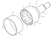
外側継手部材としての外輪3は、図1と図3に示すように、内径面1に複数のトラック溝2が形成されたカップ部12を有する金属製本体15と、この金属製本体15のカップ部12の外径面を被覆するFRP層14とを備えたものである。すなわち、金属製本体15は中炭素鋼等からなり、前記カップ部12と、このカップ部12の底壁12aから突設される軸部13とを備える。
この場合、金属製本体15のカップ部12の外径面16が円筒面とされ、外径面16を円筒状のFRP層14にて被覆している。FRP層14は、合成樹脂剤に浸潤させたFRPをフィラメントワインディング法でマンドレルに巻設して焼き固めてなるFRP製筒体17にて構成している。ここで、FRP(Fiber Reinforced Plastics)とは、繊維でプラスチックを強化したものである。FRPは使用する繊維によって、GFRP(ガラス繊維強化プラスチック)、CFRP(炭素繊維強化プラスチック)、AFRP、KFRP(アラミド繊維強化プラスチック)と呼ばれる。なお、使用する樹脂としては、不飽和ポリエステル樹脂、エポキシ樹脂、フェノール樹脂等の熱硬化性樹脂が代表的であるが、ポリプロピレン、ナイロン、ポリカーボネート等の熱可塑性樹脂も使用できる。
一般に、FRPは次に記載する特性を有する。耐候性、耐熱性、耐薬品性にすぐれている。電気絶縁性があり電波透過性に優れている。断熱性に優れている。さまざまな形状の製作に対応でき、着色が自由である。軽量かつ強度的に優れている。
この場合、FRP層14を構成するFRP製筒体17(図3参照)を成形し、このFRP製筒体17を、金属製本体15のカップ部12の外径面に圧入することになる。FRP製筒体17は、軸線方向に対して+5°~+90°、-5°~-90°の角度で交互に配設される配向角となるように、所定の肉厚となるまで螺旋状に巻設したものである。
金属製本体15のカップ部12の外径面16をFRP層14にて被覆することによって、軽量化を図ることができる。ところで、等速自在継手の外側継手部材の強度は、主に、内径面1に複数のトラック溝2が形成されたカップ部12の外径面16において周方向に働く引張り力である。このため、本発明では、金属製本体15のカップ部12の外径面16をFRP層14にて被覆することによって、このFRP層14にて、外側継手部材に加わる荷重を受けることになる。
次に、図4は、FRP層14の開口端部14aが金属製本体15のカップ部12の開口端18よりも外方へ突出している。このようにFRP層14の開口端部14aが突出することにより、カップ部12のこのようにFRP層14がカップ部12の開口端18を外径側から被うことになって、カップ部12の開口部の拡径を防止できる。このため、強度的に安定したカップ部12を構成することができる。
FRP層14の開口端部14aの突出量A(カップ部12の開口端18とFRP層14の開口端34との寸法)としては、大きすぎると、外輪全体が大型化するとともに、使用するFRPが多くなってコスト高となり、しかも、FRP層14の開口端部14aも損傷し易くなる。また、逆に突出量Aが小さすぎると、カップ部12の開口部の拡径を防止する機能を発揮することができない。このため、金属製本体15のカップ部12及び/又はFRP層14のサイズ、肉厚、材質、等によって相違するが、シャフトが最大作動角を取れる範囲の突出量とすることを前提とし、例えば、3mm~5mm程度とされる。
次に、図5ではFRP層14が、複数個の短FRP層部20(この場合、短FRP層部20A、短FRP層部20B、短FRP層部20C)からなる。短FRP層部20A、20B、20Cは、厚み(肉厚)、巻き方、繊維の種類等が相違する。
例えば、トルクが負荷された際に円周方向に広がろうとするカップ入口端面付近は、繊維の巻き角を80~90degの短FRP層部20Aとすることで拡径方向に対する変形を抑制する。カップ中央部付近は、巻き角45degの短FRP層部20Bとし捩り強度を高める部位とする。肉厚が比較的大きいカップ底付近は、厚さの薄い短FRP層部20Cとする。
このように、出来合いの短FRP層部20を複数個組み合わせる様にすることで、FRP層14を製作する際の巻き角や厚みを途中で変える必要がなくなることから、FRP層14の製作が容易になり、更に最適仕様のFRP層14に容易にチューニングできる。
なお、短FRP層部20を構成するFRPにCFRP(炭素繊維強化プラスチック)を用いた場合、炭素繊維はその繊維の方向に引張り強度が高いため、円周方向に広がろうとする入口付近は90deg方向、捩れやすい部分は捩りの最大主応力方向の45deg方向になるよう炭素繊維を巻くことになる。
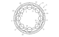
次に図6では、FRP層14の内径面19と金属製本体15のカップ部12の外径面16との間に、軸方向に延びる凸部21と、軸方向に延びて前記凸部21に嵌合する凹部22とを有する凹凸嵌合構造部Mを設ける。
この場合、図7に示すように、FRP層14の内径面19に周方向に沿って45°ピッチで、断面半楕円状の凸部21が4個配設されている。また、金属製本体15のカップ部12の外径面16には、FRP層14の凸部21に嵌合する断面半楕円状の凹部22が周方向に沿って45°ピッチで4個配設されている。
このように、凹凸嵌合構造部Mを設けることによって、金属製本体15とFRP層14との円周方向のずれを抑制することができ、長期にわたって安定した状態(金属製本体15とFRP層14との固定状態)を維持できる。
FRP層14の内径面19に凸部21が形成されたものでは、FRPとして、針状炭素繊維を含有させた樹脂(例えば、熱可塑性樹脂)を用いて、射出成形により形成することができる。
凹凸嵌合構造部Mとして、凸部21を金属製本体15のカップ部12の外径面16に設け、凹部22をFRP層14の内径面19に設けてもよい。しかしながら、凹部22をFRP層14の内径面19に設ければ、FRP層14の体積が減少するとともに、金属製本体15のカップ部12の体積が増加することになって、軽量化効果が少なくなる。また、金属製本体15のカップ部12においては、凹部22を形成する加工よりも凸部21を形成する加工のほうが難しい。
図8では、金属製本体15の外径面16に軸方向に延びる凸部21を形成し、この凸部21をFRP層14の内径部に圧入し、この圧入によって、FRP層14の内径面19に凸部21に嵌合する凹部22を形成して凹凸嵌合構造部Mを構成したものである。
すなわち、金属製本体15の外径面16に、スプライン形状となるように、複数の凸部21を形成して雄スプライン部25を設ける。また、FRP層14を構成するFRP製筒体17の内径面には凹部を形成しないものとする。この場合、凸部21を断面台形状とし、FRP製筒体17の内径面の内径寸法を、この凸部21の頂部を結ぶ円の直径よりも小さくするとともに、金属製本体15の外径面16(凸部21を省いた外径面)の直径寸法と同一乃至金属製本体15の外径面16(凸部21を省いた外径面)よりも大きく設定する。
これによって、金属製本体15の外径面16に、FRP製筒体17を圧入していけば、凸部21がFRP製筒体17の内径部を削りながら圧入されることになる。このため、凸部21と凹部22との接合性に優れ、高品質の外側継手部材を提供できる。
次に図10では、金属製本体15の外径面開口部側に、この種の等速自在継手に装着されるブーツ(図示省略)のブーツ装着用溝26を形成したものである。すなわち、金属製本体15の外径面軸部側に周方向切欠部27を設け、この周方向切欠部27にFRP層14を装着(外嵌)しているものである。周方向切欠部27側の端部には突起部30が設けられ、この突起部30にて、装着されるブーツの位置決めがなされる。
金属製本体にブーツ装着用溝を設けるようにしたものでは、ブーツ装着用溝を加工性に優れた金属(例えば、鋼)に成形することができ、生産性に優れ、しかも、FRPの使用量を抑えることができてコスト低減に寄与する。
次に図11では、外径面32にブーツ装着用溝29を形成したFRP層14を使用したものである。すなわち、金属製本体15のほぼ外径面16の全長にわたる切欠凹部28を設け、この切欠凹部28にブーツ装着用溝29を形成したFRP層14を装着(外嵌)しているものである。なお、FRP層14の開口端部14aの端面が、金属製本体15の開口端18に一致している。また、FRP層14の外径面32には、前記ブーツ装着用溝29以外に、ブーツ位置決め用の突起部30Aが設けられている。また、FRP層14の反開口端33は、切欠凹部28の端面40に当接している。
FRP層14の外径面32にブーツ装着用溝29を設けたものでは、一層の軽量化を図ることができる。
図12では、図12Bに示すように、金属製本体15のカップ部12の開口端18に、外径側へ加締られてFRP層14に係合する加締部35を設けている。すなわち、図12Aに示すように、図11に示す金属製本体15のカップ部12において、その開口端18に突起部36を設け、金属製本体15のカップ部12にFRP層14が装着された状態で、突起部36を外径側へ塑性変形させてFRP層14の開口端34に係合する加締部35を形成する。この場合、FRP層14の反開口端33は、切欠凹部28の端面40に当接し、加締部35とこの端面40とで、FRP層14が挟持された状態となり、このFRP層14の金属製本体15にカップ部12からの抜けを有効に防止できる。
加締部35を構成する突起部36としては、カップ部12の開口端18に周方向の全周にわたるリング体であっても、カップ部12の開口端18に周方向に沿って所定ピッチで複数個が配設されるものであってもよい。
このように、加締部35を設けたものでは、FRP層14の抜けを防止することができ、長期にわたって等速自在継手としての機能を有効に発揮できる。特に、金属製本体15とFRP層14とは材質が相違するので、膨張係数が相違して、FRP層14が金属製本体15に対して遊嵌状となる場合があり、このような場合であっても、加締部によって、FRP層14の抜けを防止することができる。
ところで、前記実施形態では、FRP層14を構成するFRP製筒体17を別途成形して、このFRP製筒体17を金属製本体15の外径面16に圧入するものであったが、金属製本体15の外径面16に直接的にFRPを巻設するものであってもよい。
すなわち、合成樹脂剤に浸潤させたFRPをフィラメントワインディング法又はシートワインディング法にて金属製本体15のカップ部12の外径面16に巻設して、前記FRP層14を構成することになる。
また、前記各実施形態において、金属製本体15のカップ部12とFRP層14との間に接着剤を介在させるようにしてもよい。接着剤としては、金属・樹脂間の接合性の点からエポキシ系やウレタン系等の種々の接着剤を選択できる。
金属製本体15とFRP層14とが接着剤を介して接合したものであれば、FRP層14の金属製本体15のカップ部12への嵌め合い関係を隙間として、この隙間に接着剤を介在させることができる。このため、金属製本体15のカップ部12にFRPを直接巻設しないものであって、FRP層14を別個に成形する場合、FRP層14の内径面19を金属製本体のカップ部の外径面に圧接させる必要がない。すなわち、FRP層14の内径面寸法を高精度に仕上げる必要がなく、生産性に優れる。
FRP層の外径面に保護膜を形成することができる。保護膜としては、例えばウレタン系塗料等を塗布する塗装、または、FRP、CFRPを仕上げに薄く巻いたものを保護膜とするカバー材にて構成することができる。
保護膜を形成することによって、FRP層14の外径面32を保護することができ、FRP層の劣化、飛び石等による打ち傷を防止することができる。
FRPとして、GFRP(ガラス繊維強化プラスチック)、CFRP(炭素繊維強化プラスチック)、AFRP、KFRP(アラミド繊維強化プラスチック)を用いることができ、このように、繊維の種類によって、特性の相違するFRP層を構成することができる。すなわち、GFRPは、材料が安価でいろいろな形状になじみやすいので、様々な反転ができ、形状の自由度が高い。また硬化時間が比較的短いため、短納期で製作できる利点がある。CFRPは、GFRPより高価であるが、強度の面で優れており、積層数を薄くすることによって重さを軽くすることができる。強度を必要とし、なおかつ重量を軽くしたい制作物に向いている。AFRP、KFRPは、切断されにくく、最も優れた強度を発揮する。しかしながら、繊維の持つ切れにくいという特性が、自由な形状の成形を困難にし、後加工がしにくいという面もある。
以上、本発明の実施形態につき説明したが、本発明は前記実施形態に限定されることなく種々の変形が可能であって、例えば、FRP層14の厚さ寸法は、使用される環境、金属製本体15の材質、カップ部12の肉厚等に応じて種々選択できる。また、短FRP層部20を用いる場合、その数の増減は任意であり、各短FRP層部20の軸方向長さや肉厚等も任意に設定できる。凹凸嵌合構造部Mの凹凸の数の増減は任意であり、凹凸嵌合構造部Mを設ける場合の凸部21数として少なくとも1つあればよい。凸部の断面形状としても、半楕円形状や台形形状に限るものではなく、半円形状や半多角形状等であってもよく、各凸部21の大きさも任意に設定できる。また、トラック溝の数としても、その増減は任意である。
等速自在継手としては、トラック溝の溝底全範囲が円弧形状であるバーフィールド型(BJ)であっても、トラック溝の溝底が円弧形状部とストレート形状部とを有するアンダーカットフリー型(UJ)であってもよい。
1 内径面
2 トラック溝
12 カップ部
14 FRP層
15 金属製本体
16 外径面
17 FRP製筒体
18 開口端
19 内径面
20 短FRP層部
20A 短FRP層部
20B 短FRP層部
20C 短FRP層部
21 凸部
22 凹部
26 ブーツ装着用溝
29 ブーツ装着用溝
35 加締部
M 凹凸嵌合構造部
2 トラック溝
12 カップ部
14 FRP層
15 金属製本体
16 外径面
17 FRP製筒体
18 開口端
19 内径面
20 短FRP層部
20A 短FRP層部
20B 短FRP層部
20C 短FRP層部
21 凸部
22 凹部
26 ブーツ装着用溝
29 ブーツ装着用溝
35 加締部
M 凹凸嵌合構造部
Claims (15)
- 内径面に複数のトラック溝が形成された等速自在継手用外側継手部材において、
内径面に複数のトラック溝が形成されたカップ部を有する金属製本体と、この金属製本体のカップ部の外径面を被覆するFRP層とを備えたことを特徴とする等速自在継手用外側継手部材。 - 合成樹脂剤に浸潤させたFRPをフィラメントワインディング法でマンドレルに巻設して焼き固めてなるFRP製筒体にて、前記FRP層を構成したことを特徴とする請求項1に記載の等速自在継手用外側継手部材。
- 合成樹脂剤に浸潤させたFRPをフィラメントワインディング法又はシートワインディング法にて前記金属製本体のカップ部の外径面に巻設して、前記FRP層を構成したことを特徴とする請求項1に記載の等速自在継手用外側継手部材。
- 前記FRP層が軸線方向に対して+5°~+90°、-5°~-90°の角度で交互に配設される配向角となるように、所定の肉厚となるまで螺旋状に巻設したことを特徴とする請求項1~請求項3のいずれか1項に記載の等速自在継手用外側継手部材。
- 前記FRP層が、金属製本体のカップ部の開口端よりも外方へ突出していることを特徴とする請求項1~請求項4のいずれか1項に記載の等速自在継手用外側継手部材。
- FRP層は、複数種類の短FRP層部からなることを特徴とする請求項1、請求項2、又は請求項5のいずれか1項に記載の等速自在継手用外側継手部材。
- 前記FRP層の内径面と前記金属製本体のカップ部の外径面との間に、軸方向に延びる凸部と、軸方向に延びて前記凸部に嵌合する凹部とを有する凹凸嵌合構造部を設けたことを特徴とする請求項1、請求項2、請求項5、又は請求項6のいずれか1項に記載の等速自在継手用外側継手部材。
- 前記金属製本体の外径面に軸方向に延びる凸部を形成し、この凸部を前記FRP層の内径部に圧入し、この圧入によって、FRP層の内径面に前記凸部に嵌合する凹部を形成して前記凹凸嵌合構造部を構成したことを特徴とする請求項7に記載の等速自在継手用外側継手部材。
- 前記金属製本体のカップ部の開口側の外径面にブーツ装着用溝を形成するとともに、ブーツ装着用溝よりも反開口側の外径面に、前記FRP層の嵌合用の切欠部を設けたことを特徴とする請求項1~請求項4、又は請求項6~請求項8のいずれか1項に記載の等速自在継手用外側継手部材。
- 前記FRP層の外径面にブーツ装着用溝を設けたことを特徴とする請求項1~請求項8のいずれか1項に記載の等速自在継手用外側継手部材。
- 前記金属製本体のカップ部の開口端に、外径側へ加締られて前記FRP層に係合する加締部を設けたことを特徴とする請求項1~請求項4、請求項6~請求項8、又は請求項10のいずれか1項に記載の等速自在継手用外側継手部材。
- 前記金属製本体と前記FRP層とが接着剤を介して接合したことを特徴とする請求項1~請求項11のいずれか1項に記載の等速自在継手用外側継手部材。
- 前記FRP層の外径面に保護膜を形成したことを特徴とする請求項1~請求項12のいずれか1項に記載の等速自在継手用外側継手部材。
- 前記FRP層はCFRPであることを特徴とする請求項1~請求項13のいずれか1項に記載の等速自在継手用外側継手部材。
- 前記FRP層を射出成形により成形したしたことを特徴とする請求項14に記載の等速自在継手用外側継手部材。
Applications Claiming Priority (2)
| Application Number | Priority Date | Filing Date | Title |
|---|---|---|---|
| JP2008-300877 | 2008-11-26 | ||
| JP2008300877A JP2010127339A (ja) | 2008-11-26 | 2008-11-26 | 等速自在継手用外側継手部材 |
Publications (1)
| Publication Number | Publication Date |
|---|---|
| WO2010061707A1 true WO2010061707A1 (ja) | 2010-06-03 |
Family
ID=42225588
Family Applications (1)
| Application Number | Title | Priority Date | Filing Date |
|---|---|---|---|
| PCT/JP2009/068448 Ceased WO2010061707A1 (ja) | 2008-11-26 | 2009-10-28 | 等速自在継手用外側継手部材 |
Country Status (2)
| Country | Link |
|---|---|
| JP (1) | JP2010127339A (ja) |
| WO (1) | WO2010061707A1 (ja) |
Cited By (3)
| Publication number | Priority date | Publication date | Assignee | Title |
|---|---|---|---|---|
| WO2010099867A3 (de) * | 2009-03-02 | 2010-11-04 | Volkswagen Aktiengesellschaft | Gleichlauffestgelenk |
| JP2012096306A (ja) * | 2010-10-29 | 2012-05-24 | Kitagawa Iron Works Co Ltd | 高剛性チャック及びその製造方法 |
| JP2014066348A (ja) * | 2012-09-27 | 2014-04-17 | Nsk Ltd | スピンドル装置及びスピンドル装置用フリンガー |
Families Citing this family (2)
| Publication number | Priority date | Publication date | Assignee | Title |
|---|---|---|---|---|
| JP5864892B2 (ja) | 2010-06-02 | 2016-02-17 | キヤノン株式会社 | X線導波路 |
| KR101820353B1 (ko) * | 2016-07-12 | 2018-01-19 | 서한산업(주) | 등속 조인트용 외륜 |
Citations (11)
| Publication number | Priority date | Publication date | Assignee | Title |
|---|---|---|---|---|
| JPS5834233A (ja) * | 1981-08-20 | 1983-02-28 | Matsushita Electric Ind Co Ltd | 回転軸の連結装置 |
| JPH02229917A (ja) * | 1988-03-28 | 1990-09-12 | Glaenzer Spicer Sa | 伝動連結装置のボデーおよびその製造方法 |
| JPH03249429A (ja) * | 1990-02-27 | 1991-11-07 | Ntn Corp | 動力伝達軸 |
| JPH09159070A (ja) * | 1995-12-07 | 1997-06-17 | Nitto Denko Corp | 通信アンテナカバー用ガラス繊維強化プラスチック製パイプ |
| JPH10169666A (ja) * | 1996-12-04 | 1998-06-23 | Ntn Corp | ドライブシャフト |
| JPH1178564A (ja) * | 1997-09-12 | 1999-03-23 | Mitsubishi Motors Corp | プロペラシャフト |
| JP2001263329A (ja) * | 2000-03-21 | 2001-09-26 | Toyoda Mach Works Ltd | ドライブシャフトの中間軸 |
| JP2004036813A (ja) * | 2002-07-05 | 2004-02-05 | Nsk Ltd | 車輪駆動用軸受ユニット及びその組立方法 |
| JP2006183728A (ja) * | 2004-12-27 | 2006-07-13 | Toray Ind Inc | プロペラシャフト |
| JP2007056949A (ja) * | 2005-08-23 | 2007-03-08 | Ntn Corp | 等速自在継手用フレキシブルブーツ |
| JP2007327508A (ja) * | 2006-06-06 | 2007-12-20 | Ntn Corp | 車輪用軸受装置 |
-
2008
- 2008-11-26 JP JP2008300877A patent/JP2010127339A/ja active Pending
-
2009
- 2009-10-28 WO PCT/JP2009/068448 patent/WO2010061707A1/ja not_active Ceased
Patent Citations (11)
| Publication number | Priority date | Publication date | Assignee | Title |
|---|---|---|---|---|
| JPS5834233A (ja) * | 1981-08-20 | 1983-02-28 | Matsushita Electric Ind Co Ltd | 回転軸の連結装置 |
| JPH02229917A (ja) * | 1988-03-28 | 1990-09-12 | Glaenzer Spicer Sa | 伝動連結装置のボデーおよびその製造方法 |
| JPH03249429A (ja) * | 1990-02-27 | 1991-11-07 | Ntn Corp | 動力伝達軸 |
| JPH09159070A (ja) * | 1995-12-07 | 1997-06-17 | Nitto Denko Corp | 通信アンテナカバー用ガラス繊維強化プラスチック製パイプ |
| JPH10169666A (ja) * | 1996-12-04 | 1998-06-23 | Ntn Corp | ドライブシャフト |
| JPH1178564A (ja) * | 1997-09-12 | 1999-03-23 | Mitsubishi Motors Corp | プロペラシャフト |
| JP2001263329A (ja) * | 2000-03-21 | 2001-09-26 | Toyoda Mach Works Ltd | ドライブシャフトの中間軸 |
| JP2004036813A (ja) * | 2002-07-05 | 2004-02-05 | Nsk Ltd | 車輪駆動用軸受ユニット及びその組立方法 |
| JP2006183728A (ja) * | 2004-12-27 | 2006-07-13 | Toray Ind Inc | プロペラシャフト |
| JP2007056949A (ja) * | 2005-08-23 | 2007-03-08 | Ntn Corp | 等速自在継手用フレキシブルブーツ |
| JP2007327508A (ja) * | 2006-06-06 | 2007-12-20 | Ntn Corp | 車輪用軸受装置 |
Cited By (3)
| Publication number | Priority date | Publication date | Assignee | Title |
|---|---|---|---|---|
| WO2010099867A3 (de) * | 2009-03-02 | 2010-11-04 | Volkswagen Aktiengesellschaft | Gleichlauffestgelenk |
| JP2012096306A (ja) * | 2010-10-29 | 2012-05-24 | Kitagawa Iron Works Co Ltd | 高剛性チャック及びその製造方法 |
| JP2014066348A (ja) * | 2012-09-27 | 2014-04-17 | Nsk Ltd | スピンドル装置及びスピンドル装置用フリンガー |
Also Published As
| Publication number | Publication date |
|---|---|
| JP2010127339A (ja) | 2010-06-10 |
Similar Documents
| Publication | Publication Date | Title |
|---|---|---|
| JP4846103B2 (ja) | 繊維強化樹脂パイプ及びこれを用いた動力伝達シャフト | |
| US5851152A (en) | Drive shaft with reinforced plastic tube and a joint-connecting body connected nonrotatably endwise | |
| WO2010061707A1 (ja) | 等速自在継手用外側継手部材 | |
| EP0788586A1 (en) | Joint between two components | |
| JP2011226589A (ja) | トリポード型等速自在継手およびトリポード型等速自在継手の外側継手部材 | |
| JP6559414B2 (ja) | 動力伝達シャフト | |
| US20170227045A1 (en) | Connecting shaft and manufacturing method of connecting shaft | |
| US8459978B2 (en) | Method for manufacturing a composite drive shaft manufactured using mold | |
| WO2018178631A1 (en) | Assembling a drive shaft by joining an end fitting to a tube of composite material | |
| JP2011017413A (ja) | 動力伝達軸用シャフト | |
| US12123460B2 (en) | Power transmission shaft | |
| JP2007271079A (ja) | トルク伝達軸 | |
| KR101523617B1 (ko) | 탄소섬유 강화 플라스틱을 적용한 드라이브 샤프트 어셈블리 | |
| JP2011017414A (ja) | 動力伝達軸用シャフト | |
| JP2620607B2 (ja) | 繊維強化樹脂製ドライブシャフトおよびその製造方法 | |
| CN112638689B (zh) | 用于传动轴的管体和传动轴 | |
| US20050143208A1 (en) | Pulley | |
| EP1338822B1 (en) | Manufacturing method for dynamic damper | |
| JP7264665B2 (ja) | 動力伝達軸 | |
| JP2011185281A (ja) | 等速自在継手用外側継手部材および等速自在継手 | |
| KR20170123526A (ko) | 장축커플링 | |
| JPH05180234A (ja) | Frp製パイプのかしめ接合構造 | |
| JP6522356B2 (ja) | 動力伝達シャフト | |
| JP2696307B2 (ja) | 軸継手 | |
| US20100144453A1 (en) | Connection joint and composite drive shaft assembly having them |
Legal Events
| Date | Code | Title | Description |
|---|---|---|---|
| 121 | Ep: the epo has been informed by wipo that ep was designated in this application |
Ref document number: 09828956 Country of ref document: EP Kind code of ref document: A1 |
|
| NENP | Non-entry into the national phase |
Ref country code: DE |
|
| 122 | Ep: pct application non-entry in european phase |
Ref document number: 09828956 Country of ref document: EP Kind code of ref document: A1 |