WO2010058665A1 - 空気調和機 - Google Patents
空気調和機 Download PDFInfo
- Publication number
- WO2010058665A1 WO2010058665A1 PCT/JP2009/067725 JP2009067725W WO2010058665A1 WO 2010058665 A1 WO2010058665 A1 WO 2010058665A1 JP 2009067725 W JP2009067725 W JP 2009067725W WO 2010058665 A1 WO2010058665 A1 WO 2010058665A1
- Authority
- WO
- WIPO (PCT)
- Prior art keywords
- horizontal flap
- diffuser
- air conditioner
- horizontal
- flap
- Prior art date
- Legal status (The legal status is an assumption and is not a legal conclusion. Google has not performed a legal analysis and makes no representation as to the accuracy of the status listed.)
- Ceased
Links
Images







Classifications
-
- F—MECHANICAL ENGINEERING; LIGHTING; HEATING; WEAPONS; BLASTING
- F24—HEATING; RANGES; VENTILATING
- F24F—AIR-CONDITIONING; AIR-HUMIDIFICATION; VENTILATION; USE OF AIR CURRENTS FOR SCREENING
- F24F11/00—Control or safety arrangements
- F24F11/70—Control systems characterised by their outputs; Constructional details thereof
- F24F11/72—Control systems characterised by their outputs; Constructional details thereof for controlling the supply of treated air, e.g. its pressure
- F24F11/79—Control systems characterised by their outputs; Constructional details thereof for controlling the supply of treated air, e.g. its pressure for controlling the direction of the supplied air
-
- F—MECHANICAL ENGINEERING; LIGHTING; HEATING; WEAPONS; BLASTING
- F24—HEATING; RANGES; VENTILATING
- F24F—AIR-CONDITIONING; AIR-HUMIDIFICATION; VENTILATION; USE OF AIR CURRENTS FOR SCREENING
- F24F1/00—Room units for air-conditioning, e.g. separate or self-contained units or units receiving primary air from a central station
- F24F1/0007—Indoor units, e.g. fan coil units
- F24F1/0043—Indoor units, e.g. fan coil units characterised by mounting arrangements
- F24F1/0057—Indoor units, e.g. fan coil units characterised by mounting arrangements mounted in or on a wall
-
- F—MECHANICAL ENGINEERING; LIGHTING; HEATING; WEAPONS; BLASTING
- F24—HEATING; RANGES; VENTILATING
- F24F—AIR-CONDITIONING; AIR-HUMIDIFICATION; VENTILATION; USE OF AIR CURRENTS FOR SCREENING
- F24F1/00—Room units for air-conditioning, e.g. separate or self-contained units or units receiving primary air from a central station
- F24F1/0007—Indoor units, e.g. fan coil units
- F24F1/0059—Indoor units, e.g. fan coil units characterised by heat exchangers
- F24F1/0063—Indoor units, e.g. fan coil units characterised by heat exchangers by the mounting or arrangement of the heat exchangers
Definitions
- This invention relates to an air conditioner.
- an air conditioner As an air conditioner, a horizontal flap disposed at the outlet, a diffuser disposed below the horizontal flap of the outlet, and an auxiliary vertical wind direction plate disposed above the horizontal flap of the outlet. Some are provided (for example, see Japanese Patent Application Laid-Open No. 2007-93092 (Patent Document 1)).
- Patent Document 1 Japanese Patent Application Laid-Open No. 2007-93092
- the horizontal flap, the diffuser, and the auxiliary up-and-down wind direction plate are all directed forward, and the cool air is blown out horizontally, while during the heating operation, the horizontal flap, the diffuser, and the auxiliary up-and-down air direction plate are both lowered Blow the warm air downwards.
- the air conditioner has a problem in that the blown air flow is diffused because the diffuser and the auxiliary up-and-down wind direction plate do not swing simultaneously during the cooling operation or the heating operation during the swing operation of the horizontal flap.
- an object of the present invention is to provide an air conditioner that can swing the blowing direction up and down while suppressing the diffusion of the blowing air flow in the swing operation of the horizontal flap during the cooling operation or the heating operation.
- the air conditioner of the present invention is A diffuser that is rotatably supported on the upper side of the outlet passage, and whose lower surface forms part of the upper side of the outlet passage; A horizontal flap rotatably supported on the lower side of the diffuser in the outlet passage; The diffuser and the controller for controlling the horizontal flap are provided so that the diffuser has a region that swings simultaneously with the horizontal flap.
- the diffuser is provided on the wall surface of the blowout passage and allows the shape of the flow path to be changed.
- the diffuser may have a flap shape or a triangular prism shape in cross section. Also good.
- the diffuser that is rotatably supported on the upper side of the blowing passage and whose lower surface forms a part of the upper side of the blowing passage is provided on the blowing passage.
- the control unit controls the diffuser and the horizontal flap so that it has an area that swings simultaneously with the horizontal flap that is pivotally supported on the lower side of the diffuser, thereby controlling the blow direction while suppressing the diffusion of the blown air flow. Can swing up and down.
- the control unit has a region where the diffuser and the horizontal flap swing simultaneously so that the blown air flow is directed forward during the cooling operation, and the blower air flow is directed downward during the heating operation.
- the diffuser and the horizontal flap are controlled so that the diffuser and the horizontal flap have a region where the swing operation is performed simultaneously.
- the air flow is directed forward during the cooling operation, and the diffuser and the horizontal flap simultaneously swing, so that the cool air can be sent to a wide space in the front room and the heating operation is performed.
- the diffuser and the horizontal flap swing simultaneously with the air flow directed downward warm air can be sent to a large space near the floor surface in the room.
- the diffuser When the horizontal flap is rotated upward from the bottom dead center of the swing operation in the swing operation, the diffuser is in a state along the upper surface of the blowing passage and is rotated before the horizontal flap.
- the diffuser and the horizontal flap are controlled so as to stop.
- the diffuser when the horizontal flap rotates upward from the bottom dead center of the swing operation in the swing operation, the diffuser is in a state along the upper surface of the outlet passage and stops rotating before the horizontal flap.
- the swing operation of the diffuser interlocked with the horizontal flap can be performed without a sense of incongruity according to the shape of the blowout passage.
- the control unit rotates the horizontal flap downward from the top dead center of the swing operation in the swing operation, the diffuser in a state along the upper surface of the outlet passage rotates downward with a delay from the horizontal flap.
- the diffuser and the horizontal flap are controlled as described above.
- the diffuser in a state along the upper surface of the blowing passage rotates downward with a delay from the horizontal flap.
- the swing operation of the diffuser linked to the horizontal flap can be performed without a sense of incongruity.
- the diffuser When the horizontal flap is at a rotational position where the air resistance of the horizontal flap with respect to the blown air flow in the blowout passage is substantially minimum, the diffuser is in a state along the upper surface of the blowout passage. The diffuser and the horizontal flap are controlled so that they are stopped.
- the diffuser when there is a horizontal flap at a rotational position where the air resistance of the horizontal flap to the blown air flow in the blowout passage is substantially minimum, the diffuser is stopped in a state along the upper surface of the blowout passage.
- the diffuser it is possible to reduce the resistance loss due to the diffuser in the blowing passage and blow out with the maximum air volume.
- the control unit sets the rotation position at which the air resistance of the horizontal flap is substantially minimum as the bottom dead center and Swing in the area between top dead center.
- the control unit sets the rotation position at which the air resistance of the horizontal flap is substantially minimum as the top dead center and Swing in the area between the bottom dead center.
- the control unit controls the diffuser and the horizontal flap so that a lower surface of the diffuser and a blade surface of the horizontal flap are substantially parallel to each other in at least a part of a region where the swing operation is performed.
- the diffusion of the blown air flow is reliably suppressed by performing the swing operation so that the lower surface of the diffuser and the blade surface of the horizontal flap are substantially parallel in at least a part of the region where the swing operation is performed. be able to.
- the control unit rotates the diffuser at a lower angular velocity than the horizontal flap while rotating upward.
- the diffuser and the horizontal flap are controlled so as not to interfere with each other by making the rotation speed of the horizontal flap slower than that of the diffuser.
- the control unit when the control unit is rotated downward in a region other than the region where the diffuser and the horizontal flap simultaneously swing, the rotational angular velocity of the diffuser is slower than that of the horizontal flap, but the upward rotation is performed.
- the rotation speed of the horizontal flap In order to prevent the diffuser and the horizontal flap from interfering with each other by making the rotation speed of the horizontal flap slower than that of the diffuser, it is possible to eliminate the generation of abnormal noise and the uncomfortable appearance and to prevent failure.
- the control unit In the region other than the region where the diffuser and the horizontal flap swing simultaneously, the control unit, when rotating downward from the top dead center, by delaying the rotation start of the diffuser than the horizontal flap, The diffuser and the horizontal flap are controlled so as not to interfere with each other.
- the rotation start of the diffuser is made slower than the horizontal flap. Since the diffuser and the horizontal flap are prevented from interfering with each other, the generation of abnormal noise and the uncomfortable appearance are eliminated, and failure can be prevented.
- the air conditioner of the present invention in the swing operation of the horizontal flap during the cooling operation or the heating operation, the air that can swing the blown air flow up and down while suppressing the diffusion of the blown air flow A harmony machine can be realized.
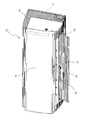
- FIG. 1 is a perspective view of an air conditioner according to an embodiment of the present invention as viewed obliquely from below.
- FIG. 2 is a perspective view of the air conditioner as seen from an obliquely lower side than FIG.
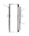
- FIG. 3 is a front view of the air conditioner.
- FIG. 4 is a cross-sectional view of the air conditioner as viewed from line IV-IV in FIG.
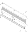
- FIG. 5 is an exploded perspective view of the diffuser and the first and second horizontal flaps of the air conditioner.
- FIG. 6 is a cross-sectional view of the air conditioner in a stopped state.
- FIG. 7 is a cross-sectional view of the air conditioner during cooling operation.
- FIG. 8 is a front view of a state in which the diffuser is lowered during the heating operation of the air conditioner.
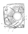
- FIG. 9 is a block diagram of a main part of the air conditioner.
- FIG. 10A is a diagram for explaining a swing operation during the cooling operation of the air conditioner.
- FIG. 10B is a diagram for explaining a swing operation during the cooling operation of the air conditioner.
- FIG. 10C is a diagram for explaining a swing operation during the cooling operation of the air conditioner.
- FIG. 11A is a diagram for explaining a swing operation during the heating operation of the air conditioner.
- FIG. 11B is a diagram for explaining a swing operation during the heating operation of the air conditioner.
- FIG. 11C is a diagram for explaining a swing operation during the heating operation of the air conditioner.
- FIG. 12 is a timing chart when the swing operation of the diffuser and the first and second horizontal flaps is started.
- FIG. 13 is a timing chart when the swing operation is started from the fully closed state of the diffuser and the first and second horizontal flaps.
- FIG. 14 is a timing chart when the swing operation of the diffuser and the first and second
- FIG. 1 shows a perspective view of an air conditioner according to an embodiment of the present invention as seen from an obliquely lower side
- FIG. 2 shows a perspective view of the air conditioner as seen from an obliquely lower side than FIG. Yes.
- the air conditioner is a wall-mounted type that is attached to a wall surface in a room, but may be another form of air conditioner.
- the air conditioner includes a front grill 12 that is detachably attached to the front side of the bottom frame 11, and a front panel that is detachably attached to the front side of the front grill 12. 13.
- the bottom frame 11, the front grill 12 and the front panel 13 constitute a casing 10.
- a first horizontal flap 21 having a blade length that can substantially cover the air outlet 20 is rotatably supported by a horizontally long rectangular air outlet 20 provided at the lower front side of the casing 10. Further, a second horizontal flap 22 having a blade length shorter than that of the first horizontal flap 21 and at least a part of which overlaps the first horizontal flap 21 is rotated below the outlet 20 of the casing 10 and the first horizontal flap 21. Supports freely. Furthermore, the diffuser 23 is rotatably supported above the blowout passage 33 from the blower fan 32 (shown in FIG. 4) to the blowout port 20.
- the “wing length” is the distance between the blades in the wind flow direction.
- FIG. 1 and FIG. 2 show a state during heating operation in which the first and second horizontal flaps 21 and 22 and the diffuser 23 are all rotated downward and the blown airflow is directed downward.
- FIG. 3 shows a front view of the air conditioner
- FIG. 4 shows a cross-sectional view taken along line IV-IV in FIG.
- the first horizontal flap 21 and the diffuser 23 out of the first and second horizontal flaps 21 and 22 and the diffuser 23 are visible, and the second horizontal flap 22 is hidden behind the first horizontal flap 21 and cannot be seen.
- an indoor heat exchanger 31 having a U-shaped cross section is disposed in the casing 10 and on the front side of the bottom frame 11, and a blower fan 32 is disposed below the indoor heat exchanger 31. is doing.
- the blower fan 32 is a cross flow fan arranged so that the rotation axis is in the horizontal direction.
- An outlet passage 33 is formed between the blower fan 32 and the outlet 20.
- first horizontal flap 21 and the second horizontal flap 22 are rotatably supported by one support arm 24 provided substantially at the center of the air outlet 20 of the casing 10.
- An air passage 34 is provided between the lower edge of the air outlet 20 and the second horizontal flap 22.
- a diffuser 23 is rotatably supported above the blower outlet 20 and the first horizontal flap 21.
- a plurality of vertical flaps 25 are arranged at predetermined intervals in the left-right direction at the air outlet 20 of the casing 10.
- the plurality of vertical flaps 25 are connected via a drive arm (not shown), and the plurality of vertical flaps 25 rotate in the left-right direction in accordance with the sliding movement of the drive arm, so that the air direction of the blown air is changed to the left and right. Control.
- the blower fan 32 when the blower fan 32 is driven by a fan motor (not shown), indoor air is sucked through the suction port 12a on the upper surface side of the front grill 12 and the suction port 13a on the upper end side of the front panel 13. . Then, the sucked room air passes through the indoor heat exchanger 31 and is heat-exchanged, and then blown out from the blower outlet 20 into the room through the blowout passage 33 by the blower fan 32.
- FIG. 5 is an exploded perspective view of the first and second horizontal flaps 21 and 22 and the diffuser 23 of the air conditioner.
- the first horizontal flap 21 has a rectangular shape with a long horizontal direction.
- the lower side of the first horizontal flap 21 is the leeward wing tip, and the upper side is the leeward wing tip.
- the center of rotation of the first horizontal flap 21 is set so that the windward side is above the blade tip (lower side in FIG. 5) and substantially parallel to the blade tip.
- the first horizontal flap 21 includes a central shaft portion 41 provided substantially at the center, a left shaft portion 42 provided on the left side, and a right bearing portion 43 provided on the right side along the rotation center. I have. Further, on the left side of the central shaft portion 41 of the first horizontal flap 21, a substantially rectangular support arm interference prevention cut-out portion 21 a having an upwind side is provided.
- a substantially rectangular second horizontal flap interference prevention which is smaller than the support arm interference prevention cutout portion 21a and is continuous with the support arm interference prevention cutout portion 21a.
- a notch 21b for use is provided.
- a substantially rectangular second horizontal flap interference-preventing cutout 21c is provided in the vicinity of the left shaft portion 42 of the first horizontal flap 21, and a substantially rectangular second horizontal flap in the vicinity of the right bearing portion 43 of the first horizontal flap 21.
- a notch 21d for preventing interference is provided.
- the first horizontal flap 21 rotates in the vertical direction when a drive shaft (not shown) provided on the right side surface of the air outlet 20 rotates.
- the second horizontal flap 22 has a rectangular shape with a long horizontal direction.
- the lower side of the second horizontal flap 22 is the leeward wing tip
- the upper side is the leeward wing tip.
- the rotation center of the second horizontal flap 22 is set in the vicinity of the windward blade tip (lower side in FIG. 5) and substantially parallel to a straight line along the blade tip.
- the second horizontal flap 22 includes a central shaft portion 51 provided substantially at the center, a left shaft portion 52 provided on the left side, and a right bearing portion 53 provided on the right side along the rotation center. I have.
- the second horizontal flap 22 rotates in the vertical direction when a drive shaft (not shown) provided on the right side surface of the air outlet 20 rotates.
- the diffuser 23 has a central shaft portion 61 provided substantially at the center, a left shaft portion 62 provided on the left side, and a right side provided on the right side along the rotation center. And a bearing portion 63.
- the diffuser 23 rotates in the vertical direction when a drive shaft (not shown) provided on the right side surface of the air outlet 20 rotates.
- FIG. 6 shows a cross-sectional view of the air conditioner in a stopped state (a state where the air outlet 20 is closed).
- the first horizontal flap 21 has a blade length that can substantially cover the air outlet 20
- the second horizontal flap 22 has a blade length shorter than that of the first horizontal flap 21.
- the second horizontal flap 22 is the first horizontal flap except for a part on the windward side. It overlaps with 21.
- the second horizontal flap 22 overlaps the wing portion on the windward side of the first horizontal flap 21, and the lower wing surface of the second horizontal flap 22 and the lower wing surface of the leeward side wing portion of the first horizontal flap 21 are stepless. It has come to be connected.
- the diffuser 23 is in a state where the upper blade surface is substantially in contact with the upper wall surface of the blowing passage 33, and this state is a fully closed state of the diffuser 23.
- FIG. 7 shows a cross-sectional view of the air conditioner during cooling operation.
- the first horizontal flap 21 and the second horizontal flap 22 are rotated so as to be substantially horizontal, and the second horizontal flap with respect to the blade surface of the first horizontal flap 21.
- the wing surfaces of 22 are made substantially parallel.
- the first horizontal flap 21 is overlapped with an interval, except for a part of the windward side of the second horizontal flap 22.
- the cold air from the blower fan 32 is blown out from the blower outlet 20 in the substantially horizontal direction through the blowout passage 33 by the first horizontal flap 21 and the second horizontal flap 22.
- the diffuser 23 is in a state where the upper wing surface is in contact with the upper wall surface of the blowing passage 33.
- the protrusion 35 on the upper wall surface of the blow-out passage 33 is covered with a recess 23 a provided at a position corresponding to the protrusion 35 of the diffuser 23, thereby preventing the air flow in the blow-out passage 33 from being disturbed by the protrusion 35. ing.
- the diffuser 23 is in a state where the upper blade surface is substantially in contact with the upper wall surface of the outlet passage 33, but the first and second horizontal flaps 21, 22 are rotated in the same state.
- the lower surface of the diffuser 23 and the upper blade surface of the first horizontal flap 21 may be gradually narrowed toward the downstream. As a result, the speed of the blown airflow is increased so that the cold air reaches a farther place.
- FIG. 8 shows a cross-sectional view of the state in which the diffuser 23 is lowered during the heating operation of the air conditioner.
- the first horizontal flap 21 and the second horizontal flap 22 are rotated so as to tilt obliquely downward, and the second horizontal flap with respect to the blade surface of the first horizontal flap 21.
- the wing surfaces of 22 are made substantially parallel.
- the second horizontal flap 22 overlaps the first horizontal flap 21 with an interval.
- the diffuser 23 rotates so that it may incline in the diagonally downward direction, and the air flow which flows through the upper side of the blowing passage 33 is directed below by the diffuser 23, warm air from the blower outlet 20 does not flow upwards, but it is a step. Hot air can be blown out effectively. At this time, the protrusion 35 is shielded by the recess 23a of the diffuser 23 and does not affect the airflow.
- FIG. 9 shows a block diagram of the main part of the air conditioner.
- the air conditioner includes a control unit 100 including a microcomputer and an input / output circuit.
- the air conditioner includes a diffuser drive motor 101 that drives the diffuser 23, a first horizontal flap drive motor 102 that drives the first horizontal flap 21, and a second horizontal flap drive motor that drives the second horizontal flap 22. 103, a temperature sensor 104 for detecting the room temperature, a fan motor 105 for driving the blower fan 32 (shown in FIG. 4), and a display unit 106 for displaying an operation state and the like.
- Stepper motors are used as the diffuser drive motor 101, the first horizontal flap drive motor 102, and the second horizontal flap drive motor 103.
- the control unit 100 includes a diffuser drive motor 101, a first horizontal flap drive motor 102, a second horizontal flap drive motor 103, a fan motor 105, a display unit 106, and the like based on the room temperature detected by the temperature sensor 104. Control.
- the control unit 100 controls the diffuser drive motor 101, the first horizontal flap drive motor 102, and the second horizontal flap drive motor 103, and the diffuser 23 and the first horizontal flap drive motor 103 in a swing range corresponding to an operation mode such as cooling operation or heating operation.
- the first and second horizontal flaps 21 and 22 are simultaneously swung.
- FIG. 10A to 10C show the swing operation during the cooling operation of the air conditioner, and FIG. 10A shows the state when the first horizontal flap 21 is at the top dead center P1 of the swing operation region S1, 10B shows a state when the first horizontal flap 21 is at the maximum air volume position P3 of the swing operation region S1, and FIG. 10C shows a state when the first horizontal flap 21 is at the bottom dead center P2 of the swing operation region S1. Is shown.
- the second horizontal flap 22 swings in the range of the region S2 in accordance with the swing operation of the first horizontal flap 21, and in accordance with the swing operation of the first horizontal flap 21,
- the diffuser 23 swings in the area S3.
- the diffuser 23 when the first horizontal flap 21 is at the top dead center P1 of the swing operation region S1, the diffuser 23 is in a fully closed state in which the upper blade surface is substantially in contact with the upper wall surface of the blowing passage 33.
- the diffuser. 23 begins to rotate downward.
- the second horizontal flap is set so that the blade surface facing the blade surface of the first horizontal flap 21 is substantially parallel.
- the diffuser 23 is rotated so that the lower blade surface facing the blade surface of the first horizontal flap 21 is substantially parallel.
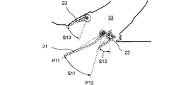
- FIG. 11A to 11C show a swing operation during the heating operation of the air conditioner, and FIG. 11A shows a state when the first horizontal flap 21 is at the top dead center P11 of the swing operation region S11.
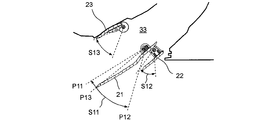
- 11B shows a state when the first horizontal flap 21 is at the maximum air volume position P13 of the swing operation region S11
- FIG. 11C shows a state when the first horizontal flap 21 is at the bottom dead center P12 of the swing operation region S11. Shows the state.
- the second horizontal flap 22 swings in the range of the region S12 in accordance with the swing operation of the first horizontal flap 21, and in accordance with the swing operation of the first horizontal flap 21,
- the diffuser 23 swings in the area S13.
- the diffuser 23 when the first horizontal flap 21 is at the top dead center P11 of the swing operation region S11, the diffuser 23 is in a fully closed state in which the upper blade surface is substantially in contact with the upper wall surface of the blowing passage 33.
- the second horizontal flap is set so that the blade surface facing the blade surface of the first horizontal flap 21 is substantially parallel.
- the diffuser 23 is rotated so that the lower blade surface facing the blade surface of the first horizontal flap 21 is substantially parallel.
- the diffuser 23 in the region from the top dead center P11 where the first horizontal flap 21 rotates to the maximum airflow position P13, the diffuser 23 is in a fully closed state in which the upper wing surface is substantially in contact with the upper wall surface of the blowing passage 33.
- the range of the swing operation of the first horizontal flap 21 is not limited to the regions S1 and S11 during the cooling operation of FIGS. 10A to 10C and the heating operation of FIGS. 11A to 11C, but depends on the operation state and the operation mode. Set as appropriate.
- the rotation position where the air resistance of the first horizontal flap 21 is substantially minimum is set as the bottom dead center, and the bottom dead center and the upper Swing operation may be performed in the region between the top dead center and when the swing operation is performed simultaneously with the diffuser 23 during the heating operation, the rotational position where the air resistance of the first horizontal flap 21 is substantially minimum is top dead.
- a swing operation may be performed in a region between the top dead center and the bottom bottom dead center.
- FIGS. 12 (a) to 12 (c) show timing charts when the swing operation of the diffuser 23 and the first and second horizontal flaps 21 and 22 is started.
- the fully closed position of the diffuser 23 is a position where the upper wing surface is substantially in contact with the upper wall surface of the blowing passage 33, and the fully opened position of the diffuser 23 is lower than the bottom dead center of the region S13 in FIGS. 11A to 11C. It is a position where the diffuser 23 further rotates downward and stops when it hits a structure (not shown).
- the fully closed position of the 1st horizontal flap 21 is a position which covers the blower outlet 20 and the 1st horizontal flap 21 hits a structure (for example, front panel above the blower outlet 20), and stops as shown in FIG. Yes, the fully opened position of the first horizontal flap 21 rotates further downward from the bottom dead center P12 of the region S11 in FIGS. 11A to 11C, and the first horizontal flap 21 hits a structure (not shown) and stops. It is a position to do.
- the fully closed position of the second horizontal flap 22 is a position where the second horizontal flap 22 hits the structure (the first horizontal flap 21 in the fully closed state) and stops, and the second horizontal flap 22
- the fully open position 22 is a position where the second horizontal flap 22 hits a structure (not shown) and stops by rotating further downward from the bottom dead center of the region S12 in FIGS. 11A to 11C.
- the rotational angular velocity of the diffuser 23 between the times t2 and t3 is based on the time (t3-t2) for the first horizontal flap 21 to reach the bottom dead center, and the diffuser 23 is simultaneously with the first horizontal flap 21. Set to reach bottom dead center.
- the rotational angular velocity of the diffuser 23 between the times t4 and t5 is based on the time (t5-t4) for the first horizontal flap 21 to reach the maximum airflow position, so that the first horizontal flap 21 is at the maximum airflow position.
- the diffuser 23 is set to reach the fully closed position.
- the first and second horizontal flaps 21 and 22 rotate upward to reach the swing upper limit position (top dead center) (time t6), together with the diffuser 23 for a predetermined time.
- the rotation is stopped (time t6 to t7).
- the diffuser 23 Next, with the diffuser 23 fully closed, only the first and second horizontal flaps 21 and 22 start to rotate downward (time t7), and the first horizontal flap 21 passes the maximum airflow position (time). At t8), the diffuser 23 also starts to rotate downward, and each of the diffuser 23 and the first and second horizontal flaps 21 and 22 reaches a swing lower limit position (bottom dead center) and stops rotating for a predetermined time.
- FIGS. 13 (a) to 13 (c) show timing charts when the swing operation is started from the fully closed state of the diffuser 23 and the first and second horizontal flaps 21 and 22.
- FIG. 13 (a) to 13 (c) show timing charts when the swing operation is started from the fully closed state of the diffuser 23 and the first and second horizontal flaps 21 and 22.
- a cooling operation command and a swing operation command are sent to the remote controller
- the diffuser 23 and the first and second horizontal flaps 21 and 22 start to rotate downward simultaneously (time t11).
- the rotational angular velocities of the first and second horizontal flaps 21 and 22 are high, and the rotational angular speed of the diffuser 23 is lower than that of the first and second horizontal flaps 21 and 22. This prevents the diffuser 23 and the first horizontal flap 21 from interfering with each other during the fully open operation.
- each of the diffuser 23 and the first and second horizontal flaps 21 and 22 reaches the fully open position, and a predetermined amount of retightening is performed to perform the origin search (dotted line portions in FIGS. 13A to 13C). .
- a predetermined amount of pulses are applied to the diffuser drive motor 101, the first horizontal flap drive motor 102, and the second horizontal flap drive motor 103 by two-phase excitation, and the diffuser 23 and the first, first and second torques are approximately doubled in torque. 2
- the origin position is ensured by driving the horizontal flaps 21 and 22.
- the period from the start of downward rotation of the diffuser 23 (time t11) to the end of retightening is the fully open processing period A of the diffuser 23, from the start of downward rotation of the first horizontal flap 21 (time t11).
- the period until the tightening is completed is the fully open processing period B of the first horizontal flap 21, and the second horizontal flap is the period from the start of downward rotation of the second horizontal flap 22 (time t11) to the end of the tightening.
- 22 is a fully open processing period C.
- the first and second horizontal flaps 21 and 22 are stopped for a predetermined time at the top dead center of each swing operation.
- the diffuser 23 is fully closed to stop the rotation.
- the diffuser 23 Next, with the diffuser 23 fully closed, only the first and second horizontal flaps 21 and 22 rotate downward (time t14), and the first horizontal flap 21 passes the maximum air volume position (time). At t15), the diffuser 23 also starts to rotate downward.
- the rotational angular velocities of the first and second horizontal flaps 21 and 22 are set to be lower than those in the preprocessing (the same is true for the following swing operations).
- each of the diffuser 23 and the first and second horizontal flaps 21 and 22 reaches the lower limit of the swing (bottom dead center) (time t16), and stops rotating for a predetermined time.
- the diffuser 23 and the first and second horizontal flaps 21 and 22 simultaneously start to rotate upward (time t17), and when the first horizontal flap 21 passes the maximum air volume position (time t18), the diffuser 23 Fully closed and stops turning.
- FIGS. 14A to 14C are timing charts when the swinging operation of the diffuser 23 and the first and second horizontal flaps 21 and 22 is stopped to be fully closed.
- an operation stop command is received from a remote controller (not shown)
- the operation stop process is started (time t21)
- the rotation of the diffuser 23 and the first and second horizontal flaps 21 and 22 is stopped for a predetermined time.
- the diffuser 23 and the first and second horizontal flaps 21 and 22 simultaneously start to rotate downward (time t22).
- the rotational angular velocities of the first and second horizontal flaps 21 and 22 are high, and the rotational angular speed of the diffuser 23 is lower than that of the first and second horizontal flaps 21 and 22. This prevents the diffuser 23 and the first horizontal flap 21 from interfering with each other during the fully open operation.
- each of the diffuser 23 and the first and second horizontal flaps 21 and 22 reaches the fully open position, and the origin is determined by performing a predetermined amount of tightening (dotted line portions in FIGS. 14A to 14C). .
- the period from the start of downward rotation of the diffuser 23 (time t11) to the end of tightening is the fully open processing period A1 of the diffuser 23, and from the start of downward rotation of the first horizontal flap 21 (time t11).
- the period until the additional tightening is completed is the fully open processing period B1 of the first horizontal flap 21, and the second horizontal flap is the period from the start of downward rotation of the second horizontal flap 22 (time t11) to the end of the additional tightening.
- 22 is a fully open processing period C1.
- the diffuser 23 and the first and second horizontal flaps 21 and 22 simultaneously start to rotate upward.
- the rotational angular velocities of the first and second horizontal flaps 21 and 22 are made high, and the rotational angular velocity of the diffuser 23 is made higher than that of the first and second horizontal flaps 21 and 22. This prevents the diffuser 23 and the first horizontal flap 21 from interfering with each other during the fully closed operation.
- each of the diffuser 23 and the first and second horizontal flaps 21 and 22 reaches the fully closed position and performs a predetermined amount of tightening (dotted line portions in FIGS. 14A to 14C).
- a predetermined amount of pulses are applied to the diffuser drive motor 101, the first horizontal flap drive motor 102, and the second horizontal flap drive motor 103 by two-phase excitation, and the diffuser 23 and the first, first and second torques are approximately doubled in torque.
- the period from the start of turning upward of the diffuser 23 (time t23) to the end of retightening is the fully closing process period A2 of the diffuser 23, and the turning start of the first horizontal flap 21 is started (time t23).
- the period until the end of tightening is the fully closed processing period B2 of the first horizontal flap 21, and the period from the start of upward rotation of the second horizontal flap 22 (time t23) to the end of tightening is the second. This is the fully closed processing period C2 of the horizontal flap 22.
- the control unit 100 uses, for example, the position where the diffuser 23, the first horizontal flap 21 and the second horizontal flap 22 are fully closed as a reference position, and the diffuser drive motor 101 and the first horizontal flap.
- the rotation angles of the diffuser 23, the first horizontal flap 21, and the second horizontal flap 22 are controlled by the number of drive pulses applied to the drive motor 102 and the second horizontal flap drive motor 103, respectively.
- the control unit 100 controls the time interval between the drive pulses given to the diffuser drive motor 101, the first horizontal flap drive motor 102, and the second horizontal flap drive motor 103, so that the diffuser 23, the first horizontal flap 21, The rotational angular velocity of the second horizontal flap 22 is controlled.
- the swing operation of the diffuser 23 and the first and second horizontal flaps 21 and 22 shown in FIGS. 12 to 14 is performed.
- the diffuser in the swing operation of the first horizontal flap 21 during the cooling operation or the heating operation, the diffuser is disposed on the upper side of the blowing passage 33 and the lower surface forms part of the upper side of the blowing passage 33.
- 23 swings simultaneously with the 1st horizontal flap 21 arrange
- the diffuser 23 and the first horizontal flap 21 swing simultaneously with the blown air flow forward during the cooling operation, so that it is possible to send cool air to a wide space in the front room and during the heating operation.
- the diffuser 23 and the first horizontal flap 21 swing simultaneously with the air flow directed downward, so that warm air can be sent to a wide space near the floor surface in the room.
- the diffuser 23 when the first horizontal flap 21 is rotated upward from the bottom dead center of the swing operation in the swing operation, the diffuser 23 is in a state along the upper surface of the outlet passage 33 and is rotated before the first horizontal flap 21. By stopping the movement, the swing operation of the diffuser 23 interlocked with the first horizontal flap 21 can be performed without a sense of incongruity in accordance with the shape of the blowing passage 33.
- the diffuser 23 in a state along the upper surface of the blowing passage 33 rotates downward with a delay from the first horizontal flap 21. You may start to move. Accordingly, the swing operation of the diffuser 23 interlocked with the first horizontal flap 21 can be performed without a sense of incongruity in accordance with the shape of the outlet passage 33.
- the upper surface of the blowout passage 33 is aligned.
- the swing operation is performed so that the lower surface of the diffuser 23 and the blade surface of the first horizontal flap 21 are substantially parallel, thereby reliably suppressing the diffusion of the blown air flow. Can do.
- the control unit 100 performs control including the operation in which the diffuser 23 gradually narrowing toward the leeward side and the first horizontal flap 21 are rotated simultaneously with the side wing surface, the diffuser 23 and the diffuser 23 do not interfere with each other.
- the diffuser 23 and the diffuser 23 do not interfere with each other.
- the diffuser 23 is rotated so as not to interfere with the swinging first horizontal flap 21.
- the control unit 100 controls by the control unit 100 and restricting the rotation of the diffuser 23 in accordance with the first horizontal flap 21 that swings, interference can be prevented.
- the rotation angular velocity of the diffuser 23 is made slower than the first horizontal flap 21 by the control unit 100.
- the interference between the diffuser 23 and the first horizontal flap 21 at the start of the swing operation can be prevented by simple control.
- the control unit 100 delays the start of the swing operation of the diffuser 23 from the first horizontal flap 21. Also good. In this case, interference between the diffuser 23 and the first horizontal flap 21 at the start of the swing operation can be prevented by simple control.
- a second first that is rotatably supported below the first horizontal flap 21 of the outlet passage 33 has a blade length shorter than that of the first horizontal flap 21, and at least partially overlaps the first horizontal flap 21. Since the air is guided by the horizontal flap 21 so as to flow along the lower wing surface of the first horizontal flap 21, condensation of the first horizontal flap 21 can be prevented during the cooling operation.
- the control unit 100 delays the start of the rotation operation of the first horizontal flap 21 from the second horizontal flap 22. May be. By doing so, interference between the first horizontal flap 21 and the second horizontal flap 22 at the start of the rotation operation can be prevented by simple control.
- the first horizontal flap 21 in the fully closed state covers the diffuser 23 so that when the operation is stopped, the first horizontal flap 21 is fully closed so that the diffuser 23 cannot be seen so that the aesthetic appearance is not impaired. it can.
- a part of the diffuser 23 may protrude above the first horizontal flap 21 in the fully closed state.
- the blade length of the diffuser 23 can be lengthened, and the ability of the wind direction control to the downward direction at the time of heating operation can be improved.
- the diffuser 23 and the first horizontal flap 21 are placed in the retracted state from the position rotated downward, the first horizontal flap is prevented from interfering with the diffuser 23 rotated toward the fully closed state by the control unit 100.
- the control unit 100 By controlling the rotation of 21 and restricting the rotation of the first horizontal flap 21 with respect to the movement of the diffuser 23, it is possible to prevent interference when fully closed.
- the control unit 100 causes the rotational angular velocity of the first horizontal flap 21 to the fully closed state to be slower than the diffuser 23.
- interference when the diffuser 23 and the first horizontal flap 21 are fully closed can be prevented by simple control.
- control unit 100 may delay the rotation of the first horizontal flap 21 from the diffuser 23 to the fully closed state. Good. In this case, interference when the diffuser 23 and the first horizontal flap 21 are fully closed can be prevented by simple control.
- At least a part of the second horizontal flap 22 is in the first horizontal flap 21 when the blade surface of the second horizontal flap 22 is substantially parallel to the blade surface of the first horizontal flap 21.
- air is guided by the second horizontal flap 22 so as to flow along the lower wing surface of the first horizontal flap 21, so that the condensation of the first horizontal flap 21 is prevented during cooling operation. Can be prevented.
- the second horizontal flap 22 guides the blown air along the lower wing surface of the first horizontal flap 21 to ensure the condensation on the lower wing surface of the first horizontal flap 21 during the cooling operation. Can be prevented.
- the cold air blown from the air passage 34 flows on the lower wing surface of the second horizontal flap 22 during the cooling operation.
- the dew condensation on the lower wing surface of the second horizontal flap 22 can be prevented.
- a fulcrum that supports the central shaft portions 41 and 51 of the first horizontal flap 21 and the second horizontal flap 22 is provided on one support arm 24 provided substantially at the center of the air outlet 20.
- a support arm interference preventing cutout 21 a is provided in the vicinity of the central shaft portion 41 of the first horizontal flap 21 so that the support arm 24 does not interfere with the first horizontal flap 21. By doing so, the rotation range of the first horizontal flap 21 can be increased.
- the central shaft portions 41 and 51 are provided at the approximate center of the first horizontal flap 21 and the second horizontal flap 22, but a central bearing portion may be used instead of the central shaft portion.
- the support arm side has a shaft portion inserted into the central bearing portion of the first and second horizontal flaps.
- the support arm interference preventing cutout portion 21 a of the first horizontal flap 21 is made the second horizontal flap 22.
- the diffuser 23 rotatably supported above the blower outlet 20 of the casing 10 and the 1st horizontal flap 21, it flows the upper side of the blower passage 33 from the ventilation fan 32 to the blower outlet 20 at the time of heating operation.
- the air flow can be directed downward, warm air from the air outlet 20 does not flow upward, and warm air can be effectively blown out to the feet.
- the air conditioner including the first and second horizontal flaps 21 and 22 and the diffuser 23 has been described.
- the second horizontal flap may be omitted. Good.
- the second horizontal flap 22 guides the blown air along the lower blade surface of the first horizontal flap 21, and the blown air flows along the tip of the lower blade surface of the first horizontal flap 21.
- condensation on the lower blade surface of the first horizontal flap 21 can be prevented during the cooling operation.
- condensation occurs on the lower wing surface of the first horizontal flap 21 by providing a plurality of grooves along the longitudinal direction on the lower wing surface of the first horizontal flap 21 to form condensation, the condensation is caused by the unevenness. Water can be retained and water splash can be prevented.
- condensation occurs on the lower wing surface of the second horizontal flap 22 by providing a plurality of grooves along the longitudinal direction on the lower wing surface of the second horizontal flap 22 to form condensation, the condensation is caused by the unevenness. Water can be retained and water splash can be prevented.
- second horizontal flap interference notches 21 b, 21 c, 21 d are provided at both ends and the center of the first horizontal flap 21, and the first horizontal flap 21 is provided on the second horizontal flap 22.
- the second horizontal flap 22 can be easily attached and removed while the first horizontal flap 21 is attached to the air outlet 20, and the workability is further improved.
- the first horizontal flap is provided.
- the rotation range of 21 can be enlarged.
- the flap-like diffuser 23 is rotatably supported on the upper side of the blowing passage 33 so as to contact the upper surface of the blowing passage 33 at the top dead center. At this time, the wing tip on the leeward side of the diffuser 23 does not protrude forward from the edge of the air outlet 20, and the first horizontal flap 21 in a fully closed state covers the diffuser 23.
- the 1st horizontal flap 21 and the diffuser 23 supported the upstream blade end rotatably, it is not restricted to this, At least one of a horizontal flap or a diffuser is used for the downstream blade. It may be supported rotatably at the end, or may be supported rotatably at the middle part of the blade length.
- the air conditioner using the flap-like diffuser 23 has been described.
- the triangular cross section is used so that the airflow leaks to the upper surface of the diffuser whose lower surface forms part of the upper side of the blowout passage.
- a columnar diffuser may be used.
Landscapes
- Engineering & Computer Science (AREA)
- Chemical & Material Sciences (AREA)
- Combustion & Propulsion (AREA)
- Mechanical Engineering (AREA)
- General Engineering & Computer Science (AREA)
- Physics & Mathematics (AREA)
- Thermal Sciences (AREA)
- Air-Flow Control Members (AREA)
- Air Conditioning Control Device (AREA)
- Air Filters, Heat-Exchange Apparatuses, And Housings Of Air-Conditioning Units (AREA)
Abstract
吹出通路33の上側に配置され、下面が吹出通路33上側の一部を形成するディフューザ23と、上記吹出通路33のディフューザ23の下側に配置された水平フラップ21とを備える。上記ディフューザ23が水平フラップ21と同時にスイング動作する領域を有する。
Description
この発明は、空気調和機に関する。
従来、空気調和機としては、吹出口に配置された水平フラップと、吹出口の水平フラップの下側に配置されたディフューザと、吹出口の水平フラップの上側に配置された補助上下風向板とを備えたものがある(例えば、特開2007-93092号公報(特許文献1)参照)。この空気調和機では、冷房運転時に、水平フラップとディフューザと補助上下風向板を共に前方に向けて、冷風を水平方向に吹き出す一方、暖房運転時に、水平フラップとディフューザと補助上下風向板を共に下方に向けて、温風を下方向に吹き出す。
しかしながら、上記空気調和機では、水平フラップのスイング動作時にディフューザと補助上下風向板が冷房運転中や暖房運転中に同時にスイング動作しないため、吹出空気流が拡散してしまうという問題がある。
そこで、この発明の課題は、冷房運転中や暖房運転中の水平フラップのスイング動作において、吹出空気流の拡散を抑制しつつ吹出方向を上下にスイングできる空気調和機を提供することにある。
上記課題を解決するため、この発明の空気調和機は、
吹出通路の上側に回動自在に支持され、下面が吹出通路上側の一部を形成するディフューザと、
上記吹出通路の上記ディフューザの下側に回動自在に支持された水平フラップと、
上記ディフューザが上記水平フラップと同時にスイング動作する領域を有するように、上記ディフューザと上記水平フラップを制御する制御部と
を備えたことを特徴とする。
この明細書では、ディフューザとは、吹出通路の壁面に設けられ、流路の形状を変更可能にするものであって、フラップ状のものであってもよいし、断面三角柱状のものであってもよい。
吹出通路の上側に回動自在に支持され、下面が吹出通路上側の一部を形成するディフューザと、
上記吹出通路の上記ディフューザの下側に回動自在に支持された水平フラップと、
上記ディフューザが上記水平フラップと同時にスイング動作する領域を有するように、上記ディフューザと上記水平フラップを制御する制御部と
を備えたことを特徴とする。
この明細書では、ディフューザとは、吹出通路の壁面に設けられ、流路の形状を変更可能にするものであって、フラップ状のものであってもよいし、断面三角柱状のものであってもよい。
上記構成によれば、冷房運転中や暖房運転中の水平フラップのスイング動作において、吹出通路の上側に回動自在に支持され、下面が吹出通路上側の一部を形成するディフューザが、吹出通路のディフューザの下側に回動自在に支持された水平フラップと同時にスイング動作する領域を有するように、ディフューザと水平フラップを制御部が制御することによって、吹出空気流の拡散を抑制しつつ吹出方向を上下にスイングできる。
また、一実施形態の空気調和機では、
上記制御部は、冷房運転中に吹出空気流を前方に向けるように、上記ディフューザと上記水平フラップが同時にスイング動作する領域を有すると共に、暖房運転中に吹出空気流を下方に向けるように、上記ディフューザと上記水平フラップが同時にスイング動作する領域を有するように、上記ディフューザと上記水平フラップを制御する。
上記制御部は、冷房運転中に吹出空気流を前方に向けるように、上記ディフューザと上記水平フラップが同時にスイング動作する領域を有すると共に、暖房運転中に吹出空気流を下方に向けるように、上記ディフューザと上記水平フラップが同時にスイング動作する領域を有するように、上記ディフューザと上記水平フラップを制御する。
上記実施形態によれば、冷房運転中に吹出空気流を前方に向けて、ディフューザと水平フラップが同時にスイング動作することによって、前方の室内の広い空間に冷気を送ることができると共に、暖房運転中に吹出空気流を下方に向けて、ディフューザと水平フラップが同時にスイング動作することによって、室内の床面近傍の広い空間に暖気を送ることができる。
また、一実施形態の空気調和機では、
上記制御部は、スイング動作において上記水平フラップをスイング動作の下死点から上方に回動させるとき、上記ディフューザが上記吹出通路の上面に沿った状態になって上記水平フラップよりも先に回動を停止するように、上記ディフューザと上記水平フラップを制御する。
上記制御部は、スイング動作において上記水平フラップをスイング動作の下死点から上方に回動させるとき、上記ディフューザが上記吹出通路の上面に沿った状態になって上記水平フラップよりも先に回動を停止するように、上記ディフューザと上記水平フラップを制御する。
上記実施形態によれば、スイング動作において水平フラップがスイング動作の下死点から上方に回動するとき、ディフューザが吹出通路の上面に沿った状態になって水平フラップよりも先に回動を停止することによって、吹出通路の形状に合わせて、水平フラップに連動したディフューザのスイング動作を違和感なく行うことができる。
また、一実施形態の空気調和機では、
上記制御部は、スイング動作において上記水平フラップをスイング動作の上死点から下方に回動させるとき、上記吹出通路の上面に沿った状態の上記ディフューザが上記水平フラップよりも遅れて下方に回動するように、上記ディフューザと上記水平フラップを制御する。
上記制御部は、スイング動作において上記水平フラップをスイング動作の上死点から下方に回動させるとき、上記吹出通路の上面に沿った状態の上記ディフューザが上記水平フラップよりも遅れて下方に回動するように、上記ディフューザと上記水平フラップを制御する。
上記実施形態によれば、スイング動作において水平フラップがスイング動作の上死点から下方に回動するとき、吹出通路の上面に沿った状態のディフューザが水平フラップよりも遅れて下方に回動することによって、吹出通路の形状に合わせて、水平フラップに連動したディフューザのスイング動作を違和感なく行うことができる。
また、一実施形態の空気調和機では、
上記制御部は、上記吹出通路内の吹出空気流に対する上記水平フラップの空気抵抗が略最小となる回動位置に上記水平フラップがあるときは、上記ディフューザが上記吹出通路の上面に沿った状態で停止しているように、上記ディフューザと上記水平フラップを制御する。
上記制御部は、上記吹出通路内の吹出空気流に対する上記水平フラップの空気抵抗が略最小となる回動位置に上記水平フラップがあるときは、上記ディフューザが上記吹出通路の上面に沿った状態で停止しているように、上記ディフューザと上記水平フラップを制御する。
上記実施形態によれば、吹出通路内の吹出空気流に対する水平フラップの空気抵抗が略最小となる回動位置に水平フラップがあるときに、吹出通路の上面に沿った状態でディフューザを停止することによって、吹出通路内のディフューザによる抵抗損失を少なくして、最大風量で吹き出すことができる。
また、一実施形態の空気調和機では、
上記制御部は、上記水平フラップを、冷房運転中に上記ディフューザと同時にスイング動作させるとき、上記水平フラップの空気抵抗が略最小となる回動位置を下死点として、その下死点と上方の上死点との間の領域でスイング動作させる。
上記制御部は、上記水平フラップを、冷房運転中に上記ディフューザと同時にスイング動作させるとき、上記水平フラップの空気抵抗が略最小となる回動位置を下死点として、その下死点と上方の上死点との間の領域でスイング動作させる。
また、一実施形態の空気調和機では、
上記制御部は、上記水平フラップ を、暖房運転中に上記ディフューザと同時にスイング動作させるとき、上記水平フラップの空気抵抗が略最小となる回動位置を上死点として、その上死点と下方の下死点との間の領域でスイング動作させる。
上記制御部は、上記水平フラップ を、暖房運転中に上記ディフューザと同時にスイング動作させるとき、上記水平フラップの空気抵抗が略最小となる回動位置を上死点として、その上死点と下方の下死点との間の領域でスイング動作させる。
また、一実施形態の空気調和機では、
上記制御部は、スイング動作する領域の少なくとも一部で、上記ディフューザの下面と上記水平フラップの翼面が略並行になるように、上記ディフューザと上記水平フラップを制御する。
上記制御部は、スイング動作する領域の少なくとも一部で、上記ディフューザの下面と上記水平フラップの翼面が略並行になるように、上記ディフューザと上記水平フラップを制御する。
上記実施形態によれば、スイング動作する領域の少なくとも一部で、ディフューザの下面と水平フラップの翼面を略並行になるようにしてスイング動作させることにより、吹出空気流の拡散を確実に抑制することができる。
また、一実施形態の空気調和機では、
上記制御部は、上記ディフューザと上記水平フラップが同時にスイング動作する領域以外の領域において、下方に回動するときは上記水平フラップよりも上記ディフューザの回動角速度を遅くする一方、上方に回動するときは上記ディフューザよりも上記水平フラップの回動速度を遅くすることにより、互いに干渉しないように上記ディフューザと上記水平フラップを制御する。
上記制御部は、上記ディフューザと上記水平フラップが同時にスイング動作する領域以外の領域において、下方に回動するときは上記水平フラップよりも上記ディフューザの回動角速度を遅くする一方、上方に回動するときは上記ディフューザよりも上記水平フラップの回動速度を遅くすることにより、互いに干渉しないように上記ディフューザと上記水平フラップを制御する。
上記実施形態によれば、ディフューザと水平フラップが同時にスイング動作する領域以外の領域において、制御部により下方に回動するときは水平フラップよりもディフューザの回動角速度を遅くする一方、上方に回動するときはディフューザよりも水平フラップの回動速度を遅くすることにより、ディフューザと水平フラップが互いに干渉しないようにするので、異音の発生や見た目の違和感がなくなると共に、故障を防止できる。
また、一実施形態の空気調和機では、
上記制御部は、上記ディフューザと上記水平フラップが同時にスイング動作する領域以外の領域において、上死点から下方に回動するときは上記水平フラップよりも上記ディフューザの回動開始を遅くすることにより、互いに干渉しないように上記ディフューザと上記水平フラップを制御する。
上記制御部は、上記ディフューザと上記水平フラップが同時にスイング動作する領域以外の領域において、上死点から下方に回動するときは上記水平フラップよりも上記ディフューザの回動開始を遅くすることにより、互いに干渉しないように上記ディフューザと上記水平フラップを制御する。
上記実施形態によれば、ディフューザと水平フラップが同時にスイング動作する領域以外の領域において、制御部により上死点から下方に回動するときは水平フラップよりもディフューザの回動開始を遅くすることにより、ディフューザと水平フラップが互いに干渉しないようにするので、異音の発生や見た目の違和感がなくなると共に、故障を防止できる。
以上より明らかなように、この発明の空気調和機によれば、冷房運転中や暖房運転中の水平フラップのスイング動作において、吹出空気流の拡散を抑制しつつ吹出空気流を上下にスイングできる空気調和機を実現することができる。
以下、この発明の空気調和機を図示の実施の形態により詳細に説明する。
図1はこの発明の実施の一形態の空気調和機の斜め下方から見た斜視図を示しており、図2は図1よりもさらに斜め下方から見た上記空気調和機の斜視図を示している。この空気調和機は、室内の壁面に取り付けられる壁掛け型であるが、他の形態の空気調和機でもよい。
上記空気調和機は、図1,図2に示すように、底フレーム11の前面側に取り外し自在に取り付けられた前面グリル12と、上記前面グリル12の前面側に取り外し自在に取り付けられた前面パネル13とを備えている。上記底フレーム11と前面グリル12と前面パネル13でケーシング10を構成している。
上記ケーシング10の下側前方に設けられた横長の長方形状の吹出口20に、吹出口20をほぼ覆うことが可能な翼長を有する第1水平フラップ21を回動自在に支持している。また、上記ケーシング10の吹出口20かつ第1水平フラップ21の下側に、第1水平フラップ21よりも翼長が短くかつ少なくとも一部が第1水平フラップ21に重なる第2水平フラップ22を回動自在に支持している。さらに、送風ファン32(図4に示す)から吹出口20までの吹出通路33の上側に、ディフューザ23を回動自在に支持している。ここで、「翼長」とは、風の流れ方向の翼の距離である。
図1,図2では、上記第1,第2水平フラップ21,22とディフューザ23をすべて下方に回動させて、吹き出し気流を下方に向けた暖房運転時の状態を示している。
また、図3は上記空気調和機の正面図を示し、図4は図3のIV-IV線から見た断面図を示している。図3では、第1,第2水平フラップ21,22とディフューザ23のうちの第1水平フラップ21,ディフューザ23が見え、第2水平フラップ22は第1水平フラップ21に隠れて見えない。
図4に示すように、ケーシング10内かつ底フレーム11の前面側に、断面くの字形状の室内熱交換器31を配置すると共に、上記室内熱交換器31の下側に送風ファン32を配置している。上記送風ファン32は、回転軸が水平方向になるように配置されたクロスフローファンである。上記送風ファン32から吹出口20までの間に吹出通路33が形成されている。
また、上記ケーシング10の吹出口20の略中央に設けられた1つの支持アーム24により、第1水平フラップ21と第2水平フラップ22とを回転自在に支持している。上記吹出口20の下縁と第2水平フラップ22との間に風通路34を設けている。また、吹出口20かつ第1水平フラップ21の上側にディフューザ23を回転自在に支持している。上記第1水平フラップ21と第2水平フラップ22とディフューザ23を上下方向に回動することにより吹出空気の風向を上下に制御する。
さらに、上記ケーシング10の吹出口20に、複数の垂直フラップ25を左右方向に所定の間隔をあけて配列している。上記複数の垂直フラップ25が駆動アーム(図示せず)を介して連結され、駆動アームのスライド移動に応じて複数の垂直フラップ25が左右方向に回動することにより、吹出空気の風向を左右に制御する。
上記空気調和機において、送風ファン32をファンモータ(図示せず)により駆動すると、前面グリル12の上面側の吸込口12aと前面パネル13の上端側の吸込口13aを介して室内の空気を吸い込む。そうして、吸い込まれた室内空気は、室内熱交換器31を通過して熱交換された後、送風ファン32により吹出通路33を経て吹出口20から室内に吹き出す。
図5は上記空気調和機の第1,第2水平フラップ21,22とディフューザ23の分解斜視図を示している。
図5に示すように、第1水平フラップ21は、水平方向が長い長方形状をしている。図5において、第1水平フラップ21の下側の辺が風上側の翼端であり、上側の辺が風下側の翼端である。上記第1水平フラップ21の回動中心は、風上側が翼端(図5の下側)よりも上側かつその翼端と略平行に設定されている。上記第1水平フラップ21は、その回動中心に沿って、略中央に設けられた中央軸部41と、左側に設けられた左軸部42と、右側に設けられた右側軸受部43とを備えている。また、上記第1水平フラップ21の中央軸部41よりも左側に、風上側が開口する略矩形の支持アーム干渉防止用切り欠き部21aが設けられている。上記第1水平フラップ21の中央軸部41よりも右側に、支持アーム干渉防止用切り欠き部21aよりも小さくかつ支持アーム干渉防止用切り欠き部21aと連続する略矩形の第2水平フラップ干渉防止用切り欠き部21bが設けられている。上記第1水平フラップ21の左軸部42近傍に略矩形の第2水平フラップ干渉防止用切り欠き部21cが設けられ、第1水平フラップ21の右側軸受部43近傍に略矩形の第2水平フラップ干渉防止用切り欠き部21dが設けられている。
上記第1水平フラップ21は、吹出口20の右側面に設けられた駆動軸(図示せず)が回転することにより、上下方向に回動する。
また、第2水平フラップ22は、水平方向が長い長方形状をしている。図5において、第2水平フラップ22の下側の辺が風上側の翼端であり、上側の辺が風下側の翼端である。上記第2水平フラップ22の回動中心は、風上側の翼端(図5の下側)近傍かつその翼端に沿った直線と略平行に設定されている。上記第2水平フラップ22は、その回動中心に沿って、略中央に設けられた中央軸部51と、左側に設けられた左軸部52と、右側に設けられた右側軸受部53とを備えている。
上記第2水平フラップ22は、吹出口20の右側面に設けられた駆動軸(図示せず)が回転することにより、上下方向に回動する。
また、図5に示すように、ディフューザ23は、その回動中心に沿って、略中央に設けられた中央軸部61と、左側に設けられた左軸部62と、右側に設けられた右側軸受部63とを備えている。
上記ディフューザ23は、吹出口20の右側面に設けられた駆動軸(図示せず)が回転することにより、上下方向に回動する。
図6は上記空気調和機の運転停止状態(吹出口20を閉じた状態)の断面図を示している。
図6に示すように、第1水平フラップ21は、吹出口20をほぼ覆うことが可能な翼長を有し、第2水平フラップ22は、第1水平フラップ21よりも翼長が短い。そして、送風ファン32を停止して第1水平フラップ21と第2水平フラップ22で吹出口20を塞いだ全閉状態で第2水平フラップ22は、風上側の一部を除いて第1水平フラップ21に重なっている。この第2水平フラップ22は、第1水平フラップ21の風上側の翼部分と重なり、第2水平フラップ22の下側翼面と第1水平フラップ21の風下側の翼部分の下側翼面が段差なく連なるようになっている。
また、図6において、ディフューザ23は、吹出通路33の上側の壁面に上側翼面がほぼ接する状態となっており、この状態をディフューザ23の全閉状態とする。
図7は上記空気調和機の冷房運転時の断面図を示している。
図7に示すように、冷房運転時は、第1水平フラップ21と第2水平フラップ22を略水平になるように回動させて、第1水平フラップ21の翼面に対して第2水平フラップ22の翼面が略平行になるようにしている。このとき、第2水平フラップ22の風上側の一部を除いて第1水平フラップ21に間隔をあけて重なるようにしている。上記空気調和機では、第1水平フラップ21と第2水平フラップ22により、送風ファン32からの冷風を吹出通路33を介して吹出口20から略水平方向に吹き出す。
また、図7において、ディフューザ23は、吹出通路33の上側の壁面に上側翼面がほぼ接する状態となっている。
このとき、吹出通路33の上側の壁面にある突起35を、ディフューザ23の突起35に対応する位置に設けられた凹部23aにより覆って、突起35により吹出通路33内の気流が乱れるのを抑制している。
なお、図7では、ディフューザ23を、吹出通路33の上側の壁面に上側翼面がほぼ接する状態にしたが、第1,第2水平フラップ21,22は同じ状態でディフューザ23を下方に回動させて、ディフューザ23の下面と第1水平フラップ21上側翼面が下流に向かって徐々に狭くなるようにしてもよい。これにより、吹出気流の速度が速くなって冷気がより遠いところまで到達するようにできる。
一方、図8は上記空気調和機の暖房運転時のディフューザ23を下げた状態の断面図を示している。
図8に示すように、暖房運転時は、第1水平フラップ21と第2水平フラップ22を斜め下方に傾くように回動させて、第1水平フラップ21の翼面に対して第2水平フラップ22の翼面が略平行になるようにしている。このとき、第2水平フラップ22は第1水平フラップ21に間隔をあけて重なっている。
そして、ディフューザ23は、斜め下方に傾くように回動して、吹出通路33の上側を流れる空気流をディフューザ23により下方に向けるので、吹出口20からの暖かい空気が上方に流れることなく、足元に効果的に温風を吹き出すことができる。このとき、突起35は、ディフューザ23の凹部23aにより遮蔽されて気流に影響しない。
図9は上記空気調和機の要部のブロック図を示している。この空気調和機は、図9に示すように、マイクロコンピュータと入出力回路などからなる制御部100を備えている。また、上記空気調和機は、ディフューザ23を駆動するディフューザ駆動モータ101と、第1水平フラップ21を駆動する第1水平フラップ駆動モータ102と、第2水平フラップ22を駆動する第2水平フラップ駆動モータ103と、室内温度を検出する温度センサ104と、送風ファン32(図4に示す)を駆動するファンモータ105と、運転状態などを表示する表示部106を備えている。上記ディフューザ駆動モータ101,第1水平フラップ駆動モータ102,第2水平フラップ駆動モータ103にステッピングモータを用いている。
上記制御部100は、温度センサ104により検出された室内温度などに基づいて、ディフューザ駆動モータ101,第1水平フラップ駆動モータ102,第2水平フラップ駆動モータ103,ファンモータ105および表示部106などを制御する。
上記制御部100は、ディフューザ駆動モータ101,第1水平フラップ駆動モータ102,第2水平フラップ駆動モータ103を制御して、冷房運転や暖房運転などの運転モードに応じたスイング範囲でディフューザ23と第1,第2水平フラップ21,22を同時にスイング動作させる。
図10A~図10Cは上記空気調和機の冷房運転時のスイング動作を示しており、図10Aは第1水平フラップ21がスイング動作の領域S1の上死点P1にあるときの状態を示し、図10Bは第1水平フラップ21がスイング動作の領域S1の最大風量位置P3にあるときの状態を示し、図10Cは第1水平フラップ21がスイング動作の領域S1の下死点P2にあるときの状態を示している。
図10A~図10Cに示すように、第1水平フラップ21のスイング動作に合わせて、第2水平フラップ22が領域S2の範囲でスイング動作すると共に、第1水平フラップ21のスイング動作に合わせて、ディフューザ23が領域S3の範囲でスイング動作する。
図10Aにおいて、第1水平フラップ21がスイング動作の領域S1の上死点P1にあるとき、ディフューザ23は、吹出通路33の上側の壁面に上側翼面がほぼ接する全閉状態となっている。
図10Aの上死点P1から下方に第1水平フラップ21が回動を始めると、第2水平フラップ22も同様に上死点から下方に回動を始める。
そして、第1水平フラップ21が図10Bに示す最大風量位置P3(吹出通路33内の吹出空気流に対する第1水平フラップ21の空気抵抗が略最小となる回動位置)を通過した時点で、ディフューザ23が下方に回動を始める。
次に、図10Aの第1水平フラップ21が最大風量位置P3から下死点P2まで回動するとき、第1水平フラップ21の翼面と対向する翼面が略平行になるように第2水平フラップ22が回動すると共に、第1水平フラップ21の翼面と対向する下側翼面が略平行になるようにディフューザ23が回動する。
また、図11A~図11Cは上記空気調和機の暖房運転時のスイング動作を示しており、図11Aは第1水平フラップ21がスイング動作の領域S11の上死点P11にあるときの状態を示し、図11Bは第1水平フラップ21がスイング動作の領域S11の最大風量位置P13にあるときの状態を示し、図11Cは第1水平フラップ21がスイング動作の領域S11の下死点P12にあるときの状態を示している。
図11A~図11Cに示すように、第1水平フラップ21のスイング動作に合わせて、第2水平フラップ22が領域S12の範囲でスイング動作すると共に、第1水平フラップ21のスイング動作に合わせて、ディフューザ23が領域S13の範囲でスイング動作する。
図11Aにおいて、第1水平フラップ21がスイング動作の領域S11の上死点P11にあるとき、ディフューザ23は、吹出通路33の上側の壁面に上側翼面がほぼ接する全閉状態となっている。
図11Aの上死点P11から下方に第1水平フラップ21が回動を始めると、第2水平フラップ22も同様に上死点から下方に回動を始める。
そして、第1水平フラップ21が図11Bに示す最大風量位置P13(図10A~図10CのP3と同じ位置)を通過した時点で、ディフューザ23が下方に回動を始める。
次に、図11Aの第1水平フラップ21が最大風量位置P13から下死点P12まで回動するとき、第1水平フラップ21の翼面と対向する翼面が略平行になるように第2水平フラップ22が回動すると共に、第1水平フラップ21の翼面と対向する下側翼面が略平行になるようにディフューザ23が回動する。
このように、図10A~図10Cの冷房運転時と図11A~図11Cの暖房運転のスイング動作において、第1水平フラップ21が回動する上死点P11から最大風量位置P13の領域では、ディフューザ23は、吹出通路33の上側の壁面に上側翼面がほぼ接する全閉状態となっている。
なお、第1水平フラップ21のスイング動作の範囲は、図10A~図10Cの冷房運転時と 図11A~図11Cの暖房運転時の領域S1,S11に限らず、運転状況や運転モードに応じて適宜設定される。例えば、第1水平フラップ21は、冷房運転中にディフューザ23と同時にスイング動作するとき、第1水平フラップ21の空気抵抗が略最小となる回動位置を下死点として、その下死点と上方の上死点との間の領域でスイング動作してもよいし、暖房運転中にディフューザ23と同時にスイング動作するとき、第1水平フラップ21の空気抵抗が略最小となる回動位置を上死点として、その上死点と下方の下死点との間の領域でスイング動作してもよい。
次に、図12(a)~(c)はディフューザ23と第1,第2水平フラップ21,22のスイング動作開始時のタイミング図を示している。
ここで、ディフューザ23の全閉位置は、吹出通路33の上側の壁面に上側翼面がほぼ接する位置であり、ディフューザ23の全開位置は、図11A~図11Cの領域S13の下死点よりもさらに下方に回動して、ディフューザ23が構造物(図示せず)に当たって停止する位置である。
また、第1水平フラップ21の全閉位置は、図6に示すように、吹出口20を覆って第1水平フラップ21が構造物(例えば吹出口20の上側の前面パネル)に当たって停止する位置であり、第1水平フラップ21の全開位置は、図11A~図11Cの領域S11の下死点P12よりもさらに下方に回動して、第1水平フラップ21が構造物(図示せず)に当たって停止する位置である。
また、第2水平フラップ22の全閉位置は、図6に示すように、第2水平フラップ22が構造物(全閉状態の第1水平フラップ21)に当たって停止する位置であり、第2水平フラップ22の全開位置は、図11A~図11Cの領域S12の下死点よりもさらに下方に回動して、第2水平フラップ22が構造物(図示せず)に当たって停止する位置である。
図12(a)~(c)に示すように、例えば、ディフューザ23が全閉状態で第1,第2水平フラップ21,22が所定の回動位置で停止した状態で冷房運転中に、スイング動作の指令をリモートコントローラ(図示せず)などから受けて、スイング動作を開始する(時間t1)。
そして、スイング動作を開始すると、まず、第1,第2水平フラップ21,22だけが下方に回動して、第1水平フラップ21が最大風量位置を通過する時点(時間t2)でディフューザ23も下方に回動して、ディフューザ23と第1,第2水平フラップ21,22の夫々がスイング下限の位置(下死点)となって所定時間回動を停止する(時間t3~t4)。
ここで、時間t2~t3の間のディフューザ23の回動角速度は、第1水平フラップ21が下死点に到達する時間(t3-t2)に基づいて、第1水平フラップ21と同時にディフューザ23が下死点に到達するように設定される。
次に、ディフューザ23と第1,第2水平フラップ21,22の上方への回動を同時に開始し(時間t4)、第1水平フラップ21が最大風量位置を通過する時点(時間t5)でディフューザ23が全閉状態となって回動を停止する。
ここで、時間t4~t5の間のディフューザ23の回動角速度は、第1水平フラップ21が最大風量位置に到達する時間(t5-t4)に基づいて、第1水平フラップ21が最大風量位置に到達するときにディフューザ23が全閉位置に到達するように設定される。
そして、ディフューザ23が全閉状態のまま、第1,第2水平フラップ21,22が上方に回動してスイング上限の位置(上死点)となって(時間t6)、ディフューザ23と共に所定時間回動を停止する(時間t6~t7)。
次に、ディフューザ23が全閉状態のまま、第1,第2水平フラップ21,22だけが下方に回動し始めて(時間t7)、第1水平フラップ21が最大風量位置を通過する時点(時間t8)でディフューザ23も下方に回動し始め、ディフューザ23と第1,第2水平フラップ21,22の夫々がスイング下限の位置(下死点)となって所定時間回動を停止する。
以下、同様にしてスイング動作を繰り返す。
次に、図13(a)~(c)はディフューザ23と第1,第2水平フラップ21,22の全閉状態からスイング動作開始時のタイミング図を示している。
図13(a)~(c)に示すように、ディフューザ23と第1,第2水平フラップ21,22が全閉状態で停止した状態で、例えば冷房運転指令とスイング動作の指令をリモートコントローラ(図示せず)などから受けて、スイング動作を開始すると、ディフューザ23と第1,第2水平フラップ21,22が同時に下方に回動し始める(時間t11)。ここで、第1,第2水平フラップ21,22の回動角速度を高速とし、その第1,第2水平フラップ21,22よりもディフューザ23の回動角速度を低速にしている。これにより、全開動作時にディフューザ23と第1水平フラップ21とが互いに干渉しないようにしている。
そして、ディフューザ23と第1,第2水平フラップ21,22の夫々が全開位置に達して、所定量の増し締めを行って原点出しを行う(図13(a)~(c)の点線部)。このとき、ディフューザ駆動モータ101,第1水平フラップ駆動モータ102,第2水平フラップ駆動モータ103に所定量のパルスを二相励磁で印加して、略2倍のトルクでディフューザ23と第1,第2水平フラップ21,22を駆動することにより、原点位置を確実にする。
上記ディフューザ23の下方への回動開始(時間t11)から増し締めが終わるまでの間がディフューザ23の全開処理期間Aであり、第1水平フラップ21の下方への回動開始(時間t11)から増し締めが終わるまでの間が第1水平フラップ21の全開処理期間Bであり、第2水平フラップ22の下方への回動開始(時間t11)から増し締めが終わるまでの間が第2水平フラップ22の全開処理期間Cである。
次に、ディフューザ23と第1,第2水平フラップ21,22の上方への回動を同時に開始し(時間t12)、ディフューザ23と第1水平フラップ21が夫々のスイング動作の下死点に達した時点で前処理は終了して、スイング動作が始まる(時間t13)。
そして、第1,第2水平フラップ21,22が夫々のスイング動作の上死点で所定時間停止する。このとき、ディフューザ23が全閉状態となって回動を停止している。
次に、ディフューザ23が全閉状態のまま、第1,第2水平フラップ21,22だけが下方に回動して(時間t14)、第1水平フラップ21が最大風量位置を通過する時点(時間t15)でディフューザ23も下方に回動し始める。ここで、第1,第2水平フラップ21,22の回動角速度を前処理のときよりも低速としている(以下のスイング動作も同様)。
そして、ディフューザ23と第1,第2水平フラップ21,22の夫々がスイング下限の位置(下死点)となって(時間t16)、所定時間回動を停止する。
次に、ディフューザ23と第1,第2水平フラップ21,22が同時に上方に回動し始め(時間t17)、第1水平フラップ21が最大風量位置を通過する時点(時間t18)でディフューザ23が全閉状態となって回動を停止する。
以下、同様にしてスイング動作を繰り返す。
次に、図14(a)~(c)はディフューザ23と第1,第2水平フラップ21,22のスイング動作を停止して全閉状態にするときのタイミング図を示している。
図14(a)~(c)に示すように、ディフューザ23と第1,第2水平フラップ21,22のスイング動作中に、例えば運転停止指令をリモートコントローラ(図示せず)などから受けて、運転停止処理を開始すると(時間t21)、ディフューザ23と第1,第2水平フラップ21,22の回動を所定時間停止する。
そして、ディフューザ23と第1,第2水平フラップ21,22が同時に下方に回動し始める(時間t22)。ここで、第1,第2水平フラップ21,22の回動角速度を高速とし、その第1,第2水平フラップ21,22よりもディフューザ23の回動角速度を低速にしている。これにより、全開動作時にディフューザ23と第1水平フラップ21とが互いに干渉しないようにしている。
そして、ディフューザ23と第1,第2水平フラップ21,22の夫々が全開位置に達して、所定量の増し締めを行って原点出しを行う(図14(a)~(c)の点線部)。
上記ディフューザ23の下方への回動開始(時間t11)から増し締めが終わるまでの間がディフューザ23の全開処理期間A1であり、第1水平フラップ21の下方への回動開始(時間t11)から増し締めが終わるまでの間が第1水平フラップ21の全開処理期間B1であり、第2水平フラップ22の下方への回動開始(時間t11)から増し締めが終わるまでの間が第2水平フラップ22の全開処理期間C1である。
次に、ディフューザ23と第1,第2水平フラップ21,22の増し締めが終わると、ディフューザ23と第1,第2水平フラップ21,22が同時に上方に回動を開始する。ここで、第1,第2水平フラップ21,22の回動角速度を高速とし、その第1,第2水平フラップ21,22よりもディフューザ23の回動角速度をさらに高速にしている。これにより、全閉動作時にディフューザ23と第1水平フラップ21とが互いに干渉しないようにしている。
そして、ディフューザ23と第1,第2水平フラップ21,22の夫々が全閉位置に達して、所定量の増し締めを行う(図14(a)~(c)の点線部)。このとき、ディフューザ駆動モータ101,第1水平フラップ駆動モータ102,第2水平フラップ駆動モータ103に所定量のパルスを二相励磁で印加して、略2倍のトルクでディフューザ23と第1,第2水平フラップ21,22を駆動することにより、全閉位置を確実にする。
上記ディフューザ23の上方への回動開始(時間t23)から増し締めが終わるまでの間がディフューザ23の全閉処理期間A2であり、第1水平フラップ21の上方への回動開始(時間t23)から増し締めが終わるまでの間が第1水平フラップ21の全閉処理期間B2であり、第2水平フラップ22の上方への回動開始(時間t23)から増し締めが終わるまでの間が第2水平フラップ22の全閉処理期間C2である。
そして、第1水平フラップ21の増し締めが終了した時点(時間t24)で停止制御が終了し、全閉状態となる。
なお、上記空気調和機では、制御部100は、例えばディフューザ23,第1水平フラップ21,第2水平フラップ22を全閉状態にした位置を基準位置にして、ディフューザ駆動モータ101,第1水平フラップ駆動モータ102,第2水平フラップ駆動モータ103に与える駆動パルス数により、ディフューザ23,第1水平フラップ21,第2水平フラップ22の回動角度をそれぞれ制御している。また、制御部100は、ディフューザ駆動モータ101,第1水平フラップ駆動モータ102,第2水平フラップ駆動モータ103に与える駆動パルス間の時間間隔を制御することにより、ディフューザ23,第1水平フラップ21,第2水平フラップ22の回動角速度を制御している。これにより、図12~図14に示すディフューザ23と第1,第2水平フラップ21,22のスイング動作を行っている。
上記構成の空気調和機によれば、冷房運転中や暖房運転中の第1水平フラップ21のスイング動作において、吹出通路33の上側に配置され、下面が吹出通路33上側の一部を形成するディフューザ23が、吹出通路33のディフューザ23の下側に配置された第1水平フラップ21と同時にスイング動作することによって、吹出空気流の拡散を抑制しつつ吹出方向を上下にスイングできる。
また、冷房運転中に吹出空気流を前方に向けて、ディフューザ23と第1水平フラップ21が同時にスイング動作することによって、前方の室内の広い空間に冷気を送ることができると共に、暖房運転中に吹出空気流を下方に向けて、ディフューザ23と第1水平フラップ21が同時にスイング動作することによって、室内の床面近傍の広い空間に暖気を送ることができる。
また、スイング動作において第1水平フラップ21がスイング動作の下死点から上方に回動するとき、ディフューザ23が吹出通路33の上面に沿った状態になって第1水平フラップ21よりも先に回動を停止することによって、吹出通路33の形状に合わせて、第1水平フラップ21に連動したディフューザ23のスイング動作を違和感なく行うことができる。
また、スイング動作において第1水平フラップ21がスイング動作の上死点から下方に回動するとき、吹出通路33の上面に沿った状態のディフューザ23が第1水平フラップ21よりも遅れて下方に回動し始めるようにしてもよい。これによって、吹出通路33の形状に合わせて、第1水平フラップ21に連動したディフューザ23のスイング動作を違和感なく行うことができる。
また、吹出通路33内の吹出空気流に対する第1水平フラップ21の空気抵抗が略最小となる回動位置(最大風量位置)に第1水平フラップ21があるときに、吹出通路33の上面に沿った状態でディフューザ23を停止することによって、吹出通路33内のディフューザ23による抵抗損失を少なくして、最大風量で吹き出すことができる。
また、スイング動作する領域の少なくとも一部で、ディフューザ23の下面と第1水平フラップ21の翼面を略並行になるようにしてスイング動作させることにより、吹出空気流の拡散を確実に抑制することができる。
また、ディフューザ23と第1水平フラップ21が同時にスイング動作する領域以外の領域において、制御部100により下方に回動するときは第1水平フラップ21よりもディフューザ23の回動角速度を遅くする一方、上方に回動するときはディフューザ23よりも第1水平フラップ21の回動速度を遅くすることにより、ディフューザ23と第1水平フラップ21が互いに干渉しないようにする。これにより、異音の発生や見た目の違和感がなくなると共に、故障を防止できる。
なお、ディフューザ23と第1水平フラップ21が同時にスイング動作する領域以外の領域において、制御部100により上死点から下方に回動するときは第1水平フラップ21よりもディフューザ23の回動開始を遅くすることにより、ディフューザ23と第1水平フラップ21が互いに干渉しないようにしてもよい。これにより、異音の発生や見た目の違和感がなくなると共に、故障を防止できる。
また、吹出通路33の上側の壁面にディフューザ23の上側翼面がほぼ接した状態で第1水平フラップ21を全閉にした格納状態において、ディフューザ23の下側翼面と第1水平フラップ21の上側翼面との間が風下側に向かって徐々に狭くなっているディフューザ23と第1水平フラップ21が同時に回動する動作を含む制御を制御部100が行うとき、互いに干渉しないようにディフューザ23と第1水平フラップ21を制御することによって、ディフューザ23と第1水平フラップ21との干渉を防いで、ディフューザ23と第1水平フラップ21をスムーズに回動させることができる。
また、第1水平フラップ21の全閉状態からディフューザ23と第1水平フラップ21のスイング動作を開始するときに、スイング動作する第1水平フラップ21に対して干渉しないようにディフューザ23の回動を制御部100により制御して、スイング動作する第1水平フラップ21に合わせてディフューザ23の回動を規制することによって、干渉を防止することができる。
また、第1水平フラップ21の全閉状態からディフューザ23と第1水平フラップ21がスイング動作を開始するとき、制御部100により第1水平フラップ21よりもディフューザ23の回動角速度を遅くすることによって、スイング動作開始時のディフューザ23と第1水平フラップ21の干渉を簡単な制御で防止することができる。
なお、第1水平フラップ21の全閉状態からディフューザ23と第1水平フラップ21がスイング動作を開始するとき、制御部100により第1水平フラップ21よりもディフューザ23のスイング動作の開始を遅延させてもよい。この場合、スイング動作開始時のディフューザ23と第1水平フラップ21の干渉を簡単な制御で防止することができる。
また、吹出通路33の第1水平フラップ21の下側に回動自在に支持され、第1水平フラップ21よりも翼長が短くかつ少なくとも一部が第1水平フラップ21に重なる第2の第1水平フラップ21により、第1水平フラップ21の下側翼面に沿って流れるように空気が案内されるので、冷房運転時に第1水平フラップ21の結露を防止することができる。
また、格納状態から第1水平フラップ21と第2水平フラップ22が回動動作を開始するとき、制御部100により第2水平フラップ22よりも第1水平フラップ21の回動角速度を遅くしてもよい。そうすることによって、回動動作開始時の第1水平フラップ21と第2水平フラップ22の干渉を簡単な制御で防止することができる。
また、格納状態から第1水平フラップ21と第2水平フラップ22が回動動作を開始するとき、制御部100により第2水平フラップ22よりも第1水平フラップ21の回動動作の開始を遅延させてもよい。そうことによって、回動動作開始時の第1水平フラップ21と第2水平フラップ22の干渉を簡単な制御で防止することができる。
また、全閉状態の第1水平フラップ21がディフューザ23を覆うことによって、運転停止したときに第1水平フラップ21を全閉状態にしてディフューザ23を見えないようにして、美観が損なわないようにできる。
なお、全閉状態の第1水平フラップ21の上側にディフューザ23の一部が突出してもよい。それにより、ディフューザ23の翼長を長くして、暖房運転時の下方向への風向制御の能力を高めることができる。
また、ディフューザ23と第1水平フラップ21を下方に回動した位置から格納状態にするとき、制御部100により全閉状態に向かって回動するディフューザ23に対して干渉しないように第1水平フラップ21の回動を制御して、ディフューザ23の動きに対して第1水平フラップ21の回動を規制することによって、全閉時の干渉を防止することができる。
また、ディフューザ23と第1水平フラップ21を下方に回動した位置から格納状態にするとき、制御部100によりディフューザ23よりも第1水平フラップ21の全閉状態への回動角速度を遅くすることによって、ディフューザ23と第1水平フラップ21の全閉時の干渉を簡単な制御で防止することができる。
なお、ディフューザ23と第1水平フラップ21を下方に回動した位置から格納状態にするとき、制御部100によりディフューザ23よりも第1水平フラップ21の全閉状態への回動を遅延させてもよい。この場合、ディフューザ23と第1水平フラップ21の全閉時の干渉を簡単な制御で防止することができる。
また、上記空気調和機では、第1水平フラップ21の翼面に対して第2水平フラップ22の翼面が略平行な状態において、第2水平フラップ22の少なくとも一部が第1水平フラップ21に間隔をあけて重なるようにすることによって、第2水平フラップ22により第1水平フラップ21の下側翼面に沿って流れるように空気が案内されるので、冷房運転時に第1水平フラップ21の結露を防止できる。
また、冷房運転時、第2水平フラップ22により第1水平フラップ21の下側翼面に沿って吹出空気を案内することによって、冷房運転時の第1水平フラップ21の下側翼面の結露を確実に防ぐことができる。
また、上記吹出口20の下縁と第2水平フラップ22との間に風通路34を設けることによって、冷房運転時に第2水平フラップ22の下側翼面に風通路34から吹き出した冷風が流れるので、第2水平フラップ22の下側翼面の結露を防止することができる。
また、上記吹出口20の略中央に設けられた1つの支持アーム24に、第1水平フラップ21,第2水平フラップ22の中央軸部41,51を支持する支点が、吹出口20の略縦方向に間隔をあけて設けられた構成において、第1水平フラップ21の中央軸部41近傍に支持アーム干渉防止用切り欠き部21aを設けて、第1水平フラップ21に支持アーム24が干渉しないようにすることによって、第1水平フラップ21の回動範囲を大きくすることができる。
なお、上記実施の形態では、第1水平フラップ21,第2水平フラップ22の略中央に中央軸部41,51を設けたが、中央軸部の代わりに中央軸受部であってもよい。この場合、支持アーム側は、第1,第2水平フラップの中央軸受部に挿入される軸部を有する。
また、送風ファン32を停止した状態で第1水平フラップ21と第2水平フラップ22により吹出口20を塞ぐとき、第1水平フラップ21の支持アーム干渉防止用切り欠き部21aを第2水平フラップ22により覆うことによって、運転停止時の美観を損なうことがなく、支持アーム干渉防止用切り欠き部21aからの埃などの侵入を防ぐことができる。
また、ケーシング10の吹出口20かつ第1水平フラップ21の上側に回動自在に支持されたディフューザ23を備えることによって、暖房運転時に送風ファン32から吹出口20までの吹出通路33の上側を流れる空気流を下方に向けることができ、吹出口20からの暖かい空気が上方に流れることがなく、足元に効果的に温風を吹き出すことができる。なお、この実施の形態では、第1,第2水平フラップ21,22とディフューザ23を備えた空気調和機について説明したが、空気調和機の吹出口等の構造によっては第2水平フラップはなくともよい。
また、冷房運転時、第2水平フラップ22により第1水平フラップ21の下側翼面に沿って吹出空気を案内して、第1水平フラップ21の下側翼面の先端まで吹出空気が沿うように流れることによって、冷房運転時に第1水平フラップ21の下側翼面の結露を防止できる。
また、第1水平フラップ21の下側翼面に長手方向に沿って複数の溝を設けて凹凸を形成することによって、第1水平フラップ21の下側翼面に例え結露が生じても、凹凸により結露水を保持することができ、水飛びを防止できる。
また、第2水平フラップ22の下側翼面に長手方向に沿って複数の溝を設けて凹凸を形成することによって、第2水平フラップ22の下側翼面に例え結露が生じても、凹凸により結露水を保持することができ、水飛びを防止できる。
また、図5に示すように、第1水平フラップ21の両端と中央に第2水平フラップ干渉防止用切り欠き部21b,21c,21dを設けて、第2水平フラップ22に第1水平フラップ21が干渉しないようにすることによって、第1水平フラップ21を吹出口20に取り付けた状態で第2水平フラップ22を取り付けたり取り外したりすることが容易にでき、作業性がより向上する。
また、上記第1水平フラップ21の中央軸部41近傍に支持アーム干渉防止用切り欠き部21aを設けて、第1水平フラップ21に支持アーム24が干渉しないようにすることによって、第1水平フラップ21の回動範囲を大きくすることができる。
また、上記空気調和機では、フラップ状のディフューザ23が上死点で吹出通路33の上面に接するように、吹出通路33の上側に回動自在に支持されている。このとき、ディフューザ23の風下側の翼端が吹出口20の縁から前方に突出せず、全閉状態の第1水平フラップ21がディフューザ23を覆う構造となっている。
また、上記実施の形態では、第1水平フラップ21およびディフューザ23は、上流側の翼端を回動自在に支持したが、これに限らず、水平フラップまたはディフューザの少なくとも一方を、下流側の翼端で回動自在に支持してもよいし、翼長の中間部で回動自在に支持してもよい。
また、上記実施の形態では、フラップ状のディフューザ23を用いた空気調和機について説明したが、下面が吹出通路上側の一部を形成するディフューザの上面に漏れる気流を最小にするように、断面三角柱状のディフューザを用いてもよい。
この発明の具体的な実施の形態について説明したが、この発明は上記実施の形態に限定されるものではなく、この発明の範囲内で種々変更して実施することができる。
10…ケーシング
12a,13a…吸込口
11…底フレーム
12…前面グリル
13…前面パネル
20…吹出口
21…第1水平フラップ
21a…支持アーム干渉防止用切り欠き部
21b,21c,21d…第2水平フラップ干渉防止用切り欠き部
22…第2水平フラップ
23…ディフューザ
23a…凹部
24…支持アーム
25…垂直フラップ
31…室内熱交換器
32…送風ファン
33…吹出通路
34…風通路
35…突起
41…中央軸部
42…左軸部
43…右側軸受部
51…中央軸部
52…左軸部
53…右側軸受部
61…中央軸部
62…左軸部
63…右側軸受部
100…制御部
101…ディフューザ駆動モータ
102…第1水平フラップ駆動モータ
103…第2水平フラップ駆動モータ
104…温度センサ
105…ファンモータ
106…表示部
12a,13a…吸込口
11…底フレーム
12…前面グリル
13…前面パネル
20…吹出口
21…第1水平フラップ
21a…支持アーム干渉防止用切り欠き部
21b,21c,21d…第2水平フラップ干渉防止用切り欠き部
22…第2水平フラップ
23…ディフューザ
23a…凹部
24…支持アーム
25…垂直フラップ
31…室内熱交換器
32…送風ファン
33…吹出通路
34…風通路
35…突起
41…中央軸部
42…左軸部
43…右側軸受部
51…中央軸部
52…左軸部
53…右側軸受部
61…中央軸部
62…左軸部
63…右側軸受部
100…制御部
101…ディフューザ駆動モータ
102…第1水平フラップ駆動モータ
103…第2水平フラップ駆動モータ
104…温度センサ
105…ファンモータ
106…表示部
Claims (10)
- 吹出通路(33)の上側に回動自在に支持され、下面が吹出通路(33)上側の一部を形成するディフューザ(23)と、
上記吹出通路(33)の上記ディフューザ(23)の下側に回動自在に支持された水平フラップ(21)と、
上記ディフューザ(23)が上記水平フラップ(21)と同時にスイング動作する領域を有するように、上記ディフューザ(23)と上記水平フラップ(21)を制御する制御部(100)と
を備えたことを特徴とする空気調和機。 - 請求項1に記載の空気調和機において、
上記制御部(100)は、冷房運転中に吹出空気流を前方に向けるように、上記ディフューザ(23)と上記水平フラップ(21)が同時にスイング動作する領域を有すると共に、暖房運転中に吹出空気流を下方に向けるように、上記ディフューザ(23)と上記水平フラップ(21)が同時にスイング動作する領域を有するように、上記ディフューザ(23)と上記水平フラップ(21)を制御することを特徴とする空気調和機。 - 請求項1に記載の空気調和機において、
上記制御部(100)は、スイング動作において上記水平フラップ(21)をスイング動作の下死点から上方に回動させるとき、上記ディフューザ(23)が上記吹出通路(33)の上面に沿った状態になって上記水平フラップ(21)よりも先に回動を停止するように、上記ディフューザ(23)と上記水平フラップ(21)を制御することを特徴とする空気調和機。 - 請求項1に記載の空気調和機において、
上記制御部(100)は、スイング動作において上記水平フラップ(21)をスイング動作の上死点から下方に回動させるとき、上記吹出通路(33)の上面に沿った状態の上記ディフューザ(23)が上記水平フラップ(21)よりも遅れて下方に回動するように、上記ディフューザ(23)と上記水平フラップ(21)を制御することを特徴とする空気調和機。 - 請求項1に記載の空気調和機において、
上記制御部(100)は、上記吹出通路(33)内の吹出空気流に対する上記水平フラップ(21)の空気抵抗が略最小となる回動位置に上記水平フラップ(21)があるときは、上記ディフューザ(23)が上記吹出通路(33)の上面に沿った状態で停止しているように、上記ディフューザ(23)と上記水平フラップ(21)を制御することを特徴とする空気調和機。 - 請求項1に記載の空気調和機において、
上記制御部(100)は、上記水平フラップ(21)を、冷房運転中に上記ディフューザ(23)と同時にスイング動作させるとき、上記水平フラップ(21)の空気抵抗が略最小となる回動位置を下死点として、その下死点と上方の上死点との間の領域でスイング動作させることを特徴とする空気調和機。 - 請求項1に記載の空気調和機において、
上記制御部(100)は、上記水平フラップ(21) を、暖房運転中に上記ディフューザ(23)と同時にスイング動作させるとき、上記水平フラップ(21)の空気抵抗が略最小となる回動位置を上死点として、その上死点と下方の下死点との間の領域でスイング動作させることを特徴とする空気調和機。 - 請求項1に記載の空気調和機において、
上記制御部(100)は、スイング動作する領域の少なくとも一部で、上記ディフューザ(23)の下面と上記水平フラップ(21)の翼面が略並行になるように、上記ディフューザ(23)と上記水平フラップ(21)を制御することを特徴とする空気調和機。 - 請求項1から8までのいずれか1つに記載の空気調和機において、
上記制御部(100)は、上記ディフューザ(23)と上記水平フラップ(21)が同時にスイング動作する領域以外の領域において、下方に回動するときは上記水平フラップ(21)よりも上記ディフューザ(23)の回動角速度を遅くする一方、上方に回動するときは上記ディフューザ(23)よりも上記水平フラップ(21)の回動速度を遅くすることにより、互いに干渉しないように上記ディフューザ(23)と上記水平フラップ(21)を制御することを特徴とする空気調和機。 - 請求項1から8までのいずれか1つに記載の空気調和機において、
上記制御部(100)は、上記ディフューザ(23)と上記水平フラップ(21)が同時にスイング動作する領域以外の領域において、上死点から下方に回動するときは上記水平フラップ(21)よりも上記ディフューザ(23)の回動開始を遅くすることにより、互いに干渉しないように上記ディフューザ(23)と上記水平フラップ(21)を制御することを特徴とする空気調和機。
Applications Claiming Priority (2)
| Application Number | Priority Date | Filing Date | Title |
|---|---|---|---|
| JP2008-297136 | 2008-11-20 | ||
| JP2008297136A JP4618366B2 (ja) | 2008-11-20 | 2008-11-20 | 空気調和機 |
Publications (1)
| Publication Number | Publication Date |
|---|---|
| WO2010058665A1 true WO2010058665A1 (ja) | 2010-05-27 |
Family
ID=42198104
Family Applications (1)
| Application Number | Title | Priority Date | Filing Date |
|---|---|---|---|
| PCT/JP2009/067725 Ceased WO2010058665A1 (ja) | 2008-11-20 | 2009-10-13 | 空気調和機 |
Country Status (2)
| Country | Link |
|---|---|
| JP (1) | JP4618366B2 (ja) |
| WO (1) | WO2010058665A1 (ja) |
Cited By (6)
| Publication number | Priority date | Publication date | Assignee | Title |
|---|---|---|---|---|
| JP2014234963A (ja) * | 2013-06-04 | 2014-12-15 | 株式会社富士通ゼネラル | 空気調和機 |
| EP2746690A4 (en) * | 2011-08-16 | 2015-03-04 | Gree Electric Appliances Inc | INTERIOR AIR CONDITIONING |
| JP2016130604A (ja) * | 2015-01-14 | 2016-07-21 | 株式会社富士通ゼネラル | 空気調和機 |
| JP2016130606A (ja) * | 2015-01-14 | 2016-07-21 | 株式会社富士通ゼネラル | 空気調和機 |
| CN108397867A (zh) * | 2018-03-09 | 2018-08-14 | 广东美的制冷设备有限公司 | 空调器、多段式导风板控制方法及计算机可读存储介质 |
| US10816238B2 (en) | 2015-12-01 | 2020-10-27 | Mitsubishi Electric Corporation | Indoor unit of air-conditioning apparatus |
Families Citing this family (3)
| Publication number | Priority date | Publication date | Assignee | Title |
|---|---|---|---|---|
| JP5750353B2 (ja) * | 2011-10-05 | 2015-07-22 | 日立アプライアンス株式会社 | 空気調和機 |
| JP5750364B2 (ja) * | 2011-12-09 | 2015-07-22 | 日立アプライアンス株式会社 | 空気調和機 |
| CN106895548A (zh) * | 2017-01-18 | 2017-06-27 | 广东美的制冷设备有限公司 | 一种空调室内机导风条防干涉的控制方法 |
Citations (2)
| Publication number | Priority date | Publication date | Assignee | Title |
|---|---|---|---|---|
| JPH1089759A (ja) * | 1996-09-11 | 1998-04-10 | Daikin Ind Ltd | 空気調和機の吹出口構造 |
| JP2004360951A (ja) * | 2003-06-03 | 2004-12-24 | Hitachi Home & Life Solutions Inc | 空気調和機 |
-
2008
- 2008-11-20 JP JP2008297136A patent/JP4618366B2/ja not_active Expired - Fee Related
-
2009
- 2009-10-13 WO PCT/JP2009/067725 patent/WO2010058665A1/ja not_active Ceased
Patent Citations (2)
| Publication number | Priority date | Publication date | Assignee | Title |
|---|---|---|---|---|
| JPH1089759A (ja) * | 1996-09-11 | 1998-04-10 | Daikin Ind Ltd | 空気調和機の吹出口構造 |
| JP2004360951A (ja) * | 2003-06-03 | 2004-12-24 | Hitachi Home & Life Solutions Inc | 空気調和機 |
Cited By (8)
| Publication number | Priority date | Publication date | Assignee | Title |
|---|---|---|---|---|
| EP2746690A4 (en) * | 2011-08-16 | 2015-03-04 | Gree Electric Appliances Inc | INTERIOR AIR CONDITIONING |
| US9970676B2 (en) | 2011-08-16 | 2018-05-15 | Gree Electric Appliances, Inc. Of Zhuhai | Indoor unit of air conditioner |
| JP2014234963A (ja) * | 2013-06-04 | 2014-12-15 | 株式会社富士通ゼネラル | 空気調和機 |
| JP2016130604A (ja) * | 2015-01-14 | 2016-07-21 | 株式会社富士通ゼネラル | 空気調和機 |
| JP2016130606A (ja) * | 2015-01-14 | 2016-07-21 | 株式会社富士通ゼネラル | 空気調和機 |
| US10816238B2 (en) | 2015-12-01 | 2020-10-27 | Mitsubishi Electric Corporation | Indoor unit of air-conditioning apparatus |
| CN108397867A (zh) * | 2018-03-09 | 2018-08-14 | 广东美的制冷设备有限公司 | 空调器、多段式导风板控制方法及计算机可读存储介质 |
| CN108397867B (zh) * | 2018-03-09 | 2020-05-22 | 广东美的制冷设备有限公司 | 空调器、多段式导风板控制方法及计算机可读存储介质 |
Also Published As
| Publication number | Publication date |
|---|---|
| JP4618366B2 (ja) | 2011-01-26 |
| JP2010121877A (ja) | 2010-06-03 |
Similar Documents
| Publication | Publication Date | Title |
|---|---|---|
| JP4618366B2 (ja) | 空気調和機 | |
| JP5071354B2 (ja) | 空気調和機 | |
| CN106482315B (zh) | 封闭式空调外壳及具有其的封闭式空调器 | |
| JP5194910B2 (ja) | 空気調和機 | |
| JP6065184B2 (ja) | 空気調和機 | |
| JP2006029702A (ja) | 空気調和機 | |
| JP6545293B2 (ja) | 空気調和機の室内機 | |
| CN102472520A (zh) | 空气调节装置的风向变更装置 | |
| CN109425024B (zh) | 空调柜机 | |
| JP6137254B2 (ja) | 空調室内機 | |
| US11982450B2 (en) | Air conditioner indoor unit | |
| CN211177354U (zh) | 导风板及具有其的空调 | |
| JP2014199177A (ja) | 空気調和装置 | |
| WO2004085929A1 (ja) | 空気調和機の室内機 | |
| JP2012083087A (ja) | 空気調和装置 | |
| JP5408319B1 (ja) | 空調室内機 | |
| JP6264347B2 (ja) | 空調室内機 | |
| JP2993436B2 (ja) | 空気調和機の吹出口構造 | |
| JP6776531B2 (ja) | 空気調和装置の室内ユニット | |
| JP2005315536A (ja) | 空気調和機 | |
| JP2012241913A (ja) | 吹出グリル | |
| JP2005315538A (ja) | 空気調和機 | |
| JP2003343874A (ja) | 床置き形空気調和機 | |
| JP6233398B2 (ja) | 空気調和装置の室内ユニット | |
| JP7030842B2 (ja) | 空気調和機の室内機、空気調和機及び空気調和機の制御方法 |
Legal Events
| Date | Code | Title | Description |
|---|---|---|---|
| 121 | Ep: the epo has been informed by wipo that ep was designated in this application |
Ref document number: 09827446 Country of ref document: EP Kind code of ref document: A1 |
|
| NENP | Non-entry into the national phase |
Ref country code: DE |
|
| 122 | Ep: pct application non-entry in european phase |
Ref document number: 09827446 Country of ref document: EP Kind code of ref document: A1 |