WO2010052964A1 - 液体噴射ヘッド、液体噴射記録装置及び液体噴射ヘッドの液体充填方法 - Google Patents
液体噴射ヘッド、液体噴射記録装置及び液体噴射ヘッドの液体充填方法 Download PDFInfo
- Publication number
- WO2010052964A1 WO2010052964A1 PCT/JP2009/064569 JP2009064569W WO2010052964A1 WO 2010052964 A1 WO2010052964 A1 WO 2010052964A1 JP 2009064569 W JP2009064569 W JP 2009064569W WO 2010052964 A1 WO2010052964 A1 WO 2010052964A1
- Authority
- WO
- WIPO (PCT)
- Prior art keywords
- liquid
- opening
- ink
- suction
- closed
- Prior art date
Links
Images


Classifications
-
- B—PERFORMING OPERATIONS; TRANSPORTING
- B41—PRINTING; LINING MACHINES; TYPEWRITERS; STAMPS
- B41J—TYPEWRITERS; SELECTIVE PRINTING MECHANISMS, i.e. MECHANISMS PRINTING OTHERWISE THAN FROM A FORME; CORRECTION OF TYPOGRAPHICAL ERRORS
- B41J2/00—Typewriters or selective printing mechanisms characterised by the printing or marking process for which they are designed
- B41J2/005—Typewriters or selective printing mechanisms characterised by the printing or marking process for which they are designed characterised by bringing liquid or particles selectively into contact with a printing material
- B41J2/01—Ink jet
- B41J2/135—Nozzles
- B41J2/14—Structure thereof only for on-demand ink jet heads
- B41J2/14201—Structure of print heads with piezoelectric elements
- B41J2/14209—Structure of print heads with piezoelectric elements of finger type, chamber walls consisting integrally of piezoelectric material
-
- B—PERFORMING OPERATIONS; TRANSPORTING
- B41—PRINTING; LINING MACHINES; TYPEWRITERS; STAMPS
- B41J—TYPEWRITERS; SELECTIVE PRINTING MECHANISMS, i.e. MECHANISMS PRINTING OTHERWISE THAN FROM A FORME; CORRECTION OF TYPOGRAPHICAL ERRORS
- B41J2/00—Typewriters or selective printing mechanisms characterised by the printing or marking process for which they are designed
- B41J2/005—Typewriters or selective printing mechanisms characterised by the printing or marking process for which they are designed characterised by bringing liquid or particles selectively into contact with a printing material
- B41J2/01—Ink jet
- B41J2/015—Ink jet characterised by the jet generation process
- B41J2/04—Ink jet characterised by the jet generation process generating single droplets or particles on demand
- B41J2/045—Ink jet characterised by the jet generation process generating single droplets or particles on demand by pressure, e.g. electromechanical transducers
- B41J2/055—Devices for absorbing or preventing back-pressure
-
- B—PERFORMING OPERATIONS; TRANSPORTING
- B41—PRINTING; LINING MACHINES; TYPEWRITERS; STAMPS
- B41J—TYPEWRITERS; SELECTIVE PRINTING MECHANISMS, i.e. MECHANISMS PRINTING OTHERWISE THAN FROM A FORME; CORRECTION OF TYPOGRAPHICAL ERRORS
- B41J2/00—Typewriters or selective printing mechanisms characterised by the printing or marking process for which they are designed
- B41J2/005—Typewriters or selective printing mechanisms characterised by the printing or marking process for which they are designed characterised by bringing liquid or particles selectively into contact with a printing material
- B41J2/01—Ink jet
- B41J2/135—Nozzles
- B41J2/165—Preventing or detecting of nozzle clogging, e.g. cleaning, capping or moistening for nozzles
- B41J2/16505—Caps, spittoons or covers for cleaning or preventing drying out
-
- B—PERFORMING OPERATIONS; TRANSPORTING
- B41—PRINTING; LINING MACHINES; TYPEWRITERS; STAMPS
- B41J—TYPEWRITERS; SELECTIVE PRINTING MECHANISMS, i.e. MECHANISMS PRINTING OTHERWISE THAN FROM A FORME; CORRECTION OF TYPOGRAPHICAL ERRORS
- B41J2/00—Typewriters or selective printing mechanisms characterised by the printing or marking process for which they are designed
- B41J2/005—Typewriters or selective printing mechanisms characterised by the printing or marking process for which they are designed characterised by bringing liquid or particles selectively into contact with a printing material
- B41J2/01—Ink jet
- B41J2/135—Nozzles
- B41J2/165—Preventing or detecting of nozzle clogging, e.g. cleaning, capping or moistening for nozzles
- B41J2/16517—Cleaning of print head nozzles
- B41J2/16535—Cleaning of print head nozzles using wiping constructions
-
- B—PERFORMING OPERATIONS; TRANSPORTING
- B41—PRINTING; LINING MACHINES; TYPEWRITERS; STAMPS
- B41J—TYPEWRITERS; SELECTIVE PRINTING MECHANISMS, i.e. MECHANISMS PRINTING OTHERWISE THAN FROM A FORME; CORRECTION OF TYPOGRAPHICAL ERRORS
- B41J2/00—Typewriters or selective printing mechanisms characterised by the printing or marking process for which they are designed
- B41J2/005—Typewriters or selective printing mechanisms characterised by the printing or marking process for which they are designed characterised by bringing liquid or particles selectively into contact with a printing material
- B41J2/01—Ink jet
- B41J2/135—Nozzles
- B41J2/165—Preventing or detecting of nozzle clogging, e.g. cleaning, capping or moistening for nozzles
- B41J2/16585—Preventing or detecting of nozzle clogging, e.g. cleaning, capping or moistening for nozzles for paper-width or non-reciprocating print heads
-
- B—PERFORMING OPERATIONS; TRANSPORTING
- B41—PRINTING; LINING MACHINES; TYPEWRITERS; STAMPS
- B41J—TYPEWRITERS; SELECTIVE PRINTING MECHANISMS, i.e. MECHANISMS PRINTING OTHERWISE THAN FROM A FORME; CORRECTION OF TYPOGRAPHICAL ERRORS
- B41J2/00—Typewriters or selective printing mechanisms characterised by the printing or marking process for which they are designed
- B41J2/005—Typewriters or selective printing mechanisms characterised by the printing or marking process for which they are designed characterised by bringing liquid or particles selectively into contact with a printing material
- B41J2/01—Ink jet
- B41J2/17—Ink jet characterised by ink handling
- B41J2/175—Ink supply systems ; Circuit parts therefor
- B41J2/17596—Ink pumps, ink valves
-
- B—PERFORMING OPERATIONS; TRANSPORTING
- B41—PRINTING; LINING MACHINES; TYPEWRITERS; STAMPS
- B41J—TYPEWRITERS; SELECTIVE PRINTING MECHANISMS, i.e. MECHANISMS PRINTING OTHERWISE THAN FROM A FORME; CORRECTION OF TYPOGRAPHICAL ERRORS
- B41J2/00—Typewriters or selective printing mechanisms characterised by the printing or marking process for which they are designed
- B41J2/005—Typewriters or selective printing mechanisms characterised by the printing or marking process for which they are designed characterised by bringing liquid or particles selectively into contact with a printing material
- B41J2/01—Ink jet
- B41J2/17—Ink jet characterised by ink handling
- B41J2/18—Ink recirculation systems
- B41J2/185—Ink-collectors; Ink-catchers
-
- B—PERFORMING OPERATIONS; TRANSPORTING
- B41—PRINTING; LINING MACHINES; TYPEWRITERS; STAMPS
- B41J—TYPEWRITERS; SELECTIVE PRINTING MECHANISMS, i.e. MECHANISMS PRINTING OTHERWISE THAN FROM A FORME; CORRECTION OF TYPOGRAPHICAL ERRORS
- B41J2202/00—Embodiments of or processes related to ink-jet or thermal heads
- B41J2202/01—Embodiments of or processes related to ink-jet heads
- B41J2202/12—Embodiments of or processes related to ink-jet heads with ink circulating through the whole print head
Definitions
- the present invention relates to a liquid ejecting head, a liquid ejecting recording apparatus, and a liquid filling method for a liquid ejecting head, which record an image and characters on a recording medium by ejecting liquid from an ejection port.
- a liquid jet recording apparatus for example, an ink jet printer that performs various types of printing includes a transport device that transports a recording medium and an ink jet head.
- a nozzle body injection body
- a nozzle array injection hole array
- nozzle holes injection holes
- a piezoelectric actuator disposed adjacent to the pressure generation chambers, and driving the piezoelectric actuators to pressurize the pressure generation chambers;
- ink jet printer there is a type which is used for a relatively large recording medium such as a box and prints on a recording medium which is transported by fixing an ink jet head.
- the inkjet head cannot be moved, and there is little space for providing a service station between the inkjet head and the recording medium or below the inkjet head. For this reason, when the ink is initially filled in the pressure generating chamber, the ink is usually pressurized and filled from the ink supply system side.
- Patent Document 2 has a problem in that the lower part of the inkjet head cannot be effectively used because the ink guide member and the ink absorber are provided at the lower part of the inkjet head. Therefore, there is a problem that printing cannot be performed on the lower part of the recording medium. In addition, there is a problem that the ability to collect excess ink is insufficient and the periphery of the head becomes dirty.
- the present invention has been made in view of such circumstances, and has the following objects.
- (1) The space factor of the liquid jet head is improved, and the degree of freedom in designing the liquid jet recording apparatus is improved.
- (2) The surplus liquid recovery capability is improved with a simple configuration to prevent contamination by the surplus liquid and realize the initial filling of the liquid jet recording apparatus, thereby stabilizing the liquid jet after the liquid filling.
- the present invention employs the following means.
- an ejector having an ejection hole array composed of a plurality of ejection holes, a plurality of pressure generation chambers communicating with the ejection holes in pairs with the ejection holes, and the pressure generation chambers And a liquid supply system for supplying the first liquid to the injection hole, and an actuator disposed adjacent to the pressure generation chamber, and driving the actuator to pressurize the pressure generation chamber,
- a wall portion that is provided so as to surround the periphery of the ejecting body and that has an opening facing the ejecting hole, and the opening is opened in the open state.
- An opening / closing mechanism that exposes the injection holes to the outside and closes the opening in the closed state to form a closed space between the wall and the injection body, and one end of the opening is sucked below the injection hole row mouth And the other end side is connected to a suction part, and the suction part sucks the inside of the closed space, thereby making the closed space a negative pressure chamber, and the first liquid is supplied from the first liquid source.
- a means is adopted that includes a suction flow path for supplying liquid to the pressure generating chamber and the injection hole, and an atmosphere opening portion that can switch between communication and blocking of the closed space to the outside.
- the opening portion of the wall portion is closed by the opening / closing mechanism, so that the suction and suction of the first liquid can be performed only by the suction portion through the suction flow path provided below the row of injection holes.
- the excess liquid flowing out from the body can be collected. That is, when the air in the closed space is sucked by the suction portion in a state where the opening is closed and the space between the wall portion and the ejector is closed, the closed space is decompressed and becomes a negative pressure chamber. Accordingly, since the first liquid flows from the first liquid supply source into the ejector, the first liquid can be sucked and filled.
- the opening it is possible to prevent the excess liquid flowing out from the ejector during filling of the first liquid from flowing out from the opening. Then, when the air in the closed space is sucked by the suction part through the suction flow path in the state where the atmosphere opening part is opened after filling the first liquid, the air is directed from the outside to the closed space through the atmosphere opening part. Since air flows, the first liquid of the supply source is not sucked, and the pressure in the closed space is restored. Thereafter, the air that has flowed into the closed space from the outside is discharged to the outside through the suction channel.
- the atmosphere opening section is provided above the ejecting hole array in the arrangement direction when the ejecting hole array is disposed along the vertical direction. Is adopted. According to this configuration, by providing the atmosphere opening part upward and the suction port downward, air flows from the upper side to the lower side (suction port) in the closed space. Can be aspirated. In addition, since the excess liquid that has flowed out of the ejector hangs downward from the ejector in the direction of gravity, the atmosphere release part is opened when the excess liquid stays in the closed space by providing the atmosphere release part upward. Even in this case, it is possible to make the closed space communicate with the outside while preventing the excess liquid from flowing out from the atmosphere opening portion.
- the opening / closing mechanism is supported by a hinge portion provided on the wall portion or a case supporting the wall portion, and the opening portion is opened / closed with the hinge portion as a rotation center.
- a lid member configured to be possible is provided. According to this configuration, the lid member can be smoothly opened and closed by rotating the lid member via the hinge portion. In this state, by depressurizing the closed space between the wall portion or the case and the ejector, the closed space can be surely made a negative pressure chamber, and the recovery capability of excess liquid can be improved.
- the opening / closing mechanism includes an urging means for urging the lid member in a direction to close the opening.
- the lid member can be smoothly closed, and when the lid member is in the closed state, the lid member is directed toward the wall. Be energized. Therefore, the adhesion between the wall portion and the lid member can be ensured, and excess liquid can be reliably prevented from flowing out from the opening. As a result, air leakage from the opening can be prevented, and the closed space can be surely made into a negative pressure chamber. Therefore, the collection of excess liquid can be performed compared to when suction is performed with the opening opened. The capacity can be improved and the initial filling can be performed quickly.
- the opening / closing mechanism includes a lid member that slides in the opening / closing direction of the opening and a guide portion that guides the lid member. According to this configuration, the opening can be opened and closed by sliding the lid member. Therefore, compared to the configuration in which the opening is opened and closed by rotating the lid member, the normal direction of the surface of the ejector body The movable range of the opening / closing mechanism is small. That is, since the installation space of the opening / closing mechanism can be reduced, the space factor can be further improved and the degree of freedom in designing the liquid jet recording apparatus can be improved.
- a means is adopted in which the lid member is provided with a wiper member that can be slidably contacted around the ejection hole array of the ejector during the opening / closing operation.
- the wiper member slides on the surface of the ejector following the sliding operation (opening / closing operation) of the lid member, the excess liquid or the ejector hole adhering to the surface of the ejector simultaneously with the opening and closing of the lid member. It is possible to recover the surplus liquid that protrudes from the injection port due to surface tension. Thereby, the space factor can be improved by effectively using the inner space of the wall portion.
- the wiper effect can be achieved simultaneously with the opening / closing operation of the lid member, it is possible to improve the work efficiency without providing a separate wiper step after filling the first liquid.
- a means is adopted in which the lid member is configured to be slidable from below to above in the gravity direction of the ejecting body. According to this configuration, a configuration in which the lid member is locked in the middle of sliding and only the upper end portion of the opening is held open is also possible. In this case, by opening only the upper end portion of the opening from a state in which the opening is completely closed, the closed space between the wall and the ejector is communicated with the outside and released to the atmosphere. That is, the atmosphere opening part can be realized by the opening / closing mechanism, and it is not necessary to provide the atmosphere opening part separately.
- the closed space can be opened to the atmosphere without providing a valve or the like for opening to the atmosphere and without leaking excess liquid that has accumulated in the closed space.
- the liquid ejecting head can have a simpler configuration, and the manufacturing cost can be reduced.
- a means is adopted in which a seal member is provided between the lid member and the wall portion in a state where the opening is closed. According to this configuration, since the adhesion between the lid member and the wall portion can be improved, it is possible to reliably prevent the excess liquid from flowing out from the opening. As a result, air leakage from the opening can be prevented, and the closed space can be surely made into a negative pressure chamber. Therefore, the collection of excess liquid can be performed compared to when suction is performed with the opening opened. The capacity can be improved and the initial filling can be performed quickly.
- a means is adopted in which a water repellent film is formed on a surface of the lid member facing the ejecting body in a state where the opening is closed. . According to this configuration, even if the excess liquid tries to leak out from the opening, it is easily repelled by the water-repellent film and stays in the closed space, so that the recovery capability of the excess liquid is improved and the excess liquid flows out of the opening. Can be prevented. Further, since it is possible to prevent the surplus liquid from remaining on the lid member, it is possible to prevent the vicinity of the liquid ejecting head from being contaminated by the surplus liquid remaining on the lid member in the open state of the lid member.
- the wall portion is spaced from the surface of the ejector and has a top plate portion formed with the opening facing the ejection hole array, and a peripheral edge of the top plate portion.
- a means is provided that includes a sealing portion that seals between the portion and the ejector.
- any one of the droplet jet heads adopting the above solution means and a liquid supply unit configured to supply the first liquid to the liquid supply system, Adopt the means of having.
- the first liquid stored in the liquid supply unit can be sucked only by the suction unit via the suction channel.
- the surplus liquid flowing out from the filling and ejecting body can be recovered. Accordingly, a complicated service station as in the prior art is not provided, and contamination with excess liquid can be prevented with a simple configuration, and initial filling of the liquid jet recording apparatus can be realized. Therefore, it is possible to stabilize the liquid ejection after filling the liquid.
- a means is adopted in which the liquid supply unit is configured to be able to switch and supply the first liquid and the second liquid to the liquid supply system. According to this configuration, since two types of liquids are supplied to the liquid supply system, for example, the ink and the cleaning liquid are switched and supplied to the liquid supply system to reduce the labor for cleaning the liquid ejecting head and efficiently. Can be cleaned.
- the suction unit is provided which is connected to the suction flow path and has the closed space as a negative pressure chamber and sucks the first liquid from the supply source of the first liquid. , Is adopted. According to this configuration, since it is not necessary to attach the suction portion to the liquid ejecting head side, the configuration of the liquid ejecting head can be simplified and the liquid ejecting head can be downsized.
- any one of the droplet jet recording apparatuses adopting the above-mentioned solution means wherein the first liquid overflowing into the negative pressure chamber is recovered by suction, and pressure is generated.
- a means of having a reuse liquid supply system for supplying the first liquid to the chamber is adopted. According to the present invention, the first liquid overflowing into the negative pressure chamber can be reused.
- the liquid in an appropriate state can be reused.
- an ejector having an ejection hole array composed of a plurality of ejection holes, and a plurality of pressure generation chambers communicating with the ejection holes in pairs with the ejection holes.
- a liquid supply system for supplying a first liquid to the pressure generation chamber and the injection hole, and an actuator disposed adjacent to the pressure generation chamber, and driving the actuator to pressurize the pressure generation chamber,
- the first liquid is ejected from the liquid ejection port of the ejection hole and is provided so as to surround the periphery of the ejection body, and has a wall portion having an opening facing the ejection hole, and the opening in the open state.
- An opening / closing mechanism that opens and exposes the injection hole to the outside, and closes the opening in a closed state to form a closed space between the wall and the injection body, and the injection hole in the injection body Below column
- a suction flow path that opens and communicates with the closed space, and one end side opens as a suction port below the row of injection holes, and the other end side is connected to a suction portion, and the suction portion passes through the closed space.
- a liquid filling method for a liquid ejecting head wherein the opening portion of the open / close mechanism shuts off the atmosphere opening portion, and the suction portion supplies the first liquid from the supply source to the pressure generation chamber via the suction passage. And the step of sucking and filling the injection hole, and after the filling of the first liquid, the atmosphere opening part is communicated in the closed state of the opening and closing mechanism, and is present in the closed space by the suction part via the suction channel Surplus to And a step of sucking the serial first liquid, to employ a means of.
- the opening portion of the wall portion is closed by the opening / closing mechanism, so that the suction and suction of the first liquid can be performed only by the suction portion through the suction flow path provided below the row of injection holes.
- the excess liquid flowing out from the body can be collected. That is, when the air in the closed space is sucked by the suction portion in a state where the opening is closed and the space between the wall portion and the ejector is closed, the closed space is decompressed and becomes a negative pressure chamber. Accordingly, since the first liquid flows from the first liquid supply source into the ejector, the first liquid can be sucked and filled.
- the opening of the wall is closed by the opening / closing mechanism, so that the suction and suction of the first liquid can be performed only by the suction portion via the suction flow path provided below the row of injection holes.
- the excess liquid flowing out from the body can be collected. That is, when the air in the closed space is sucked by the suction portion in a state where the opening is closed and the space between the wall portion and the ejector is closed, the closed space is decompressed and becomes a negative pressure chamber. Accordingly, since the first liquid flows from the first liquid supply source into the ejector, the first liquid can be sucked and filled.
- the opening it is possible to prevent the excess liquid flowing out from the ejector during filling of the first liquid from flowing out from the opening. Then, when the air in the closed space is sucked by the suction part through the suction flow path in the state where the atmosphere opening part is opened after filling the first liquid, the air is directed from the outside to the closed space through the atmosphere opening part. Since air flows, the first liquid of the supply source is not sucked, and the pressure in the closed space is restored. Thereafter, the air that has flowed into the closed space from the outside is discharged to the outside through the suction channel.
- FIG. 1 is a perspective view showing an inkjet recording apparatus 1 in an embodiment of the present invention.
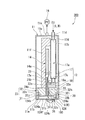
- it is a schematic configuration diagram of the ink jet recording apparatus 1 viewed from the right side, and is a diagram showing a part of the configuration in cross-section.
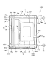
- 1 is a front view of an inkjet head 10 in Embodiment 1 of the present invention.
- Example 1 of this invention it is the schematic block diagram of the inkjet recording device 1 seen from the right side surface, Comprising: It is the figure which displayed a part of structure by the cross section.
- FIG. 5 is a cross-sectional view taken along the line II in FIG. 4 in Embodiment 1 of the present invention. 4 is an exploded perspective view of the head chip 20 in the embodiment of the present invention.
- FIG. 4 is an exploded perspective view showing details of a ceramic piezoelectric plate 21 and an ink chamber plate 22 in the embodiment of the present invention.
- FIG. 1 of this invention it is principal part sectional drawing of an inkjet head, and is an enlarged view equivalent to FIG.
- it is the figure which showed the relationship between the suction pump 16, the atmospheric
- it is a principal part enlarged sectional view of head chip 20 showing operation at the time of initial filling.
- Example 2 of this invention It is a principal part expanded sectional view of the inkjet head in Example 2 of this invention. It is a principal part expanded sectional view of the inkjet head in Example 3 of this invention. It is a front view of the inkjet head in other composition of the present invention. It is sectional drawing of the inkjet head in the other structure of this invention.
- FIG. 1 is a perspective view illustrating an ink jet recording apparatus (liquid jet recording apparatus) 1 according to a first embodiment of the present invention
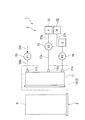
- FIG. 2 is a schematic configuration diagram of the ink jet recording apparatus 1.
- the ink jet recording apparatus 1 is connected to a predetermined personal computer, and prints on a box D by ejecting (jetting) ink (liquid) I based on print data sent from the personal computer. It is.
- the ink jet recording apparatus 1 includes a belt conveyor 2 that conveys the box body D in one direction, an ink discharge unit 3 that includes a plurality of ink jet heads (liquid ejecting heads) 10, and ink in the ink jet head 10 as shown in FIG.
- An ink supply unit 5 that supplies (first liquid) I and a cleaning liquid (second liquid) W for cleaning, and a suction pump (suction unit) 16 connected to the inkjet head 10 are provided.
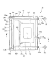
- the ink ejection unit 3 ejects ink I to the box D, and includes four rectangular parallelepiped housings 6 as shown in FIG. (See FIG. 2).
- Two housings 6 are disposed on both sides of the belt conveyor 2 in the width direction with the ink discharge surfaces 6a facing the belt conveyor 2 side.
- Two casings 6 respectively arranged on both sides in the width direction of the belt conveyor 2 are arranged side by side in the vertical direction and supported by support members 7 respectively. Note that an opening 6 b is formed in the ink ejection surface 6 a of the housing 6.
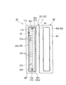
- FIG. 4 is a schematic configuration diagram of the inkjet head 10 viewed from the right side
- FIG. 5 is a cross-sectional view taken along the line II of FIG.
- the inkjet head 10 includes a case 11, a liquid supply system 12, a head chip 20, a drive circuit board 14 (see FIG. 5), a suction channel 15, and an air release channel (atmosphere). Open portion) 33.
- the case 11 has a thin box shape in which an exposure hole 11b is formed in the front surface 11a, and is fixed in the housing 6 with the thickness direction facing the horizontal direction and the exposure hole 11b facing the opening 6b. Has been. As shown in FIGS. 4 and 5, the case 11 is formed with a through hole communicating with the internal space on the back surface 11c. Specifically, the air communication hole 11h is located at the upper part in the height direction and is substantially in the middle. An ink injection hole 11d is formed at the position, and an ink suction hole 11e is formed at the lower part.
- the case 11 includes a base plate 11 f that is erected and fixed to the case 11 in the internal space, and accommodates each component of the inkjet head 10.
- the liquid supply system 12 communicates with the ink supply unit 5 through the ink injection hole 11d, and is schematically configured from a damper 17 and an ink flow path substrate 18.
- the damper 17 is for adjusting the pressure fluctuation of the ink I, and includes a storage chamber 17 a for storing the ink I.
- the damper 17 is fixed to the base plate 11f, and is connected to the ink intake hole 17b connected via the ink injection hole 11d and the pipe member 17d, and via the ink flow path substrate 18 and the pipe member 17e. And an ink outflow hole 17c.
- the ink flow path substrate 18 is a vertically formed member.
- a flow path 18a through which the ink I flows is formed so as to communicate with the damper 17 therein. And is attached to the head chip 20.
- the drive circuit board 14 includes a control circuit (not shown) and a flexible board 14a.
- the drive circuit board 14 has a ceramic piezoelectric plate (corresponding to a print pattern) by joining one end of a flexible board 14a to a plate electrode 28 described later and the other end to a control circuit (not shown) on the drive circuit board 14. A voltage is applied to the actuator 21.
- the drive circuit board 14 is fixed to the base plate 11f.
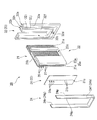
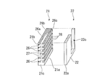
- FIG. 6 is an exploded perspective view of the head chip 20
- FIG. 7 is an exploded perspective view showing details of the ceramic piezoelectric plate 21 and the ink chamber plate 22.
- an opening / closing mechanism 60 (see FIG. 8), which will be described later, is omitted.
- the head chip 20 includes a ceramic piezoelectric plate 21, an ink chamber plate 22, a nozzle body (ejection body) 23, and a wall portion 24.
- the ceramic piezoelectric plate 21 is a substantially rectangular plate-shaped member made of PZT (lead zirconate titanate). As shown in FIGS. 6 and 7, one of the two plate surfaces 21a and 21b is formed on one plate surface 21a. A plurality of long grooves (pressure generation chambers) 26 are arranged in parallel, and each long groove 26 is isolated by a side wall 27.
- PZT lead zirconate titanate
- each long groove 26 extends in the short direction of the ceramic piezoelectric plate 21, and a plurality of the long grooves 26 are arranged in parallel over the entire length in the longitudinal direction of the ceramic piezoelectric plate 21.
- each long groove 26 has a rectangular cross section along the thickness direction of the piezoelectric actuator.
- the bottom surface of each long groove 26 has a front flat surface 26a extending from the front side surface 21c of the ceramic piezoelectric plate 21 to a substantially central portion in the short side direction, and a groove depth from the rear portion of the front flat surface 26a toward the rear side surface. Is formed of an inclined surface 26b that gradually becomes shallow and a rear flat surface 26c that extends from the rear portion of the inclined surface 26b toward the rear side surface.
- Each long groove 26 is formed by a disk-shaped die cutter.
- a plurality of side walls 27 are juxtaposed along the longitudinal direction of the ceramic piezoelectric plate 21 to divide the long grooves 26.
- a plate-like electrode 28 for applying a driving voltage is extended across the short direction of the ceramic piezoelectric plate 21 on the opening side (the plate surface 21a side) of the long groove 26 on both wall surfaces of each side wall 27.
- the plate electrode 28 is formed by vapor deposition from a known oblique direction.
- the plate-like electrode 28 is joined to the flexible substrate 14a described above.
- such a ceramic piezoelectric plate 21 has a rear surface side of the plate surface 21b fixed to the edge of the base plate 11f, and the extending direction of the long groove 26 is directed to the exposure hole 11b.
- the ink chamber plate 22 is a substantially rectangular plate-like member like the ceramic piezoelectric plate 21, and the longitudinal dimension thereof is substantially the same as the dimension of the ceramic piezoelectric plate 21.
- the dimensions in the short direction are short.
- the ink chamber plate 22 includes an open hole 22 c that penetrates in the thickness direction and is formed along the longitudinal direction of the ink chamber plate 22.
- the ink chamber plate 22 can be formed of a ceramic plate, a metal plate, or the like, but a ceramic plate having an approximate thermal expansion coefficient is used in consideration of deformation after joining with the ceramic piezoelectric plate 21.
- the ink chamber plate 22 has a ceramic piezoelectric plate from the plate surface 21 a side so that the front side surface 22 a forms a butt surface 25 a that is flush with the front side surface 21 c of the ceramic piezoelectric plate 21. It is joined to the plate 21. In this joined state, the open holes 22c expose the plurality of long grooves 26 of the ceramic piezoelectric plate 21 throughout, open all the long grooves 26 outward, and the long grooves 26 are in communication with each other. As shown in FIG. 5, the ink flow path substrate 18 is attached to the ink chamber plate 22 so as to cover the open hole 22c, and the flow path 18a of the ink flow path substrate 18 and each long groove 26 communicate with each other. .
- the nozzle body 23 is configured by attaching a nozzle plate 31 to a nozzle cap 32.
- the nozzle plate 31 is a thin plate-like and elongated member made of polyimide or the like, and a plurality of nozzle holes 31a penetrating in the thickness direction are arranged to form a nozzle row 31c. ing. More specifically, the same number of nozzle holes 31 a as the long grooves 26 are formed on the same line at the middle position in the short direction of the nozzle plate 31 and at the same intervals as the long grooves 26.
- a water repellent film having water repellency for preventing ink adhesion and the like is formed on the plate surface where the nozzle discharge port (nozzle outlet) 31 b for discharging the ink I opens.
- the other plate surface is a joint surface between the butting surface 25 a and the nozzle cap 32.
- the nozzle hole 31a is formed using an excimer laser device.
- the nozzle cap 32 is a member having a shape obtained by scraping the outer peripheral edge of one of the two frame surfaces of the frame plate-shaped member, and includes a thin plate-shaped outer frame portion 32a and an outer frame.
- the inner frame portion 32h that is thicker than the portion 32a, the inner frame portion 32b that is thicker than the middle frame portion 32h, and the middle portion of the inner frame portion 32b that penetrates in the thickness direction and extends in the longitudinal direction. It is a member provided with the long hole 32c which exists, and the discharge hole 32d penetrated in the thickness direction in the one end part of the middle frame part 32h.
- the middle frame portion 32h and the inner frame portion 32b protrude stepwise in the thickness direction from the outer frame surface 32e of the outer frame portion 32a, and the cross-sectional contour in the thickness direction faces the elongated hole 32c.
- the outer frame portion 32a, the middle frame portion 32h, and the inner frame portion 32b are stepped in order.
- a nozzle plate 31 is attached to the inner frame surface 32f extending in the same direction as the outer frame surface 32e so as to close the long hole 32c, and extends in a direction orthogonal to the outer frame surface 32e and the outer frame surface 32e.
- the wall 24 is in contact with the outer frame surface 32e.
- Such a nozzle body 23 is accommodated in the internal space of the case 11 and fixed to the case 11 and the base plate 11f so that the discharge hole 32d of the nozzle cap 32 is positioned on the lower side (see FIG. 3). 5).
- a part of the ceramic piezoelectric plate 21 and the ink chamber plate 22 is inserted into the long hole 32 c, and the butting surface 25 a is butted against the nozzle plate 31.
- the nozzle plate 31 is bonded to the inner frame surface 32f with an adhesive, and the area of the nozzle plate 31 is larger than the area of the inner frame surface 32f. It is installed slightly beyond 32f.
- the wall portion 24 is a substantially frame-shaped member made of stainless steel. As described above, the one edge 24p (hereinafter referred to as the rear end 24p) side of the wall portion 24 abuts on the outer frame surface 32e and is fixed by an adhesive or the like. Further, the other edge 24q (hereinafter, front end portion 24q) side of the wall portion 24 extends from the rear end portion 24p side in a direction substantially perpendicular to the nozzle plate 31, and the wall portion 24 surrounds the nozzle plate 31. It has become.
- the front end portion 24q side of the wall portion 24 is formed up to the same surface as the front surface 11a of the case, and forms a wall portion opening 24n substantially equal to the area of the middle frame surface 32j of the middle frame portion 32h. Yes. Therefore, the entire surface of the nozzle plate 31 is exposed from the wall opening 24n (see FIG. 3).
- a region surrounded by the wall 24 constitutes an inner space S (hereinafter referred to as a space S) of the wall 24.
- the wall 24 has a titanium coating hydrophilic film 24g (see FIG. 6) formed on the inner surface 24e, and the inner surface 24e and the outer surface 24f facing away from the inner surface 24e and the end face of the front end 24q are coated with fluororesin. Further, a water repellent film (see FIG. 6) is formed by Teflon (registered trademark) plating.
- the suction channel 15 is configured such that one end of a tube tube serving as a suction port 15a is fitted and fixed in the discharge hole 32d, and the other end is connected to the ink suction hole 11e.
- a suction pump 16 mounted outside the inkjet head 10 is connected to the ink suction hole 11e via a tube.
- the suction pump 16 sucks air and ink I in the space S to make the space S a negative pressure chamber R.
- the suction pump 16 stores the ink I sucked into the waste liquid tank E (see FIG. 2).
- the suction pump 16 may be mounted on the inkjet head 10 or may be separately provided on the apparatus side as an inkjet recording apparatus as in the present embodiment.
- the suction pump 16 since the suction pump 16 is provided on the apparatus side, it is not necessary to attach the suction pump 16 to the inkjet head 10 side, the configuration of the inkjet head 10 can be simplified, and the inkjet head 10 can be simplified. Miniaturization is possible.
- the air opening flow path 33 is provided in the upper part of the middle frame part 32h (on the opposite side of the discharge hole 32d), and one end side is fitted and fixed in the opening hole 32n penetrating in the thickness direction of the middle frame part 32h.
- the other end is connected to the atmosphere communication hole 11h of the case 11 described above.
- the atmosphere opening flow path 33 is formed above the nozzle holes 31 a arranged at the uppermost end in the nozzle row 31 c and constitutes an atmosphere opening port 33 a whose one end side is exposed to the space S of the wall portion 24.
- the space S of the wall portion 24 is configured to be able to communicate with the outside through the atmosphere opening flow path 33 and the atmosphere communication hole 11 h of the case 11.
- the ink supply unit 5 includes an ink tank (supply source) 51 in which the ink I is stored, a cleaning liquid tank 52 in which the cleaning liquid W is stored, and a switching valve 53 that can switch between the two flow paths. It has.
- the ink tank 51 is connected to the ink injection hole 11d via the supply pipe 57a, the switching valve 53 and the supply pipe 57c, and the cleaning liquid tank 52 is connected to the ink injection hole 11d via the supply pipe 57b, the switching valve 53 and the supply pipe 57c. That is, to the switching valve 53, supply pipes 57a and 57b are connected as inflow pipes, and a supply pipe 57c is connected as an outflow pipe.
- a tube 54a is connected to the atmosphere communication hole 11h of the case 11, and an atmosphere release valve 55 is connected via the tube 54a.
- the atmosphere release valve 55 is connected to a tube 54a serving as an outflow pipe and a tube 54b serving as an inflow pipe communicating with the tube 54a via the atmosphere release valve 55.
- the atmosphere release valve 55 allows the space S and the outside to communicate with each other through the tubes 54a and 54b, the atmosphere communication hole 11h, and the atmosphere release port 33a in the open state, while the outside and the space S are in the closed state. It is shut off. That is, the above-described atmosphere communication hole 11 h of the case 11, the atmosphere release passage 33 of the nozzle cap 32, and the atmosphere release valve 55 are configured to be able to switch between communication and blocking to the outside of the space S.
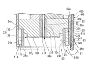
- FIG. 8 is a cross-sectional view of a main part of the ink jet head, and is an enlarged view corresponding to FIG.
- an opening / closing mechanism 60 is provided on the side of the wall opening 24 n, that is, on the side surface 11 k of the case 11.
- the opening / closing mechanism 60 is supported by a hinge portion 61 provided on the side surface 11k of the case 11, and is a door (lid member) configured to open and close the wall opening 24n of the wall portion 24 with the hinge portion 61 as a rotation center.
- a plurality of (for example, three) hinge portions 61 are arranged along the longitudinal direction of the case 11 on the side surface 11 k of the case 11, one end of which is connected to the side surface 11 k of the case 11, and the other end to the door 62. It is connected.
- the door 62 is a rectangular flat plate having an area larger than the opening area of the wall opening 24n, and is made of metal or the like.
- the door 62 has an outer surface 62a (a surface located outside in the closed state of the door 62) connected to the other end of the hinge portion 61, and is rotated about 270 degrees around the hinge portion 61 (see FIG. 8 (see the middle arrow).
- a biasing means such as a torsion spring that biases the door 62 in the closing direction is interposed between the hinge portion 61 and the door 62.
- a water-repellent film (not shown) is formed on the inner surface 62b of the door 62 (a surface located inside when the door 62 is closed) by the above-described fluororesin coating or Teflon (registered trademark) plating.
- the seal member 63 is made of an elastic material such as rubber, and is formed over the entire circumference of the outer peripheral portion of the inner surface 62b of the door 62.
- the seal member 63 is disposed so as to contact the entire circumference of the end surface of the front end portion 24q of the wall portion 24 and surround the wall portion opening 24n in the closed state of the door 62.
- a magnet 64 (see FIG. 5) capable of attracting the door 62 is disposed on the side surface 11k of the case 11.
- the magnet 64 attracts the outer surface 62 a of the door 62 to fix the door 62 in the open state when the door 62 is open, and is disposed along the longitudinal direction of the case 11.
- the door 62 opens the wall opening 24n in the open state to expose the nozzle hole 31a and the nozzle plate 31 to the outside, and closes the wall opening 24n in the closed state to close the wall 24 and the nozzle plate.
- a space S between 31 and 31 forms a closed space.
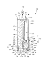
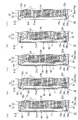
- FIG. 9 is a diagram showing the relationship between the operation timing of the suction pump 16, the air release valve 55, the opening / closing mechanism 60 (door 62) and the space S (negative pressure chamber R), and FIG. 10 shows the operation during initial filling.
- 2 is an enlarged cross-sectional view of a main part of the head chip 20 showing.
- the space S is decompressed by the air in the space S being sucked from the suction port 15a. Then, after the predetermined time T1 has elapsed, the space S becomes the negative pressure chamber R in which the negative pressure is sufficiently lower than the atmospheric pressure.
- the ink I is sucked and filled from the ink tank 51 of the ink supply unit 5.
- the ink I filled from the ink tank 51 is supplied from the ink tank 51 by connecting the supply pipe 57 a and the supply pipe 57 c with the switching valve 53.
- the ink flows through the tubes 57 a and 57 c and is injected into the ink injection hole 11 d of the inkjet head 10.
- the ink I injected into the ink injection hole 11d flows into the storage chamber 17a via the ink intake hole 17b of the damper 17, and then flows through the ink outlet hole 17c. It flows out to the flow path 18a of the road substrate 18.
- the ink I which flowed into the flow path 18a flows in into each long groove
- the ink I flowing into each long groove 26 flows to the nozzle hole 31a side and reaches the nozzle hole 31a, and then flows out from the nozzle hole 31a as excess ink Y as shown in FIG.
- the surplus ink Y starts to flow out, since the amount is small, the surplus ink Y flows downward on the nozzle plate 31.
- the ink I reaching the lower part of the negative pressure chamber R is sucked into the suction channel 15 from the suction port 15a and discharged to the waste liquid tank E (see FIG. 10B).
- the suction pump 16 is temporarily stopped (T2 in FIG. 9). Then, the air still flows from the suction port 15a toward the discharge hole 32d, so that the negative pressure chamber R is restored to return to atmospheric pressure. As a result, as shown in FIG. 10D, the surplus ink Y overflows from the nozzle hole 31a in which the filling of the ink I is completed among the nozzle holes 31a, but the filling of the ink I is not completed.
- the nozzle hole 31a is filled with the ink I up to the tip of the nozzle hole 31a. As a result, the full length groove 26 and the nozzle hole 31a are filled with the ink I. Then, after the predetermined time T3 has elapsed, the negative pressure chamber R returns to the same pressure as the atmospheric pressure again.
- the suction pump 16 is stopped after a predetermined time T5 has elapsed, and the suction filling of the ink I is completed. Then, as the suction pump 16 is stopped, the surplus ink Y does not flow out of the nozzle hole 31a, and the surplus ink Y remaining in the negative pressure chamber R is sucked. After completion of the filling of the ink I, the long groove 26 is filled with the ink I as shown in FIG. At the same time, the door 62 of the opening / closing mechanism 60 is opened and the outer surface 62a of the door 62 is attracted to the magnet 64, whereby the wall opening 24n is opened and the printable state is enabled. Thereby, the initial filling of the ink I is completed.
- the belt conveyor 2 is driven with the ink supply unit 5 set as described above (see FIG. 1), and the box D is conveyed in one direction.
- the ink ejection unit 3 ejects ink droplets toward the box body D.
- the drive circuit board 14 selectively applies a voltage to a predetermined plate electrode 28 corresponding to the print data.
- the volume of the long groove 26 corresponding to the plate electrode 28 is reduced, and the ink I filled in the long groove 26 is discharged toward the box body D from the nozzle discharge port 31b.
- the long groove 26 becomes negative pressure, so that the ink I is filled into the long groove 26 through the supply pipes 57a and 57c described above.
- the ceramic piezoelectric plate 21 of the inkjet head 10 is driven according to the image data, and ink droplets are ejected from the nozzle holes 31a to land on the box D.
- an image (character) is printed at a desired position of the box D by continuously ejecting ink droplets from the inkjet head 10 while moving the box D.
- the cleaning liquid W flows out from the nozzle hole 31a through the long groove 26 and the like, and the flowing cleaning liquid W is sucked from the suction port 15a. If the inkjet recording apparatus 1 is not used for a long period of time, the ink I filled in the long groove 26 is dried and cured. In this case, if the inside of the inkjet head 10 is filled with the cleaning liquid W as in the cleaning, the inkjet recording apparatus 1 can be stored for a long period of time.
- the opening / closing mechanism 60 that forms the space S (closed space) between the wall portion 24 and the nozzle plate 31, and the atmosphere open flow path 33 that communicates the space S with the outside. It was set as the structure equipped with. According to this configuration, the wall opening 24n of the wall 24 is closed by the opening / closing mechanism 60, so that the suction pump 16 can only suck the ink I through the suction channel 15 and fill the ink I from the nozzle hole 31a. The excess ink Y that flows out can be collected.
- the air release channel 33 upward and the suction port 15a downward, air flows from the upper side to the lower side (suction port 15a) in the space S, so that the excess ink Y in the space S is removed. Suction can be reliably performed. Since the surplus ink Y that has flowed out of the nozzle hole 31a hangs downward from the nozzle hole 31a in the direction of gravity, surplus in the space S by providing the air release channel 33 (atmosphere release port 33a) above the nozzle row 31c. Even if the atmosphere opening port 24k is opened when the ink Y has stayed, the space S can be communicated with the outside while preventing the excess ink Y from flowing out from the atmosphere opening channel 33.
- the opening / closing mechanism 60 of the present embodiment is configured to rotate the door 62 via the hinge portion 61.
- the door 62 can be smoothly opened and closed by rotating the door 62 via the hinge portion 61. Then, by reducing the pressure of the space S in a state where the wall opening 24n is closed, the space S can be surely set to the negative pressure chamber R, and the recovery ability of the excess ink Y can be improved. . Further, by biasing the door 62 in the closing direction, the door 62 can be smoothly closed, and the door 62 is biased toward the wall portion 24 when the door 62 is closed. The Therefore, the adhesion between the wall portion 24 and the door 62 can be ensured.
- the seal member 63 on the inner surface 62b of the door 62, it is possible to improve the adhesion between the door 62 and the end surface of the front end portion 24q of the wall portion 24. Therefore, it is possible to reliably prevent the surplus ink Y from flowing out from the wall opening 24n. Thus, air leakage from the wall opening 24n can be prevented and the space S can be surely set to the negative pressure chamber R. Therefore, when suction is performed with the wall opening 24n open. Compared with this, it is possible to improve the recovery capability of the surplus ink Y, and it is possible to quickly perform the initial filling.
- the water repellent film tends to repel and stay in the space S.
- the recovery capability of the surplus ink Y is improved, and the surplus ink Y can be prevented from flowing out of the wall opening 24n. Further, since the surplus ink Y can be prevented from remaining on the door 62, the vicinity of the inkjet head 10 can be prevented from being contaminated by the surplus ink Y remaining on the door 62 in the open state of the door 62.
- the ink supply unit 5 is configured to be able to switch and supply the ink I and the cleaning liquid W, and the ink I and the cleaning liquid W are supplied to the liquid supply system 12, so that the labor for cleaning the inkjet head 10 is reduced. In addition, the inkjet head 10 can be efficiently cleaned.
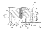
- FIG. 11 is a schematic configuration diagram of the ink jet head viewed from the right side surface according to the second embodiment of the present invention
- FIG. 12 is an enlarged cross-sectional view of a main part of the ink jet head.
- This embodiment is different from Example 1 described above in that the opening / closing mechanism is configured to be slidable. As shown in FIGS.
- the opening / closing mechanism 110 of the inkjet head 100 includes a pair of guide portions 101, a shutter 105 supported between the guide portions 101, and a front end portion 24 q of the wall portion 24. It is comprised with the sealing member 163 arrange
- the guide portion 101 is provided from the upper portion of the case 11 to the lower surface of the case 11 using a portion where the portion where the exposure hole 11b of the case 11 is formed protrudes inward.
- a shutter 105 is accommodated in the inner space of the guide portion 101, that is, between the wall portion 24 and the case 11.
- the shutter 105 is made of a thin plate having flexibility, and includes a shutter main body 105a that covers the wall opening 24n, and an engagement portion 105b that is bent on both sides in the width direction of the shutter main body 105a and engaged with the guide portion 101. It consists of and.
- the shutter 105 is configured such that the engaging portion 105b is guided by the guide portion 101 and is slidable in the vertical direction (from the lower end to the upper end of the wall opening 24n) from the lower surface of the case 11 to the upper portion of the wall portion 24. Has been. That is, in a state where the shutter 105 is disposed below the case 11 in the inner space of the guide portion 101, the shutter 105 is in an open state, the wall portion opening 24n communicates, and the nozzle hole 31a is exposed to the outside. Yes.
- the shutter 105 is disposed so as to cover from the front end portion 24q side of the wall portion 24, the shutter 105 is closed, the wall portion opening port 24n is closed, and the wall portion 24 and the nozzle plate 31 are closed.
- the space S therebetween is configured to form a closed space.
- a grip portion 106 is provided on one end side of the front surface of the shutter 105, and the above-described shutter 105 is slid by operating the grip portion 106. Further, a water repellent film (not shown) by the above-mentioned fluororesin coating or Teflon (registered trademark) plating is formed on the surface of the shutter 105 facing the nozzle plate 31 in the closed state.
- the wall opening 24n can be opened and closed by sliding the shutter 105, and therefore the door 62 (see FIG. 8) is rotated as in the first embodiment.
- the movable range of the opening / closing mechanism 110 in the normal direction of the surface of the nozzle cap 32 is smaller than the configuration in which the wall opening 24n is opened and closed. That is, since the installation space of the opening / closing mechanism 110 can be reduced, the space factor can be further improved and the degree of freedom in designing the liquid jet recording apparatus can be improved.
- the space S between the wall portion 24 and the nozzle plate 31 is communicated with the outside and opened to the atmosphere by opening only the upper end portion of the wall portion opening port 24n completely closed.
- the atmosphere opening part can be realized by the opening / closing mechanism, and it is not necessary to provide the atmosphere opening part separately. Therefore, the space S can be formed without providing the atmosphere communication hole 11h, the atmosphere release flow path 33, the atmosphere release valve 55 as in the first and second embodiments, and without causing the excess ink Y staying in the space S to leak out. It can be opened to the atmosphere.
- the inkjet head 100 can be made a simpler structure, and manufacturing cost can be reduced.
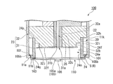
- FIG. 13 is an enlarged cross-sectional view of the main part of the inkjet head. This embodiment is different from the first and second embodiments described above in that a wiper member is provided in the opening / closing mechanism.
- the opening / closing mechanism 210 of the inkjet head 200 includes a shutter 201 supported by a guide unit (not shown) and the above-described seal member 163.
- the shutter 201 is a thin plate formed larger than the opening area of the wall opening 24n, and is guided by guides (not shown) provided in the upper and lower portions of the case 11 so that the width direction of the wall 24 (FIG. 13). It is configured to be slidable along the middle arrow direction. That is, when the shutter 201 is in the open state, the wall opening 24n is opened and the nozzle hole 31a is exposed to the outside.
- the shutter 201 when the shutter 201 is in the closed state, the shutter 201 is disposed so as to cover the wall opening 24n, closes the wall opening 24n, and spaces S between the wall 24 and the nozzle plate 31. It is comprised so that a closed space may be formed.
- a grip 202 is provided in front of the shutter 201, and the shutter 201 described above is slid by operating the grip 202. Further, a water-repellent film (not shown) is formed on the rear surface of the shutter 201 by the above-described fluororesin coating or Teflon (registered trademark) plating.
- a wiper 203 is provided along the longitudinal direction of the shutter 201 on one end side in the width direction on the back surface of the shutter 201.
- the wiper 203 is made of an elastic material such as rubber, and is provided so as to face the inside of the wall opening 24n.
- the wiper 203 extends to a position where the tip portion contacts the surface of the nozzle plate 31.
- the length of the wiper 203 is preferably longer than the nozzle row 31 c formed on the nozzle plate 31.
- the tip portion of the wiper 203 is configured to slidably contact the periphery of the nozzle hole 31 a on the surface of the nozzle plate 31.
- the wiper 203 is brought into sliding contact with the surface of the nozzle plate 31 following the opening / closing operation of the shutter 201, and therefore, the surplus ink Y adhered to the surface of the nozzle plate 31 simultaneously with the opening / closing of the shutter 201.
- the space factor can be improved by effectively using the inner space of the wall portion 24.
- the wiper effect can be achieved simultaneously with the opening / closing operation of the shutter 201, a separate wiper process is not required after the ink I is filled, and the working efficiency can be improved.
- the nozzle body 23 includes the nozzle plate 31 and the nozzle cap 32, and the rear end 24p of the wall portion 24 is attached to the nozzle cap 32, but the suction port 15a is a space. You may make it adhere to the nozzle plate 31 on condition that it is opened by S.
- the suction port 15a is fitted into the discharge hole 32d formed in the nozzle cap 32.
- the discharge hole 32d may be formed in the nozzle plate 31 or the wall portion 24.
- the suction flow path 15 may be connected to the discharge hole 32d, and the discharge hole 32d may be used as a suction port.
- the water repellent film 24h is formed by fluororesin coating or Teflon (registered trademark) plating. However, a water repellent sheet may be attached or a water repellent may be applied.
- the hydrophilic film 24g is formed by titanium coating. However, gold plating may be applied, or an alkaline chemical may be applied.
- the inkjet recording apparatus 1 is configured by fixing the inkjet head 10.
- the inkjet recording apparatus 1 may be configured by moving the inkjet head 10. That is, if the ink-jet head 10 is employed, an ink-jet recording apparatus that does not require a cap for suctioning with negative pressure can be realized.
- the arrangement direction of the nozzle row 31c of the ink jet head 10 is directed to the direction of gravity, and the opening direction of the nozzle hole 31a is directed to the horizontal direction. It is not limited to the direction.
- the opening direction of the nozzle holes 31a may be directed in the direction of gravity, or the extending direction of the nozzle rows 31c may be directed in the horizontal direction.
- the suction pump is operated at the time of initial filling and cleaning.
- the ink I may drip from the nozzle hole 31a even during printing, and even if such ink I is collected. Good.
- the opening / closing mechanism is provided on the wall portion 24 .
- the wall portion opening 24n of the wall portion 24 is closed by a lid member or the like separate from the wall portion 24. It is good also as a simple structure.
- the air release channel 33 is not necessarily provided on the wall 24 side, and a configuration in which an air release port is provided in the opening / closing mechanism is also possible. Further, the opening / closing operation of the lid member may be automatic or manual.
- the wall portion 24 is used to form the space S and the negative pressure chamber R.
- the wall portion 24 may be a member called a nozzle guard that defends the nozzle plate. The details of the nozzle guard are described below.
- FIG. 14 is a front view of an inkjet head according to another configuration of the present invention
- FIG. 15 is a cross-sectional view.
- symbol is attached
- the nozzle guard 124 of the ink jet head 300 is a substantially box-shaped member made of stainless steel, and is formed by press molding.
- the nozzle guard 124 includes a top plate portion 124a formed in a rectangular plate shape, and a sealed portion 124b extending from the peripheral edge portion of the top plate portion 124a in a direction substantially orthogonal to the plate surface direction.
- the top plate portion 124a has a plate surface that is substantially the same size as the middle frame surface 32j, and includes a slit (opening portion) 124c that extends in the longitudinal direction at an intermediate portion in the short direction of the top plate portion 124a. .
- the slit 124c is formed to be slightly longer than the length of the nozzle row 31c, and both end portions (upper end portion 124i, lower end portion 124j) are formed in a circular shape.
- the width dimension of the slit 124c is set to about 1.5 mm with respect to the nozzle diameter of 40 ⁇ m of the nozzle hole 31a.
- the width dimension of the slit 124c is the upper limit of the width dimension that can be made negative pressure by the suction pump 16, and the lower limit is the width dimension at which the ink I does not overflow from the slit 124c during the initial filling of the ink I. It is desirable to set the range.
- the upper end part 124i and the lower end part 124j are formed in a circle with a diameter slightly larger than the width dimension described above.
- This nozzle guard 124 has a hydrophilic film (not shown) formed by titanium coating on an inner surface 124e facing inward, a fluorine resin on the inner surface 124e and an outer surface 124f facing away from the inner surface 124e.
- a water repellent film (not shown) is formed by coating or Teflon (registered trademark) plating.
- the top plate portion 124a covers the inner frame portion 32b and the discharge hole 32d (see FIG. 14), and the inner surface 124e of the sealing portion 124b and the inner side surface 32i of the middle frame portion 32h.
- the rear end 24p is adhered to the outer frame surface 32e with an adhesive so as to be in contact with the nozzle cap 32 (see FIG. 15).
- the nozzle row 31c is covered via the space (inner space) S so that the slit 124c faces the nozzle row 31c and does not face the discharge hole 32d.
- the nozzle discharge port 31b is covered so as to face the nozzle row 31c from the slit 124c and not to face the discharge hole 32d (see FIG. 14).
- the nozzle guard 124 has an upper limit for the distance between the top plate portion 124a and the nozzle plate 31 that can be set to a negative pressure by the suction pump 16, and the ink I overflows from the slit 124c during the initial filling of the ink I. It is desirable to set in a range with the lower distance as the lower limit.
- an opening / closing mechanism 160 is provided on the outer surface 124f of the top plate portion 124a.
- the opening / closing mechanism 160 is supported by a hinge portion 161 provided on the outer surface 124f of the top plate portion 124a.
- the door (lid) is configured to be able to open and close the slit 124c of the top plate portion 124a with the hinge portion 161 as a rotation center.
- Member) 162 urging means (not shown) for urging the door 162 in the closing direction (direction for closing the slit 124c), and a seal between the door 162 and the top plate portion 124a in the state where the slit 124c is closed.
- a sealing member 163 to be used.
- a plurality of (for example, three) hinges 161 are arranged on the side of the slit 124c along the longitudinal direction of the slit 124c, one end of which is connected to the outer surface 124f of the top plate 124a, and the other end. It is connected to the door 162.
- the door 162 is a rectangular flat plate having an area larger than the opening area of the slit 124c, and is made of metal or the like.
- the door 162 is connected to the outer surface thereof (the surface located outside in the closed state of the door 162) with the other end of the hinge portion 161, and is rotated 180 degrees around the hinge portion 161 (in FIG. 15). (See arrow).
- a biasing means such as a torsion spring that biases the door 162 in the closing direction is interposed between the hinge portion 161 and the door 162.
- a water-repellent film (not shown) is formed on the inner surface 162a of the door 162 (the surface located inside when the door 162 is closed) by the above-described fluororesin coating or Teflon (registered trademark) plating.
- the seal member 163 is made of an elastic material such as rubber and is disposed so as to surround the entire circumference of the slit 124c on the outer surface 124f of the top plate portion 124a.
- the seal member 163 is configured to be able to come into contact with the other surface of the door 162 when the door 162 is closed.
- a magnet (not shown) that can attract the door 162 is disposed on the opposite side of the seal member 163 across the hinge portion 161 in the surface direction of the top plate portion 124a. When the door 162 is in the open state, the magnet attracts the outer surface of the door 162 and fixes the door 162 in the open state, and is disposed along the longitudinal direction of the slit 124c.
- the door 162 opens the slit 124c in the open state to expose the nozzle hole 31a to the outside, and closes the slit 124c in the closed state to close the space S between the nozzle guard 124 and the nozzle plate 31. Is formed.
- the communication between the space S and the outside can be switched between opening and closing by opening / closing only the slit 124c by the opening / closing mechanism 160.
- the movable range of the door 162 in the normal direction of the surface of the top plate portion 124a is small as compared with the configuration in which the wall opening port 24n is opened and closed.
- the opening / closing mechanism 60 of Example 1 mentioned above showed the form which the hinge part 61 protruded in the direction substantially orthogonal to the nozzle plate 31 from the front surface 11a and the front-end part 24q of the case 11, the structure which the hinge part 61 protruded You don't have to. That is, it is good also as a state in which the structure is not formed in the direction of the box D from the front surface 11a and the front-end part 24q of the case 11.
- FIG. Although not shown, in this case, a hinge portion 61 is formed on the side surface 11k of the case 11, and the hinge portion 61 does not protrude from the case 11 to the box D side.
- the shape of the door 62 can be changed according to the necessity of the opening / closing operation. Further, also in the second embodiment, it is possible to realize a configuration in which the shutter 105 does not protrude from the front surface 11a of the case 11 to the box body D side by providing the guide portion 101 with which the engaging portion 105b is engaged in the front end portion 24q. is there. Also in the third embodiment, a configuration in which a guide portion (not shown) is provided in the wall portion 24 and the shutter 201 does not protrude from the front surface 11a of the case 11 to the box body D side can be realized. By configuring in this way, the distance from the front surface 11a of the case 11 to the box D can be shortened, so that the printing accuracy can be improved.
- the excess ink Y sucked by the suction pump 16 is discharged to the waste liquid tank E.
- the configuration connected to the flow path on the outlet side of the suction pump 16 may be the ink tank 51 instead of the waste liquid tank.
- the excess ink Y sucked by the suction pump 16 may be supplied to the ink tank 51 and supplied from the ink tank 51 to the inkjet head 10 as the ink I.
- the surplus ink Y can be reused as the ink I.
- a filter member may be provided in a flow path from the suction pump 16 to the ink tank 51 when the excess ink Y is reused.
- a deaeration device may be provided in the flow path from the suction pump 16 to the ink tank 51.
- Atmospheric open flow path (atmospheric open section) 26 ... Long groove (pressure generating chamber) 31a ... Nozzle hole 31b ... Nozzle outlet (jet outlet) 31c ... Nozzle array (injection) (Hole row) 32k ... groove 60, 110, 210 ... opening / closing mechanism 61 ... hinge part 62 ... door (lid member) 6 ... sealing member 105,201 ... shutter (cover member) I ... ink (first liquid) R ... negative pressure chamber S ... space (inside space) W ... cleaning liquid (second liquid)
Abstract
Description
(1)液体噴射ヘッドのスペースファクタを向上させ、液体噴射記録装置の設計の自由度を向上させる。
(2)簡素な構成で余剰液体の回収能力を向上させて、余剰液体による汚染を防止すると共に液体噴射記録装置の初期充填を実現し、液体充填後の液体噴射を安定させる。
液体噴射ヘッドに係る解決手段として、複数の噴射孔からなる噴射孔列を有する噴射体と、前記各噴射孔と対となって前記噴射孔に連通する複数の圧力発生室と、前記圧力発生室及び前記噴射孔に第一液体を供給する液体供給系と、前記圧力発生室に隣接配置されたアクチュエータとを備え、前記アクチュエータを駆動して前記圧力発生室を加圧し、前記第一液体を前記噴射孔の液体噴射口から噴射させる液体噴射ヘッドにおいて、前記噴射体の周囲を囲むように設けられ、前記噴射孔に対向する開口部を有する壁部と、開状態において前記開口部を開口して前記噴射孔を外部に露出させる一方、閉状態において前記開口部を閉塞して前記壁部と前記噴射体との間に閉空間を構成する開閉機構と、一端側が前記噴射孔列の下方において吸引口として開口するとともに、他端側が吸引部に接続され、前記吸引部により前記閉空間内を吸引させることで、前記閉空間を負圧室にさせ、前記第一液体の供給源から前記第一液体を前記圧力発生室及び前記噴射孔に供給させる吸引流路と、前記閉空間の外部への連通及び遮断を切り換え可能な大気開放部とを備えている、という手段を採用する。
すなわち、開口部を閉塞して壁部と噴射体との間を閉空間とした状態で閉空間の空気を吸引部により吸引させると、閉空間が減圧されて負圧室となる。これにより、第一液体の供給源から噴射体に第一液体が流入するため、第一液体を吸引充填することができる。さらに、開口部を閉塞しておくことで、第一液体の充填時に噴射体から流出する余剰液体が開口部から流出することを防ぐことができる。そして、第一液体を充填した後に大気開放部を開放した状態で、吸引流路を介して吸引部により閉空間内の空気を吸引させると、大気開放部を介して外部から閉空間に向けて空気が流通するため、供給源の第一液体は吸引されず、閉空間内の圧力が復圧する。その後、外部から閉空間に流入した空気は吸引流路を介して外部に排出される。この時、噴射体から流出して閉空間内に滞留した余剰液体が閉空間内を流通する空気とともに、外部に排出される。
したがって、従来のように複雑なサービスステーションを設けることがなく、簡素な構成で余剰液体による汚染を防止すると共に液体噴射記録装置の初期充填を実現することができる。そのため、液体充填後の液体噴射を安定させることもできる。また、壁部の内側空間(閉空間)において、余剰液体の回収を行うことができるため、余剰液体の回収能力を向上させた上で、余剰液体を回収するスペースを極めて小さいものとし、液体噴射ヘッドのスペースファクタを向上させることができる。これにより、液体噴射ヘッドの設計の自由度を向上させることができる。
この構成によれば、大気開放部を上方に、吸引口を下方に設けることで、閉空間内の上方から下方(吸引口)に向かって空気が流通するため、閉空間内の余剰液体を確実に吸引することができる。また、噴射体から流出した余剰液体は噴射体から重力方向下方に垂下していくため、大気開放部を上方に設けることで閉空間内に余剰液体が滞留したとしている場合に大気開放部を開放しても、大気開放部から余剰液体が流出することを防いだ上で、閉空間と外部とを連通させることができる。
この構成によれば、ヒンジ部を介して蓋部材を回動させることで、蓋部材の開閉動作をスムーズに行うことができる。この状態で、壁部またはケースと噴射体との間の閉空間を減圧することで、閉空間を確実に負圧室とすることが可能になり、余剰液体の回収能力を向上させることができる。
この構成によれば、蓋部材を閉方向に付勢しておくことで、蓋部材の閉動作をスムーズに行うことができるとともに、蓋部材が閉状態の場合に壁部に向けて蓋部材が付勢される。そのため、壁部と蓋部材との密着性を確保することができ、余剰液体が開口部から流出することを確実に防ぐことができる。これにより、開口部からの空気リークを防止して、閉空間を確実に負圧室とすることが可能になるため、開口部を開口した状態で吸引を行う場合に比べて、余剰液体の回収能力を向上させることができるとともに、初期充填を迅速に行うことができる。
この構成によれば、蓋部材をスライドさせることにより開口部の開閉を行うことができるため、蓋部材を回動させて開口部の開閉を行う構成に比べて噴射体の表面の法線方向における開閉機構の可動範囲が小さい。すなわち、開閉機構の設置スペースを縮小することができるため、よりスペースファクタを向上させ、液体噴射記録装置の設計の自由度を向上させることができる。
この構成によれば、蓋部材のスライド動作(開閉動作)に追従してワイパー部材が噴射体の表面に摺接するため、蓋部材の開閉と同時に噴射体の表面に付着した余剰液体や噴射体孔の噴射口から表面張力により突出した余剰液体を回収することができる。これにより、壁部の内側空間を有効利用して、スペースファクタを向上させることができる。また、蓋部材の開閉動作と同時にワイパー効果を奏することができるため、第一液体の充填後にワイパー工程を別途設けることがなく、作業効率を向上させることができる。
この構成によれば、蓋部材をスライド途中で係止して、開口部の上端部分のみを開放した状態で保持させるような構成も可能である。この場合、開口部を完全に閉塞した状態から、開口部の上端部分のみを開放させることで、壁部と噴射体との間の閉空間が外部と連通して大気開放されることになる。すなわち、開閉機構によって大気開放部を実現することが可能になり、別途大気開放部を設ける必要がない。そのため、大気開放するためのバルブ等を設けることなく、かつ閉空間に滞留した余剰液体を漏出させることなく、閉空間を大気開放させることができる。これにより、液体噴射ヘッドをより簡素な構成にすることができ、製造コストを低減することができる。
この構成によれば、蓋部材と壁部との間の密着性を向上させることができるため、余剰液体が開口部から流出することを確実に防ぐことができる。これにより、開口部からの空気リークを防止して、閉空間を確実に負圧室とすることが可能になるため、開口部を開口した状態で吸引を行う場合に比べて、余剰液体の回収能力を向上させることができるとともに、初期充填を迅速に行うことができる。
この構成によれば、余剰液体が開口部から外部に漏出しようとしても、撥水膜にはじかれて閉空間に留まり易くなるので、余剰液体の回収能力が向上すると共に余剰液体が開口部から流出することを防ぐことができる。また、蓋部材に余剰液体が残存することを防ぐことができるため、蓋部材の開状態において蓋部材に残存した余剰液体により液体噴射ヘッド近傍が汚染されることを防ぐことができる。
この構成によれば、噴射孔列と対向する開口部を天板部に形成することで、開口部の面積を縮小することができ、開閉機構の可動範囲を小さくすることができる。したがって、開閉機構の設置スペースを縮小することができる。
この構成によれば、上記解決手段を採用したいずれかの液滴噴射ヘッドを備えているため、吸引流路を介して吸引部により吸引させるのみで、液体供給部に貯留された第一液体の充填及び噴射体から流出する余剰液体の回収を行うことができる。
したがって、従来のように複雑なサービスステーションを設けることがなく、簡素な構成で余剰液体による汚染を防止すると共に液体噴射記録装置の初期充填を実現することができる。そのため、液体充填後の液体噴射を安定させることもできる。
この構成によれば、液体供給系に二種類の液体が供給されるので、例えば、液体供給系にインクと洗浄液とを切り換え供給して、液体噴射ヘッドの清掃に対する労力を低減させると共に、効率よく清掃をすることができる。
この構成によれば、液体噴射ヘッド側に吸引部を取り付ける必要がないので、液体噴射ヘッドの構成の簡素化が可能になるとともに、液体噴射ヘッドの小型化が可能になる。
この発明によれば、負圧室内に溢れ出た第一液体を再利用することができる。
この発明によれば、適切な状態の液体を再利用することができる。
この構成によれば、壁部の開口部を開閉機構により閉塞することで、噴射孔列の下方に設けられた吸引流路を介して吸引部により吸引させるのみで、第一液体の充填及び噴射体から流出する余剰液体の回収を行うことができる。
すなわち、開口部を閉塞して壁部と噴射体との間を閉空間とした状態で閉空間の空気を吸引部により吸引すると、閉空間が減圧されて負圧室となる。これにより、第一液体の供給源から噴射体に第一液体が流入するため、第一液体を吸引充填することができる。さらに、開口部を閉塞しておくことで、第一液体の充填時に噴射体から流出する余剰液体が開口部から流出することを防ぐことができる。そして、第一液体を充填した後に大気開放部を開放した状態で、吸引流路を介して吸引部により閉空間内の空気を吸引すると、大気開放部を介して外部から閉空間に向けて空気が流通するため、供給源の第一液体は吸引されず、閉空間内の圧力が復圧する。その後、外部から閉空間に流入した空気は吸引流路を介して外部に排出される。この時、噴射体から流出して閉空間内に滞留した余剰液体が閉空間内を流通する空気とともに、外部に排出される。
したがって、従来のように複雑なサービスステーションを設けることがなく、簡素な構成で余剰液体による汚染を防止すると共に液体噴射記録装置の初期充填を実現することができる。そのため、液体充填後の液体噴射を安定させることもできる。また、壁部の内側空間(閉空間)において、余剰液体の回収を行うことができるため、余剰液体の回収能力を向上させた上で、余剰液体を回収するスペースを極めて小さいものとし、液体噴射ヘッドのスペースファクタを向上させることができる。これにより、液体噴射ヘッドの設計の自由度を向上させることができる。
すなわち、開口部を閉塞して壁部と噴射体との間を閉空間とした状態で閉空間の空気を吸引部により吸引させると、閉空間が減圧されて負圧室となる。これにより、第一液体の供給源から噴射体に第一液体が流入するため、第一液体を吸引充填することができる。さらに、開口部を閉塞しておくことで、第一液体の充填時に噴射体から流出する余剰液体が開口部から流出することを防ぐことができる。そして、第一液体を充填した後に大気開放部を開放した状態で、吸引流路を介して吸引部により閉空間内の空気を吸引させると、大気開放部を介して外部から閉空間に向けて空気が流通するため、供給源の第一液体は吸引されず、閉空間内の圧力が復圧する。その後、外部から閉空間に流入した空気は吸引流路を介して外部に排出される。この時、噴射体から流出して閉空間内に滞留した余剰液体が閉空間内を流通する空気とともに、外部に排出される。
したがって、従来のように複雑なサービスステーションを設けることがなく、簡素な構成で余剰液体による汚染を防止すると共に液体噴射記録装置の初期充填を実現することができる。そのため、液体充填後の液体噴射を安定させることもできる。また、壁部の内側空間(閉空間)において、余剰液体の回収を行うことができるため、余剰液体の回収能力を向上させた上で、余剰液体を回収するスペースを極めて小さいものとし、液体噴射ヘッドのスペースファクタを向上させることができる。これにより、液体噴射ヘッドの設計の自由度を向上させることができる。
図1は、本発明の実施例1に係るインクジェット記録装置(液体噴射記録装置)1を示す斜視図であり、図2は、インクジェット記録装置1の概略構成図である。このインクジェット記録装置1は、所定のパーソナルコンピュータに接続されており、このパーソナルコンピュータから送られた印刷データに基づいて、インク(液体)Iを吐出(噴射)して箱体Dに印刷を施すものである。インクジェット記録装置1は、箱体Dを一方向に搬送するベルトコンベア2と、複数のインクジェットヘッド(液体噴射ヘッド)10を備えるインク吐出部3と、図2に示すように、インクジェットヘッド10にインク(第一液体)I及びクリーニング用洗浄液(第二液体)Wを供給するインク供給部5と、インクジェットヘッド10に接続された吸引ポンプ(吸引部)16とを備えている。
図3は、インクジェットヘッド10の正面図であり、図4は、右側面から見たインクジェットヘッド10の概略構成図であり、図5は、図4のI-I線断面図である。
インクジェットヘッド10は、図4に示すように、ケース11と、液体供給系12と、ヘッドチップ20と、駆動回路基板14と(図5参照)、吸引流路15と、大気開放流路(大気開放部)33とを備えている。
ダンパー17は、図5に示すように、インクIの圧力変動を調整するためのものであり、インクIを貯留する貯留室17aを備えている。このダンパー17は、ベースプレート11fに固定されており、インク注入孔11dと管部材17dとを介して接続されるインク取込孔17bと、インク流路基板18と管部材17eを介して接続されるインク流出孔17cとを備えている。
インク流路基板18は、図4に示すように、縦長に形成された部材であって、図5に示すように、その内部にダンパー17と連通してインクIが流通する流通路18aが形成された部材であり、ヘッドチップ20に取り付けられている。
図6は、ヘッドチップ20の分解斜視図であり、図7はセラミック圧電プレート21及びインク室プレート22の詳細を示す分解斜視図である。なお、図6においては、後述する開閉機構60(図8参照)を省略する。
ヘッドチップ20は、図6に示すように、セラミック圧電プレート21と、インク室プレート22と、ノズル体(噴射体)23と、壁部24とを備えている。
なお、このインク室プレート22は、セラミックプレート、金属プレートなどで形成することができるが、セラミック圧電プレート21との接合後の変形を考えて、熱膨張率の近似したセラミックプレートを用いている。
インク室プレート22には、図5に示すように、開放孔22cを覆うようにしてインク流路基板18が装着され、インク流路基板18の流通路18aと各長溝26とが連通している。
ノズルプレート31は、図6に示すように、ポリイミド等からなる薄板状、かつ、細長状の部材であり、厚さ方向に貫通する複数のノズル孔31aが列設してノズル列31cを構成している。より具体的には、長溝26と同数のノズル孔31aが、ノズルプレート31の短手方向中間の位置において同一線上に、かつ、長溝26と同一の間隔で形成されている。
ノズルプレート31の二つの板面のうち、インクIを吐出するノズル吐出口(ノズル噴出口)31bが開口する板面には、インクの付着等を防止するための撥水性を有する撥水膜が塗布されており、他方の板面は上記突合わせ面25a及びノズルキャップ32との接合面とされている。
なお、ノズル孔31aは、エキシマレーザ装置を用いて形成されている。
外枠面32eと同方向に延在する内枠面32fには、長孔32cを塞ぐようにノズルプレート31が貼付されており、外枠面32e及び外枠面32eの直交方向に延在する外枠面32eには、壁部24が当接している。
この状態においては、長孔32cにセラミック圧電プレート21及びインク室プレート22の一部が挿入されて、ノズルプレート31に突合わせ面25aが突き合わされている。またノズルプレート31は、内枠面32fに接着剤によって接着されているとともに、内枠面32fの面積と比較すると、ノズルプレート31の面積が大きくに形成されており、ノズルプレート31が内枠面32fから多少はみ出て設置されている。
壁部24は、ステンレス鋼からなる略枠型形状の部材である。上述の通り、壁部24の一方縁24p(以下、後端部24pという)側は、外枠面32eに当接し接着剤等によって固定されている。また壁部24の他方縁24q(以下、前端部24q)側は、ノズルプレート31と略直行する方向に後端部24p側から延出しており、壁部24がノズルプレート31を取り囲むような形状となっている。さらに壁部24の前端部24q側は、ケースの正面11aと同一面まで形成されているとともに、中枠部32hが有する中枠面32jの面積と略同等の壁部開放口24nを形成している。したがって、壁部開放口24nからは、上述したノズルプレート31の全面が露出している(図3参照)。そして、壁部24に囲まれた領域が壁部24の内側空間S(以下、空間Sという)を構成している。
なお、壁部24は、その内表面24eにチタンコーティングによる親水膜24g(図6参照)が形成されており、この内表面24eと背向する外表面24f及び前端部24qの端面にフッ素樹脂コーティングやテフロン(登録商標)メッキによる撥水膜(図6参照)が形成されている。
また、インク吸引孔11eには、インクジェットヘッド10の外部に搭載された吸引ポンプ16が、チューブを介して接続されている。この吸引ポンプ16は、作動時に、空間S内の空気及びインクIを吸引して、空間Sを負圧室Rとする。なお、この吸引ポンプ16は、廃液タンクE(図2参照)に吸引したインクIを貯留する。またこの吸引ポンプ16は、インクジェットヘッド10に搭載されていても構わないし、本実施形態のように別途インクジェット記録装置として装置側に具備されていても構わない。本実施形態では、装置側に吸引ポンプ16が設けられているため、インクジェットヘッド10側に吸引ポンプ16を取り付ける必要がなく、インクジェットヘッド10の構成の簡素化が可能になるとともに、インクジェットヘッド10の小型化が可能になる。
インクタンク51は、供給管57a、切替バルブ53及び供給管57cを介して、洗浄液タンク52は、供給管57b、切替バルブ53及び供給管57cを介してそれぞれインク注入孔11dに接続されている。すなわち、切替バルブ53には、流入管として供給管57a,57bが、流出管として供給管57cが接続されている。
図8は、インクジェットヘッドの要部断面図であり、図5に相当する拡大図である。
ここで、図8に示すように、壁部開放口24nの側方、すなわちケース11の側面11kには開閉機構60が設けられている。この開閉機構60は、ケース11の側面11kに設けられたヒンジ部61に支持され、ヒンジ部61を回動中心として壁部24の壁部開放口24nを開閉可能に構成されたドア(蓋部材)62と、ドア62を閉方向(壁部開放口24nを閉塞する方向)に付勢する付勢手段(不図示)と、壁部開放口24nを閉塞した状態のドア62と壁部24の前端部24q側の端面との間のシールするシール部材63とを備えている。
ヒンジ部61は、ケース11の側面11kに、ケース11の長手方向に沿って複数(例えば、3個)配列されており、その一端がケース11の側面11kに連結され、他端がドア62に連結されている。
図9は、吸引ポンプ16及び大気開放バルブ55、開閉機構60(ドア62)の動作タイミング及び空間S(負圧室R)との関係を示した図であり、図10は初期充填時の動作を示したヘッドチップ20の要部拡大断面図である。
まず、図4及び図9に示すように、吸引ポンプ16を作動させ、この吸引ポンプ16が吸引流路15を介して吸引口15aから空間Sの空気を吸引する(図9における時間T0)。この際、大気開放バルブ55及び開閉機構60のドア62は閉じて閉空間と外部とを遮断しておく。すると、空間Sの空気が吸引口15aから吸引されることで空間Sが減圧される。そして、所定時間T1経過後に、空間Sが大気圧よりも十分に負圧となった負圧室Rとなる。
インク注入孔11dに注入されたインクIは、図4及び図5に示すように、ダンパー17のインク取込孔17bを介して貯留室17aに流入した後に、インク流出孔17cを介してインク流路基板18の流通路18aに流出する。そして、流通路18aに流入したインクIが開放孔22cを介して各長溝26内に流入する。
これにより、全長溝26及びノズル孔31a内にインクIが充填される。そして、所定時間T3経過後に、負圧室Rは復圧して再び大気圧と同圧になる。
これと同時に、開閉機構60のドア62を開状態とし、ドア62の外表面62aをマグネット64に吸着させることで壁部開放口24nが開放され、印刷可能状態となる。これにより、インクIの初期充填が完了する。
続いて、箱体Dに印刷を施す場合の動作について説明する。最初にインク供給部5の設定について説明する。すなわち、図2に示すように、切替バルブ53により供給管57aと供給管57cとを連通させた状態とすることで、インクIが供給管57a,57cを介して、インクジェットヘッド10のインク注入孔11dに注入されるようになっている。
具体的には、外部のパーソナルコンピュータから入力された印刷データに基づいて、駆動回路基板14がこの印刷データに対応した所定の板状電極28に選択的に電圧を印加する。これにより、この板状電極28に対応した長溝26の容積が縮小し、長溝26内に充填されたインクIがノズル吐出口31bから箱体Dに向かって吐出される。
インクIを吐出すると長溝26が負圧になるため、上述した供給管57a,57cを介して、インクIが長溝26に充填される。
続いて、インクジェットヘッド10のクリーニング時の動作について説明する。最初にインク供給部5の設定について説明する。すなわち、図2に示すように、切替バルブ53により供給管57bと供給管57cとを連通させる。この状態において吸引ポンプ16を作動させることで、洗浄液タンク52から供給管57b,57cを介してインクジェットヘッド10のインク注入孔11dに洗浄液Wが注入される。なお、この状態で大気開放バルブ55及び開閉機構60のドア62は閉じておく。
そして、上記初期充填時と同様に、長溝26等を介して洗浄液Wをノズル孔31aから流出させ、この流れ出た洗浄液Wを吸引口15aから吸引する。
なお、インクジェット記録装置1を長期間使用しないと、長溝26に充填されたインクIが乾燥硬化することになる。この場合、クリーニング時と同様にインクジェットヘッド10内を洗浄液Wで満たせば、インクジェット記録装置1を長期間にわたり保存することができる。
この構成によれば、壁部24の壁部開放口24nを開閉機構60により閉塞することで、吸引流路15を介して吸引ポンプ16により吸引させるのみで、インクIの充填及びノズル孔31aから流出する余剰インクYの回収を行うことができる。
すなわち、壁部開放口24nを閉塞して壁部24とノズルプレート31との間の空間S内の空気を吸引ポンプ16により吸引させると、空間Sが減圧されて負圧室Rが形成される。これにより、インクタンク51から液体供給系12を介して長溝26及びノズル孔31a内に吸引充填することができる。さらに、壁部開放口24nを閉塞しておくことで、インクIの充填時にノズル孔31aから流出する余剰インクYが壁部開放口24nから流出することを防ぐことができる。そして、インクIを充填した後に大気開放流路33(大気開放バルブ55)を開放した状態で、吸引流路15を介して吸引ポンプ16により空間S内の空気を吸引させると、大気開放流路33を介して外部から空間Sに向けて空気が流通するため、インクタンク51のインクは吸引されず、空間S内の圧力が復圧する。その後、外部から空間Sに流入した空気は吸引流路15を介して外部に排出される。この時、ノズル孔31aから流出して空間S内に滞留した余剰インクYが空間S内を流通する空気とともに、廃液タンクEに排出される。
この構成によれば、ヒンジ部61を介してドア62を回動させることで、ドア62の開閉動作をスムーズに行うことができる。そして、壁部開放口24nを閉塞した状態で、空間Sを減圧することで、空間Sを確実に負圧室Rとすることが可能になり、余剰インクYの回収能力を向上させることができる。また、ドア62を閉方向に付勢しておくことで、ドア62の閉動作をスムーズに行うことができるとともに、ドア62が閉状態の場合に壁部24に向けてドア62が付勢される。そのため、壁部24とドア62との密着性を確保することができる。さらに、ドア62の内表面62bにシール部材63を配置することで、ドア62と壁部24における前端部24qの端面との間の密着性を向上させることができる。
したがって、余剰インクYが壁部開放口24nから流出することを確実に防ぐことができる。これにより、壁部開放口24nからの空気リークを防止して、空間Sを確実に負圧室Rとすることが可能になるため、壁部開放口24nを開口した状態で吸引を行う場合に比べて、余剰インクYの回収能力を向上させることができるとともに、初期充填を迅速に行うことができる。
図11,12に示すように、本実施形態のインクジェットヘッド100の開閉機構110は、一対のガイド部101と、これらガイド部101間に支持されたシャッター105と、壁部24の前端部24qの端面に配置されたシール部材163とで構成されている。
ガイド部101の内側空間、すなわち壁部24とケース11との間には、シャッター105が収容されている。このシャッター105は、可撓性を有する薄板からなり、壁部開放口24nを覆うシャッター本体105aと、シャッター本体105aの幅方向両側が屈曲形成されてガイド部101に係合される係合部105bとで構成されている。そして、シャッター105は、その係合部105bがガイド部101に案内されてケース11の下面から壁部24の上部まで上下方向(壁部開放口24nの下端から上端)に向けてスライド可能に構成されている。すなわち、シャッター105が、ガイド部101の内側空間におけるケース11の下部に配置されている状態では、シャッター105は開状態となり、壁部開放口24nが連通してノズル孔31aが外部に露出している。一方、シャッター105が、壁部24の前端部24q側から覆うように配置されている状態では、シャッター105は閉状態となり、壁部開放口24nを閉塞して壁部24とノズルプレート31との間の空間Sが閉空間を形成するように構成されている。
シャッター201は、壁部開放口24nの開口面積よりも大きく形成された薄板であり、ケース11の上下部に設けられたガイド部(不図示)に案内されて壁部24の幅方向(図13中矢印方向)に沿ってスライド可能に構成されている。すなわち、シャッター201が開状態にある場合には、壁部開放口24nが開放されノズル孔31aが外部に露出している。一方、シャッター201が閉状態にある場合には、シャッター201は壁部開放口24nを覆うように配置され、壁部開放口24nを閉塞して壁部24とノズルプレート31との間の空間Sに閉空間を形成するように構成されている。
シャッター201の正面には、把持部202が設けられており、この把持部202を操作して上述するシャッター201をスライドさせるようになっている。また、シャッター201の背面には、上述したフッ素樹脂コーティングやテフロン(登録商標)メッキによる撥水膜(不図示)が形成されている。
この場合、シャッター201のスライド動作(開閉動作)を行うことで、この動作に追従するようにワイパー203が壁部開放口24n内を幅方向にスライドする。これにより、ワイパー203の先端部分がノズルプレート31の表面におけるノズル孔31aの周囲を摺接するように構成されている。
また、上述した実施の形態においては、親水膜24gをチタンコーティングによって形成したが、金メッキを施してもよいし、アルカリ性の薬品を塗布してもよい。
また、大気開放流路33は、必ずしも壁部24側に設けられている必要はなく、開閉機構に大気開放口を設けるような構成も可能である。
また、蓋部材の開閉動作は自動でも、手動でも構わない。
(ノズルガード)
図14,15に示すように、インクジェットヘッド300のノズルガード124は、ステンレス鋼からなる略箱型形状の部材でありプレス成形で形成されたものでのある。このノズルガード124は、矩形板状に形成された天板部124aと、この天板部124aの周縁部から板面方向と略直交する方向に延出した密閉部124bとを備えている。
スリット124cの幅寸法は、ノズル孔31aのノズル径40μmに対して幅寸法が略1.5mmに設定されている。このスリット124cの幅寸法は、吸引ポンプ16で負圧とすることができる幅寸法を上限とし、インクIの初期充填の際にインクIがスリット124cから溢れ出て垂れない幅寸法を下限とした範囲で設定するのが望ましい。
また、上端部124i、下端部124jは、上述した幅寸法よりもやや大きい直径で円形に形成されている。
ここで、天板部124aの外表面124fには開閉機構160が設けられている。この開閉機構160は、天板部124aの外表面124fに設けられたヒンジ部161に支持され、ヒンジ部161を回動中心として天板部124aのスリット124cを開閉可能に構成されたドア(蓋部材)162と、ドア162を閉方向(スリット124cを閉塞する方向)に付勢する付勢手段(不図示)と、スリット124cを閉塞した状態のドア162と天板部124aとの間のシールするシール部材163とを備えている。
ヒンジ部161は、スリット124cの側方に、スリット124cの長手方向に沿って複数(例えば、3個)配列されており、その一端が天板部124aの外表面124fに連結され、他端がドア162に連結されている。
このようにして、ノズル孔31aから流出する余剰インクYのスリット124cからの漏出を防止して、余剰インクYを連続して廃液タンクEに排出することが可能である。
さらに、実施例2においても、係合部105bが係合するガイド部101を前端部24qに設けることにより、ケース11の正面11aより箱体D側へシャッター105がはみ出さない形態も実現可能である。また、実施例3においても、不図示のガイド部を壁部24内に設け、ケース11の正面11aより箱体D側へシャッター201がはみ出さない形態も実現可能である。
このように構成することによって、ケース11の正面11aから箱体Dへの距離を短くすることができるため、印字精度の向上を図ることができる。
またこの構成に加えて、余剰インクYを再利用するにあたり、吸引ポンプ16からインクタンク51へ通じる流路にフィルタ部材を設けてもかまわない。このような構成を採用することによって、余剰インクYに含まれる不純物を除去し、適切な状態のインクをインクタンク51へ供給することができる。
さらに、余剰インクYを再利用するにあたり、吸引ポンプ16からインクタンク51へ通じる流路に脱気装置を設けてもかまわない。このような構成を採用することによって、余剰インクYに含まれる気泡を脱気し、適切な脱気状態のインクをインクタンク51へ供給することができる。
ただし、上述したこれらの構成は、必ず用いられなければならない構成ではなく、液滴噴射記録装置の仕様に応じて適宜使用されればよい。
Claims (16)
- 複数の噴射孔からなる噴射孔列を有する噴射体と、前記各噴射孔と対となって前記噴射孔に連通する複数の圧力発生室と、前記圧力発生室及び前記噴射孔に第一液体を供給する液体供給系と、前記圧力発生室に隣接配置されたアクチュエータとを備え、
前記アクチュエータを駆動して前記圧力発生室を加圧し、前記第一液体を前記噴射孔の液体噴射口から噴射させる液体噴射ヘッドにおいて、
前記噴射体の周囲を囲むように設けられ、前記噴射孔に対向する開口部を有する壁部と、
開状態において前記開口部を開口して前記噴射孔を外部に露出させる一方、閉状態において前記開口部を閉塞して前記壁部と前記噴射体との間に閉空間を構成する開閉機構と、
一端側が前記噴射孔列の下方において吸引口として開口するとともに、他端側が吸引部に接続され、前記吸引部により前記閉空間内を吸引させることで、前記閉空間を負圧室にさせ、前記第一液体の供給源から前記第一液体を前記圧力発生室及び前記噴射孔に供給させる吸引流路と、
前記閉空間の外部への連通及び遮断を切り換え可能な大気開放部とを備えていることを特徴とする液体噴射ヘッド。 - 前記大気開放部は、前記噴射孔列を鉛直方向に沿って配置した場合に、前記噴射孔列の配列方向に沿う上方に設けられていることを特徴とする請求項1記載の液体噴射ヘッド。
- 前記開閉機構は、前記壁部または前記壁部を支持するケースに設けられたヒンジ部に支持され、前記ヒンジ部を回動中心として前記開口部を開閉可能に構成された蓋部材を備えていることを特徴とする請求項1または請求項2記載の液体噴射ヘッド。
- 前記開閉機構は、前記開口部を閉塞する方向に前記蓋部材を付勢する付勢手段を備えていることを特徴とする請求項3記載の液体噴射ヘッド。
- 前記開閉機構は、前記開口部の開閉方向にスライドする蓋部材と、前記蓋部材を案内するガイド部とを備えていることを特徴とする請求項1または請求項2記載の液体噴射ヘッド。
- 前記蓋部材には、開閉動作時に前記噴射体の前記噴射孔列の周囲に摺接可能なワイパー部材が設けられていることを特徴とする請求項5記載の液体噴射ヘッド。
- 前記蓋部材は、前記噴射体の重力方向における下方から上方に向けてスライド可能に構成されていることを特徴とする請求項5または請求項6記載の液体噴射ヘッド。
- 前記開口部を閉塞した状態の前記蓋部材と前記壁部との間には、シール部材が設けられていることを特徴とする請求項3ないし請求項7の何れか1項に記載の液体噴射ヘッド。
- 前記蓋部材の表面のうち、前記開口部を閉塞した状態で前記噴射体と対向する面には撥水膜が形成されていることを特徴とする請求項3ないし請求項8の何れか1項に記載の液体噴射ヘッド。
- 前記壁部は、前記噴射体の表面から離間配置され前記噴射孔列と対向する前記開口部が形成された天板部と、前記天板部の周縁部と前記噴射体との間を密閉する密閉部とを備えていることを特徴とする請求項1ないし請求項9の何れか1項に記載の液体噴射ヘッド。
- 請求項1ないし10の何れか一項に記載の液体噴射ヘッドと、
前記液体供給系に前記第一液体を供給し得るように構成された液体供給部とを備えていることを特徴とする液体噴射記録装置。 - 前記液体供給部は、前記液体供給系に前記第一液体と第二液体とを切り換え供給し得るように構成されていることを特徴とする請求項11記載の液体噴射記録装置。
- 前記吸引流路に接続されて前記閉空間を負圧室とし、前記第一液体の供給源から前記第一液体を吸引する前記吸引部を具備することを特徴とする請求項11または12に記載の液体噴射記録装置。
- 請求項11ないし13の何れか一項に記載の液体噴射記録装置であって、
前記負圧室内に溢れ出た前記第一液体を吸引することで回収し、前記圧力発生室に該第一液体を供給する再利用液体供給系を有することを特徴とする液体噴射記録装置。 - 請求項14に記載の液体噴射記録装置であって、
前記再利用液体供給系に、フィルタ部もしくは脱気装置を有することを特徴とする液体噴射記録装置。 - 複数の噴射孔からなる噴射孔列を有する噴射体と、前記各噴射孔と対となって前記噴射孔に連通する複数の圧力発生室と、前記圧力発生室及び前記噴射孔に第一液体を供給する液体供給系と、前記圧力発生室に隣接配置されたアクチュエータとを備え、
前記アクチュエータを駆動して前記圧力発生室を加圧し、前記第一液体を前記噴射孔の液体噴射口から噴射させると共に、
前記噴射体の周囲を囲むように設けられ、前記噴射孔に対向する開口部を有する壁部と、
開状態において前記開口部を開口して前記噴射孔を外部に露出させる一方、閉状態において前記開口部を閉塞して前記壁部と前記噴射体との間に閉空間を構成する開閉機構と、
前記噴射体における前記噴射孔列の下方に吸引口が開口し前記閉空間と連通する吸引流路と、
一端側が前記噴射孔列の下方において吸引口として開口するとともに、他端側が吸引部に接続され、前記吸引部により前記閉空間内を吸引させることで、前記閉空間を負圧室にさせ、前記第一液体の供給源から前記第一液体を供給させる吸引流路と、
前記閉空間と外部とを連通させる大気開放部とを備える液体噴射ヘッドの液体充填方法であって、
前記開閉機構の閉状態において前記大気開放部を遮断し、前記吸引流路を介して前記吸引部により前記第一液体を前記供給源から前記圧力発生室及び前記噴射孔に吸引充填する工程と、
前記第一液体の充填後に、前記開閉機構の閉状態において前記大気開放部を連通させ、前記吸引流路を介して前記吸引部により前記閉空間に存在する余剰の前記第一液体を吸引する工程とを有することを特徴とする液体噴射ヘッドの液体充填方法。
Priority Applications (4)
| Application Number | Priority Date | Filing Date | Title |
|---|---|---|---|
| JP2010536719A JPWO2010052964A1 (ja) | 2008-11-10 | 2009-08-20 | 液体噴射ヘッド、液体噴射記録装置及び液体噴射ヘッドの液体充填方法 |
| EP09824664A EP2357085A1 (en) | 2008-11-10 | 2009-08-20 | Liquid jet head, liquid jet recorder and method for filling liquid jet head with liquid |
| US12/998,606 US8544982B2 (en) | 2008-11-10 | 2009-08-20 | Liquid jet head, liquid jet recorder and method for filling liquid jet head with liquid |
| CN2009801456220A CN102209635A (zh) | 2008-11-10 | 2009-08-20 | 液体喷射头、液体喷射记录装置以及液体喷射头的液体填充方法 |
Applications Claiming Priority (2)
| Application Number | Priority Date | Filing Date | Title |
|---|---|---|---|
| JP2008-288086 | 2008-11-10 | ||
| JP2008288086 | 2008-11-10 |
Publications (1)
| Publication Number | Publication Date |
|---|---|
| WO2010052964A1 true WO2010052964A1 (ja) | 2010-05-14 |
Family
ID=42152774
Family Applications (1)
| Application Number | Title | Priority Date | Filing Date |
|---|---|---|---|
| PCT/JP2009/064569 WO2010052964A1 (ja) | 2008-11-10 | 2009-08-20 | 液体噴射ヘッド、液体噴射記録装置及び液体噴射ヘッドの液体充填方法 |
Country Status (6)
| Country | Link |
|---|---|
| US (1) | US8544982B2 (ja) |
| EP (1) | EP2357085A1 (ja) |
| JP (1) | JPWO2010052964A1 (ja) |
| KR (1) | KR20110095251A (ja) |
| CN (1) | CN102209635A (ja) |
| WO (1) | WO2010052964A1 (ja) |
Cited By (1)
| Publication number | Priority date | Publication date | Assignee | Title |
|---|---|---|---|---|
| JP2015227035A (ja) * | 2014-06-02 | 2015-12-17 | コニカミノルタ株式会社 | インクジェットヘッド |
Families Citing this family (8)
| Publication number | Priority date | Publication date | Assignee | Title |
|---|---|---|---|---|
| WO2013061280A1 (en) | 2011-10-28 | 2013-05-02 | Hemodynamix Medical Systems Inc. | Fluid temperature and flow sensor apparatus and system for cardiovascular and other medical applications |
| US10463259B2 (en) | 2011-10-28 | 2019-11-05 | Three Rivers Cardiovascular Systems Inc. | System and apparatus comprising a multi-sensor catheter for right heart and pulmonary artery catheterization |
| CN106659394A (zh) | 2014-07-13 | 2017-05-10 | 三河城心血管系统有限公司 | 用于介入性心脏病学的包括多传感器导丝的系统和装置 |
| JP5951091B1 (ja) * | 2015-08-28 | 2016-07-13 | ローランドディー.ジー.株式会社 | ダンパー装置及びこれを備えた液体供給システム、並びにインクジェット式記録装置 |
| US11272847B2 (en) | 2016-10-14 | 2022-03-15 | Hemocath Ltd. | System and apparatus comprising a multi-sensor catheter for right heart and pulmonary artery catheterization |
| JP6978842B2 (ja) * | 2017-03-03 | 2021-12-08 | 住友化学株式会社 | マーキング装置、欠陥検査システム及びフィルム製造方法 |
| JP6934733B2 (ja) * | 2017-03-03 | 2021-09-15 | 住友化学株式会社 | マーキング装置、欠陥検査システム及びフィルム製造方法 |
| US11387098B2 (en) * | 2019-12-18 | 2022-07-12 | Canon Kabushiki Kaisha | Dispenser guard and method of manufacturing an article |
Citations (6)
| Publication number | Priority date | Publication date | Assignee | Title |
|---|---|---|---|---|
| JPH026142A (ja) * | 1988-06-27 | 1990-01-10 | Canon Inc | インクジェット記録装置 |
| JPH05116338A (ja) | 1991-10-30 | 1993-05-14 | Seiko Epson Corp | インクジエツト記録装置 |
| JPH06218938A (ja) | 1993-01-25 | 1994-08-09 | Fuji Xerox Co Ltd | インクジェット記録装置 |
| JPH06312512A (ja) * | 1993-04-30 | 1994-11-08 | Nec Corp | インクジェットプリンタ |
| JP2004074605A (ja) * | 2002-08-20 | 2004-03-11 | Ricoh Co Ltd | インクジェット記録装置 |
| JP2005305972A (ja) * | 2004-04-26 | 2005-11-04 | Konica Minolta Holdings Inc | 記録ヘッド |
Family Cites Families (2)
| Publication number | Priority date | Publication date | Assignee | Title |
|---|---|---|---|---|
| DE69719936T2 (de) * | 1996-12-24 | 2003-12-11 | Seiko Epson Corp | Tintenstrahlaufzeichnungsgerät |
| JP2007176152A (ja) * | 2005-12-01 | 2007-07-12 | Seiko Epson Corp | 電極収容ボックス、印刷装置及びノズル検査方法 |
-
2009
- 2009-08-20 JP JP2010536719A patent/JPWO2010052964A1/ja active Pending
- 2009-08-20 EP EP09824664A patent/EP2357085A1/en not_active Withdrawn
- 2009-08-20 US US12/998,606 patent/US8544982B2/en not_active Expired - Fee Related
- 2009-08-20 CN CN2009801456220A patent/CN102209635A/zh active Pending
- 2009-08-20 WO PCT/JP2009/064569 patent/WO2010052964A1/ja active Application Filing
- 2009-08-20 KR KR1020117010431A patent/KR20110095251A/ko not_active Application Discontinuation
Patent Citations (6)
| Publication number | Priority date | Publication date | Assignee | Title |
|---|---|---|---|---|
| JPH026142A (ja) * | 1988-06-27 | 1990-01-10 | Canon Inc | インクジェット記録装置 |
| JPH05116338A (ja) | 1991-10-30 | 1993-05-14 | Seiko Epson Corp | インクジエツト記録装置 |
| JPH06218938A (ja) | 1993-01-25 | 1994-08-09 | Fuji Xerox Co Ltd | インクジェット記録装置 |
| JPH06312512A (ja) * | 1993-04-30 | 1994-11-08 | Nec Corp | インクジェットプリンタ |
| JP2004074605A (ja) * | 2002-08-20 | 2004-03-11 | Ricoh Co Ltd | インクジェット記録装置 |
| JP2005305972A (ja) * | 2004-04-26 | 2005-11-04 | Konica Minolta Holdings Inc | 記録ヘッド |
Cited By (1)
| Publication number | Priority date | Publication date | Assignee | Title |
|---|---|---|---|---|
| JP2015227035A (ja) * | 2014-06-02 | 2015-12-17 | コニカミノルタ株式会社 | インクジェットヘッド |
Also Published As
| Publication number | Publication date |
|---|---|
| CN102209635A (zh) | 2011-10-05 |
| EP2357085A1 (en) | 2011-08-17 |
| US20110234698A1 (en) | 2011-09-29 |
| JPWO2010052964A1 (ja) | 2012-04-05 |
| KR20110095251A (ko) | 2011-08-24 |
| US8544982B2 (en) | 2013-10-01 |
Similar Documents
| Publication | Publication Date | Title |
|---|---|---|
| WO2010052964A1 (ja) | 液体噴射ヘッド、液体噴射記録装置及び液体噴射ヘッドの液体充填方法 | |
| JP5123881B2 (ja) | 液体噴射ヘッド、液体噴射記録装置及び液体噴射ヘッドの液体充填方法 | |
| CN107443909B (zh) | 液体喷射头的清洁装置以及液体喷射装置 | |
| JP2008221836A (ja) | 吐出ヘッドのキャップ装置および回復装置 | |
| WO2010101075A1 (ja) | 液体噴射ヘッド、液体噴射記録装置及び液体噴射記録装置の使用方法 | |
| WO2010070975A1 (ja) | 液体噴射ヘッド、液体噴射記録装置及び液体噴射ヘッドの液体充填方法 | |
| JP2008201023A (ja) | ヘッドチップ、インクジェットヘッド及びインクジェット記録装置 | |
| WO2010103937A1 (ja) | 液体噴射ヘッド、液体噴射記録装置および液体噴射ヘッドの液体充填方法 | |
| WO2010041519A1 (ja) | 液体噴射ヘッド、液体噴射ヘッドの液体充填方法、液体噴射記録装置及びその使用方法 | |
| WO2010079654A1 (ja) | 液体噴射ヘッド、液体噴射記録装置および液体噴射ヘッドの液体充填方法 | |
| JP6922611B2 (ja) | インクジェット記録装置 | |
| JP2002205393A (ja) | インクジェットヘッド及びインクジェット式記録装置並びにヘッドのゴミ除去方法 | |
| JP2017193161A (ja) | 液体噴射ヘッドのクリーニング装置及び液体噴射装置 | |
| WO2010106970A1 (ja) | 液体噴射ヘッド、液体噴射記録装置及び液体噴射記録装置の使用方法 | |
| JP2010125608A (ja) | 液体噴射ヘッドのメンテナンス装置、液体噴射記録装置および液体供給方法 | |
| JP2010125606A (ja) | 液体噴射ヘッド、液体噴射記録装置及び液体噴射ヘッドの液体充填方法 | |
| JP2017193162A (ja) | 液体噴射ヘッドのクリーニング装置及び液体噴射装置 | |
| JP2017193160A (ja) | 液体噴射ヘッドのクリーニング装置及び液体噴射装置 | |
| JP2009190190A (ja) | インクジェットヘッド、およびインクジェット記録装置 | |
| JP2010125607A (ja) | 液体噴射ヘッド及び液体噴射装置 | |
| JP2012152904A (ja) | ヘッドチップ、液体噴射ヘッド、及び液体噴射装置 | |
| JP2006044151A (ja) | インクジェットプリンタ | |
| JP2010125609A (ja) | 液体噴射ヘッドのメンテナンス装置、液体噴射記録装置および液体充填方法 |
Legal Events
| Date | Code | Title | Description |
|---|---|---|---|
| WWE | Wipo information: entry into national phase |
Ref document number: 200980145622.0 Country of ref document: CN |
|
| 121 | Ep: the epo has been informed by wipo that ep was designated in this application |
Ref document number: 09824664 Country of ref document: EP Kind code of ref document: A1 |
|
| ENP | Entry into the national phase |
Ref document number: 2010536719 Country of ref document: JP Kind code of ref document: A |
|
| ENP | Entry into the national phase |
Ref document number: 20117010431 Country of ref document: KR Kind code of ref document: A |
|
| NENP | Non-entry into the national phase |
Ref country code: DE |
|
| WWE | Wipo information: entry into national phase |
Ref document number: 2009824664 Country of ref document: EP |
|
| WWE | Wipo information: entry into national phase |
Ref document number: 12998606 Country of ref document: US |