WO2010050127A1 - 交換機能付きノズル、交換機能付きノズル装置及びそれを備える塗布装置 - Google Patents
交換機能付きノズル、交換機能付きノズル装置及びそれを備える塗布装置 Download PDFInfo
- Publication number
- WO2010050127A1 WO2010050127A1 PCT/JP2009/005210 JP2009005210W WO2010050127A1 WO 2010050127 A1 WO2010050127 A1 WO 2010050127A1 JP 2009005210 W JP2009005210 W JP 2009005210W WO 2010050127 A1 WO2010050127 A1 WO 2010050127A1
- Authority
- WO
- WIPO (PCT)
- Prior art keywords
- nozzle
- engaged
- discharge position
- discharge
- exchange function
- Prior art date
Links
Images


Classifications
-
- B—PERFORMING OPERATIONS; TRANSPORTING
- B05—SPRAYING OR ATOMISING IN GENERAL; APPLYING FLUENT MATERIALS TO SURFACES, IN GENERAL
- B05B—SPRAYING APPARATUS; ATOMISING APPARATUS; NOZZLES
- B05B1/00—Nozzles, spray heads or other outlets, with or without auxiliary devices such as valves, heating means
- B05B1/14—Nozzles, spray heads or other outlets, with or without auxiliary devices such as valves, heating means with multiple outlet openings; with strainers in or outside the outlet opening
- B05B1/16—Nozzles, spray heads or other outlets, with or without auxiliary devices such as valves, heating means with multiple outlet openings; with strainers in or outside the outlet opening having selectively- effective outlets
- B05B1/1627—Nozzles, spray heads or other outlets, with or without auxiliary devices such as valves, heating means with multiple outlet openings; with strainers in or outside the outlet opening having selectively- effective outlets with a selecting mechanism comprising a gate valve, a sliding valve or a cock
- B05B1/1636—Nozzles, spray heads or other outlets, with or without auxiliary devices such as valves, heating means with multiple outlet openings; with strainers in or outside the outlet opening having selectively- effective outlets with a selecting mechanism comprising a gate valve, a sliding valve or a cock by relative rotative movement of the valve elements
- B05B1/1645—Nozzles, spray heads or other outlets, with or without auxiliary devices such as valves, heating means with multiple outlet openings; with strainers in or outside the outlet opening having selectively- effective outlets with a selecting mechanism comprising a gate valve, a sliding valve or a cock by relative rotative movement of the valve elements the outlets being rotated during selection
- B05B1/1654—Nozzles, spray heads or other outlets, with or without auxiliary devices such as valves, heating means with multiple outlet openings; with strainers in or outside the outlet opening having selectively- effective outlets with a selecting mechanism comprising a gate valve, a sliding valve or a cock by relative rotative movement of the valve elements the outlets being rotated during selection about an axis parallel to the liquid passage in the stationary valve element
-
- B—PERFORMING OPERATIONS; TRANSPORTING
- B05—SPRAYING OR ATOMISING IN GENERAL; APPLYING FLUENT MATERIALS TO SURFACES, IN GENERAL
- B05B—SPRAYING APPARATUS; ATOMISING APPARATUS; NOZZLES
- B05B1/00—Nozzles, spray heads or other outlets, with or without auxiliary devices such as valves, heating means
- B05B1/14—Nozzles, spray heads or other outlets, with or without auxiliary devices such as valves, heating means with multiple outlet openings; with strainers in or outside the outlet opening
- B05B1/16—Nozzles, spray heads or other outlets, with or without auxiliary devices such as valves, heating means with multiple outlet openings; with strainers in or outside the outlet opening having selectively- effective outlets
- B05B1/169—Nozzles, spray heads or other outlets, with or without auxiliary devices such as valves, heating means with multiple outlet openings; with strainers in or outside the outlet opening having selectively- effective outlets having three or more selectively effective outlets
-
- B—PERFORMING OPERATIONS; TRANSPORTING
- B05—SPRAYING OR ATOMISING IN GENERAL; APPLYING FLUENT MATERIALS TO SURFACES, IN GENERAL
- B05C—APPARATUS FOR APPLYING FLUENT MATERIALS TO SURFACES, IN GENERAL
- B05C5/00—Apparatus in which liquid or other fluent material is projected, poured or allowed to flow on to the surface of the work
- B05C5/02—Apparatus in which liquid or other fluent material is projected, poured or allowed to flow on to the surface of the work the liquid or other fluent material being discharged through an outlet orifice by pressure, e.g. from an outlet device in contact or almost in contact, with the work
- B05C5/0208—Apparatus in which liquid or other fluent material is projected, poured or allowed to flow on to the surface of the work the liquid or other fluent material being discharged through an outlet orifice by pressure, e.g. from an outlet device in contact or almost in contact, with the work for applying liquid or other fluent material to separate articles
- B05C5/0212—Apparatus in which liquid or other fluent material is projected, poured or allowed to flow on to the surface of the work the liquid or other fluent material being discharged through an outlet orifice by pressure, e.g. from an outlet device in contact or almost in contact, with the work for applying liquid or other fluent material to separate articles only at particular parts of the articles
- B05C5/0216—Apparatus in which liquid or other fluent material is projected, poured or allowed to flow on to the surface of the work the liquid or other fluent material being discharged through an outlet orifice by pressure, e.g. from an outlet device in contact or almost in contact, with the work for applying liquid or other fluent material to separate articles only at particular parts of the articles by relative movement of article and outlet according to a predetermined path
-
- B—PERFORMING OPERATIONS; TRANSPORTING
- B25—HAND TOOLS; PORTABLE POWER-DRIVEN TOOLS; MANIPULATORS
- B25J—MANIPULATORS; CHAMBERS PROVIDED WITH MANIPULATION DEVICES
- B25J15/00—Gripping heads and other end effectors
- B25J15/0052—Gripping heads and other end effectors multiple gripper units or multiple end effectors
-
- B—PERFORMING OPERATIONS; TRANSPORTING
- B25—HAND TOOLS; PORTABLE POWER-DRIVEN TOOLS; MANIPULATORS
- B25J—MANIPULATORS; CHAMBERS PROVIDED WITH MANIPULATION DEVICES
- B25J15/00—Gripping heads and other end effectors
- B25J15/04—Gripping heads and other end effectors with provision for the remote detachment or exchange of the head or parts thereof
- B25J15/0491—Gripping heads and other end effectors with provision for the remote detachment or exchange of the head or parts thereof comprising end-effector racks
-
- B—PERFORMING OPERATIONS; TRANSPORTING
- B05—SPRAYING OR ATOMISING IN GENERAL; APPLYING FLUENT MATERIALS TO SURFACES, IN GENERAL
- B05B—SPRAYING APPARATUS; ATOMISING APPARATUS; NOZZLES
- B05B13/00—Machines or plants for applying liquids or other fluent materials to surfaces of objects or other work by spraying, not covered by groups B05B1/00 - B05B11/00
- B05B13/02—Means for supporting work; Arrangement or mounting of spray heads; Adaptation or arrangement of means for feeding work
- B05B13/04—Means for supporting work; Arrangement or mounting of spray heads; Adaptation or arrangement of means for feeding work the spray heads being moved during spraying operation
- B05B13/0431—Means for supporting work; Arrangement or mounting of spray heads; Adaptation or arrangement of means for feeding work the spray heads being moved during spraying operation with spray heads moved by robots or articulated arms, e.g. for applying liquid or other fluent material to 3D-surfaces
-
- B—PERFORMING OPERATIONS; TRANSPORTING
- B05—SPRAYING OR ATOMISING IN GENERAL; APPLYING FLUENT MATERIALS TO SURFACES, IN GENERAL
- B05C—APPARATUS FOR APPLYING FLUENT MATERIALS TO SURFACES, IN GENERAL
- B05C5/00—Apparatus in which liquid or other fluent material is projected, poured or allowed to flow on to the surface of the work
- B05C5/02—Apparatus in which liquid or other fluent material is projected, poured or allowed to flow on to the surface of the work the liquid or other fluent material being discharged through an outlet orifice by pressure, e.g. from an outlet device in contact or almost in contact, with the work
- B05C5/0254—Coating heads with slot-shaped outlet
Definitions
- the present invention comprises a plurality of nozzles, a nozzle with a replacement function, and a nozzle with a replacement function capable of rotating a desired nozzle from the plurality of nozzles to a discharge position and discharging a fluid from the desired nozzle.
- the present invention relates to an apparatus and a coating apparatus including the apparatus.
- a coating apparatus 1 shown in FIG. 17A includes a plurality of nozzle attachment ports 2, and among these nozzle attachment ports 2, a desired nozzle attachment port 2 is positioned at a lower position (discharge) shown in FIG.
- the adhesive can be discharged from the nozzle attachment port 2 at the discharge position.
- a nozzle (not shown) is attached to each of these nozzle attachment ports 2.
- FIG. 17B is a longitudinal sectional view showing the internal structure of the coating apparatus 1.
- the adhesive (not shown) accommodated in the syringe 3 shown in the figure is discharged from the nozzle mounting port 2 at the discharge position through the fixed side communication path 4, the inflow hole 5, and the rotation side communication path 6.
- the nozzle replacement drive mechanism 8 for rotating the nozzle mounting port 2 to the discharge position will be described.
- the nozzle replacement drive mechanism 8 includes a drive motor 7, a drive side timing pulley 9, a timing belt 10, a driven side timing pulley 11, and a driven shaft 12.
- the drive motor 7 When the drive motor 7 is driven, the drive shaft rotates, and the rotation of the drive shaft is transmitted to the rotary nozzle 13 via the drive side timing pulley 9, the timing belt 10, the driven side timing pulley 11, and the driven shaft 12.
- the rotary nozzle 13 rotates.
- the rotary nozzle 13 is rotatably attached to a rotary base 15 via a bearing 14, and four nozzle mounting ports 2 are provided on the outer peripheral surface of the rotary nozzle 13. It is provided at intervals. Therefore, when the rotary nozzle 13 rotates, the desired nozzle mounting port 2 can be rotated to the discharge position (lower position), and the adhesive can be discharged from the desired nozzle mounting port 2.
- each discharge port of the nozzles mounted on the other three nozzle mounting ports 2 not arranged at the discharge position is closed by a shielding plate so that the adhesive does not discharge. It has become.
- the coating apparatus 1 is attached to a nozzle movement drive mechanism (not shown) such as a robot arm, and the nozzle movement drive mechanism is provided.
- a nozzle movement drive mechanism such as a robot arm
- the desired nozzle is Requires both a nozzle replacement drive mechanism 8 for rotational movement to the discharge position and a nozzle movement drive mechanism (not shown) for moving the desired nozzle and applying fluid to the application surface.
- the present invention has been made to solve the above-described problems, and a nozzle replacement drive mechanism for rotating a desired nozzle among a plurality of nozzles to a discharge position, and moving the desired nozzle.
- a nozzle with a replacement function, a nozzle device with a replacement function, and a nozzle device with the replacement function which can share the functions of both of the drive mechanisms of the nozzle movement drive mechanism for applying fluid to the application surface.
- the object is to provide a coating apparatus.
- the nozzle device with an exchange function has a rotating part to which a plurality of nozzles are attached, and a base part that rotatably holds the rotating part is provided.
- the nozzle with an exchange function capable of rotating the desired nozzle to a predetermined discharge position, and the rotation
- An engaging portion provided on the moving portion; and an engaged portion provided on the fixed side portion and detachably engaged with the engaging portion; and engaging the engaging portion with the engaged portion.
- the desired nozzle is rotated to the discharge position by moving the base portion.
- the nozzle device with an exchange function according to the first invention can be used by attaching the base portion of the nozzle with an exchange function to a nozzle moving drive mechanism such as a robot arm, for example. And when using in such a manner, the base portion is moved by the nozzle moving drive mechanism in a state where the engaging portion provided in the rotating portion is engaged with the engaged portion provided in the fixed side portion. The circular movement is performed around the engaged portion. Accordingly, a desired nozzle among the plurality of nozzles can be rotationally moved to a predetermined discharge position, and the fluid supplied from the fluid supply port can be discharged from the desired nozzle at the discharge position.
- the nozzle device with an exchange function is configured such that the central axis of the discharge port of the nozzle at the discharge position and the central axis of the fluid supply port are located on the same or substantially the same straight line. be able to.
- a nozzle with an exchange function is attached to a nozzle moving drive mechanism such as a robot arm, and the nozzle at a predetermined discharge position is moved along the path defined on the coating surface, thereby
- a nozzle moving drive mechanism such as a robot arm
- the nozzle at a predetermined discharge position is moved along the path defined on the coating surface, thereby
- the nozzles for each nozzle with replacement functions with different shapes There is no need to create a program to operate the moving drive mechanism (robot), and it is sufficient to create a program to operate the robot with reference to the central axis of one fluid supply port. it can.
- a program can be easily created by teaching as well.
- a nozzle device with an exchange function wherein a communication passage that connects the inlet of the nozzle at the discharge position and the fluid supply port to each other is formed in a straight line or a substantially straight line. can do.
- the amount of the discarded fluid may be reduced. It is economical. And since the flow-path resistance of a communicating path can be made small, the pump for discharging a fluid from the nozzle in a discharge position can be reduced in size. In addition, since the length of the communication path can be shortened, it is possible to reduce the difference between the pump operation timing and the discharge timing at which the fluid is discharged from the nozzle, thereby enabling accurate flow control. The fluid can be accurately applied to the prescribed application position.
- the base portion has a substantially cylindrical outer peripheral surface or a substantially frustoconical annular outer side surface, and faces the outer peripheral surface or the outer side surface.
- the rotating portion is provided with a substantially cylindrical inner peripheral surface or a substantially frustoconical inner side surface, and the fluid inlet port of the nozzle at the discharge position, and the fluid supply port.
- a communication path that communicates with each other through the outer peripheral surface of the base portion and the inner peripheral surface of the rotating portion, or the outer side surface of the base portion and the inner side surface of the rotating portion. Can do.
- the fluid pressure in the communication path is Since the inner peripheral surface of the rotating part is pushed in the direction of spreading outward in the radial direction, this fluid pressure may reduce the sealing performance of the gap between the outer peripheral surface of the base part and the inner peripheral surface of the rotating part. No seal is ensured. Therefore, fluid leakage can be easily prevented.
- the engaging portion is a convex portion or a concave portion
- the engaged portion is a concave portion or a convex portion that can be freely engaged with or disengaged from the convex portion or the concave portion of the engaging portion. It can be assumed that
- the engaging part is used as a part to be engaged using a nozzle moving drive mechanism such as a robot arm.
- a nozzle moving drive mechanism such as a robot arm.
- the nozzle device with an exchange function is a lock that releasably locks the rotation of the rotating part with respect to the base part when each of the plurality of nozzles rotates to the discharge position.
- a plurality of locking recesses formed in one of the rotating part and the base part, and the locking mechanism provided in the other of the rotating part and the base part.
- a lock ball to be engaged, and a spring portion that urges the lock ball toward the lock recess may be provided.
- the spring portion urges the lock ball toward the lock concave portion, and when the lock ball engages any one of the lock concave portions, the lock ball causes the rotating portion to move against the base portion.
- the relative rotation can be locked. Accordingly, each nozzle can be accurately positioned and stopped at a predetermined discharge position, and the nozzle at the predetermined discharge position is releasably locked so as not to deviate from the predetermined discharge position. Can do. Then, when the rotating part is rotated against the force of the spring part, the lock ball can be removed from the lock recess, and in this state, the rotating part can be easily rotated and another desired nozzle Can be moved to the discharge position and locked.
- a coating apparatus is provided with the nozzle device with an exchange function of the present invention, a pump for supplying a fluid to the fluid supply port of the nozzle with the exchange function, and the pump and the nozzle with the exchange function. And a robot arm.
- a desired nozzle among the plurality of nozzles provided in the nozzle with an exchange function is moved to the discharge position.
- the desired nozzle can be moved to the discharge position by operating the robot arm according to a program.
- the robot arm is operated to move the desired nozzle to the starting point of the application surface, and the pump is driven and the nozzle with an exchange function is moved by the robot arm. In this way, the fluid can be applied to a predetermined application surface.
- the fluid outlet of this pump can be placed close to the nozzle with an exchange function.
- the deviation between the pump operation timing and the discharge timing at which the fluid is discharged from the nozzle at the discharge position can be reduced, whereby the flow rate can be controlled with high accuracy and the fluid is regulated.
- Application to the application position with high accuracy is possible.
- a nozzle with a replacement function a rotating part to which a plurality of nozzles are attached, a base body that rotatably holds the rotating part, and the base body that can rotate.
- a base frame that holds the fluid, and the rotating unit discharges the fluid supplied from the fluid supply port of the base frame from a desired nozzle among the plurality of nozzles.
- the nozzle can be rotated to a desired discharge position, and the base body communicates the fluid supply port of the base frame body with the desired nozzle at the desired discharge position.
- the communication passage formed in the base body can be rotated to a predetermined communication position.
- the nozzle with an exchange function it is possible to discharge a fluid from the nozzle by directing the desired nozzle in the desired discharge direction among the plurality of nozzles. That is, when turning a desired nozzle among a plurality of nozzles in a desired discharge direction, it can be performed by rotating the rotating portion. Then, by rotating the communication path formed in the base body to a predetermined communication position, the fluid supplied to the fluid supply port of the base frame body is passed through the communication path in a desired discharge direction. It can be ejected from the desired nozzle being directed.
- Another nozzle device with a replacement function according to the ninth invention is a nozzle with a replacement function according to the eighth invention, a first engagement portion provided in the rotating portion, and a second provided in the base body.
- the desired nozzle can be rotationally moved to the desired discharge position by moving the base body in the engaged state with the engaging portion, and the second engaging portion can be moved to the covered portion. It is characterized in that the communication passage can be rotated to a desired communication position by moving the base body in a state of being engaged with the engagement portion.
- the nozzle device with an exchange function according to the ninth aspect of the invention can be used by attaching the base frame of the nozzle with an exchange function to a nozzle moving drive mechanism such as a robot arm, for example. And when using it in such a way, in the state which engaged the 1st engaging part provided in the rotation part with the to-be-engaged part provided in the fixed side part, it is a base by the drive mechanism for nozzle movement.
- the main body is circularly moved around the engaged portion. Thereby, a desired nozzle among a plurality of nozzles can be rotationally moved to a desired discharge position.
- the base body is centered on the engaged portion by the nozzle moving drive mechanism. To make a circular motion.
- the communication path formed in the base body can be rotated to a desired communication position, and the fluid supply port of the base frame body and the desired nozzle at the desired discharge position are communicated with each other. Can do.
- a desired nozzle among a plurality of nozzles can be directed in a desired discharge direction, and fluid can be discharged from the nozzle.
- a nozzle device with an exchange function according to a tenth invention is the nozzle device with an exchange function according to the ninth invention, wherein the engaged portion is any of the first engagement portion and the second engagement portion.
- the first engaged portion and the second engaged portion can be operated by one engaged portion, and each of the first engaged portion and the second engaged portion is used. It is also possible to operate the first engaging portion and the second engaging portion.
- a coating apparatus includes a nozzle device with a replacement function according to the ninth or tenth invention, a pump for supplying a fluid to the fluid supply port of the nozzle with the replacement function, and the pump and the replacement function. And a robot arm to which a nozzle is attached.
- the fluid can be discharged from the nozzle by directing the desired nozzle in the desired discharge direction by the operation of the robot arm. Except for this, it operates in the same manner as the coating apparatus.
- the nozzle device with an exchange function is provided, for example, by attaching a base part of a nozzle with an exchange function to a nozzle movement drive mechanism such as a robot arm and operating the nozzle movement drive mechanism,
- a desired nozzle can be rotated to a predetermined discharge position. Therefore, the nozzle moving drive mechanism is used in a coating apparatus that applies the fluid discharged from the desired nozzle to the application surface by moving the desired nozzle at a predetermined discharge position along the application surface.
- the functions of both the nozzle movement drive mechanism and the nozzle exchange drive mechanism for rotating the desired nozzle to the discharge position can be shared by the nozzle movement drive mechanism. . Accordingly, the bulk of the coating apparatus can be reduced and the cost can be reduced.
- the configuration is such that a desired nozzle among a plurality of nozzles can be directed in a desired discharge direction and fluid can be discharged from the nozzle. It is possible to discharge fluid toward various places with different orientations such as the lower surface and the side surface.
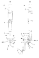
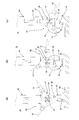
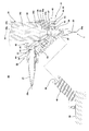
- FIG. 1 is a front view showing a coating apparatus including a nozzle device with an exchange function according to the first embodiment of the present invention.
- FIGS. 2A and 2B are diagrams illustrating a discharger including the nozzle device with a replacement function according to the first embodiment, in which FIG. 2A is an enlarged front view and FIG. 2B is a partial cross-sectional enlarged side view.
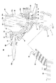
- 3A and 3B are diagrams illustrating the nozzle device with an exchange function according to the first embodiment, in which FIG. 3A is an enlarged front view of the nozzle with an exchange function, and FIG. 3B is an enlargement of the nozzle device with an exchange function.
- Sectional drawing (c) is an enlarged rear view of a nozzle with an exchange function.
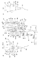
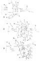
- FIG. 4 is a view for explaining a procedure for replacing a nozzle using the nozzle device with a replacement function according to the first embodiment.
- FIG. 4 (a) shows that the nozzle with a replacement function is a member to be engaged.
- FIG. 4B is a partial cross-sectional side view of FIG.
- FIG. 5 is a diagram for explaining a procedure for replacing a nozzle using the nozzle device with a replacement function according to the first embodiment, and FIG. 5 (a) shows that the nozzle with a replacement function is a member to be engaged.
- FIG. 5B is a partial cross-sectional side view of FIG. FIG.
- FIG. 6 is a diagram for explaining a procedure for replacing a nozzle using the nozzle device with a replacement function according to the first embodiment.
- FIG. 6 (a) shows an engagement portion of the nozzle device with a replacement function.
- FIG. 6B is a partial cross-sectional side view of FIG. 6A, showing a state where the engaged portion is engaged.
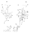
- FIG. 7 is a view for explaining a procedure for replacing the nozzle using the nozzle device with a replacement function according to the first embodiment, and FIG. 7 (a) shows an engagement portion of the nozzle device with a replacement function.
- FIG. 7B and FIG. 7C are front views showing a state in which the base part is rotated from the state of FIG. 7A. It is.
- FIG. 8 is a view for explaining a procedure for replacing a nozzle using the nozzle device with a replacement function according to the first embodiment, and FIGS. 8A and 8B are FIGS. ) Is a front view showing a state in which the base is rotated and moved from the state, and FIG. 8C is a front view showing a state in which the nozzle is replaced.
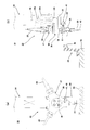
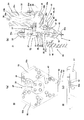
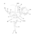
- FIG. 9 is a view showing a nozzle device with a replacement function according to the second embodiment of the present invention
- FIG. 9 (a) is an enlarged front view of the nozzle with a replacement function
- FIG. 9 (b) is a nozzle device with a replacement function.
- FIG. 9C is an enlarged bottom view of the nozzle with an exchange function.
- FIG. 9 is a view showing a procedure for replacing a nozzle using the nozzle device with a replacement function according to the first embodiment
- FIGS. 8A and 8B are FIGS. ) Is a front view showing a state in which the base is rotated
- FIG. 10 is an enlarged cross-sectional view of a nozzle with a replacement function included in a nozzle device with a replacement function according to a third embodiment of the present invention.
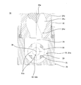
- FIG. 11 is an enlarged cross-sectional view of a nozzle device with an exchange function according to a fourth embodiment of the present invention.
- FIG. 12 is an enlarged cross-sectional view of a nozzle device with a replacement function according to the fifth embodiment of the present invention.
- FIG. 13 is an enlarged front view of the nozzle with a replacement function with which the nozzle apparatus with a replacement function which concerns on 6th Embodiment of this invention is provided.
- FIG. 14 is an enlarged cross-sectional view of a nozzle device with an exchange function according to a seventh embodiment of the present invention.
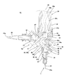
- FIG. 15A and 15B show a nozzle with a replacement function included in the nozzle device with a replacement function according to the seventh embodiment, where FIG. 15A is an enlarged front view and FIG. 15B is an enlarged rear view.
- 16 is an AA enlarged sectional view of the nozzle with a replacement function shown in FIG.
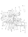
- FIG. 17 is a view showing an example of a conventional coating apparatus, in which FIG. 17 (a) is a perspective view and FIG. 17 (b) is a longitudinal sectional view showing an internal structure.
- the coating device 17 has a discharger 18 attached to the tip of an articulated robot arm 19, and the robot 20 uses the discharger 18 to
- the component member 21 or the like can be applied with a fluid such as a vibration damping agent, a sealant, or an adhesive, or can be filled with a fluid such as grease (including a fluid).
- the robot arm 19 shown in FIG. The fluid discharged from the discharger 18 can be automatically applied to the application surface 21a.
- the application device 17 can operate the nozzle 22 with an exchange function included in the discharger 18 attached to the tip of the robot arm 19 by operating the robot arm 19, Among the first to third nozzles 23, 23, 23 provided in the nozzle 22 with the replacement function, the desired nozzle 23 is rotated to a predetermined discharge position T, and the nozzle at the discharge position T The fluid can be discharged from 23.
- the discharger 18 has a discharge pump 24, a rotation drive unit (electric motor such as a servo motor) 25 for driving the discharge pump 24, and an exchange function. And a nozzle 22.
- the discharge pump 24 has, for example, a transfer pipe (not shown) connected to the suction port 26, and a fluid such as a vibration damping agent is supplied to the suction port 26 of the discharge pump 24 through the transfer pipe. It is configured as follows. Then, when the discharge pump 24 is operated, the fluid can be discharged from the nozzle 23 at the predetermined discharge position T of the nozzle 22 with the replacement function.
- the discharge pump 24 is, for example, a vertical uniaxial eccentric screw pump, and includes a rotor 24a and a stator 24b.
- the rotor 24a has a male screw shape, and is rotatably attached to a stator 24b having a female screw-shaped inner hole 24c. And the upper end of this rotor 24a is connected with the rotating shaft of the rotational drive part 25 via the connecting rod, the reduction gear, etc. which are not shown in figure.
- the plurality of first, second, and third nozzles 23 are attached to the nozzle 22 with an exchange function.
- a rotating portion 27 and a base portion 28 that rotatably holds the rotating portion 27 are provided.
- the nozzle 22 with an exchange function allows the fluid supplied from the fluid supply port 29 of the base portion 28 to pass through the desired nozzle 23 (for example, the first nozzle shown in FIG. In order to discharge from the two nozzles 23), the desired nozzle 23 can be rotationally moved to a predetermined discharge position T (lower position).
- the nozzle 22 with the replacement function includes the first to third nozzles 23,...
- the fluid such as the vibration damping agent is applied to the component member 21 or the like, for example, in a linear shape.
- the thickness of the coating line can be changed to, for example, a thick line, a medium line, and a thin line in accordance with a predetermined standard.
- Each of the thick, medium, and thin coating lines is formed by the fluid ejected by the corresponding first to third nozzles 23.
- the base part 28 with which this nozzle 22 with an exchange function is provided has the base main body 28a and the joint block 28b, as shown to Fig.3 (a), (b).
- the base body 28a is substantially columnar and has a substantially cylindrical outer peripheral surface 30.
- the base body 28 a is fastened and fixed to the joint block 28 b with bolts 31, and the joint block 28 b is screwed onto the outlet port 32 of the discharge pump 24.
- the rotating portion 27 provided in the nozzle 22 with the replacement function is formed in a substantially triangular annular shape, and the base body 28a is fitted in the center thereof.
- the rotating portion 27 is rotatable with respect to the base body 28a.
- a substantially cylindrical inner peripheral surface 33 is formed at the center of the annular rotating portion 27, and the inner peripheral surface 33 is rotatably fitted to the outer peripheral surface 30 of the base body 28a. ing.
- the first to third nozzles 23,... Having different diameters of the discharge ports 23a are attached to the three apexes of the substantially triangular rotating unit 27, respectively.
- Each of these three nozzles 23 has a large, medium, and small diameter of the discharge port 23a, and each is screwed into a nozzle mounting port formed in the rotating portion 27 via an adapter 34. Attached.
- the joint block 28b is formed with a first communication path 35, and the base body 28a is formed with a second communication path 36.
- the three third communication passages 37 are formed.
- the first and second communication paths 35 and 36 are L-shaped flow paths, and the third communication path 37 is a linear flow path.
- the first communication path 35 has a fluid supply port 29.
- the fluid supply port 29 is connected to an outlet 24d formed at the lower end of the inner hole 24c of the stator 24b.
- the fluid supply port 29 and the central axis 38 of the outflow port 24d coincide with each other.
- the outflow port 35a of the 1st communicating path 35 is connected with the inflow port 36a of the 2nd communicating path 36, and the central axis 39 of these outflow ports 35a and the inflow port 36a mutually corresponds.
- the central axis 39 of the inflow port 36a coincides with the central axis of the base body 28a, and the central axis 39 of the base body 28a serves as the central axis of rotation of the rotating portion 27.
- the outflow port 36b of the 2nd communicating path 36 is extended toward the perpendicular downward direction, as shown in FIG.3 (b), and is opened by the outer peripheral surface 30 of the base main body 28a.
- the flow of the third communication passage 37 communicating with the second nozzle 23 is formed so as to communicate with the outflow port 36 b of the second communication path 36.
- the inlet 37 a of the third communication path 37 is formed on the inner peripheral surface 33 of the rotating portion 27.
- the center axis 40 of the outflow port 36b of the 2nd communicating path 36 and the inflow port 37a of the 3rd communicating path 37 mutually corresponds, Moreover, this center axis 40 is the adapter hole formed in the adapter 34, and This coincides with the central axis of each nozzle hole formed in the second nozzle 23.
- each of the first and third nozzles 23 rotates and moves to a discharge position T directed downward in the vertical direction, each of the first and third nozzles 23 communicated with the first and third nozzles 23.
- the inlet 37 a (the rotation part 27 side) of the third communication passage 37 is formed so as to communicate with the outlet 36 b (the base body 28 a side) of the second communication passage 36.
- the inlets 37 a and 37 a of the third communication passages 37 and 37 are formed on the inner peripheral surface 33 of the rotating portion 27.
- the outflow port 36b of the second and third communication passages 36 and 37 and the central axis 40 of the inflow port 37a coincide with each other.
- the central axis 40 is formed so as to coincide with the respective central axes of the adapter hole formed in the adapter 34 and the nozzle holes formed in the first and third nozzles 23.
- the lock mechanism 41 can release the rotation of the rotating portion 27 relative to the base portion 28 when each of the first to third nozzles 23 is rotated to the discharge position T as shown in FIG. And has three lock recesses 42, a lock ball 43, and a spring portion 44.
- the second nozzle 23 is at the discharge position T, and the discharge position T is a position where the nozzle 23 is directed vertically downward.
- three lock recesses 42 are formed on the surface of the rotating portion 27 on the surface facing the joint block 28b, and the lock balls 43 are detachable in size and It is formed in a shape (conical shape). Further, the three lock recesses 42 are formed at positions where the nozzles 23 can be locked at the discharge position T when the first to third nozzles 23 are rotationally moved to the discharge position T.
- the lock ball 43 is accommodated in an accommodation hole 45 formed in the joint block 28b.
- the spring portion 44 biases the lock ball 43 toward the lock recess 42 and is accommodated in the accommodation hole 45.
- the spring portion 44 is locked by a bolt 46 with a repulsive force of the urging force, and the bolt 46 is screwed into the accommodation hole 45 and fixed.
- the spring portion 44 urges the lock ball 43 toward the lock recess 42, and when the lock ball 43 is engaged with any of the lock recesses 42, the lock ball 43 causes the rotating portion to move.
- the rotation of 27 relative to the base portion 28 can be locked. Accordingly, each of the first to third nozzles 23 can be accurately positioned and stopped at the predetermined discharge position T, and the nozzle 23 at the discharge position T is not displaced from the discharge position T. It can be releasably locked. And if the rotation part 27 is rotated against the force of the spring part 44, the lock ball 43 can be removed from the lock recess 42, and in this state, the rotation part 27 can be easily rotated, Another desired nozzle 23 can be moved to the discharge position T and locked.
- the lock mechanism 41 has the configuration shown in FIG. 3B, instead of this, the lock recess 42 is formed in the joint block 28b, and the receiving hole 45 is formed in the rotating portion 27.
- the lock ball 43, the spring portion 44, and the bolt 46 may be disposed in the hole 45.
- the nozzle 22 with an exchange function, the engaging portion 47, and the engaged portion 48 constitute the nozzle device 16 with an exchange function.
- the engaging portion 47 is a substantially cylindrical convex portion, is a front surface of the rotating portion 27, and has a diameter of the discharge port 23 a.
- the second nozzle 23 is provided at a portion to which the second nozzle 23 is attached, and is disposed at a position away from the central axis 39 of rotation of the rotation unit 27.
- the engaged portion 48 is a substantially cylindrical recess as shown in FIG. 3B, and is formed in the front portion of the upper end portion of the engaged member 49.
- the engaged portion 48 is formed in such a size that the engaging portion 47 can be engaged and disengaged.
- the engaged member 49 is, for example, as shown in FIG. 1, on the upper surface of a mounting base (fixed side portion) 50 on which the automobile component 21 or the like to be applied with a fluid such as a vibration damping agent is placed. It is attached.
- the engaging portion 47 is formed as a convex portion and the engaged portion 48 is formed as a concave portion. Instead, the engaging portion 47 is formed as a concave portion.
- the engaged portion 48 may be formed as a convex portion.
- a discharger 18 is attached to the tip of an articulated robot arm 19.
- a nozzle 22 with a replacement function is attached to the tip end (lower end) of the discharge pump 24 provided in the discharge machine 18, and among the first to third nozzles 23 attached to the nozzle 22 with a replacement function.
- the third nozzle 23 having a small diameter of the discharge port 23a is set at the discharge position T.
- the robot arm 19 is operated by a program to move the third nozzle 23 at the discharge position T to the starting point of the application surface 21a, and the discharge pump 24 is driven and the discharge machine 18 (with an exchange function).
- the nozzle 22) is moved by the robot arm 19.
- the fluid can be applied to the application surface 21a of the automobile component 21 using the third nozzle 23 in advance.
- the coating line formed by discharging the fluid from the third nozzle 23 is a thin line.
- the operation of the robot arm 19 and the driving of the discharge pump 24 are performed by a preset program, and this program is stored in advance in a storage unit of an arithmetic control unit (not shown).
- the second nozzle 23 having a medium diameter of the discharge port 23 a is used to obtain a medium A procedure for forming a coating line having a thickness will be described. That is, now, as shown in FIGS. 4A and 4B, the third nozzle 23 of the nozzle 22 with the replacement function is at the discharge position T. Then, the procedure for rotating the second nozzle 23 to the discharge position T from this state as shown in FIG.
- the robot arm 19 is operated to engage the engaging portion 47 and the engaged member.
- the robot arm 19 is operated by a program to move the second nozzle 23 at the discharge position T to the next start point of the coating surface 21a, and the discharge pump 24 is driven and the discharge machine 18 (exchange)
- the nozzle 22 with function is moved by the robot arm 19.
- the coating line formed by discharging the fluid from the second nozzle 23 is a medium thickness line. As a result, a thin coating line and a medium-thickness coating line can be formed on the coating surface 21 a of the constituent member 21.
- the desired nozzle 23 among the first to third nozzles 23, As described above, according to the nozzle device 16 with an exchange function shown in FIGS. 3A, 3B, and 3C, the desired nozzle 23 among the first to third nozzles 23,.
- T By rotating and moving to T, for example, a thick line, a medium line, and a thin line can be formed on the coating surface 21a of the component member 21 in accordance with a predetermined standard. Therefore, in order to form thick, medium, and thin coating lines, the operator needs to replace the discharge pump 24 with three types of nozzles corresponding to the thickness of the coating line. Therefore, it is possible to improve the work efficiency of the coating work.
- the nozzle replacement drive mechanism for rotating the desired nozzle 23 to the discharge position T and the nozzle movement for moving the desired nozzle 23 to apply the fluid to the coating surface 21a.
- the functions of both drive mechanisms of the drive mechanism can be shared by the robot arm 19 (nozzle movement drive mechanism). Thereby, the bulk of the coating device 17 can be reduced and the cost can be reduced.
- the second and third communication passages 36 and 37 pass through the substantially cylindrical inner peripheral surface 33.
- the portions (outer peripheral surface 30 and inner peripheral surface 33) to which the fluid pressure is applied in the second and third communication passages 36 and 37 are circumferential surfaces, so that a uniform internal pressure distribution without deviation is obtained. As a result, the sealing performance can be ensured without deteriorating the sealing performance. Therefore, fluid leakage can be easily prevented.
- the engaging portion 47 is a substantially cylindrical convex portion
- the engaged portion 48 is a substantially cylindrical concave portion that can be freely engaged with and disengaged from the convex portion of the engaging portion 47. It is as.
- the engaging portion 47 and the engaged portion 48 in such a shape, the engaging portion 47 can be easily moved relative to the engaged portion 48 using a nozzle moving drive mechanism such as the robot arm 19. Moreover, it can be securely engaged and disengaged. 7 and 8, with the engaging portion 47 engaged with the engaged portion 48, the engaging portion 47 and the engaged portion 48 that are engaged with each other are used as the center.
- the desired nozzle 23 can be easily rotated to the discharge position T by rotating the base 28.
- the fluid outlet 24d of the discharge pump 24 is disposed close to the nozzle 22 with an exchange function. Can do. As a result, the deviation between the operation timing of the discharge pump 24 and the discharge timing at which fluid is discharged from the nozzle 23 at the discharge position T can be reduced, whereby the flow rate can be accurately controlled, The fluid can be applied to the prescribed application position with high accuracy.
- FIGS. 9 (a), (b), and (c) a second embodiment of the nozzle device with an exchange function according to the present invention will be described with reference to FIGS. 9 (a), (b), and (c).
- the nozzle device 51 with an exchange function according to the second embodiment can be used by being attached to the coating device 17 instead of the nozzle device 16 with an exchange function according to the first embodiment shown in FIG.
- the difference from the nozzle device 16 with a function is that the nozzle device 16 with a replacement function according to the first embodiment shown in FIGS. 3A, 3B, and 3C is used for each of the first to third nozzles 23. While the shape of the discharge port 23a is circular, in the nozzle device 51 with an exchange function of the second embodiment shown in FIGS. 9A, 9B and 9C, the first to third nozzles
- the shape of the 52 discharge ports 52a is an elongated rectangle.
- the central axis 40 of each of the third communication passages 37 is the central axis of each of the first to third nozzles 52,.
- the difference from the first embodiment is also different from the first embodiment. Since other than this is the same as that of the first embodiment, the equivalent parts are denoted by the same reference numerals and the description thereof is omitted.
- Each of the first to third nozzles 52 provided in the nozzle 53 with an exchange function shown in FIGS. 9A, 9B, and 9C has an elongated rectangular shape of the discharge port 52a.
- the fluid can be applied in a strip shape.
- the dimension d in the thickness direction of the discharge port 52a of each of the first to third nozzles 52 is large, medium, and small.
- the fluid is discharged from the first to third nozzles 52, and the thicknesses of the strip-shaped application bodies formed on the application surface 21a become large, medium, and small as defined in advance. Can be.
- the nozzle device 55 with a replacement function of the third embodiment can be used by being attached to the coating device 17 instead of the nozzle device 16 with a replacement function of the first embodiment shown in FIG.
- the nozzle device 16 with a replacement function of the first embodiment includes a central axis 40 of the discharge port 23a of the nozzle 23 at the discharge position T, and a first communication path.
- the central axis 38 of the fluid supply port 35 (the central axis 38 of the outlet 24d of the discharge pump 24) is spaced from each other by a distance K.
- the central axis 38 of the discharge port 23a of the nozzle 23 at the discharge position T and the central axis 38 of the fluid supply port 29 of the first communication path 35 (the central axis 38 of the outlet 24d of the discharge pump 24). are arranged on the same or substantially the same straight line It is filtered off.
- the nozzle 56 with an exchange function is attached to the robot arm 19 (nozzle movement drive mechanism), and the nozzle 23 at the predetermined discharge position T is moved along the path defined on the application surface 21a.
- the fluid discharged from the nozzle 23 at the discharge position T is applied to the position defined on the application surface 21a, each of the different shapes can be obtained even when there are a large number of nozzles 56 having different functions.
- the point extending in a direction forming a predetermined angle with respect to the central axis is also different from the first embodiment. Since other than this is the same as that of the first embodiment, the equivalent parts are denoted by the same reference numerals and the description thereof is omitted.
- the nozzle device 58 with a replacement function of the fourth embodiment can be used by being attached to the coating device 17 instead of the nozzle device 55 with a replacement function of the third embodiment shown in FIG.
- the difference between the nozzle device 58 with an exchange function of the fourth embodiment shown in FIG. 11 and the nozzle device 55 with an exchange function of the third embodiment shown in FIG. 10 is the exchange of the third embodiment shown in FIG.
- the first to third communication passages 35, 36, and 37 that allow the inflow port of the nozzle 23 at the discharge position T and the fluid supply port 29 of the first communication passage 35 to communicate with each other are bent.
- the inlet of the nozzle 23 at the discharge position T and the fluid supply port 29 of the first communication path 35 are provided in the nozzle device 58 with an exchange function of the fourth embodiment shown in FIG. 11, the inlet of the nozzle 23 at the discharge position T and the fluid supply port 29 of the first communication path 35 are provided.
- the first and third communication passages 35 and 37 communicating with each other are formed on a straight line or a substantially straight line.
- the second communication path 36 is not formed.
- the discharge pump 24 for discharging the fluid from the nozzle 23 in the discharge position T can be reduced in size.
- the lengths of the first and third communication passages 35 and 37 can be shortened, the deviation between the operation timing of the discharge pump 24 and the discharge timing at which the fluid is discharged from the nozzle 23 at the discharge position T is reduced. As a result, the flow rate can be controlled with high accuracy, and the fluid can be applied to the prescribed application position with high accuracy.
- the nozzle device 58 with a replacement function of the fourth embodiment shown in FIG. 11 and the nozzle device 55 with a replacement function of the third embodiment shown in FIG. That is, in the nozzle device 55 with an exchange function of the third embodiment shown in FIG. 10, the substantially cylindrical outer peripheral surface 30 formed on the base body 28a is substantially formed at the center of the annular rotating portion 27. Whereas the cylindrical inner peripheral surface 33 is rotatably fitted, in the nozzle device 58 with an exchange function of the fourth embodiment shown in FIG. 11, the substantially truncated cone shape formed on the base portion 60.
- the outer side surface 61 is different in that a substantially frustoconical inner side surface 62 formed at the center of the annular rotation portion 64 is rotatably fitted.
- the first and third communication passages 35 and 37 that connect the inflow port of the nozzle 23 at the discharge position T and the fluid supply port 29 to each other are based on the basic structure.
- the outer side surface 61 formed on the base 28 and the inner side surface 62 formed on the rotating portion 64 are formed.
- the rotating part 64 is attached to the base part 60 via the bearing part 63 so as to be freely rotatable.
- the substantially frustoconical annular outer side surface 61 formed in the base portion 60 and the substantially frustoconical annular inner side surface 62 formed in the rotating portion 64 are connected to the first and third communication paths. 35 and 37 pass through, the outer side surface 61 of the base portion 60 and the inner side surface 62 of the rotating portion 64 are connected to the inlet port of the nozzle 23 at the discharge position T and the fluid supply port 29. Design for placement in between becomes easy.
- the central axis 38 of the discharge port 23a of the nozzle 23 at the discharge position T and the central axis 38 of the fluid supply port 29 are positioned on the same or substantially the same straight line, or the first and third communication paths 35, It is possible to easily form 37 on a straight line or a substantially straight line.
- the third embodiment is the same as the third embodiment, and the equivalent parts are denoted by the same reference numerals and the description thereof is omitted.
- the nozzle device 65 with a replacement function of the fifth embodiment shown in FIG. 12 is replaced with the circular third nozzle 23 having a small discharge port 23a in the nozzle device 58 with a replacement function of the fourth embodiment shown in FIG.
- the discharge port 52a is provided with an elongated rectangular third nozzle 52, and includes a nozzle 66 with a replacement function.
- the rectangular third nozzle 52 having an elongated discharge port 52a is the same as the third nozzle 52 attached to the nozzle device 51 with an exchange function of the second embodiment shown in FIG. 9B.
- the fourth embodiment is the same as the fourth embodiment. Therefore, the same parts are denoted by the same reference numerals and the description thereof is omitted.
- FIG. 13 shows a sixth embodiment of the nozzle device with an exchange function according to the present invention.
- the nozzle device 67 with a replacement function of the sixth embodiment is different from the nozzle device 16 with a replacement function of the first embodiment shown in FIG. 3A in place of the circular first nozzle 23 having a large discharge port 23a.
- the outlet 52a is provided with a first nozzle 52 having an elongated rectangular shape, and is provided with a nozzle 68 with an exchange function.
- the rectangular first nozzle 23 having an elongated discharge port 52a is equivalent to the first nozzle 52 having a large discharge port 52a attached to the nozzle device 51 with an exchange function of the second embodiment shown in FIG. Is.
- a linear coating line and a strip-shaped coating body can be formed on the coating surface 21a of the component member 21 without changing the nozzles 23 and 52 to the discharge pump 24. Therefore, the work efficiency of the application work can be improved.
- the second embodiment is the same as the first embodiment. Therefore, the equivalent parts are denoted by the same reference numerals and the description thereof is omitted.
- the nozzle device 73 with an exchange function according to the seventh embodiment can be used by being attached to the coating device 17 instead of the nozzle device 16 with an exchange function according to the first embodiment shown in FIG.
- the difference between the nozzle device 73 with a replacement function of the seventh embodiment shown in FIG. 14 and the nozzle device 16 with a replacement function of the first embodiment shown in FIG. 3 is as follows.
- the nozzle device 16 with an exchange function of the first embodiment shown in FIG. 3 selects a desired nozzle 23 among the first, second, and third nozzles 23,.
- the selected desired nozzle 23 is rotated to a predetermined discharge position T (lower position) and fluid is transferred from the desired nozzle 23 rotated to the discharge position T. Can be discharged.
- the nozzle device 73 with an exchange function of the seventh embodiment shown in FIGS. 14 and 15 has a plurality of first and second discharge positions, for example, as shown in FIG. Third discharge positions T1, T2, and T3 are determined. Then, a desired nozzle 23 is selected from the three first, second, and third nozzles 23,..., And the selected desired nozzle 23 is moved to three predetermined ejection positions T1, T2, T3. Among them, the fluid can be discharged from the desired nozzle 23 that is rotated to the desired discharge position and rotated to the desired discharge position. This is the difference from the first embodiment.
- the second embodiment is the same as the first embodiment. Therefore, the equivalent parts are denoted by the same reference numerals and the description thereof is omitted.
- the nozzle 74 with an exchange function according to the seventh embodiment is attached with three first, second, and third nozzles 23, as in the first embodiment.
- This exchange function-equipped nozzle 74 supplies the fluid supplied from the fluid supply port 29 of the joint block 76 to the desired nozzle 23 (for example, the second nozzle 23 shown in FIG. 14) among the first to third nozzles 23. ),
- the desired nozzle 23 is rotationally moved to a desired discharge position (eg, the lower position T1 shown in FIG. 14) among the three predetermined discharge positions T1, T2, and T3.
- the fluid can be discharged from the desired nozzle (for example, the second nozzle 23 shown in FIG. 14) that has been rotated to the desired discharge position T1.
- the three predetermined discharge positions T1, T2, and T3 are defined around the central axis 39 of the base main body 75 at intervals of 120 °.
- the position is directed vertically downward, and T2 is a position rotated by 120 ° counterclockwise from the position of T1.
- T3 is a position that is rotated clockwise by 120 ° from the position of T1.
- three discharge positions T1, T2, and T3 are defined, but a plurality of other discharge positions can be defined.
- the three discharge positions T1, T2, and T3 are defined at equal intervals of 120 °, but the respective discharge positions can be defined at different intervals.
- prescribing these discharge positions can be performed by a program stored in first and second lock mechanisms 41 and 77, which will be described later, and an arithmetic control unit.
- the base body 75 provided in the nozzle 74 with an exchange function has a substantially cylindrical shape, and a rotating portion 27 is rotatably fitted to the outer end of the base body 75.
- a joint block 76 is rotatably fitted to the center of the base body 75, and a disk member 78 is fixedly attached to the rear end surface of the base body 75 with bolts 79.
- the joint block 76 is attached to the outflow port 32 of the discharge pump 24 by screwing.
- the rotating portion 27, the first to third nozzles 23,... Provided in the nozzle 74 with an exchange function, and the mounting structure between the rotating portion 27 and the base main body 75. Since this is equivalent to the first embodiment, the description thereof is omitted.
- the joint block 76 provided in the nozzle 74 with an exchange function has a through hole formed in the center in the horizontal direction, and the through hole is formed by a substantially cylindrical inner peripheral surface 80. And the outer peripheral surface 30 of the base main body 75 is rotatably fitted to this inner peripheral surface 80.
- the joint block 76 is formed with a first communication path 81
- the base body 75 is formed with a second communication path 82
- the rotating portion 27 has 3 Two third communication passages 37 are formed.
- the first communication path 81 has a fluid supply port 29, and the fluid supply port 29 is connected to an outlet 24 d formed at the lower end portion of the inner hole 24 c of the stator 24 b.
- the fluid supply port 29 and the central axis 38 of the outflow port 24d coincide with each other.
- the outflow port 81 a of the first communication path 81 communicates with the inflow port 82 a of the second communication path 82.
- the central axis 39 of the second communication passage 82 coincides with the central axis of the base body 75, and the central axis 39 of the base body 75 serves as the central axis of rotation of the rotation unit 27. Yes.
- the outflow port 36 b of the second communication passage 82 extends vertically downward and opens at the outer peripheral surface 30 of the base body 75.
- FIG. 16 is a cross-sectional view of the first communication passage 81 shown in FIG. 14 as viewed from the AA direction.
- the first communication path 81 formed in the joint block 76 includes a fluid supply port 29 and an outflow port 81 a communicating with the fluid supply port 29.
- the outlet 81 a of the first communication path 81 is a substantially annular inner peripheral groove and is formed on the inner peripheral surface 80 of the through hole formed in the joint block 76.
- the 2nd communicating path 82 formed in the base main body 75 is provided with the radial direction flow path as the inflow port 82a, and the L-shaped center flow path 82b, as shown in FIG. .
- four inflow ports 82a are formed as radial flow paths at 90 ° intervals along the circumferential direction of the substantially central outer peripheral surface 30 of the substantially cylindrical base body 75, and each of the four inflow ports 82a is formed.
- the outer end portion is formed at a position overlapping the outlet 81 a of the first communication path 81.
- the inner end portions of the four inflow ports 82a communicate with the central flow path 82b.
- the base body 75 rotates around the central axis 39 and is discharged to any rotational position.
- Fluid discharged from the outlet 24d of the pump 24 is supplied to the fluid supply port 29, the outlet 81a (inner circumferential groove) of the first communication path 81, the inlet 82a (radial direction flow path) of the second communication path 82, and
- the fluid can be supplied to the third communication passage 37 through the central flow path 82 b, and the fluid can be discharged from the nozzle 23.
- the first locking mechanism 41 is equivalent to the locking mechanism 41 shown in FIG.
- the base body 75 shown in FIG. 14 rotates about the central axis 39, and the outlet 36b of the second communication passage 82 is the nozzle shown in FIG.
- a recess 42, a lock ball 43, and a spring portion 44 are provided.
- the outlet 36b of the second communication passage 82 is rotationally moved to the discharge position (communication position) T1, and this outlet 36b is communicated with the nozzle 23 that is rotationally moved to the discharge position T1. ing.
- the desired nozzle 23 is rotated to the discharge position T2 or T3 shown in FIG.
- the desired nozzle 23 is rotationally moved to the discharge position T2 or T3.
- the first lock mechanism 41 can lock the nozzle 23 at the discharge position T2 or T3.
- the base body 75 is rotated around the central axis 39, and the outlet 36b of the second communication passage 82 is rotated to the discharge position (communication position) T2 or T3.
- the second lock mechanism 77 can lock the outlet 36b of the second communication passage 82 at the discharge position T2 or T3.
- the outflow port 36b of the second communication path 82 can be communicated with the nozzle 23 that is rotationally moved to the discharge position T2 or T3.
- the fluid discharged from the discharge pump 24 can be discharged from the desired nozzle 23 at the desired discharge position T2 or T3.
- the second lock mechanism 77 will be described. As shown in FIG. 14, three lock recesses 42 are formed on the inner surface of the disk member 78 on the side facing the joint block 76, and the lock balls 43 are detachably formed. Further, the three lock recesses 42 are formed at positions where the outlet 36b of the second communication passage 82 can be locked at the three discharge positions T1, T2, and T3.
- the lock ball 43 is accommodated in the accommodation hole 45 formed in the joint block 76.
- the spring portion 44 is accommodated in the accommodation hole 45.
- the spring portion 44 urges the lock ball 43 toward the lock concave portion 42, and the spring portion 44 is engaged with a repulsive force of the urging force by a bolt 46. It is fixed by screwing.
- the spring portion 44 urges the lock ball 43 toward the lock recess 42, and when the lock ball 43 engages any of the lock recesses 42, the lock ball 43 43 can stop the disk member 78 from rotating relative to the joint block 76.
- the outlet 36b of the second communication path 82 can be accurately positioned and stopped at each of the three discharge positions T1, T2, T3, and the second communication path at each of the discharge positions T1, T2, T3.
- 82 outflow ports 36b can be releasably locked so as not to deviate from the discharge position.
- the base body 75 can be easily rotated,
- the outflow port 36b of the second communication passage 82 can be moved and locked to another discharge position.
- the second lock mechanism 77 is configured as shown in FIG. 14, but instead, the lock recess 42 is formed in the joint block 76, and the receiving hole 45 is formed in the disc member 78.
- a lock ball 43, a spring portion 44, and a bolt 46 may be arranged in 45.
- the first and second engaging portions 47 and 83 and the engaged portion 48 included in the nozzle device 73 with an exchange function shown in FIG. 14 will be described.
- the first engaging portion 47 and the engaged portion 48 are the same as the engaging portion 47 and the engaged portion 48 shown in FIG.
- the second engaging portion 83 shown in FIG. 14 is used in the same manner as the engaging portion 47 shown in FIG. 3, and the outflow port 36b of the second communication passage 82 is desired among the three discharge positions T1, T2, and T3. It can be rotated to the discharge position.
- the nozzle 74 with an exchange function, the first and second engaging portions 47 and 83, and the engaged portion 48 constitute a nozzle device 73 with an exchange function.
- the second engaging portion 83 is a substantially cylindrical convex portion having the same shape and size as the first engaging portion 47, and is connected to the engaged portion 48. On the other hand, it can be detachably engaged.
- the second engaging portion 83 is provided on the outer surface of the disk member 78, and from the central axis 39 of rotation of the rotating portion 27 when the outlet 36b of the second communication passage 82 is at the discharge position T1. It is located at a position directly below it.
- the second engaging portion 83 is attached to the outer surface of the disk member 78 on the side opposite to the outer surface of the rotating portion 27 to which the first engaging portion 47 is attached. Therefore, when the second engaging portion 83 is engaged with the engaged portion 48 of the engaged member 49 provided on the mounting table 50, the second engaging portion 83 is engaged with the engaged portion 48. It is necessary to go to.
- the second engaging portion 83 can be directed to the engaged portion 48 by turning the tip of the robot arm 19 by 180 ° about the vertical line. Further, when the second engaging portion 83 is operated without turning the tip of the robot arm 19 by 180 °, the engaged portion (first engaged portion) 48 as shown by a two-dot chain line in FIG. In addition to the engaged member (first engaged member) 49 having the second engaging member 48, the second engaged member 84 having the second engaged portion 48 for operating the second engaging portion 83 is mounted on the platform 50. May be provided. The second engaged portion 48 is disposed in a direction facing the first engaged portion 48.
- the second engaging portion 83 is formed as a convex portion, and the engaged portion 48 is formed as a concave portion. Instead, the second engaging portion is formed as a concave portion. However, the engaged portion may be formed as a convex portion.
- the discharger of the seventh embodiment is attached to the tip of the articulated robot arm 19. Then, as shown in FIG. 14, in the nozzle 74 with an exchange function provided in the discharger, the second nozzle 23 having the inside diameter of the discharge port 23a among the first to third nozzles 23 is set to the discharge position T1. ing.
- the fluid can be applied to, for example, the application surface 21a on the upper surface of the predetermined automotive component 21 using the second nozzle 23.
- the coating line formed by discharging the fluid from the second nozzle 23 is a medium thickness line.
- an application surface (not shown) on the inner lower surface of the automobile component member 21 on which a medium-thickness application line is formed using the second nozzle 23 is further discharged, for example.
- a procedure for forming a thick coating line using the first nozzle 23 having a large diameter of the outlet 23a will be described. That is, as shown in FIGS. 14 and 15, the second nozzle 23 of the nozzle 74 with the replacement function is at the discharge position T ⁇ b> 1, and the outlet 36 b of the second communication passage 82 formed in the base body 75 is At the discharge position T1. Then, from this state, although not shown in the drawing, a procedure for rotating the first nozzle 23 to the discharge position T3 and rotating the outlet 36b of the second communication passage 82 to the discharge position T3 will be described.
- the first nozzle 23 is rotationally moved to the discharge position T3 using the same method as in the first embodiment. That is, as shown in FIG. 14, by engaging the robot arm 19, the first engagement portion 47 provided in the nozzle 74 with the exchange function is engaged with the engaged member 49 attached to the mounting table 50. Engage with the joint 48.
- the arc is moved in a predetermined direction. Accordingly, the first nozzle 23 having a large diameter of the discharge port 23a can be rotationally moved to the discharge position T3.
- the rotation unit 27 rotates around the base body 75 that is stopped.
- the base body 75 is configured not to rotate in the same direction along with the rotating portion 27.
- the configuration is realized by the second lock mechanism 77, and the second lock mechanism 77 engages and locks the base body 75 with the joint block 76. Therefore, the engagement force with which the second lock mechanism 77 engages the base body 75 and the joint block 76 with each other is set to be larger than the frictional resistance between the rotating portion 27 and the base body 75. ing.
- the outlet 36b of the second communication passage 82 is rotationally moved to the discharge position T3. That is, by operating the robot arm 19, the first engaging portion 47 shown in FIG. 14 is separated from the engaged portion 48. Then, the distal end portion of the robot arm 19 is turned by 180 °, the second engaging portion 83 is directed toward the engaged portion 48, and the second engaging portion 83 is engaged with the engaged portion 48. .
- the base body 75 rotates at the center of the rotating portion 27 that is stopped.
- the rotating portion 27 is configured not to rotate in the same direction along with the base body 75.
- the configuration is realized by the first lock mechanism 41, and the first lock mechanism 41 engages the rotating portion 27 with the joint block 76. Therefore, the engaging force with which the first lock mechanism 41 engages the rotating portion 27 and the joint block 76 with each other is set to be larger than the frictional resistance between the rotating portion 27 and the base body 75. ing.
- the robot arm 19 is operated by the program to move the first nozzle 23 at the discharge position T3 to the next starting point on the application surface of the inner lower surface of the automobile component 21 and discharge.
- the pump 24 is driven and the discharger (nozzle 74 with an exchange function) is moved by the robot arm 19. In this way, the fluid can be applied to each application surface of the automotive structural member 21 using the first nozzle 23 in advance.
- a thick line, a medium line, and a thin line can be formed on the application surface 21a of the constituent member 21 in accordance with a predetermined standard.
- the fluid can be applied by directing the nozzle 23 to various locations with different orientations such as the upper surface, the inner lower surface, and the inner and outer side surfaces of the component member 21.
- a coating line having a desired thickness can be freely applied to a coating surface formed in various directions and positions. Since it can be formed, these plural types of coating operations can be performed with extremely high work efficiency.
- a uniaxial eccentric screw pump is used as the discharge pump 24.
- another type of pump may be used instead of this.
- the discharge pump 24 is attached to the tip of the robot arm 19, and the nozzle 22 with an exchange function is attached to the outlet portion 32 of the discharge pump 24.
- the discharge pump 24 is installed on a fixed side other than the robot arm 19, and the nozzle 22 with an exchange function is attached to the tip of the robot arm 19, and the fluid discharged from the discharge pump 24 is It is good also as a structure supplied to the fluid supply port 29 of the nozzle 22 with an exchange function ... via a transfer pipe. In this way, the driving force required for the robot arm 19 can be reduced.
- the three first to third nozzles 23,... A configuration in which two or more nozzles 23 are attached may be employed.
- the first to second nozzles that communicate the inflow port of the nozzle 23 at the discharge position T and the fluid supply port 29 of the first communication path 35 with each other.
- the three communication paths 35, 36, and 37 are formed to be bent, the first to third communication paths 35, 36, and 37 may be formed as straight communication paths instead. In this case, it is necessary to increase the diameter of the base portion 28.
Landscapes
- Engineering & Computer Science (AREA)
- Robotics (AREA)
- Mechanical Engineering (AREA)
- Spray Control Apparatus (AREA)
- Coating Apparatus (AREA)
- Nozzles (AREA)
Abstract
Description
17 塗布装置
18 吐出機
19 ロボット腕
20 ロボット
21 構成部材
21a 塗布面
22、53、56、59、66、68、74 交換機能付きノズル
23、52 第1ノズル、第2ノズル、第3ノズル
23a、52a 吐出口
24 吐出ポンプ
24a ロータ
24b ステータ
24c 内孔
24d、35a、36b 流出口
25 回転駆動部
26 吸込み口
27、64 回動部
28、60 基台部
28a 基台本体
28b、76 ジョイントブロック(基台枠体)
29 流体供給口
30 基台本体の外周面
31、46 ボルト
32 吐出ポンプの流出口部
33 回動部の内周面
34 アダプタ
35 第1連通路
36 第2連通路
36a、37a 流入口
37 第3連通路
38、39、40 中心軸
41 ロック機構(第1ロック機構)
42 ロック凹部
43 ロックボール
44 バネ部
45 収容孔
47 係合部(第1係合部)
48 被係合部(第1被係合部)
49 被係合部材(第1被係合部材)
50 載台
61 基台の外側の側面
62 回動部の内側の側面
63 軸受部
70 円周
75 基台本体
77 第2ロック機構
78 円板部材
79 ボルト
80 ジョイントブロックの内周面
81 第1連通路
81a 流出口
82 第2連通路
82a 流入口
82b 中心流路
83 第2係合部
84 第2被係合部材
T、T1、T2、T3、T4 吐出位置
Claims (11)
- 複数のノズルが取り付けられている回動部を有し、この回動部を回動自在に保持する基台部が設けられ、前記基台部の流体供給口から供給される流体を、前記複数のノズルのうち所望のノズルから吐出させるために、前記所望のノズルを所定の吐出位置に回転移動させることができる交換機能付きノズルと、
前記回動部に設けた係合部と、
固定側部に設けられ前記係合部に係脱自在に係合される被係合部とを備え、
前記係合部を前記被係合部に係合させた状態で、前記基台部を移動させることによって、前記所望のノズルを前記吐出位置に回転移動させる構成としたことを特徴とする交換機能付きノズル装置。 - 前記吐出位置にある前記ノズルの吐出口の中心軸と、前記流体供給口の中心軸とが、同一又は略同一直線上に位置する構成としたことを特徴とする請求項1記載の交換機能付きノズル装置。
- 前記吐出位置にある前記ノズルの流入口と、前記流体供給口とを互いに連通させる連通路が、一直線又は略一直線上に形成されていることを特徴とする請求項1又は2記載の交換機能付きノズル装置。
- 前記基台部が略円筒形の外周面、又は略円錐台形の環状の外側の側面を有し、
前記外周面、又は前記外側の側面に対向する状態で回動可能なように前記回動部に略円筒形の内周面、又は略円錐台形の内側の側面が設けられ、
前記吐出位置にある前記ノズルの流入口と、前記流体供給口とを互いに連通する連通路が、前記基台部の外周面及び前記回動部の内周面、又は前記基台部の外側の側面及び前記回動部の内側の側面を通る構成としたことを特徴とする請求項1記載の交換機能付きノズル装置。 - 前記係合部が凸部又は凹部であり、前記被係合部は、前記係合部の凸部又は凹部に係脱自在な凹部又は凸部であることを特徴とする請求項1記載の交換機能付きノズル装置。
- 前記複数のそれぞれのノズルが前記吐出位置に回転移動したときに、前記回動部の回転を前記基台部に対して解除可能にロックするロック機構を備え、
前記ロック機構は、前記回動部及び固定側部のうちの一方に形成された複数のロック凹部、
前記回動部及び前記固定側部のうちの他方に設けられ前記ロック凹部に係合されるロックボール、及び
このロックボールを前記ロック凹部側に付勢するバネ部を有することを特徴とする請求項1記載の交換機能付きノズル装置。 - 請求項1記載の交換機能付きノズル装置と、前記交換機能付きノズルの前記流体供給口に流体を供給するポンプと、このポンプ及び前記交換機能付きノズルが取り付けられているロボット腕とを備えることを特徴とする塗布装置。
- 複数のノズルが取り付けられている回動部と、
この回動部を回動自在に保持する基台本体と、
この基台本体を回動自在に保持する基台枠体とを備え、
前記回動部は、前記基台枠体の流体供給口から供給される流体を、前記複数のノズルのうち所望のノズルから吐出させるために、前記所望のノズルを所望の吐出位置に回転移動させることができ、かつ、
前記基台本体は、前記基台枠体の流体供給口と、前記所望の吐出位置にある前記所望のノズルとを連通させるために、当該基台本体に形成されている連通路を所定の連通位置に回転移動させることができる構成としたことを特徴とする交換機能付きノズル。 - 請求項8記載の交換機能付きノズルと、
前記回動部に設けた第1係合部と、
前記基台本体に設けた第2係合部と、
固定側部に設けられ前記第1係合部及び前記第2係合部が係脱自在に係合される被係合部とを備え、
前記第1係合部を前記被係合部に係合させた状態で、前記基台本体を移動させることによって、前記所望のノズルを前記所望の吐出位置に回転移動させることができ、かつ、
前記第2係合部を前記被係合部に係合させた状態で、前記基台本体を移動させることによって、前記連通路を所望の連通位置に回転移動させることができる構成としたことを特徴とする交換機能付きノズル装置。 - 前記被係合部は、前記第1係合部及び前記第2係合部のいずれにも係脱自在に係合される1つの被係合部、又は、
前記第1係合部に係脱自在に係合される第1被係合部と、前記第2係合部に係脱自在に係合される第2被係合部との2つの被係合部で構成されていることを特徴とする請求項9記載の交換機能付きノズル装置。 - 請求項9又は10記載の交換機能付きノズル装置と、前記交換機能付きノズルの前記流体供給口に流体を供給するポンプと、このポンプ及び前記交換機能付きノズルが取り付けられているロボット腕とを備えることを特徴とする塗布装置。
Priority Applications (3)
| Application Number | Priority Date | Filing Date | Title |
|---|---|---|---|
| KR1020117007948A KR101214342B1 (ko) | 2008-10-31 | 2009-10-07 | 교환기능을 갖는 노즐, 교환기능을 갖는 노즐 장치 및 이를 구비한 도포 장치 |
| EP09823242.4A EP2347831A4 (en) | 2008-10-31 | 2009-10-07 | NOZZLE WITH REPOSITIONING FUNCTION, NOZZLE DEVICE WITH REPOSITIONING FUNCTION, AND APPLICATION DEVICE WITH NOZZLE DEVICE WITH REPOSITIONING FUNCTION |
| US13/126,016 US8561920B2 (en) | 2008-10-31 | 2009-10-07 | Variable nozzle, variable nozzle device, and applying device including variable nozzle device |
Applications Claiming Priority (2)
| Application Number | Priority Date | Filing Date | Title |
|---|---|---|---|
| JP2008281283A JP5283012B2 (ja) | 2008-10-31 | 2008-10-31 | 交換機能付きノズル、交換機能付きノズル装置及びそれを備える塗布装置 |
| JP2008-281283 | 2008-10-31 |
Publications (1)
| Publication Number | Publication Date |
|---|---|
| WO2010050127A1 true WO2010050127A1 (ja) | 2010-05-06 |
Family
ID=42128500
Family Applications (1)
| Application Number | Title | Priority Date | Filing Date |
|---|---|---|---|
| PCT/JP2009/005210 WO2010050127A1 (ja) | 2008-10-31 | 2009-10-07 | 交換機能付きノズル、交換機能付きノズル装置及びそれを備える塗布装置 |
Country Status (5)
| Country | Link |
|---|---|
| US (1) | US8561920B2 (ja) |
| EP (1) | EP2347831A4 (ja) |
| JP (1) | JP5283012B2 (ja) |
| KR (1) | KR101214342B1 (ja) |
| WO (1) | WO2010050127A1 (ja) |
Cited By (3)
| Publication number | Priority date | Publication date | Assignee | Title |
|---|---|---|---|---|
| JP2010104945A (ja) * | 2008-10-31 | 2010-05-13 | Heishin Engineering & Equipment Co Ltd | 交換機能付きノズル、交換機能付きノズル装置及びそれを備える塗布装置 |
| CN102698909A (zh) * | 2011-03-18 | 2012-10-03 | 佛吉亚汽车前端模块公司 | 喷漆装置以及使用该装置的方法 |
| CN112439590A (zh) * | 2020-11-15 | 2021-03-05 | 泰州市津达电子科技有限公司 | 一种变压器生产用表面喷粉设备 |
Families Citing this family (21)
| Publication number | Priority date | Publication date | Assignee | Title |
|---|---|---|---|---|
| JP2012005921A (ja) * | 2010-06-22 | 2012-01-12 | Toyota Motor Corp | シーラ塗布装置及びその吐出量制御方法 |
| US20130273818A1 (en) * | 2012-04-13 | 2013-10-17 | Hon Hai Precision Industry Co., Ltd. | Manipulator and polishing mechanism thereof |
| JP6120582B2 (ja) * | 2013-01-22 | 2017-04-26 | キヤノン株式会社 | 塗布システム及び塗布方法 |
| HUE057972T2 (hu) * | 2013-08-29 | 2022-06-28 | Ged Integrated Solutions Inc | Ablak tisztító rendszer és eljárás |
| JP6304617B2 (ja) | 2013-09-09 | 2018-04-04 | 兵神装備株式会社 | 流体塗布システムおよび流体塗布方法 |
| DE202013105910U1 (de) * | 2013-12-23 | 2015-03-24 | Kuka Systems Gmbh | Roboterwerkzeug |
| CN105081491A (zh) | 2014-05-15 | 2015-11-25 | 通用电气公司 | 加工系统及用于其上的刀具固持装置 |
| CN104174552B (zh) * | 2014-07-29 | 2016-08-31 | 宁波信泰机械有限公司 | 一种全自动胶筒更换装置 |
| DE202014104946U1 (de) * | 2014-10-16 | 2016-01-19 | Kuka Systems Gmbh | Werkzeugwechselvorrichtung für Manipulatoren |
| CN107206413A (zh) | 2015-02-03 | 2017-09-26 | 本田技研工业株式会社 | 涂覆装置 |
| JP2017222001A (ja) * | 2016-06-15 | 2017-12-21 | セイコーエプソン株式会社 | ロボット、制御装置およびロボットシステム |
| CN106000779A (zh) * | 2016-08-04 | 2016-10-12 | 汪锐 | 一种led灯固晶机的点胶机构 |
| CN106944626B (zh) * | 2017-04-14 | 2019-10-18 | 华南理工大学 | 一种用于汽车细密封涂覆pvc材料的复杂流管及制造方法 |
| DE102017003714A1 (de) * | 2017-04-15 | 2018-10-18 | Audi Ag | Roboteranlage mit Werkzeugfixiereinrichtung |
| CN111182977B (zh) * | 2017-10-03 | 2022-07-19 | 堺显示器制品株式会社 | 喷嘴连接器、喷嘴连接器组、涂布装置及涂布系统 |
| JP6943747B2 (ja) * | 2017-12-15 | 2021-10-06 | 株式会社ヒラノテクシード | 塗工装置 |
| JP6943748B2 (ja) * | 2017-12-15 | 2021-10-06 | 株式会社ヒラノテクシード | 塗工装置 |
| CN108672185A (zh) * | 2018-07-18 | 2018-10-19 | 伊之密机器人自动化科技(苏州)有限公司 | 自动单控水性喷涂系统 |
| CN113018488B (zh) * | 2021-02-25 | 2023-07-14 | 苏州清乐智能科技有限公司 | 高效消毒机器人 |
| BE1030467B1 (fr) * | 2022-04-20 | 2023-11-20 | Quantoom Biosciences S A | Bras robotique pour la manipulation de milieux liquides, système comprenant ledit bras robotique et méthode pour la manipulation de milieux liquides |
| KR102537806B1 (ko) * | 2022-05-17 | 2023-05-26 | 이희균 | 미사 분사구조를 갖는 도로용 잡초제거장치 |
Citations (5)
| Publication number | Priority date | Publication date | Assignee | Title |
|---|---|---|---|---|
| JPS59102170U (ja) * | 1982-12-25 | 1984-07-10 | 八条興業株式会社 | 噴口切替バルブ |
| JPH0657440U (ja) * | 1993-01-13 | 1994-08-09 | 関東自動車工業株式会社 | 回転式ノズルガン |
| JPH08224510A (ja) * | 1995-02-21 | 1996-09-03 | Mitsubishi Heavy Ind Ltd | ロボット洗浄装置及びロボット洗浄装置用ノズル |
| JP2006187715A (ja) | 2005-01-05 | 2006-07-20 | Juki Corp | 接着剤塗布装置 |
| JP2007190552A (ja) * | 1995-07-12 | 2007-08-02 | Volvo Ab | 流体塗布用装置 |
Family Cites Families (11)
| Publication number | Priority date | Publication date | Assignee | Title |
|---|---|---|---|---|
| US1554521A (en) * | 1920-06-25 | 1925-09-22 | Clarence A Bartlett | Squirt nozzle |
| US3779533A (en) * | 1972-06-15 | 1973-12-18 | B Etter | Machine mounted cutting torch |
| JPH072317B2 (ja) * | 1984-10-19 | 1995-01-18 | ソニー株式会社 | 産業用ロボツトのツール選択装置 |
| US5833147A (en) * | 1997-01-13 | 1998-11-10 | Abb Flexible Automation Inc. | Rotary union for robotic end effector |
| US6435427B1 (en) * | 2001-01-16 | 2002-08-20 | Coltec Industries, Inc. | Nozzle assembly with an extendable turret |
| US6554212B2 (en) * | 2001-02-08 | 2003-04-29 | Ipr Automation Lp | Robot spray head for cavity treatment |
| DE10115467A1 (de) * | 2001-03-29 | 2002-10-02 | Duerr Systems Gmbh | Werkzeugwechselsystem für eine Maschine |
| US6749134B2 (en) * | 2001-06-18 | 2004-06-15 | Spraying Systems Co. | Spray nozzle assembly with auxiliary high volume spray nozzle |
| JP2008175199A (ja) * | 2006-12-20 | 2008-07-31 | Heishin Engineering & Equipment Co Ltd | 一軸偏心ねじポンプ |
| US8025277B2 (en) * | 2008-02-06 | 2011-09-27 | GM Global Technology Operations LLC | Reconfigurable end-of-arm tool for robotic arm |
| JP5283012B2 (ja) * | 2008-10-31 | 2013-09-04 | 兵神装備株式会社 | 交換機能付きノズル、交換機能付きノズル装置及びそれを備える塗布装置 |
-
2008
- 2008-10-31 JP JP2008281283A patent/JP5283012B2/ja not_active Expired - Fee Related
-
2009
- 2009-10-07 US US13/126,016 patent/US8561920B2/en not_active Expired - Fee Related
- 2009-10-07 EP EP09823242.4A patent/EP2347831A4/en not_active Withdrawn
- 2009-10-07 WO PCT/JP2009/005210 patent/WO2010050127A1/ja active Application Filing
- 2009-10-07 KR KR1020117007948A patent/KR101214342B1/ko not_active IP Right Cessation
Patent Citations (5)
| Publication number | Priority date | Publication date | Assignee | Title |
|---|---|---|---|---|
| JPS59102170U (ja) * | 1982-12-25 | 1984-07-10 | 八条興業株式会社 | 噴口切替バルブ |
| JPH0657440U (ja) * | 1993-01-13 | 1994-08-09 | 関東自動車工業株式会社 | 回転式ノズルガン |
| JPH08224510A (ja) * | 1995-02-21 | 1996-09-03 | Mitsubishi Heavy Ind Ltd | ロボット洗浄装置及びロボット洗浄装置用ノズル |
| JP2007190552A (ja) * | 1995-07-12 | 2007-08-02 | Volvo Ab | 流体塗布用装置 |
| JP2006187715A (ja) | 2005-01-05 | 2006-07-20 | Juki Corp | 接着剤塗布装置 |
Non-Patent Citations (1)
| Title |
|---|
| See also references of EP2347831A4 |
Cited By (3)
| Publication number | Priority date | Publication date | Assignee | Title |
|---|---|---|---|---|
| JP2010104945A (ja) * | 2008-10-31 | 2010-05-13 | Heishin Engineering & Equipment Co Ltd | 交換機能付きノズル、交換機能付きノズル装置及びそれを備える塗布装置 |
| CN102698909A (zh) * | 2011-03-18 | 2012-10-03 | 佛吉亚汽车前端模块公司 | 喷漆装置以及使用该装置的方法 |
| CN112439590A (zh) * | 2020-11-15 | 2021-03-05 | 泰州市津达电子科技有限公司 | 一种变压器生产用表面喷粉设备 |
Also Published As
| Publication number | Publication date |
|---|---|
| EP2347831A1 (en) | 2011-07-27 |
| US20110204102A1 (en) | 2011-08-25 |
| JP5283012B2 (ja) | 2013-09-04 |
| US8561920B2 (en) | 2013-10-22 |
| EP2347831A4 (en) | 2014-11-12 |
| KR101214342B1 (ko) | 2012-12-20 |
| JP2010104945A (ja) | 2010-05-13 |
| KR20110065515A (ko) | 2011-06-15 |
Similar Documents
| Publication | Publication Date | Title |
|---|---|---|
| WO2010050127A1 (ja) | 交換機能付きノズル、交換機能付きノズル装置及びそれを備える塗布装置 | |
| KR101643215B1 (ko) | 노즐 회전 기구 및 이것을 구비하는 도포 장치 | |
| CN104541095B (zh) | 管接头 | |
| JP4885984B2 (ja) | 塗装装置 | |
| US6705537B2 (en) | Orbital applicator tool with self-centering dispersing head | |
| US11370596B1 (en) | Micro-volume dispense pump systems and methods | |
| US20230122239A1 (en) | Mixing valve assembly having an atomizing spray tip | |
| CN101670328A (zh) | 用于涂敷流体的设备 | |
| JP2007190552A (ja) | 流体塗布用装置 | |
| KR20120048741A (ko) | 공작기계용 선회형 헤드 | |
| JP2020131182A (ja) | 吐出装置及び産業用ロボット | |
| TWI737241B (zh) | 夾頭的防塵機構及夾頭 | |
| ES2923955T3 (es) | Turbina para dispositivo de proyección de fluido, dispositivo de proyección de fluido, así como conjunto que comprende dicho dispositivo y una herramienta | |
| JP2021079513A (ja) | ナットランナ装置 | |
| CN202491134U (zh) | 冷却液喷射装置 | |
| JP2014144502A (ja) | 切削液供給装置 | |
| JP2014016010A (ja) | ロータリジョイント | |
| JP5802485B2 (ja) | クーラントノズル二方向動作構造 | |
| EP2440340B1 (en) | Device for cleaning closed spaces | |
| JP2013094945A (ja) | 二方向動作クーラントノズルへの研削液供給構造 | |
| JP4739764B2 (ja) | 接着剤塗布装置 | |
| JP7328706B2 (ja) | 噴霧ノズル取付用アダプタ | |
| CN218925138U (zh) | 一种具有快拆式螺杆组件的点胶装置 | |
| JP6691179B2 (ja) | クラッチ付きギアポンプ及び塗装装置 | |
| US20020104899A1 (en) | Orbital applicator tool with static mixer tip seal valve |
Legal Events
| Date | Code | Title | Description |
|---|---|---|---|
| 121 | Ep: the epo has been informed by wipo that ep was designated in this application |
Ref document number: 09823242 Country of ref document: EP Kind code of ref document: A1 |
|
| ENP | Entry into the national phase |
Ref document number: 20117007948 Country of ref document: KR Kind code of ref document: A |
|
| NENP | Non-entry into the national phase |
Ref country code: DE |
|
| WWE | Wipo information: entry into national phase |
Ref document number: 2009823242 Country of ref document: EP |
|
| WWE | Wipo information: entry into national phase |
Ref document number: 13126016 Country of ref document: US |