WO2010047359A1 - ナトリウム二次電池 - Google Patents
ナトリウム二次電池 Download PDFInfo
- Publication number
- WO2010047359A1 WO2010047359A1 PCT/JP2009/068152 JP2009068152W WO2010047359A1 WO 2010047359 A1 WO2010047359 A1 WO 2010047359A1 JP 2009068152 W JP2009068152 W JP 2009068152W WO 2010047359 A1 WO2010047359 A1 WO 2010047359A1
- Authority
- WO
- WIPO (PCT)
- Prior art keywords
- electrode
- secondary battery
- sodium
- sodium secondary
- group
- Prior art date
- Legal status (The legal status is an assumption and is not a legal conclusion. Google has not performed a legal analysis and makes no representation as to the accuracy of the status listed.)
- Ceased
Links
Images


Classifications
-
- H—ELECTRICITY
- H01—ELECTRIC ELEMENTS
- H01M—PROCESSES OR MEANS, e.g. BATTERIES, FOR THE DIRECT CONVERSION OF CHEMICAL ENERGY INTO ELECTRICAL ENERGY
- H01M10/00—Secondary cells; Manufacture thereof
- H01M10/05—Accumulators with non-aqueous electrolyte
- H01M10/054—Accumulators with insertion or intercalation of metals other than lithium, e.g. with magnesium or aluminium
-
- H—ELECTRICITY
- H01—ELECTRIC ELEMENTS
- H01M—PROCESSES OR MEANS, e.g. BATTERIES, FOR THE DIRECT CONVERSION OF CHEMICAL ENERGY INTO ELECTRICAL ENERGY
- H01M4/00—Electrodes
- H01M4/02—Electrodes composed of, or comprising, active material
- H01M4/36—Selection of substances as active materials, active masses, active liquids
- H01M4/38—Selection of substances as active materials, active masses, active liquids of elements or alloys
- H01M4/40—Alloys based on alkali metals
-
- H—ELECTRICITY
- H01—ELECTRIC ELEMENTS
- H01M—PROCESSES OR MEANS, e.g. BATTERIES, FOR THE DIRECT CONVERSION OF CHEMICAL ENERGY INTO ELECTRICAL ENERGY
- H01M4/00—Electrodes
- H01M4/02—Electrodes composed of, or comprising, active material
- H01M4/36—Selection of substances as active materials, active masses, active liquids
- H01M4/58—Selection of substances as active materials, active masses, active liquids of inorganic compounds other than oxides or hydroxides, e.g. sulfides, selenides, tellurides, halogenides or LiCoFy; of polyanionic structures, e.g. phosphates, silicates or borates
- H01M4/581—Chalcogenides or intercalation compounds thereof
-
- H—ELECTRICITY
- H01—ELECTRIC ELEMENTS
- H01M—PROCESSES OR MEANS, e.g. BATTERIES, FOR THE DIRECT CONVERSION OF CHEMICAL ENERGY INTO ELECTRICAL ENERGY
- H01M4/00—Electrodes
- H01M4/02—Electrodes composed of, or comprising, active material
- H01M4/36—Selection of substances as active materials, active masses, active liquids
- H01M4/58—Selection of substances as active materials, active masses, active liquids of inorganic compounds other than oxides or hydroxides, e.g. sulfides, selenides, tellurides, halogenides or LiCoFy; of polyanionic structures, e.g. phosphates, silicates or borates
- H01M4/581—Chalcogenides or intercalation compounds thereof
- H01M4/5815—Sulfides
-
- Y—GENERAL TAGGING OF NEW TECHNOLOGICAL DEVELOPMENTS; GENERAL TAGGING OF CROSS-SECTIONAL TECHNOLOGIES SPANNING OVER SEVERAL SECTIONS OF THE IPC; TECHNICAL SUBJECTS COVERED BY FORMER USPC CROSS-REFERENCE ART COLLECTIONS [XRACs] AND DIGESTS
- Y02—TECHNOLOGIES OR APPLICATIONS FOR MITIGATION OR ADAPTATION AGAINST CLIMATE CHANGE
- Y02E—REDUCTION OF GREENHOUSE GAS [GHG] EMISSIONS, RELATED TO ENERGY GENERATION, TRANSMISSION OR DISTRIBUTION
- Y02E60/00—Enabling technologies; Technologies with a potential or indirect contribution to GHG emissions mitigation
- Y02E60/10—Energy storage using batteries
Definitions
- the present invention relates to a sodium secondary battery.
- a sodium secondary battery is a secondary battery having a positive electrode, a negative electrode, and a non-aqueous electrolyte.
- Secondary batteries are typically lithium secondary batteries, which have already been put into practical use as compact power sources for mobile phones and notebook computers, and are also used as power sources for automobiles and distributed power storage such as electric vehicles and hybrid vehicles. Therefore, the demand is increasing.
- a large amount of raw materials containing rare metal elements such as lithium are used, and there is concern about the supply of the raw materials to meet the increasing demand for large-scale power supplies.
- a sodium secondary battery has been studied as a secondary battery that can solve the above supply concerns.
- a sodium secondary battery In a sodium secondary battery, it is expected that a large amount of power can be supplied in large quantities by using a raw material that is abundant in supply and inexpensive.
- a conventional sodium secondary battery Journal of Electrochemical Society; Journal of Electrochemical Society; Electronic Science, Technology, Vol. 127, 1980, USA.
- a sodium secondary battery using TiS 2 as a positive electrode material and sodium metal as a negative electrode material is specifically described.
- An object of the present invention is to provide a sodium secondary battery that provides a larger discharge capacity.
- the inventors of the present invention have intensively studied to solve the above-mentioned problems and have arrived at the present invention. That is, the present invention provides ⁇ 1> to ⁇ 4>.
- a sodium secondary battery comprising a compound represented by formula (I), comprising a first electrode, a second electrode, and a non-aqueous electrolyte, wherein the first electrode can be doped and dedoped with sodium ions.
- M represents one or more selected from the group consisting of transition metal elements
- Z represents one or more selected from the group consisting of Group 16 elements in the IUPAC periodic table.
- M represents one or more selected from the group consisting of transition metal elements
- Z represents one or more selected from the group consisting of Group 16 elements in the IUPAC periodic table.
- Z includes S.
- M contains Fe.
- ⁇ 4> The sodium secondary battery according to any one of ⁇ 1> to ⁇ 3>, wherein the second electrode includes sodium metal or a sodium alloy.
- FIG. 1 is a powder X-ray diffraction pattern of the electrode active material 1.
- FIG. 2 is an SEM photograph of the electrode active material 1.
- FIG. 3 is a powder X-ray diffraction pattern of the electrode active material 2.
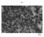
- FIG. 4 is a SEM photograph of the electrode active material 2.
- the sodium secondary battery of the present invention includes a first electrode, a second electrode, and a non-aqueous electrolyte.
- the first electrode contains a compound of formula (I) that can be doped and dedoped with sodium ions.
- M 3 Z 4 (I) M represents one or more selected from the group consisting of transition metal elements, and Z represents one or more selected from the group consisting of Group 16 elements in the IUPAC periodic table.
- This compound acts as an electrode active material of a sodium secondary battery, and usually the first electrode acts as a positive electrode.
- the molar ratio (atomic ratio) of M: Z is 3: 4.
- M represents one or more selected from the group consisting of transition metal elements, specifically, a group consisting of iron (Fe), manganese (Mn), nickel (Ni), cobalt (Co) and titanium (Ti).
- M preferably contains one or more selected from Fe, Mn and Ni, and more preferably contains Fe.
- Z represents one or more selected from the group consisting of Group 16 elements of the IUPAC periodic table, specifically oxygen (O), sulfur (S), selenium (Se), and tellurium (Te).
- S oxygen
- S sulfur
- S selenium
- Te tellurium
- M is particularly preferably Fe and Z is S.
- the compound represented by the formula (I) in which M is one kind is, for example, Fe 3 S 4 , Mn 3 S 4 , Ni 3 S 4 , Co 3 S 4 , Ti 3 S 4 , Fe 3 Se 4 , Mn 3 Se 4 , Ni 3 Se 4 , Co 3 Se 4 , Ti 3 Se 4 , and Fe 3 Te 4 , Mn 3 Te 4 , Ni 3 Te 4 , Co 3 Te 4 , Ti 3 T 4
- M is two types is, for example, (Fe, Mn) 3 S 4 , (Fe, Ni) 3 S 4 , (Fe, Co) 3 S 4 , (Fe, Ti) 3 S 4 , (Mn, Ni) 3 S 4 , (Mn, Co) 3 S 4 , (Mn, Ti) 3 S 4 , (Ni, Co) 3 S 4 , (Ni, Ti) 3 S 4 , (Co, Ti) 3 S 4 , (Fe, Mn) 3 Se 4 ,
- a part of M may be substituted with a metal element other than the transition metal element constituting M as long as the effects of the present invention are not impaired.
- the compound represented by the formula (I) is usually granular, and the shape thereof is, for example, spherical or plate-like, and is preferably spherical from the viewpoint of ease of production of the electrode.
- the compound usually has a particle size of about 10 nm to about 100 ⁇ m.
- Examples of the precursor of M 3 Z 4 include a mixture obtained by weighing and mixing an M-containing raw material and a Z-containing raw material so as to have a predetermined composition.
- a transition metal chalcogen compound represented by Fe 3 S 4 which is one of the preferred compositions, is prepared so that each raw material of metal Fe powder and sulfur powder has an Fe: S molar ratio (atomic ratio) of 3: 4. It can be produced by weighing, mixing them and heating the resulting mixture.
- the M-containing raw material is M metal, M oxide, M compound (for example, hydroxide, carbonate, nitrate, halide, oxalate, etc.).
- the Z-containing raw material is Z alone or a Z compound.
- M sulfate or the like can also be used as a precursor of M 3 Z 4 .
- an apparatus usually used industrially such as a ball mill, a V-type mixer, and a stirrer, may be used, and either dry mixing or wet mixing may be used.
- the conditions for heating the M 3 Z 4 precursor depend on the type of M and the type of Z, but are, for example, temperature: 200 ° C. to 1500 ° C., time: 0.5 hour to 100 hours.
- the M 3 Z 4 precursor may be preheated at a temperature lower than the heating temperature before heating. Moreover, you may grind
- the heating atmosphere is, for example, an inert atmosphere such as nitrogen or argon.
- the heating atmosphere may be, for example, an atmosphere of hydrogen sulfide, carbon disulfide, or the like.
- the Z-containing raw material in the precursor may not be required.
- the preheating atmosphere may be an inert gas atmosphere, an oxidizing atmosphere, or a reducing atmosphere.
- M fluoride, chloride, or the like as the M-containing raw material, the crystallinity of the produced M 3 Z 4 can be increased and / or the average particle size can be increased.
- an appropriate amount of flux may be added to the precursor. Examples of the flux include NH 4 Cl and NH 4 I in addition to the fluorides and chlorides described above.
- Z is S
- a suitable method for producing M 3 S 4 using M chloride and thiourea, these are weighed to a predetermined composition, and in a polyhydric alcohol
- An example is a method in which the M chloride is contacted with thiourea to obtain a precipitate, and the precipitate is separated from the liquid phase and dried.
- a polyhydric alcohol solution in which M chloride and thiourea are dissolved is heated in a temperature range of 40 ° C. to 200 ° C. for 0.5 hours to 100 hours. Alternatively, stirring may be performed.
- Fe 3 S 4 can also be produced by using iron (II) chloride tetrahydrate (FeCl 2 .4H 2 O) instead of iron (III) chloride hexahydrate.
- M chloride where M is Fe
- the valence of Fe is trivalent (for example, iron (III) chloride hexahydrate)
- the resulting Fe 3 S 4 The shape of the particles tends to be spherical, and when the valence of Fe is divalent (iron (II) chloride tetrahydrate), the resulting Fe 3 S 4 particles have a plate shape. There is a tendency.
- polyhydric alcohol examples include dihydric alcohols (glycols) such as 1,2-ethanediol (ethylene glycol), 1,2-propanediol (propylene glycol), and 2,2′-oxydiethanol (diethylene glycol); Examples thereof include trihydric alcohols (glycerols) such as 2,3, -propanetriol. From the viewpoint of availability, a dihydric alcohol is preferable, and ethylene glycol is more preferable.
- the atmosphere in which M chloride and thiourea are brought into contact with each other in a polyhydric alcohol to obtain a precipitate may be any of an inert atmosphere, an oxidizing atmosphere, or a reducing atmosphere.
- an inert atmosphere is preferable in order to increase the yield of M 3 S 4 .
- an inert gas such as nitrogen or argon may be used to create an inert atmosphere.
- the first electrode can be manufactured by supporting an electrode mixture containing M 3 Z 4 , a conductive material and a binder on a current collector.
- the conductive material include carbon materials such as natural graphite, artificial graphite, cokes, and carbon black.
- the binder include thermoplastic resins, and specifically, polyvinylidene fluoride (hereinafter also referred to as “PVDF”), polytetrafluoroethylene, tetrafluoroethylene, hexafluoropropylene, and fluoride.
- PVDF polyvinylidene fluoride
- Fluorine resins such as vinylidene copolymers, propylene hexafluoride / vinylidene fluoride copolymers, tetrafluoroethylene / perfluorovinyl ether copolymers; and polyolefin resins such as polyethylene and polypropylene .
- the current collector Al, Ni, stainless steel, or the like can be used.
- a method for supporting the electrode mixture on the current collector a method of pressure molding, a paste using an organic solvent or the like for the electrode mixture, coating on the current collector, drying and pressing to fix the mixture And the like.
- a slurry composed of M 3 Z 4 , a conductive material, a binder, and an organic solvent is prepared.
- Organic solvents include amines such as N, N-dimethylaminopropylamine and diethyltriamine; ethers such as ethylene oxide and tetrahydrofuran; ketones such as methyl ethyl ketone; esters such as methyl acetate; dimethylacetamide and N-methyl- Examples include aprotic polar solvents such as 2-pyrrolidone.
- Examples of the method of applying the electrode mixture to the current collector include a slit die coating method, a screen coating method, a curtain coating method, a knife coating method, a gravure coating method, and an electrostatic spray method.
- the nonaqueous electrolytic solution is usually prepared by dissolving an electrolyte in an organic solvent.
- the electrolyte include NaClO 4 , NaPF 6 , NaAsF 6 , NaSbF 6 , NaBF 4 , NaCF 3 SO 3 , NaN (SO 2 CF 3 ) 2 , lower aliphatic carboxylic acid sodium salt, NaAlCl 4, and the like. May be used in combination of two or more.
- At least one selected from the group consisting of NaPF 6 , NaAsF 6 , NaSbF 6 , NaBF 4 , NaCF 3 SO 3 and NaN (SO 2 CF 3 ) 2 containing fluorine is preferable.
- organic solvent examples include propylene carbonate, ethylene carbonate, dimethyl carbonate, diethyl carbonate, ethyl methyl carbonate, isopropyl methyl carbonate, vinylene carbonate, 4-trifluoromethyl-1,3-dioxolan-2-one, 1,2-di Carbonates such as (methoxycarbonyloxy) ethane; 1,2-dimethoxyethane, 1,3-dimethoxypropane, pentafluoropropyl methyl ether, 2,2,3,3-tetrafluoropropyl difluoromethyl ether, tetrahydrofuran, 2- Ethers such as methyltetrahydrofuran; Esters such as methyl formate, methyl acetate and ⁇ -butyrolactone; Nitriles such as acetonitrile and butyronitrile; N, N-dimethylform Amides such as amides and N, N-dimethylacetamide; carbamates such as 3-methyl
- the concentration of the electrolyte in the nonaqueous electrolytic solution is usually about 0.1 mol / L to about 2 mol / L, and preferably about 0.3 mol / L to about 1.5 mol / L.
- the second electrode includes a material that can be doped and undoped with sodium ions. Examples of the second electrode include an electrode mixture containing an active material containing sodium on a current collector, sodium metal or a sodium alloy. Examples of metal elements other than sodium in the sodium alloy include Pb, Sn, and Ge. As the second electrode, sodium metal or sodium alloy is preferably used. In this case, the second electrode functions as a negative electrode in the sodium secondary battery.
- the second electrode can be produced by supporting the electrode mixture on a current collector.
- the current collector include Al, Cu, Ni, and stainless steel.
- the method of supporting the electrode mixture on the current collector is the same as in the case of the first electrode, and is a method of pressure molding, pasting and coating on the current collector, and pressing after drying to fix it Methods and the like.
- a sheet of sodium metal or sodium alloy can be used as it is as the second electrode, or the sheet may be laminated on a current collector.
- a sodium secondary battery usually further includes a separator.
- the material which has forms, such as a porous film, a nonwoven fabric, a woven fabric, which consists of materials, such as polyolefin resin, such as polyethylene and a polypropylene, a fluororesin, and a nitrogen-containing aromatic polymer, can be used, for example.
- the separator include separators described in JP 2000-30686 A, JP 10-324758 A, and the like.
- the thickness of the separator is preferably as thin as possible as long as the mechanical strength is maintained in that the volume energy density of the battery is increased and the internal resistance is reduced.
- the thickness of the separator is preferably about 5 to 200 ⁇ m, more preferably about 5 to 40 ⁇ m.
- the separator preferably has an air permeability of 50 to 300 seconds / 100 cc, more preferably 50 to 200 seconds / 100 cc, as measured by the Gurley method.
- the separator has a porosity of usually 30 to 80% by volume, preferably 40 to 70% by volume.
- the separator may be a laminate of separators having different porosity.
- Etc. and can be manufactured by impregnating the electrode group with a non-aqueous electrolyte.
- the shape of the electrode group include a shape in which a cross section when the electrode group is cut in a direction perpendicular to the winding axis is a circle, an ellipse, a rectangle, a rectangle with rounded corners, or the like. it can.
- examples of the shape of the secondary battery include a paper shape, a coin shape, a cylindrical shape, and a square shape.
- the above-mentioned sodium secondary battery is a secondary battery that gives a larger discharge capacity and is excellent in cycle performance in which a decrease in capacity when charging and discharging are repeated is suppressed.
- M 3 Z 4 and a conductive material were sufficiently mixed in an agate mortar to obtain a mixture.
- an appropriate amount of N-methyl-2-pyrrolidone (NMP: manufactured by Tokyo Chemical Industry Co., Ltd.) was added, and further a binder was added and mixed so as to be uniform.
- NMP N-methyl-2-pyrrolidone
- the obtained sheet was punched out to a diameter of 1.0 cm with a cork borer, and then sufficiently pressed onto a stainless steel mesh as a current collector by a hand press. Positive electrode) was obtained.
- Comparative Example 1 (TiS 2 )
- the first electrode (positive electrode) and the sodium secondary battery R1 were manufactured by the same method as above except that TiS 2 (manufactured by Alfa Aesar) was used as the electrode active material in the first electrode (positive electrode).
- a constant current charge / discharge test was conducted under the conditions. Charging / discharging conditions: CC (constant current: constant current) discharge was performed at 0.2 mA cm ⁇ 2 from the rest potential to 1.0 V.
- the discharge capacity at the first cycle was set to 100.
- the discharge capacity in the sodium secondary battery is shown as a relative discharge capacity with the discharge capacity in the first cycle of the sodium secondary battery R1 as 100.
- Discharge and charge after the next cycle were also performed at 0.2 mAcm ⁇ 2, which is the same as the charge / discharge rate, and cut off at a discharge voltage of 1.0 V and a charge voltage of 2.5 V as in the first cycle.
- the relative discharge capacity at the third cycle was 67, and the discharge capacity retention ratio at the third cycle with respect to the first cycle was 67%.
- Example 1 Fe 3 S 4
- Iron (II) chloride tetrahydrate (FeCl 2 .4H 2 O) and thiourea ((NH 2 ) 2 CS) as metal-containing compounds are used as Fe: Weighing so that the molar ratio (atomic ratio) of S is 3: 4, adding these to ethylene glycol, and mixing them, the solution obtained by holding at 180 ° C. for 2 hours in a nitrogen atmosphere will give precipitates.
- obtained was obtained by separating the ethylene glycol with a rotary evaporator, the electrode active material 1 (Fe 3 S 4).
- the powder X-ray diffraction pattern of the electrode active material 1 is shown in FIG. 1, and the SEM photograph is shown in FIG. FIG.
- the electrode active material 1 includes plate-like particles.
- electrode active material 1 Fe 3 S 4
- the first electrode (positive electrode) and sodium secondary battery E1 are manufactured by the above method.
- Example 2 (Fe 3 S 4 ) (1) Production of Composite Metal Oxide
- iron (III) chloride hexahydrate (FeCl 3 .6H 2 O) and thiourea ((NH 2 ) 2 CS) are used as Fe: Weighing so that the molar ratio (atomic ratio) of S is 3: 4, adding these to ethylene glycol, and mixing them, the solution obtained by holding at 180 ° C. for 2 hours in a nitrogen atmosphere will give precipitates.
- the electrode active material 2 (Fe 3 S 4 ) was obtained by separating ethylene glycol using a rotary evaporator. The powder X-ray diffraction pattern of the electrode active material 2 is shown in FIG. 3, and the SEM photograph is shown in FIG. FIG.
- Electrode active material 2 is composed of spherical particles.
- electrode active material 2 Fe 3 S 4
- the first electrode (positive electrode) and sodium secondary battery E2 are manufactured by the above method. Then, a constant current charge / discharge test was performed under the same conditions as in Comparative Example 1.
- the relative discharge capacity in the first cycle of this sodium secondary battery E2 was 126.
- the relative discharge capacity at the third cycle was 94
- the discharge capacity maintenance ratio at the third cycle with respect to the first cycle was 75%. It was.
- the sodium secondary battery in which the first electrode is Fe 3 S 4 has been described.
- the first electrode is composed of other compounds (for example, Mn 3 S 4 , Ni 3 S 4 , (Fe, Mn) 3 S 4 , (Fe , Ni) 3 S 4 , (Fe, Co) 3 S 4 , (Fe, Ti) 3 S 4 , (Mn, Ni) 3 S 4 , (Mn, Co) 3 S 4 , (Mn, Ti) 3 S 4 , (Ni, Co) 3 S 4 , (Ni, Ti) 3 S 4 )
- Certain sodium secondary batteries can be manufactured in the same manner as with Fe 3 S 4, and the obtained sodium secondary battery is more Has a large discharge capacity.
- the present invention it is possible to provide a sodium secondary battery that provides a larger discharge capacity, and it is also possible to suppress a decrease in capacity when charging and discharging are repeated.
- the amount of lithium used can be reduced, and an inexpensive material can be used.
Landscapes
- Chemical & Material Sciences (AREA)
- Chemical Kinetics & Catalysis (AREA)
- Electrochemistry (AREA)
- General Chemical & Material Sciences (AREA)
- Inorganic Chemistry (AREA)
- Engineering & Computer Science (AREA)
- Materials Engineering (AREA)
- Manufacturing & Machinery (AREA)
- Battery Electrode And Active Subsutance (AREA)
- Secondary Cells (AREA)
Abstract
本発明はナトリウム二次電池を提供する。ナトリウム二次電池は、第1電極、第2電極および非水電解液を備え、第1電極がナトリウムイオンをドープかつ脱ドープすることのできる式(I)で表される化合物を含む。 M3Z4 (I) ここで、Mは遷移金属元素からなる群より選ばれる1種以上を表し、ZはIUPAC周期表の第16族元素からなる群より選ばれる1種以上を表す。
Description
本発明は、ナトリウム二次電池に関する。
ナトリウム二次電池は、正極、負極および非水電解液を有する二次電池である。二次電池としては、リチウム二次電池が代表的であり、携帯電話やノートパソコンなどの小型電源として既に実用化され、さらに、電気自動車、ハイブリッド自動車等の自動車用電源や分散型電力貯蔵用電源等の大型電源として使用可能であることから、その需要は増大しつつある。しかしながら、リチウム二次電池において、それを構成する材料の製造には、リチウム等の稀少金属元素を含有する原料を多く使用し、大型電源の需要の増大に対応するための前記原料の供給が懸念されている。
これに対し、上記の供給懸念を解決することのできる二次電池として、ナトリウム二次電池の検討がなされている。ナトリウム二次電池において、その材料には供給量が豊富でしかも安価な原料を用いることができ、これを実用化することにより、大型電源を大量に供給可能になるものと期待されている。
そして、従来のナトリウム二次電池としては、ジャーナル・オブ・エレクトロケミカル・ソサイエティ;エレクトロケミカル・サイエンス・アンド・テクノロジー(Journal of Electrochemical Society; Electrochemical Science and Technology)、米国、1980年、第127巻、第2097~2099頁に、正極材料としてTiS2を、負極材料としてナトリウム金属を用いたナトリウム二次電池が具体的に記載されている。
これに対し、上記の供給懸念を解決することのできる二次電池として、ナトリウム二次電池の検討がなされている。ナトリウム二次電池において、その材料には供給量が豊富でしかも安価な原料を用いることができ、これを実用化することにより、大型電源を大量に供給可能になるものと期待されている。
そして、従来のナトリウム二次電池としては、ジャーナル・オブ・エレクトロケミカル・ソサイエティ;エレクトロケミカル・サイエンス・アンド・テクノロジー(Journal of Electrochemical Society; Electrochemical Science and Technology)、米国、1980年、第127巻、第2097~2099頁に、正極材料としてTiS2を、負極材料としてナトリウム金属を用いたナトリウム二次電池が具体的に記載されている。
しかしながら、上記のナトリウム二次電池は、放電容量が十分とはいえない。本発明の目的は、より大きな放電容量を与えるナトリウム二次電池を提供することにある。
本発明者らは、上記の課題を解決すべく鋭意研究を重ね、本発明に至った。すなわち、本発明は、<1>~<4>を提供する。
<1>第1電極、第2電極および非水電解液を備え、第1電極がナトリウムイオンをドープかつ脱ドープすることのできる式(I)で表される化合物を含むナトリウム二次電池。
M3Z4 (I)
ここで、Mは遷移金属元素からなる群より選ばれる1種以上を表し、ZはIUPAC周期表の第16族元素からなる群より選ばれる1種以上を表す。
<2>ZがSを含む<1>記載のナトリウム二次電池。
<3>MがFeを含む<1>または<2>記載のナトリウム二次電池。
<4>第2電極が、ナトリウム金属またはナトリウム合金を含む<1>~<3>のいずれかに記載のナトリウム二次電池。
本発明者らは、上記の課題を解決すべく鋭意研究を重ね、本発明に至った。すなわち、本発明は、<1>~<4>を提供する。
<1>第1電極、第2電極および非水電解液を備え、第1電極がナトリウムイオンをドープかつ脱ドープすることのできる式(I)で表される化合物を含むナトリウム二次電池。
M3Z4 (I)
ここで、Mは遷移金属元素からなる群より選ばれる1種以上を表し、ZはIUPAC周期表の第16族元素からなる群より選ばれる1種以上を表す。
<2>ZがSを含む<1>記載のナトリウム二次電池。
<3>MがFeを含む<1>または<2>記載のナトリウム二次電池。
<4>第2電極が、ナトリウム金属またはナトリウム合金を含む<1>~<3>のいずれかに記載のナトリウム二次電池。
図1は、電極活物質1の粉末X線回折図形である。
図2は、電極活物質1のSEM写真である。
図3は、電極活物質2の粉末X線回折図形である。
図4は、電極活物質2のSEM写真である。
図2は、電極活物質1のSEM写真である。
図3は、電極活物質2の粉末X線回折図形である。
図4は、電極活物質2のSEM写真である。
<ナトリウム二次電池>
本発明のナトリウム二次電池は、第1電極、第2電極および非水電解液を備える。
<第1電極>
第1電極は、ナトリウムイオンをドープかつ脱ドープすることのできる式(I)で表される化合物を含む。
M3Z4 (I)
ここで、Mは遷移金属元素からなる群より選ばれる1種以上を表し、ZはIUPAC周期表の第16族元素からなる群より選ばれる1種以上を表す。この化合物は、ナトリウム二次電池の電極活物質として作用し、通常、第1電極は、正極として作用する。式(I)において、M:Zのモル比(原子比)は3:4である。Mは、遷移金属元素からなる群より選ばれる1種以上を表し、具体的には、鉄(Fe)、マンガン(Mn)、ニッケル(Ni)、コバルト(Co)およびチタン(Ti)からなる群より選ばれる1種以上を挙げることができる。より高い放電容量と遷移金属元素の入手容易性の観点から、Mは、Fe、MnおよびNiから選ばれる1種以上を含むことが好ましく、より好ましくは、Feを含むことである。また、Zは、IUPAC周期表の第16族元素からなる群より選ばれる1種以上を表し、具体的には、酸素(O)、硫黄(S)、セレン(Se)およびテルル(Te)からなる群れより選ばれる1種以上を挙げることができる。放電容量をより高くするため、Sを含むことが好ましい。これらの中でも、特に好ましいのは、MがFeであり、かつZがSである。
Mが1種である式(I)で表される化合物は、例えば、
Fe3S4、Mn3S4、Ni3S4、Co3S4、Ti3S4、
Fe3Se4、Mn3Se4,Ni3Se4、Co3Se4、Ti3Se4、および
Fe3Te4、Mn3Te4、Ni3Te4、Co3Te4、Ti3Te4であり、
Mが2種である式(I)で表される化合物は、例えば、
(Fe、Mn)3S4、(Fe、Ni)3S4、(Fe、Co)3S4、(Fe、Ti)3S4、
(Mn、Ni)3S4、(Mn、Co)3S4、(Mn、Ti)3S4、
(Ni、Co)3S4、(Ni、Ti)3S4、
(Co、Ti)3S4、
(Fe、Mn)3Se4、(Fe、Ni)3Se4、(Fe、Co)3Se4、(Fe、Ti)3Se4、
(Mn、Ni)3Se4、(Mn、Co)3Se4、(Mn、Ti)3Se4、
(Ni、Co)3Se4、(Ni、Ti)3Se4、
(Co、Ti)3Se4、
(Fe、Mn)3Te4、(Fe、Ni)3Te4、(Fe、Co)3Te4、(Fe、Ti)3Te4、
(Mn、Ni)3Te4、(Mn、Co)3Te4、(Mn、Ti)3Te4、
(Ni、Co)3Te4、(Ni、Ti)3Te4、および
(Co、Ti)3Te4である。
式(I)で表される化合物は、本発明の効果を損なわない範囲で、Mの一部が、Mを構成する遷移金属元素以外の金属元素で置換されていてもよい。
また、式(I)で表される化合物は、通常、粒状であり、その形状は、例えば、球状、板状であり、電極の製造のしやすさの観点で、好ましくは球状である。化合物は、粒径が通常約10nm~約100μmである。
<第1電極におけるM3Z4の製造方法>
M3Z4を製造する方法としては、例えば、M3Z4の前駆体を加熱する工程を含む製造方法が挙げられる。M3Z4の前駆体としては、例えば、M含有原料とZ含有原料とを所定の組成となるように秤量し混合して得られる混合物を挙げられる。好ましい組成の一つであるFe3S4で表される遷移金属カルコゲン化合物は、金属Fe粉末および硫黄粉末の各原料を、Fe:Sのモル比(原子比)が3:4となるように秤量し、それらを混合し、得られた混合物を加熱することによって製造することができる。
M含有原料は、Mの金属や、Mの酸化物、Mの化合物(例えば水酸化物、炭酸塩、硝酸塩、ハロゲン化物、シュウ酸塩等)などである。Z含有原料は、Z単体、もしくはZ化合物などである。Mの硫酸塩などは、M3Z4の前駆体として用いることもできる。M含有原料およびZ含有原料の混合には、ボールミル、V型混合機、攪拌機等、工業的に通常用いられている装置を用いればよく、乾式混合、湿式混合のいずれによってもよい。
M3Z4前駆体を加熱する条件は、Mの種類、Zの種類によるが、例えば、温度:200℃~1500℃、時間:0.5時間~100時間である。M3Z4前駆体は、加熱前に、加熱温度より低い温度で予備加熱してもよい。また、予備加熱後に粉砕を行ってもよい。
加熱雰囲気としては、例えば、窒素、アルゴン等の不活性雰囲気である。ZがSである場合には、加熱雰囲気は、例えば、硫化水素、二硫化炭素等の雰囲気であってもよい。この場合には、前駆体におけるZ含有原料を必要としないこともある。予備加熱雰囲気は、不活性ガス雰囲気、酸化性雰囲気または還元性雰囲気のいずれでもよい。
M含有原料として、Mのフッ化物、塩化物等を用いて、生成するM3Z4の結晶性を高めることおよび/または平均粒径を大きくすることができる。また、この目的に関して、前駆体に、適量のフラックスを添加してもよい。フラックスとしては、例えば前記のフッ化物、塩化物のほか、NH4Cl、NH4Iなどを挙げることもできる。
ZがSである場合には、M3S4を製造する好適な方法として、Mの塩化物およびチオ尿素を用いて、これらを所定の組成となるように秤量し、多価アルコール中で、Mの塩化物とチオ尿素とを接触させて析出物を得て、析出物を液相から分離し乾燥することによって、製造する方法を挙げることができる。この製造方法において、析出物を得るために、Mの塩化物とチオ尿素とが溶解した多価アルコール溶液を、40℃~200℃の温度範囲、0.5時間~100時間の条件で加熱してもよいし、攪拌を行ってもよい。好ましい組成の一つであるFe3S4で表される化合物を得る場合には、例えば、Mの塩化物としての塩化鉄(III)六水和物(FeCl3・6H2O)、チオ尿素((NH2)2CS)の各原料を、Fe:Sのモル比(原子比)が3:4となるように秤量し、これらをエチレングリコールに加え、混合して得られる溶液を、180℃で2時間保持することによって析出物を得て、ろ過、ロータリーエバポレータ等の固液分離により析出物を回収して、製造することができる。この方法は、高温に加熱する工程も必要とせず有用である。上記において、塩化鉄(III)六水和物にかえて、塩化鉄(II)四水和物(FeCl2・4H2O)を用いても、Fe3S4を製造することができる。Mの塩化物(ここで、MはFeである。)において、Feの価数が三価(例えば、塩化鉄(III)六水和物)である場合には、得られるFe3S4の粒子の形状は球状になる傾向にあり、Feの価数が二価(塩化鉄(II)四水和物)である場合には、得られるFe3S4の粒子の形状は板状になる傾向にある。
多価アルコールとしては、1,2−エタンジオール(エチレングリコール)、1,2−プロパンジオール(プロピレングリコール)、2,2’−オキシジエタノール(ジエチレングリコール)などの2価アルコール(グリコール類);1,2,3,−プロパントリオールなどの3価アルコール(グリセロール類)などを挙げることができる。入手容易性の観点では、2価アルコールが好ましく、より好ましくはエチレングリコールである。
多価アルコール中で、Mの塩化物とチオ尿素とを接触させて析出物を得る際の雰囲気としては、不活性雰囲気、酸化性雰囲気または還元性雰囲気のいずれでもよい。ZがSである場合には、M3S4の収量を高めるため、不活性雰囲気が好ましい。例えば、不活性雰囲気とするには、窒素、アルゴン等の不活性ガスを用いればよい。
上記のM3Z4や、M3Z4の前駆体、M含有原料、Z含有原料について、随意にボールミルやジェットミル等を用いた粉砕、洗浄、分級等を行って、粒度、結晶純度を調節することが好ましいことがある。加熱を2回以上行ってもよい。また、M3Z4の粒子表面をSi、Al、Ti、Y等を含有する無機物質で被覆する等の表面処理を施してもよい。
<第1電極の製造方法>
第1電極は、M3Z4、導電材およびバインダーを含む電極合剤を、集電体に担持させて製造することができる。
導電材としては、天然黒鉛、人造黒鉛、コークス類、カーボンブラックなどの炭素材料などが挙げられる。バインダーとしては、熱可塑性樹脂を挙げることができ、具体的には、ポリフッ化ビニリデン(以下では「PVDF」としても言及する)、ポリテトラフルオロエチレン、四フッ化エチレン・六フッ化プロピレン・フッ化ビニリデン系共重合体、六フッ化プロピレン・フッ化ビニリデン系共重合体、四フッ化エチレン・パーフルオロビニルエーテル系共重合体などのフッ素樹脂;ならびにポリエチレン、ポリプロピレンなどのポリオレフィン樹脂等を挙げることができる。集電体としては、Al、Ni、ステンレス鋼などを用いることができる。
集電体に電極合剤を担持させる方法としては、加圧成型する方法、電極合剤について有機溶媒等を用いてペースト化し、集電体上に塗工し、乾燥後プレスするなどして固着する方法等が挙げられる。ペースト化する場合、M3Z4、導電材、バインダーおよび有機溶媒からなるスラリーを調製する。有機溶媒としては、N,N−ジメチルアミノプロピリアミン、ジエチルトリアミン等のアミン系;エチレンオキシド、テトラヒドロフラン等のエーテル系;メチルエチルケトン等のケトン系;酢酸メチル等のエステル系;ジメチルアセトアミド、N−メチル−2−ピロリドン等の非プロトン性極性溶媒等が挙げられる。電極合剤を集電体へ塗工する方法としては、例えばスリットダイ塗工法、スクリーン塗工法、カーテン塗工法、ナイフ塗工法、グラビア塗工法、静電スプレー法等が挙げられる。
<非水電解液>
非水電解液は、通常、有機溶媒に電解質を溶解することにより調製される。
電解質としては、例えばNaClO4、NaPF6、NaAsF6、NaSbF6、NaBF4、NaCF3SO3、NaN(SO2CF3)2、低級脂肪族カルボン酸ナトリウム塩、NaAlCl4などが挙げられ、これらを2種以上混合して使用してもよい。これらの中でもフッ素を含むNaPF6、NaAsF6、NaSbF6、NaBF4、NaCF3SO3およびNaN(SO2CF3)2からなる群から選ばれる少なくとも1種が好ましい。
有機溶媒としては、例えばプロピレンカーボネート、エチレンカーボネート、ジメチルカーボネート、ジエチルカーボネート、エチルメチルカーボネート、イソプロピルメチルカーボネート、ビニレンカーボネート、4−トリフルオロメチル−1,3−ジオキソラン−2−オン、1,2−ジ(メトキシカルボニルオキシ)エタンなどのカーボネート類;1,2−ジメトキシエタン、1,3−ジメトキシプロパン、ペンタフルオロプロピルメチルエーテル、2,2,3,3−テトラフルオロプロピルジフルオロメチルエーテル、テトラヒドロフラン、2−メチルテトラヒドロフランなどのエーテル類;ギ酸メチル、酢酸メチル、γ−ブチロラクトンなどのエステル類;アセトニトリル、ブチロニトリルなどのニトリル類;N,N−ジメチルホルムアミド、N,N−ジメチルアセトアミドなどのアミド類;3−メチル−2−オキサゾリドンなどのカーバメート類;スルホラン、ジメチルスルホキシド、1,3−プロパンサルトンなどの含硫黄化合物;または上記の有機溶媒にさらにフッ素置換基を導入したものが挙げられる。これらの有機溶媒を、2種以上を混合して使用してもよい。
非水電解液における電解質の濃度は、通常、約0.1モル/L~約2モル/Lであり、好ましくは、約0.3モル/L~約1.5モル/Lである。
<第2電極>
第2電極は、ナトリウムイオンをドープかつ脱ドープすることができる材料を含む。第2電極としては、ナトリウムを含有する活物質を含む電極合剤を集電体に担持したもの、ナトリウム金属またはナトリウム合金などを挙げることができる。ナトリウム合金におけるナトリウム以外の金属元素としては、例えば、Pb、Sn、Geなどを挙げることができる。第2電極としては、ナトリウム金属またはナトリウム合金が好ましく用いられ、この場合、第2電極は、ナトリウム二次電池における負極として作用する。
<第2電極の製造方法>
第2電極は、上記の電極合剤を、集電体に担持させて製造することができる。集電体としては、Al、Cu、Ni、ステンレス鋼などを挙げることができる。集電体に電極合剤を担持させる方法は、第1電極の場合と同様であり、加圧成型する方法、ペースト化して集電体上に塗工し、乾燥後にプレスするなどして固着する方法等が挙げられる。また、ナトリウム金属またはナトリウム合金のシートをそのまま第2電極として用いることもできるし、シートを集電体に積層して用いてもよい。
<セパレータ>
ナトリウム二次電池は、通常、セパレータを更に有する。セパレータとしては、例えば、ポリエチレン、ポリプロピレンなどのポリオレフィン樹脂、フッ素樹脂、含窒素芳香族重合体などの材料からなる、多孔質フィルム、不織布、織布などの形態を有する材料を用いることができる。また、これらの材料を2種以上用いた単層または積層セパレータとしてもよい。セパレータとしては、例えば特開2000−30686号公報、特開平10−324758号公報等に記載のセパレータを挙げることができる。セパレータの厚みは、電池の体積エネルギー密度が上がり、内部抵抗が小さくなるという点で、機械的強度が保たれる限り薄いほど好ましい。セパレータの厚みは一般に、5~200μm程度が好ましく、より好ましくは5~40μm程度である。セパレータは、イオン透過性との観点から、ガーレー法による透気度において、透気度が50~300秒/100ccであることが好ましく、50~200秒/100ccであることがさらに好ましい。また、セパレータの空孔率は、通常30~80体積%、好ましくは40~70体積%である。セパレータは空孔率の異なるセパレータを積層したものであってもよい。
<ナトリウム二次電池の製造方法>
ナトリウム二次電池がセパレータを有する場合には、例えば、上述の第1電極、セパレータおよび第2電極をこの順に積層および必要に応じて巻回することによって電極群を得、この電極群を電池缶等の電池ケース内に収納し、非水電解液を電極群に含浸させることによって、製造することができる。
電極群の形状としては例えば、この電極群を巻回の軸と垂直方向に切断したときの断面が、円、楕円、長方形、角がとれたような長方形等となるような形状を挙げることができる。また、二次電池の形状としては、例えば、ペーパー型、コイン型、円筒型、角型などの形状を挙げることができる。
上述のナトリウム二次電池は、より大きな放電容量を与え、さらには、充放電を繰り返した際の容量低下を抑制されたサイクル性に優れる二次電池である。
本発明のナトリウム二次電池は、第1電極、第2電極および非水電解液を備える。
<第1電極>
第1電極は、ナトリウムイオンをドープかつ脱ドープすることのできる式(I)で表される化合物を含む。
M3Z4 (I)
ここで、Mは遷移金属元素からなる群より選ばれる1種以上を表し、ZはIUPAC周期表の第16族元素からなる群より選ばれる1種以上を表す。この化合物は、ナトリウム二次電池の電極活物質として作用し、通常、第1電極は、正極として作用する。式(I)において、M:Zのモル比(原子比)は3:4である。Mは、遷移金属元素からなる群より選ばれる1種以上を表し、具体的には、鉄(Fe)、マンガン(Mn)、ニッケル(Ni)、コバルト(Co)およびチタン(Ti)からなる群より選ばれる1種以上を挙げることができる。より高い放電容量と遷移金属元素の入手容易性の観点から、Mは、Fe、MnおよびNiから選ばれる1種以上を含むことが好ましく、より好ましくは、Feを含むことである。また、Zは、IUPAC周期表の第16族元素からなる群より選ばれる1種以上を表し、具体的には、酸素(O)、硫黄(S)、セレン(Se)およびテルル(Te)からなる群れより選ばれる1種以上を挙げることができる。放電容量をより高くするため、Sを含むことが好ましい。これらの中でも、特に好ましいのは、MがFeであり、かつZがSである。
Mが1種である式(I)で表される化合物は、例えば、
Fe3S4、Mn3S4、Ni3S4、Co3S4、Ti3S4、
Fe3Se4、Mn3Se4,Ni3Se4、Co3Se4、Ti3Se4、および
Fe3Te4、Mn3Te4、Ni3Te4、Co3Te4、Ti3Te4であり、
Mが2種である式(I)で表される化合物は、例えば、
(Fe、Mn)3S4、(Fe、Ni)3S4、(Fe、Co)3S4、(Fe、Ti)3S4、
(Mn、Ni)3S4、(Mn、Co)3S4、(Mn、Ti)3S4、
(Ni、Co)3S4、(Ni、Ti)3S4、
(Co、Ti)3S4、
(Fe、Mn)3Se4、(Fe、Ni)3Se4、(Fe、Co)3Se4、(Fe、Ti)3Se4、
(Mn、Ni)3Se4、(Mn、Co)3Se4、(Mn、Ti)3Se4、
(Ni、Co)3Se4、(Ni、Ti)3Se4、
(Co、Ti)3Se4、
(Fe、Mn)3Te4、(Fe、Ni)3Te4、(Fe、Co)3Te4、(Fe、Ti)3Te4、
(Mn、Ni)3Te4、(Mn、Co)3Te4、(Mn、Ti)3Te4、
(Ni、Co)3Te4、(Ni、Ti)3Te4、および
(Co、Ti)3Te4である。
式(I)で表される化合物は、本発明の効果を損なわない範囲で、Mの一部が、Mを構成する遷移金属元素以外の金属元素で置換されていてもよい。
また、式(I)で表される化合物は、通常、粒状であり、その形状は、例えば、球状、板状であり、電極の製造のしやすさの観点で、好ましくは球状である。化合物は、粒径が通常約10nm~約100μmである。
<第1電極におけるM3Z4の製造方法>
M3Z4を製造する方法としては、例えば、M3Z4の前駆体を加熱する工程を含む製造方法が挙げられる。M3Z4の前駆体としては、例えば、M含有原料とZ含有原料とを所定の組成となるように秤量し混合して得られる混合物を挙げられる。好ましい組成の一つであるFe3S4で表される遷移金属カルコゲン化合物は、金属Fe粉末および硫黄粉末の各原料を、Fe:Sのモル比(原子比)が3:4となるように秤量し、それらを混合し、得られた混合物を加熱することによって製造することができる。
M含有原料は、Mの金属や、Mの酸化物、Mの化合物(例えば水酸化物、炭酸塩、硝酸塩、ハロゲン化物、シュウ酸塩等)などである。Z含有原料は、Z単体、もしくはZ化合物などである。Mの硫酸塩などは、M3Z4の前駆体として用いることもできる。M含有原料およびZ含有原料の混合には、ボールミル、V型混合機、攪拌機等、工業的に通常用いられている装置を用いればよく、乾式混合、湿式混合のいずれによってもよい。
M3Z4前駆体を加熱する条件は、Mの種類、Zの種類によるが、例えば、温度:200℃~1500℃、時間:0.5時間~100時間である。M3Z4前駆体は、加熱前に、加熱温度より低い温度で予備加熱してもよい。また、予備加熱後に粉砕を行ってもよい。
加熱雰囲気としては、例えば、窒素、アルゴン等の不活性雰囲気である。ZがSである場合には、加熱雰囲気は、例えば、硫化水素、二硫化炭素等の雰囲気であってもよい。この場合には、前駆体におけるZ含有原料を必要としないこともある。予備加熱雰囲気は、不活性ガス雰囲気、酸化性雰囲気または還元性雰囲気のいずれでもよい。
M含有原料として、Mのフッ化物、塩化物等を用いて、生成するM3Z4の結晶性を高めることおよび/または平均粒径を大きくすることができる。また、この目的に関して、前駆体に、適量のフラックスを添加してもよい。フラックスとしては、例えば前記のフッ化物、塩化物のほか、NH4Cl、NH4Iなどを挙げることもできる。
ZがSである場合には、M3S4を製造する好適な方法として、Mの塩化物およびチオ尿素を用いて、これらを所定の組成となるように秤量し、多価アルコール中で、Mの塩化物とチオ尿素とを接触させて析出物を得て、析出物を液相から分離し乾燥することによって、製造する方法を挙げることができる。この製造方法において、析出物を得るために、Mの塩化物とチオ尿素とが溶解した多価アルコール溶液を、40℃~200℃の温度範囲、0.5時間~100時間の条件で加熱してもよいし、攪拌を行ってもよい。好ましい組成の一つであるFe3S4で表される化合物を得る場合には、例えば、Mの塩化物としての塩化鉄(III)六水和物(FeCl3・6H2O)、チオ尿素((NH2)2CS)の各原料を、Fe:Sのモル比(原子比)が3:4となるように秤量し、これらをエチレングリコールに加え、混合して得られる溶液を、180℃で2時間保持することによって析出物を得て、ろ過、ロータリーエバポレータ等の固液分離により析出物を回収して、製造することができる。この方法は、高温に加熱する工程も必要とせず有用である。上記において、塩化鉄(III)六水和物にかえて、塩化鉄(II)四水和物(FeCl2・4H2O)を用いても、Fe3S4を製造することができる。Mの塩化物(ここで、MはFeである。)において、Feの価数が三価(例えば、塩化鉄(III)六水和物)である場合には、得られるFe3S4の粒子の形状は球状になる傾向にあり、Feの価数が二価(塩化鉄(II)四水和物)である場合には、得られるFe3S4の粒子の形状は板状になる傾向にある。
多価アルコールとしては、1,2−エタンジオール(エチレングリコール)、1,2−プロパンジオール(プロピレングリコール)、2,2’−オキシジエタノール(ジエチレングリコール)などの2価アルコール(グリコール類);1,2,3,−プロパントリオールなどの3価アルコール(グリセロール類)などを挙げることができる。入手容易性の観点では、2価アルコールが好ましく、より好ましくはエチレングリコールである。
多価アルコール中で、Mの塩化物とチオ尿素とを接触させて析出物を得る際の雰囲気としては、不活性雰囲気、酸化性雰囲気または還元性雰囲気のいずれでもよい。ZがSである場合には、M3S4の収量を高めるため、不活性雰囲気が好ましい。例えば、不活性雰囲気とするには、窒素、アルゴン等の不活性ガスを用いればよい。
上記のM3Z4や、M3Z4の前駆体、M含有原料、Z含有原料について、随意にボールミルやジェットミル等を用いた粉砕、洗浄、分級等を行って、粒度、結晶純度を調節することが好ましいことがある。加熱を2回以上行ってもよい。また、M3Z4の粒子表面をSi、Al、Ti、Y等を含有する無機物質で被覆する等の表面処理を施してもよい。
<第1電極の製造方法>
第1電極は、M3Z4、導電材およびバインダーを含む電極合剤を、集電体に担持させて製造することができる。
導電材としては、天然黒鉛、人造黒鉛、コークス類、カーボンブラックなどの炭素材料などが挙げられる。バインダーとしては、熱可塑性樹脂を挙げることができ、具体的には、ポリフッ化ビニリデン(以下では「PVDF」としても言及する)、ポリテトラフルオロエチレン、四フッ化エチレン・六フッ化プロピレン・フッ化ビニリデン系共重合体、六フッ化プロピレン・フッ化ビニリデン系共重合体、四フッ化エチレン・パーフルオロビニルエーテル系共重合体などのフッ素樹脂;ならびにポリエチレン、ポリプロピレンなどのポリオレフィン樹脂等を挙げることができる。集電体としては、Al、Ni、ステンレス鋼などを用いることができる。
集電体に電極合剤を担持させる方法としては、加圧成型する方法、電極合剤について有機溶媒等を用いてペースト化し、集電体上に塗工し、乾燥後プレスするなどして固着する方法等が挙げられる。ペースト化する場合、M3Z4、導電材、バインダーおよび有機溶媒からなるスラリーを調製する。有機溶媒としては、N,N−ジメチルアミノプロピリアミン、ジエチルトリアミン等のアミン系;エチレンオキシド、テトラヒドロフラン等のエーテル系;メチルエチルケトン等のケトン系;酢酸メチル等のエステル系;ジメチルアセトアミド、N−メチル−2−ピロリドン等の非プロトン性極性溶媒等が挙げられる。電極合剤を集電体へ塗工する方法としては、例えばスリットダイ塗工法、スクリーン塗工法、カーテン塗工法、ナイフ塗工法、グラビア塗工法、静電スプレー法等が挙げられる。
<非水電解液>
非水電解液は、通常、有機溶媒に電解質を溶解することにより調製される。
電解質としては、例えばNaClO4、NaPF6、NaAsF6、NaSbF6、NaBF4、NaCF3SO3、NaN(SO2CF3)2、低級脂肪族カルボン酸ナトリウム塩、NaAlCl4などが挙げられ、これらを2種以上混合して使用してもよい。これらの中でもフッ素を含むNaPF6、NaAsF6、NaSbF6、NaBF4、NaCF3SO3およびNaN(SO2CF3)2からなる群から選ばれる少なくとも1種が好ましい。
有機溶媒としては、例えばプロピレンカーボネート、エチレンカーボネート、ジメチルカーボネート、ジエチルカーボネート、エチルメチルカーボネート、イソプロピルメチルカーボネート、ビニレンカーボネート、4−トリフルオロメチル−1,3−ジオキソラン−2−オン、1,2−ジ(メトキシカルボニルオキシ)エタンなどのカーボネート類;1,2−ジメトキシエタン、1,3−ジメトキシプロパン、ペンタフルオロプロピルメチルエーテル、2,2,3,3−テトラフルオロプロピルジフルオロメチルエーテル、テトラヒドロフラン、2−メチルテトラヒドロフランなどのエーテル類;ギ酸メチル、酢酸メチル、γ−ブチロラクトンなどのエステル類;アセトニトリル、ブチロニトリルなどのニトリル類;N,N−ジメチルホルムアミド、N,N−ジメチルアセトアミドなどのアミド類;3−メチル−2−オキサゾリドンなどのカーバメート類;スルホラン、ジメチルスルホキシド、1,3−プロパンサルトンなどの含硫黄化合物;または上記の有機溶媒にさらにフッ素置換基を導入したものが挙げられる。これらの有機溶媒を、2種以上を混合して使用してもよい。
非水電解液における電解質の濃度は、通常、約0.1モル/L~約2モル/Lであり、好ましくは、約0.3モル/L~約1.5モル/Lである。
<第2電極>
第2電極は、ナトリウムイオンをドープかつ脱ドープすることができる材料を含む。第2電極としては、ナトリウムを含有する活物質を含む電極合剤を集電体に担持したもの、ナトリウム金属またはナトリウム合金などを挙げることができる。ナトリウム合金におけるナトリウム以外の金属元素としては、例えば、Pb、Sn、Geなどを挙げることができる。第2電極としては、ナトリウム金属またはナトリウム合金が好ましく用いられ、この場合、第2電極は、ナトリウム二次電池における負極として作用する。
<第2電極の製造方法>
第2電極は、上記の電極合剤を、集電体に担持させて製造することができる。集電体としては、Al、Cu、Ni、ステンレス鋼などを挙げることができる。集電体に電極合剤を担持させる方法は、第1電極の場合と同様であり、加圧成型する方法、ペースト化して集電体上に塗工し、乾燥後にプレスするなどして固着する方法等が挙げられる。また、ナトリウム金属またはナトリウム合金のシートをそのまま第2電極として用いることもできるし、シートを集電体に積層して用いてもよい。
<セパレータ>
ナトリウム二次電池は、通常、セパレータを更に有する。セパレータとしては、例えば、ポリエチレン、ポリプロピレンなどのポリオレフィン樹脂、フッ素樹脂、含窒素芳香族重合体などの材料からなる、多孔質フィルム、不織布、織布などの形態を有する材料を用いることができる。また、これらの材料を2種以上用いた単層または積層セパレータとしてもよい。セパレータとしては、例えば特開2000−30686号公報、特開平10−324758号公報等に記載のセパレータを挙げることができる。セパレータの厚みは、電池の体積エネルギー密度が上がり、内部抵抗が小さくなるという点で、機械的強度が保たれる限り薄いほど好ましい。セパレータの厚みは一般に、5~200μm程度が好ましく、より好ましくは5~40μm程度である。セパレータは、イオン透過性との観点から、ガーレー法による透気度において、透気度が50~300秒/100ccであることが好ましく、50~200秒/100ccであることがさらに好ましい。また、セパレータの空孔率は、通常30~80体積%、好ましくは40~70体積%である。セパレータは空孔率の異なるセパレータを積層したものであってもよい。
<ナトリウム二次電池の製造方法>
ナトリウム二次電池がセパレータを有する場合には、例えば、上述の第1電極、セパレータおよび第2電極をこの順に積層および必要に応じて巻回することによって電極群を得、この電極群を電池缶等の電池ケース内に収納し、非水電解液を電極群に含浸させることによって、製造することができる。
電極群の形状としては例えば、この電極群を巻回の軸と垂直方向に切断したときの断面が、円、楕円、長方形、角がとれたような長方形等となるような形状を挙げることができる。また、二次電池の形状としては、例えば、ペーパー型、コイン型、円筒型、角型などの形状を挙げることができる。
上述のナトリウム二次電池は、より大きな放電容量を与え、さらには、充放電を繰り返した際の容量低下を抑制されたサイクル性に優れる二次電池である。
以下、実施例により、本発明をさらに詳細に説明するが、本発明はこれらによって限定されるものでもない。充放電試験用の電極および二次電池の製造方法を以下に示す。
(1)第1電極(正極)の製造
電極活物質(M3Z4)、導電材(アセチレンブラック、電気化学工業株式会社製)およびバインダーPVDF(株式会社クレハ製、PolyVinylideneDiFluoridePolyflon)を、M3Z4:導電材:バインダー=89:9:2(重量比)の組成となるようにそれぞれ秤量した。
まず、M3Z4と導電材をメノウ乳鉢で十分に混合して混合物を得た。この混合物に、N−メチル−2−ピロリドン(NMP:東京化成工業株式会社製)を適量加え、さらにバインダーを加えて引き続き均一になるように混合して、薄く延ばし、シート化した。得られたシートをコルクボーラーで直径1.0cmに打ち抜いた後、集電体であるステンレス鋼メッシュにハンドプレスにて十分に圧着し、さらに乾燥機に入れ、十分に乾燥して第1電極(正極)を得た。
(2)ナトリウム二次電池の製造
第1電極(正極)と、それ以外の部材としては、セパレータとしてポリプロピレン多孔質フィルム(厚み20μm)、第2電極(負極)として金属ナトリウム(アルドリッチ社製)、非水電解液として1MのNaClO4/プロピレンカーボネートを用いて、ナトリウム二次電池を製造した。すなわち、コインセル(宝泉株式会社製)の下側パーツの窪みに、第1電極をステンレス鋼メッシュが下側に向くように(電極活物質が上側を向くように)置き、その上にセパレータを置き、非水電解液をピペットで0.2ミリリットル注入した。さらに、第2電極(負極)と中蓋とを組み合わせて、ガスケットを介して上側パーツで蓋をし、かしめ機でかしめてナトリウム二次電池を製造した。なお、電池の組み立てはアルゴン雰囲気のグローブボックス内で行った。
比較例1(TiS2)
第1電極(正極)における電極活物質として、TiS2(Alfa Aesar社製)を用いた以外は、上記と同じ方法により、第1電極(正極)、ナトリウム二次電池R1を製造し、以下の条件で定電流充放電試験を実施した。
充放電条件:
レストポテンシャルから1.0Vまで0.2mAcm−2でCC(コンスタントカレント:定電流)放電を行った。次に、充電は、放電速度と同じ速度で、CC充電を行い、電圧2.5Vでカットオフした。
1サイクル目の放電容量を100とした。以下、ナトリウム二次電池における放電容量は、ナトリウム二次電池R1の1サイクル目の放電容量を100とした相対放電容量として示した。
次サイクル以降の放電および充電も、上記充放電速度と同じ0.2mAcm−2で行い、1サイクル目と同様に、放電電圧1.0V、充電電圧2.5Vでカットオフした。3サイクル目の相対放電容量は67であり、1サイクル目に対する3サイクル目の放電容量維持率は67%となった。
実施例1(Fe3S4)
(1)Fe3S4の製造
金属含有化合物としての、塩化鉄(II)四水和物(FeCl2・4H2O)およびチオ尿素((NH2)2CS)の各原料を、Fe:Sのモル比(原子比)が3:4となるように秤量し、これらをエチレングリコールに加え、混合して得られる溶液を、窒素雰囲気下において180℃で2時間保持することによって析出物を得て、ロータリーエバポレータを用いてエチレングリコールを分離することによって、電極活物質1(Fe3S4)を得た。電極活物質1の粉末X線回折図形を図1に示し、SEM写真を図2に示す。図2には、電極活物質1は板状粒子を含むことが示されている。なお、粉末X線回折測定は、粉末X線回折測定装置(株式会社パナリティカル製X‘Pert PRO MPD型)を用いて行った。測定は、活物質を専用の基板に充填し、CuKα線源を用いて、回折角2θ=10°~90°の範囲にて行った。また、SEM観察には、走査電子顕微鏡(日本電子株式会社製、JSM−5500型)を用いた。
(2)ナトリウム二次電池の正極活物質としての充放電性能評価
電極活物質1(Fe3S4)を用いて、上記の方法により、第1電極(正極)、ナトリウム二次電池E1を製造し、比較例1の場合と同様の条件で、定電流充放電試験を実施した。このナトリウム二次電池E1の1サイクル目の相対放電容量は110であった。
次サイクル以降の放電および充電も、比較例1と同様の条件で行ったところ、3サイクル目の相対放電容量は94であり、1サイクル目に対する3サイクル目の放電容量維持率は86%となった。
実施例2(Fe3S4)
(1)複合金属酸化物の製造
金属含有化合物としての、塩化鉄(III)六水和物(FeCl3・6H2O)およびチオ尿素((NH2)2CS)の各原料を、Fe:Sのモル比(原子比)が3:4となるように秤量し、これらをエチレングリコールに加え、混合して得られる溶液を、窒素雰囲気下において180℃で2時間保持することによって析出物を得て、ロータリーエバポレータを用いてエチレングリコールを分離することによって、電極活物質2(Fe3S4)を得た。電極活物質2の粉末X線回折図形を図3に示し、SEM写真を図4に示す。図4には、電極活物質2は球状粒子からなることが示されている。
(2)ナトリウム二次電池の正極活物質としての充放電性能評価
電極活物質2(Fe3S4)を用いて、上記の方法により、第1電極(正極)、ナトリウム二次電池E2を製造し、比較例1の場合と同様の条件で、定電流充放電試験を実施した。このナトリウム二次電池E2の1サイクル目の相対放電容量は126であった。
次サイクル以降の放電および充電も、比較例1と同様の条件で行ったところ、3サイクル目の相対放電容量は94であり、1サイクル目に対する3サイクル目の放電容量維持率は75%となった。
第1電極がFe3S4であるナトリウム二次電池を説明したが、第1電極が他の化合物(例えば、Mn3S4、Ni3S4、(Fe、Mn)3S4、(Fe、Ni)3S4、(Fe、Co)3S4、(Fe、Ti)3S4、(Mn、Ni)3S4、(Mn、Co)3S4、(Mn、Ti)3S4、(Ni、Co)3S4、(Ni、Ti)3S4)あるナトリウム二次電池についてもFe3S4と場合と同様に製造することができ、得られるナトリウム二次電池はより大きな放電容量を有する。
(1)第1電極(正極)の製造
電極活物質(M3Z4)、導電材(アセチレンブラック、電気化学工業株式会社製)およびバインダーPVDF(株式会社クレハ製、PolyVinylideneDiFluoridePolyflon)を、M3Z4:導電材:バインダー=89:9:2(重量比)の組成となるようにそれぞれ秤量した。
まず、M3Z4と導電材をメノウ乳鉢で十分に混合して混合物を得た。この混合物に、N−メチル−2−ピロリドン(NMP:東京化成工業株式会社製)を適量加え、さらにバインダーを加えて引き続き均一になるように混合して、薄く延ばし、シート化した。得られたシートをコルクボーラーで直径1.0cmに打ち抜いた後、集電体であるステンレス鋼メッシュにハンドプレスにて十分に圧着し、さらに乾燥機に入れ、十分に乾燥して第1電極(正極)を得た。
(2)ナトリウム二次電池の製造
第1電極(正極)と、それ以外の部材としては、セパレータとしてポリプロピレン多孔質フィルム(厚み20μm)、第2電極(負極)として金属ナトリウム(アルドリッチ社製)、非水電解液として1MのNaClO4/プロピレンカーボネートを用いて、ナトリウム二次電池を製造した。すなわち、コインセル(宝泉株式会社製)の下側パーツの窪みに、第1電極をステンレス鋼メッシュが下側に向くように(電極活物質が上側を向くように)置き、その上にセパレータを置き、非水電解液をピペットで0.2ミリリットル注入した。さらに、第2電極(負極)と中蓋とを組み合わせて、ガスケットを介して上側パーツで蓋をし、かしめ機でかしめてナトリウム二次電池を製造した。なお、電池の組み立てはアルゴン雰囲気のグローブボックス内で行った。
比較例1(TiS2)
第1電極(正極)における電極活物質として、TiS2(Alfa Aesar社製)を用いた以外は、上記と同じ方法により、第1電極(正極)、ナトリウム二次電池R1を製造し、以下の条件で定電流充放電試験を実施した。
充放電条件:
レストポテンシャルから1.0Vまで0.2mAcm−2でCC(コンスタントカレント:定電流)放電を行った。次に、充電は、放電速度と同じ速度で、CC充電を行い、電圧2.5Vでカットオフした。
1サイクル目の放電容量を100とした。以下、ナトリウム二次電池における放電容量は、ナトリウム二次電池R1の1サイクル目の放電容量を100とした相対放電容量として示した。
次サイクル以降の放電および充電も、上記充放電速度と同じ0.2mAcm−2で行い、1サイクル目と同様に、放電電圧1.0V、充電電圧2.5Vでカットオフした。3サイクル目の相対放電容量は67であり、1サイクル目に対する3サイクル目の放電容量維持率は67%となった。
実施例1(Fe3S4)
(1)Fe3S4の製造
金属含有化合物としての、塩化鉄(II)四水和物(FeCl2・4H2O)およびチオ尿素((NH2)2CS)の各原料を、Fe:Sのモル比(原子比)が3:4となるように秤量し、これらをエチレングリコールに加え、混合して得られる溶液を、窒素雰囲気下において180℃で2時間保持することによって析出物を得て、ロータリーエバポレータを用いてエチレングリコールを分離することによって、電極活物質1(Fe3S4)を得た。電極活物質1の粉末X線回折図形を図1に示し、SEM写真を図2に示す。図2には、電極活物質1は板状粒子を含むことが示されている。なお、粉末X線回折測定は、粉末X線回折測定装置(株式会社パナリティカル製X‘Pert PRO MPD型)を用いて行った。測定は、活物質を専用の基板に充填し、CuKα線源を用いて、回折角2θ=10°~90°の範囲にて行った。また、SEM観察には、走査電子顕微鏡(日本電子株式会社製、JSM−5500型)を用いた。
(2)ナトリウム二次電池の正極活物質としての充放電性能評価
電極活物質1(Fe3S4)を用いて、上記の方法により、第1電極(正極)、ナトリウム二次電池E1を製造し、比較例1の場合と同様の条件で、定電流充放電試験を実施した。このナトリウム二次電池E1の1サイクル目の相対放電容量は110であった。
次サイクル以降の放電および充電も、比較例1と同様の条件で行ったところ、3サイクル目の相対放電容量は94であり、1サイクル目に対する3サイクル目の放電容量維持率は86%となった。
実施例2(Fe3S4)
(1)複合金属酸化物の製造
金属含有化合物としての、塩化鉄(III)六水和物(FeCl3・6H2O)およびチオ尿素((NH2)2CS)の各原料を、Fe:Sのモル比(原子比)が3:4となるように秤量し、これらをエチレングリコールに加え、混合して得られる溶液を、窒素雰囲気下において180℃で2時間保持することによって析出物を得て、ロータリーエバポレータを用いてエチレングリコールを分離することによって、電極活物質2(Fe3S4)を得た。電極活物質2の粉末X線回折図形を図3に示し、SEM写真を図4に示す。図4には、電極活物質2は球状粒子からなることが示されている。
(2)ナトリウム二次電池の正極活物質としての充放電性能評価
電極活物質2(Fe3S4)を用いて、上記の方法により、第1電極(正極)、ナトリウム二次電池E2を製造し、比較例1の場合と同様の条件で、定電流充放電試験を実施した。このナトリウム二次電池E2の1サイクル目の相対放電容量は126であった。
次サイクル以降の放電および充電も、比較例1と同様の条件で行ったところ、3サイクル目の相対放電容量は94であり、1サイクル目に対する3サイクル目の放電容量維持率は75%となった。
第1電極がFe3S4であるナトリウム二次電池を説明したが、第1電極が他の化合物(例えば、Mn3S4、Ni3S4、(Fe、Mn)3S4、(Fe、Ni)3S4、(Fe、Co)3S4、(Fe、Ti)3S4、(Mn、Ni)3S4、(Mn、Co)3S4、(Mn、Ti)3S4、(Ni、Co)3S4、(Ni、Ti)3S4)あるナトリウム二次電池についてもFe3S4と場合と同様に製造することができ、得られるナトリウム二次電池はより大きな放電容量を有する。
本発明によれば、より大きな放電容量を与えるナトリウム二次電池を提供することができ、さらには、充放電を繰り返した際の容量低下を抑制することも可能である。しかも、リチウムの使用量を減少させ、安価な材料を用いて構成することができる。
Claims (4)
- 第1電極、第2電極および非水電解液を備え、第1電極がナトリウムイオンをドープかつ脱ドープすることのできる式(I)で表される化合物を含むナトリウム二次電池。
M3Z4 (I)
ここで、Mは遷移金属元素からなる群より選ばれる1種以上を表し、ZはIUPAC周期表の第16族元素からなる群より選ばれる1種以上を表す。 - ZがSを含む請求項1記載のナトリウム二次電池。
- MがFeを含む請求項1または2記載のナトリウム二次電池。
- 第2電極が、ナトリウム金属またはナトリウム合金を含む請求項1~3のいずれかに記載のナトリウム二次電池。
Applications Claiming Priority (2)
| Application Number | Priority Date | Filing Date | Title |
|---|---|---|---|
| JP2008-272783 | 2008-10-23 | ||
| JP2008272783A JP2010102917A (ja) | 2008-10-23 | 2008-10-23 | ナトリウム二次電池 |
Publications (1)
| Publication Number | Publication Date |
|---|---|
| WO2010047359A1 true WO2010047359A1 (ja) | 2010-04-29 |
Family
ID=42119396
Family Applications (1)
| Application Number | Title | Priority Date | Filing Date |
|---|---|---|---|
| PCT/JP2009/068152 Ceased WO2010047359A1 (ja) | 2008-10-23 | 2009-10-15 | ナトリウム二次電池 |
Country Status (2)
| Country | Link |
|---|---|
| JP (1) | JP2010102917A (ja) |
| WO (1) | WO2010047359A1 (ja) |
Families Citing this family (3)
| Publication number | Priority date | Publication date | Assignee | Title |
|---|---|---|---|---|
| CN103828095B (zh) * | 2011-09-29 | 2016-06-22 | 日本曹达株式会社 | 用金属钠被覆的电极的制造方法 |
| US20150249272A1 (en) | 2012-09-10 | 2015-09-03 | Sumitomo Electric Industries, Ltd. | Sodium secondary battery |
| WO2014170979A1 (ja) | 2013-04-18 | 2014-10-23 | 住友電気工業株式会社 | 溶融塩電解液を使用するナトリウム二次電池用の負極活物質、負極及び溶融塩電解液を使用するナトリウム二次電池 |
Citations (2)
| Publication number | Priority date | Publication date | Assignee | Title |
|---|---|---|---|---|
| US4136233A (en) * | 1978-01-25 | 1979-01-23 | Electrochimica Corporation | Chalcogenide battery |
| JP2004207210A (ja) * | 2002-05-23 | 2004-07-22 | Sanyo Electric Co Ltd | 非水電解質電池 |
-
2008
- 2008-10-23 JP JP2008272783A patent/JP2010102917A/ja active Pending
-
2009
- 2009-10-15 WO PCT/JP2009/068152 patent/WO2010047359A1/ja not_active Ceased
Patent Citations (2)
| Publication number | Priority date | Publication date | Assignee | Title |
|---|---|---|---|---|
| US4136233A (en) * | 1978-01-25 | 1979-01-23 | Electrochimica Corporation | Chalcogenide battery |
| JP2004207210A (ja) * | 2002-05-23 | 2004-07-22 | Sanyo Electric Co Ltd | 非水電解質電池 |
Non-Patent Citations (1)
| Title |
|---|
| GERALD H. NEWMAN: "Ambient Temperature Cycling of an Na-TiS2 Cell", JOURNAL OF ELECTROCHEMICAL SOCIETY, vol. 127, October 1980 (1980-10-01), pages 2097 - 2099 * |
Also Published As
| Publication number | Publication date |
|---|---|
| JP2010102917A (ja) | 2010-05-06 |
Similar Documents
| Publication | Publication Date | Title |
|---|---|---|
| JP5701343B2 (ja) | リチウム二次電池用正極活物質、正極および二次電池 | |
| JP6256956B1 (ja) | リチウム金属複合酸化物粉末、リチウム二次電池用正極活物質、リチウム二次電池用正極及びリチウム二次電池 | |
| JP5035834B2 (ja) | リチウムマンガン複合酸化物 | |
| US20120264019A1 (en) | Electrode active material, electrode, and sodium secondary battery | |
| JP6646130B1 (ja) | リチウム二次電池正極活物質用前駆体、リチウム二次電池正極活物質用前駆体の製造方法及びリチウム複合金属化合物の製造方法 | |
| WO2015182665A1 (ja) | リチウム二次電池用正極活物質、リチウム二次電池用正極及びリチウム二次電池 | |
| JP6120160B2 (ja) | ナトリウムイオン電池用の正極活物質およびその製造方法 | |
| JP5842478B2 (ja) | リチウム複合金属酸化物およびその製造方法 | |
| JP2008162821A (ja) | 炭素複合材料及びその製造方法 | |
| JP2017109925A (ja) | リチウム複合金属酸化物、正極活物質、正極および非水電解質二次電池 | |
| WO2017078136A1 (ja) | リチウム二次電池用正極活物質、リチウム二次電池用正極活物質の製造方法、リチウム二次電池用正極及びリチウム二次電池 | |
| WO2011129066A1 (ja) | リチウムイオン二次電池 | |
| WO2010098187A1 (ja) | リチウム複合金属酸化物および正極活物質 | |
| JP6068530B2 (ja) | リチウム二次電池用正極活物質、正極および二次電池 | |
| WO2012120782A1 (ja) | リチウムイオン二次電池 | |
| JP6137747B2 (ja) | ナトリウム二次電池用活物質、ナトリウム二次電池用電極、ナトリウム二次電池 | |
| JP2013056801A (ja) | リチウム複合金属酸化物およびその製造方法 | |
| WO2010047359A1 (ja) | ナトリウム二次電池 | |
| JP2010027538A (ja) | ナトリウム二次電池 | |
| JP5742193B2 (ja) | リチウム複合金属酸化物および非水電解質二次電池 | |
| JP2007053081A (ja) | 非水電解質二次電池用正極活物質 | |
| JP2013107791A (ja) | 複合金属酸化物の製造方法、複合金属酸化物、正極活物質、正極及び非水電解質二次電池 | |
| JP5617792B2 (ja) | リチウムイオン二次電池 | |
| JP5617793B2 (ja) | リチウムイオン二次電池 | |
| JP6360374B2 (ja) | リチウム含有複合金属酸化物の製造方法 |
Legal Events
| Date | Code | Title | Description |
|---|---|---|---|
| 121 | Ep: the epo has been informed by wipo that ep was designated in this application |
Ref document number: 09822056 Country of ref document: EP Kind code of ref document: A1 |
|
| NENP | Non-entry into the national phase |
Ref country code: DE |
|
| 122 | Ep: pct application non-entry in european phase |
Ref document number: 09822056 Country of ref document: EP Kind code of ref document: A1 |