WO2010044368A1 - Générateur de vapeur portatif à ultrasons - Google Patents
Générateur de vapeur portatif à ultrasons Download PDFInfo
- Publication number
- WO2010044368A1 WO2010044368A1 PCT/JP2009/067550 JP2009067550W WO2010044368A1 WO 2010044368 A1 WO2010044368 A1 WO 2010044368A1 JP 2009067550 W JP2009067550 W JP 2009067550W WO 2010044368 A1 WO2010044368 A1 WO 2010044368A1
- Authority
- WO
- WIPO (PCT)
- Prior art keywords
- ultrasonic
- packing
- tank
- shielding plate
- liquid
- Prior art date
Links
Images

Classifications
-
- F—MECHANICAL ENGINEERING; LIGHTING; HEATING; WEAPONS; BLASTING
- F24—HEATING; RANGES; VENTILATING
- F24F—AIR-CONDITIONING; AIR-HUMIDIFICATION; VENTILATION; USE OF AIR CURRENTS FOR SCREENING
- F24F6/00—Air-humidification, e.g. cooling by humidification
- F24F6/12—Air-humidification, e.g. cooling by humidification by forming water dispersions in the air
-
- A—HUMAN NECESSITIES
- A61—MEDICAL OR VETERINARY SCIENCE; HYGIENE
- A61H—PHYSICAL THERAPY APPARATUS, e.g. DEVICES FOR LOCATING OR STIMULATING REFLEX POINTS IN THE BODY; ARTIFICIAL RESPIRATION; MASSAGE; BATHING DEVICES FOR SPECIAL THERAPEUTIC OR HYGIENIC PURPOSES OR SPECIFIC PARTS OF THE BODY
- A61H33/00—Bathing devices for special therapeutic or hygienic purposes
- A61H33/06—Artificial hot-air or cold-air baths; Steam or gas baths or douches, e.g. sauna or Finnish baths
- A61H33/12—Steam baths for the face
-
- B—PERFORMING OPERATIONS; TRANSPORTING
- B05—SPRAYING OR ATOMISING IN GENERAL; APPLYING FLUENT MATERIALS TO SURFACES, IN GENERAL
- B05B—SPRAYING APPARATUS; ATOMISING APPARATUS; NOZZLES
- B05B17/00—Apparatus for spraying or atomising liquids or other fluent materials, not covered by the preceding groups
- B05B17/04—Apparatus for spraying or atomising liquids or other fluent materials, not covered by the preceding groups operating with special methods
- B05B17/06—Apparatus for spraying or atomising liquids or other fluent materials, not covered by the preceding groups operating with special methods using ultrasonic or other kinds of vibrations
- B05B17/0607—Apparatus for spraying or atomising liquids or other fluent materials, not covered by the preceding groups operating with special methods using ultrasonic or other kinds of vibrations generated by electrical means, e.g. piezoelectric transducers
- B05B17/0615—Apparatus for spraying or atomising liquids or other fluent materials, not covered by the preceding groups operating with special methods using ultrasonic or other kinds of vibrations generated by electrical means, e.g. piezoelectric transducers spray being produced at the free surface of the liquid or other fluent material in a container and subjected to the vibrations
-
- F—MECHANICAL ENGINEERING; LIGHTING; HEATING; WEAPONS; BLASTING
- F24—HEATING; RANGES; VENTILATING
- F24F—AIR-CONDITIONING; AIR-HUMIDIFICATION; VENTILATION; USE OF AIR CURRENTS FOR SCREENING
- F24F2221/00—Details or features not otherwise provided for
- F24F2221/12—Details or features not otherwise provided for transportable
-
- Y—GENERAL TAGGING OF NEW TECHNOLOGICAL DEVELOPMENTS; GENERAL TAGGING OF CROSS-SECTIONAL TECHNOLOGIES SPANNING OVER SEVERAL SECTIONS OF THE IPC; TECHNICAL SUBJECTS COVERED BY FORMER USPC CROSS-REFERENCE ART COLLECTIONS [XRACs] AND DIGESTS
- Y02—TECHNOLOGIES OR APPLICATIONS FOR MITIGATION OR ADAPTATION AGAINST CLIMATE CHANGE
- Y02B—CLIMATE CHANGE MITIGATION TECHNOLOGIES RELATED TO BUILDINGS, e.g. HOUSING, HOUSE APPLIANCES OR RELATED END-USER APPLICATIONS
- Y02B30/00—Energy efficient heating, ventilation or air conditioning [HVAC]
- Y02B30/70—Efficient control or regulation technologies, e.g. for control of refrigerant flow, motor or heating
Definitions
- This invention relates to a portable ultrasonic mist generator.
- Patent Document 1 Japanese Patent Application Laid-Open No. 2005-111328
- Patent Document 2 Japanese Patent Application Laid-Open No. 2006-142119
- the apparatus of each publication has a liquid storage tank, an ultrasonic transducer, and a transmission film.
- the ultrasonic transducer is provided on the bottom surface of the tank, and the transmission membrane is provided in the tank. Accordingly, ultrasonic waves are oscillated by the ultrasonic vibrator, ultrasonic waves are transmitted by the transmission film, the liquid in the tank is vibrated by the ultrasonic waves, the liquid column is ejected from the liquid surface, and mist is generated by the liquid column. Further, the nozzle is connected to the tank, air is sent to the tank, mist is sent by the air, and this is ejected from the nozzle.
- this device can be used for facial surgery, and mist can be sprayed on the face and absorbed by the skin.
- a packing is provided around the ultrasonic vibrator.
- the packing is annular and made of rubber.
- the ultrasonic wave reaches the transmission film and the ultrasonic wave is transmitted by the transmission film, the ultrasonic wave is reflected from the transmission film, and the reflected wave does not reach the packing. For this reason, there has been a problem that the reflected wave is absorbed by the packing and converted into heat, which causes the packing to burn.
- the present invention has been made for the purpose of eliminating the problems associated with the reflected waves of the ultrasonic waves in the portable ultrasonic mist generator.
- the liquid storage tank is combined with the ultrasonic vibrator and the transmission film, the ultrasonic vibrator is provided on the bottom surface of the tank, and the transmission film is provided in the tank. Accordingly, ultrasonic waves are oscillated by the ultrasonic vibrator, ultrasonic waves are transmitted by the transmission film, the liquid in the tank is vibrated by the ultrasonic waves, the liquid column is ejected from the liquid surface, and mist is generated by the liquid column. Further, a packing is provided around the ultrasonic transducer, and no leakage occurs between the tank and the ultrasonic transducer.
- a shielding plate is provided above the packing or the ultrasonic transducer, the packing is shielded by the shielding plate, and a large number of protrusions are formed on the upper surface of the shielding plate.
- the protrusion has a pyramid shape or a cone shape.
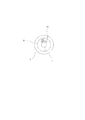
- FIG. 5 is a plan view of the protrusion and the shielding plate in FIG. 4.
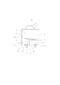
- FIG. 1 shows a portable ultrasonic mist generator according to the present invention.
- This apparatus has a liquid storage tank 1, an ultrasonic transducer 2, and a transmission film 3.
- the ultrasonic transducer 2 is provided on the bottom surface of the tank 1, and the transmission membrane 3 is provided in the tank 1.
- the lower part of the tank 1 is filled with the liquid 4, the liquid 4 is sealed by the transmission film 3, and the liquid 5 is introduced into the upper part of the tank 1.
- the ultrasonic wave 6 is oscillated by the ultrasonic vibrator 2, the ultrasonic wave 6 is transmitted by the transmission film 3, the liquids 4 and 5 in the tank 1 are vibrated by the ultrasonic wave 6, and the liquid column is ejected from the liquid surface 7.
- mist is generated by the liquid column.
- this device can be used for facial surgery, and mist can be sprayed on the face and absorbed by the skin.
- the packing 9 is provided around the ultrasonic vibrator 2, and no leakage occurs between the tank 1 and the ultrasonic vibrator 2.
- the packing 9 is annular and made of rubber.
- a shielding plate 10 is provided above the packing 9, the packing 9 is shielded by the shielding plate 10, and a number of protrusions 11 are formed on the upper surface of the shielding plate 10.
- the shielding plate 10 is also annular. As shown in FIG. 3, the protrusion 11 has a conical or cylindrical shape and has a slope 12.
- the ultrasonic vibrator 2 is fitted into the packing 9, the bottom surface of the tank 1 is formed by the heat radiating plate 13, the packing 9 is pushed up toward the heat radiating plate 13, and is pressed against the heat radiating plate 13. Yes. Therefore, no leakage occurs between the heat radiating plate 13 and the ultrasonic vibrator 2, and no leakage occurs between the tank 1 and the ultrasonic vibrator 2.
- the heat radiating plate 13 is for releasing the heat of the ultrasonic vibrator 2 and is annular.
- the shielding plate 10 is attached to the upper surface of the heat radiating plate 13. Further, as shown in FIG. 2, a large number of protrusions 11 are formed over the entire circumference of the shielding plate 10, and the protrusions 11 are in contact with or close to each other.
- the protrusion 11 and the shielding plate 10 are made of resin.
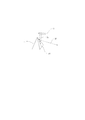
- the transmission film 3 is attached to the partition wall 14 and is arranged not to be horizontal but to be inclined at a certain angle. Therefore, when the ultrasonic wave 6 reaches the transmission film 3 and the ultrasonic wave 6 is transmitted by the transmission film 3, the ultrasonic wave 6 is reflected from the transmission film 3, but the reflected wave 15 is not vertical but travels obliquely. .
- the reflected wave 15 travels toward the packing 9.
- the packing 9 is shielded by the shielding plate 10, and a number of protrusions 11 are formed on the upper surface of the shielding plate 10 as described above. is there. Therefore, the reflected wave 15 is blocked by the protrusion 11 and the shielding plate 10, the reflected wave 15 does not reach the packing 9, and the packing 9 is not burned by heat.
- the protrusion 11 has a pyramid shape or a cone shape. Therefore, when the reflected wave 15 reaches the protrusion 11, it is reflected from the protrusion 11, but there is no problem of the secondary wave 16.
- a secondary wave 16 is induced by the inclined surface 12 of the protrusion 11, and the secondary wave 16 travels sideways, not upward. Therefore, the secondary wave 16 does not reach the partition wall 14, and the partition wall 14 is not burnt by heat.
- the direction of the secondary wave 16 can be adjusted and selected according to the angle of the protrusion 11.
- the protrusion 11 has a pyramid shape or a conical shape, and when the reflected wave 15 is received, the energy amount per unit area is small due to the slope 12. Further, as described above, the protrusion 11 and the shielding plate 10 are made of resin. Accordingly, the reflected wave 15 can be absorbed by the protrusion 11 and the shielding plate 10, and the secondary wave 16 can be reduced by the amount of absorption.
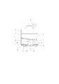
- FIG. 4 shows another embodiment.
- the shielding plate 10 is disposed above the ultrasonic transducer 2, the packing 9 is shielded by the shielding plate 10, and a large number of protrusions 11 are formed on the upper surface of the shielding plate 10.
- the packing 9 is annular and made of rubber.
- the shielding plate 10 is also annular.
- the protrusion 11 has a conical shape or a cylindrical shape. Other configurations are the same as those in FIG.
- the reflected wave 15 is blocked by the protrusion 11 and the shielding plate 10, the reflecting plate 15 does not reach the packing 9, and the packing 9 is not burned by heat. Furthermore, the secondary wave 16 is induced by the slope of the protrusion 11 and the secondary wave 16 travels sideways, not upward. Therefore, the secondary wave 16 does not reach the partition wall 14, and the partition wall 14 is not burnt by heat.
- the direction of the secondary wave 16 can be adjusted and selected according to the angle of the protrusion 11.
- the protrusion 11 has a pyramid shape or a cone shape, and when receiving the reflected wave 15, the energy amount per unit area is small. Further, the protrusion 11 and the shielding plate 10 are made of resin. Accordingly, the reflected wave 15 can be absorbed by the protrusion 11 and the shielding plate 10, and the secondary wave 16 can be reduced by the amount of absorption.
Landscapes
- Health & Medical Sciences (AREA)
- Public Health (AREA)
- Engineering & Computer Science (AREA)
- Chemical & Material Sciences (AREA)
- Physical Education & Sports Medicine (AREA)
- Dispersion Chemistry (AREA)
- Life Sciences & Earth Sciences (AREA)
- Animal Behavior & Ethology (AREA)
- General Health & Medical Sciences (AREA)
- Veterinary Medicine (AREA)
- Pain & Pain Management (AREA)
- Rehabilitation Therapy (AREA)
- Epidemiology (AREA)
- Combustion & Propulsion (AREA)
- Mechanical Engineering (AREA)
- General Engineering & Computer Science (AREA)
- Devices For Medical Bathing And Washing (AREA)
- Special Spraying Apparatus (AREA)
Abstract
L'invention porte sur un générateur de vapeur portatif à ultrasons, qui est constitué par un réservoir de stockage de liquide (1), un vibrateur ultrasonore (2), un film de transmission (3) qui transmet des ondes ultrasonores, et un rembourrage (9) disposé entre le réservoir de stockage de liquide (1) et le vibrateur ultrasonore (2). Une plaque de blocage (10) comportant de nombreuses sections saillantes pyramidales ou coniques (11) formées sur une surface supérieure de celle-ci est disposée au-dessus du rembourrage (9) ou du vibrateur ultrasonore (2). Ainsi, des ondes réfléchies (15) d'ondes ultrasonores (6) sont diffusées, absorbées et bloquées par les sections saillantes (11) et la plaque de blocage (10), et les ondes réfléchies n'atteignent pas le rembourrage (9).
Applications Claiming Priority (2)
| Application Number | Priority Date | Filing Date | Title |
|---|---|---|---|
| JP2008-267248 | 2008-10-16 | ||
| JP2008267248A JP5167064B2 (ja) | 2008-10-16 | 2008-10-16 | 携帯用超音波ミスト発生装置 |
Publications (1)
| Publication Number | Publication Date |
|---|---|
| WO2010044368A1 true WO2010044368A1 (fr) | 2010-04-22 |
Family
ID=42106532
Family Applications (1)
| Application Number | Title | Priority Date | Filing Date |
|---|---|---|---|
| PCT/JP2009/067550 WO2010044368A1 (fr) | 2008-10-16 | 2009-10-08 | Générateur de vapeur portatif à ultrasons |
Country Status (3)
| Country | Link |
|---|---|
| JP (1) | JP5167064B2 (fr) |
| TW (1) | TW201016323A (fr) |
| WO (1) | WO2010044368A1 (fr) |
Cited By (2)
| Publication number | Priority date | Publication date | Assignee | Title |
|---|---|---|---|---|
| CN102697639A (zh) * | 2011-03-28 | 2012-10-03 | 松下电器产业株式会社 | 雾发生装置 |
| CN113412162A (zh) * | 2020-01-17 | 2021-09-17 | 东芝三菱电机产业系统株式会社 | 超声波雾化装置 |
Families Citing this family (2)
| Publication number | Priority date | Publication date | Assignee | Title |
|---|---|---|---|---|
| US8925833B2 (en) * | 2010-07-26 | 2015-01-06 | Yonwoo Co., Ltd | Portable electric mist supply apparatus for liquid cosmetics |
| KR101843090B1 (ko) * | 2016-01-26 | 2018-03-28 | (주)닥터스텍 | 초음파 발진기 및 이를 포함하는 초음파 새싹재배장치 |
Citations (5)
| Publication number | Priority date | Publication date | Assignee | Title |
|---|---|---|---|---|
| JPS59209675A (ja) * | 1984-04-18 | 1984-11-28 | Matsushita Electric Ind Co Ltd | 超音波霧化装置 |
| JPS59209674A (ja) * | 1984-04-16 | 1984-11-28 | Matsushita Electric Ind Co Ltd | 超音波霧化装置 |
| JP2002326045A (ja) * | 2001-05-08 | 2002-11-12 | Koshin Kogyo:Kk | 超音波霧化装置 |
| JP2006142119A (ja) * | 2004-11-16 | 2006-06-08 | Konishi Seiko Kk | 携帯用超音波霧化装置 |
| JP2008207052A (ja) * | 2007-02-23 | 2008-09-11 | Mitsubishi Electric Corp | 超音波霧化装置及びそれを備えた設備機器 |
-
2008
- 2008-10-16 JP JP2008267248A patent/JP5167064B2/ja active Active
-
2009
- 2009-10-05 TW TW098133671A patent/TW201016323A/zh unknown
- 2009-10-08 WO PCT/JP2009/067550 patent/WO2010044368A1/fr active Application Filing
Patent Citations (5)
| Publication number | Priority date | Publication date | Assignee | Title |
|---|---|---|---|---|
| JPS59209674A (ja) * | 1984-04-16 | 1984-11-28 | Matsushita Electric Ind Co Ltd | 超音波霧化装置 |
| JPS59209675A (ja) * | 1984-04-18 | 1984-11-28 | Matsushita Electric Ind Co Ltd | 超音波霧化装置 |
| JP2002326045A (ja) * | 2001-05-08 | 2002-11-12 | Koshin Kogyo:Kk | 超音波霧化装置 |
| JP2006142119A (ja) * | 2004-11-16 | 2006-06-08 | Konishi Seiko Kk | 携帯用超音波霧化装置 |
| JP2008207052A (ja) * | 2007-02-23 | 2008-09-11 | Mitsubishi Electric Corp | 超音波霧化装置及びそれを備えた設備機器 |
Cited By (4)
| Publication number | Priority date | Publication date | Assignee | Title |
|---|---|---|---|---|
| CN102697639A (zh) * | 2011-03-28 | 2012-10-03 | 松下电器产业株式会社 | 雾发生装置 |
| CN113412162A (zh) * | 2020-01-17 | 2021-09-17 | 东芝三菱电机产业系统株式会社 | 超声波雾化装置 |
| CN113412162B (zh) * | 2020-01-17 | 2022-08-09 | 东芝三菱电机产业系统株式会社 | 超声波雾化装置 |
| EP3909689A4 (fr) * | 2020-01-17 | 2022-10-19 | Toshiba Mitsubishi-Electric Industrial Systems Corporation | Dispositif d'atomisation à ultrasons |
Also Published As
| Publication number | Publication date |
|---|---|
| TW201016323A (en) | 2010-05-01 |
| JP2010094602A (ja) | 2010-04-30 |
| JP5167064B2 (ja) | 2013-03-21 |
Similar Documents
| Publication | Publication Date | Title |
|---|---|---|
| JP4199288B1 (ja) | 携帯用超音波ミスト発生美顔術装置 | |
| WO2010044368A1 (fr) | Générateur de vapeur portatif à ultrasons | |
| US20080156320A1 (en) | Ultrasonic nebulizer and method for atomizing liquid | |
| EP3838420A1 (fr) | Dispositif d'atomisation réducteur de bruit qui s'adapte au niveau d'eau | |
| JP6932237B2 (ja) | 霧化装置および調湿装置 | |
| JP2017144428A (ja) | 超音波霧化装置 | |
| JP3751523B2 (ja) | 液滴吐出装置 | |
| JP2009028582A (ja) | 超音波霧発生装置 | |
| JP2009039618A (ja) | 携帯用超音波ミスト発生装置 | |
| JP2016185506A (ja) | 超音波霧化装置 | |
| JP2010094602A5 (fr) | ||
| US8529508B2 (en) | Fluid ejection device and medical device | |
| WO2021144952A1 (fr) | Dispositif d'atomisation à ultrasons | |
| JP4812657B2 (ja) | 超音波霧化装置及びそれを備えた設備機器 | |
| WO2010041309A1 (fr) | Générateur de brouillard ultrasonique portable | |
| JP2011156458A (ja) | ミスト生成器 | |
| US20150076245A1 (en) | Device for nebulizing a liquid | |
| WO2023204190A1 (fr) | Dispositif d'atomisation à ultrasons | |
| JP2008207055A (ja) | 超音波霧化装置及びそれを備えた設備機器 | |
| JP2024064983A (ja) | 超音波発生装置 | |
| JPH0924351A (ja) | 超音波洗浄装置 | |
| JPS599139Y2 (ja) | 超音波燃料霧化装置 | |
| JP2008155170A (ja) | 超音波霧化器 | |
| JP2989707B2 (ja) | 超音波洗浄装置 | |
| JP2012200534A (ja) | ミスト発生装置 |
Legal Events
| Date | Code | Title | Description |
|---|---|---|---|
| 121 | Ep: the epo has been informed by wipo that ep was designated in this application |
Ref document number: 09820546 Country of ref document: EP Kind code of ref document: A1 |
|
| DPE1 | Request for preliminary examination filed after expiration of 19th month from priority date (pct application filed from 20040101) | ||
| NENP | Non-entry into the national phase |
Ref country code: DE |
|
| 122 | Ep: pct application non-entry in european phase |
Ref document number: 09820546 Country of ref document: EP Kind code of ref document: A1 |