WO2010044368A1 - 携帯用超音波ミスト発生装置 - Google Patents
携帯用超音波ミスト発生装置 Download PDFInfo
- Publication number
- WO2010044368A1 WO2010044368A1 PCT/JP2009/067550 JP2009067550W WO2010044368A1 WO 2010044368 A1 WO2010044368 A1 WO 2010044368A1 JP 2009067550 W JP2009067550 W JP 2009067550W WO 2010044368 A1 WO2010044368 A1 WO 2010044368A1
- Authority
- WO
- WIPO (PCT)
- Prior art keywords
- ultrasonic
- packing
- tank
- shielding plate
- liquid
- Prior art date
Links
Images
Classifications
-
- F—MECHANICAL ENGINEERING; LIGHTING; HEATING; WEAPONS; BLASTING
- F24—HEATING; RANGES; VENTILATING
- F24F—AIR-CONDITIONING; AIR-HUMIDIFICATION; VENTILATION; USE OF AIR CURRENTS FOR SCREENING
- F24F6/00—Air-humidification, e.g. cooling by humidification
- F24F6/12—Air-humidification, e.g. cooling by humidification by forming water dispersions in the air
-
- A—HUMAN NECESSITIES
- A61—MEDICAL OR VETERINARY SCIENCE; HYGIENE
- A61H—PHYSICAL THERAPY APPARATUS, e.g. DEVICES FOR LOCATING OR STIMULATING REFLEX POINTS IN THE BODY; ARTIFICIAL RESPIRATION; MASSAGE; BATHING DEVICES FOR SPECIAL THERAPEUTIC OR HYGIENIC PURPOSES OR SPECIFIC PARTS OF THE BODY
- A61H33/00—Bathing devices for special therapeutic or hygienic purposes
- A61H33/06—Artificial hot-air or cold-air baths; Steam or gas baths or douches, e.g. sauna or Finnish baths
- A61H33/12—Steam baths for the face
-
- B—PERFORMING OPERATIONS; TRANSPORTING
- B05—SPRAYING OR ATOMISING IN GENERAL; APPLYING FLUENT MATERIALS TO SURFACES, IN GENERAL
- B05B—SPRAYING APPARATUS; ATOMISING APPARATUS; NOZZLES
- B05B17/00—Apparatus for spraying or atomising liquids or other fluent materials, not covered by the preceding groups
- B05B17/04—Apparatus for spraying or atomising liquids or other fluent materials, not covered by the preceding groups operating with special methods
- B05B17/06—Apparatus for spraying or atomising liquids or other fluent materials, not covered by the preceding groups operating with special methods using ultrasonic or other kinds of vibrations
- B05B17/0607—Apparatus for spraying or atomising liquids or other fluent materials, not covered by the preceding groups operating with special methods using ultrasonic or other kinds of vibrations generated by electrical means, e.g. piezoelectric transducers
- B05B17/0615—Apparatus for spraying or atomising liquids or other fluent materials, not covered by the preceding groups operating with special methods using ultrasonic or other kinds of vibrations generated by electrical means, e.g. piezoelectric transducers spray being produced at the free surface of the liquid or other fluent material in a container and subjected to the vibrations
-
- F—MECHANICAL ENGINEERING; LIGHTING; HEATING; WEAPONS; BLASTING
- F24—HEATING; RANGES; VENTILATING
- F24F—AIR-CONDITIONING; AIR-HUMIDIFICATION; VENTILATION; USE OF AIR CURRENTS FOR SCREENING
- F24F2221/00—Details or features not otherwise provided for
- F24F2221/12—Details or features not otherwise provided for transportable
-
- Y—GENERAL TAGGING OF NEW TECHNOLOGICAL DEVELOPMENTS; GENERAL TAGGING OF CROSS-SECTIONAL TECHNOLOGIES SPANNING OVER SEVERAL SECTIONS OF THE IPC; TECHNICAL SUBJECTS COVERED BY FORMER USPC CROSS-REFERENCE ART COLLECTIONS [XRACs] AND DIGESTS
- Y02—TECHNOLOGIES OR APPLICATIONS FOR MITIGATION OR ADAPTATION AGAINST CLIMATE CHANGE
- Y02B—CLIMATE CHANGE MITIGATION TECHNOLOGIES RELATED TO BUILDINGS, e.g. HOUSING, HOUSE APPLIANCES OR RELATED END-USER APPLICATIONS
- Y02B30/00—Energy efficient heating, ventilation or air conditioning [HVAC]
- Y02B30/70—Efficient control or regulation technologies, e.g. for control of refrigerant flow, motor or heating
Definitions
- This invention relates to a portable ultrasonic mist generator.
- Patent Document 1 Japanese Patent Application Laid-Open No. 2005-111328
- Patent Document 2 Japanese Patent Application Laid-Open No. 2006-142119
- the apparatus of each publication has a liquid storage tank, an ultrasonic transducer, and a transmission film.
- the ultrasonic transducer is provided on the bottom surface of the tank, and the transmission membrane is provided in the tank. Accordingly, ultrasonic waves are oscillated by the ultrasonic vibrator, ultrasonic waves are transmitted by the transmission film, the liquid in the tank is vibrated by the ultrasonic waves, the liquid column is ejected from the liquid surface, and mist is generated by the liquid column. Further, the nozzle is connected to the tank, air is sent to the tank, mist is sent by the air, and this is ejected from the nozzle.
- this device can be used for facial surgery, and mist can be sprayed on the face and absorbed by the skin.
- a packing is provided around the ultrasonic vibrator.
- the packing is annular and made of rubber.
- the ultrasonic wave reaches the transmission film and the ultrasonic wave is transmitted by the transmission film, the ultrasonic wave is reflected from the transmission film, and the reflected wave does not reach the packing. For this reason, there has been a problem that the reflected wave is absorbed by the packing and converted into heat, which causes the packing to burn.
- the present invention has been made for the purpose of eliminating the problems associated with the reflected waves of the ultrasonic waves in the portable ultrasonic mist generator.
- the liquid storage tank is combined with the ultrasonic vibrator and the transmission film, the ultrasonic vibrator is provided on the bottom surface of the tank, and the transmission film is provided in the tank. Accordingly, ultrasonic waves are oscillated by the ultrasonic vibrator, ultrasonic waves are transmitted by the transmission film, the liquid in the tank is vibrated by the ultrasonic waves, the liquid column is ejected from the liquid surface, and mist is generated by the liquid column. Further, a packing is provided around the ultrasonic transducer, and no leakage occurs between the tank and the ultrasonic transducer.
- a shielding plate is provided above the packing or the ultrasonic transducer, the packing is shielded by the shielding plate, and a large number of protrusions are formed on the upper surface of the shielding plate.
- the protrusion has a pyramid shape or a cone shape.
- FIG. 5 is a plan view of the protrusion and the shielding plate in FIG. 4.
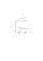
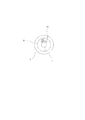
- FIG. 1 shows a portable ultrasonic mist generator according to the present invention.
- This apparatus has a liquid storage tank 1, an ultrasonic transducer 2, and a transmission film 3.
- the ultrasonic transducer 2 is provided on the bottom surface of the tank 1, and the transmission membrane 3 is provided in the tank 1.
- the lower part of the tank 1 is filled with the liquid 4, the liquid 4 is sealed by the transmission film 3, and the liquid 5 is introduced into the upper part of the tank 1.
- the ultrasonic wave 6 is oscillated by the ultrasonic vibrator 2, the ultrasonic wave 6 is transmitted by the transmission film 3, the liquids 4 and 5 in the tank 1 are vibrated by the ultrasonic wave 6, and the liquid column is ejected from the liquid surface 7.
- mist is generated by the liquid column.
- this device can be used for facial surgery, and mist can be sprayed on the face and absorbed by the skin.
- the packing 9 is provided around the ultrasonic vibrator 2, and no leakage occurs between the tank 1 and the ultrasonic vibrator 2.
- the packing 9 is annular and made of rubber.
- a shielding plate 10 is provided above the packing 9, the packing 9 is shielded by the shielding plate 10, and a number of protrusions 11 are formed on the upper surface of the shielding plate 10.
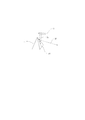
- the shielding plate 10 is also annular. As shown in FIG. 3, the protrusion 11 has a conical or cylindrical shape and has a slope 12.
- the ultrasonic vibrator 2 is fitted into the packing 9, the bottom surface of the tank 1 is formed by the heat radiating plate 13, the packing 9 is pushed up toward the heat radiating plate 13, and is pressed against the heat radiating plate 13. Yes. Therefore, no leakage occurs between the heat radiating plate 13 and the ultrasonic vibrator 2, and no leakage occurs between the tank 1 and the ultrasonic vibrator 2.
- the heat radiating plate 13 is for releasing the heat of the ultrasonic vibrator 2 and is annular.
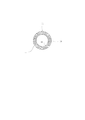
- the shielding plate 10 is attached to the upper surface of the heat radiating plate 13. Further, as shown in FIG. 2, a large number of protrusions 11 are formed over the entire circumference of the shielding plate 10, and the protrusions 11 are in contact with or close to each other.
- the protrusion 11 and the shielding plate 10 are made of resin.
- the transmission film 3 is attached to the partition wall 14 and is arranged not to be horizontal but to be inclined at a certain angle. Therefore, when the ultrasonic wave 6 reaches the transmission film 3 and the ultrasonic wave 6 is transmitted by the transmission film 3, the ultrasonic wave 6 is reflected from the transmission film 3, but the reflected wave 15 is not vertical but travels obliquely. .
- the reflected wave 15 travels toward the packing 9.
- the packing 9 is shielded by the shielding plate 10, and a number of protrusions 11 are formed on the upper surface of the shielding plate 10 as described above. is there. Therefore, the reflected wave 15 is blocked by the protrusion 11 and the shielding plate 10, the reflected wave 15 does not reach the packing 9, and the packing 9 is not burned by heat.
- the protrusion 11 has a pyramid shape or a cone shape. Therefore, when the reflected wave 15 reaches the protrusion 11, it is reflected from the protrusion 11, but there is no problem of the secondary wave 16.
- a secondary wave 16 is induced by the inclined surface 12 of the protrusion 11, and the secondary wave 16 travels sideways, not upward. Therefore, the secondary wave 16 does not reach the partition wall 14, and the partition wall 14 is not burnt by heat.
- the direction of the secondary wave 16 can be adjusted and selected according to the angle of the protrusion 11.
- the protrusion 11 has a pyramid shape or a conical shape, and when the reflected wave 15 is received, the energy amount per unit area is small due to the slope 12. Further, as described above, the protrusion 11 and the shielding plate 10 are made of resin. Accordingly, the reflected wave 15 can be absorbed by the protrusion 11 and the shielding plate 10, and the secondary wave 16 can be reduced by the amount of absorption.
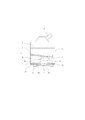
- FIG. 4 shows another embodiment.
- the shielding plate 10 is disposed above the ultrasonic transducer 2, the packing 9 is shielded by the shielding plate 10, and a large number of protrusions 11 are formed on the upper surface of the shielding plate 10.
- the packing 9 is annular and made of rubber.
- the shielding plate 10 is also annular.
- the protrusion 11 has a conical shape or a cylindrical shape. Other configurations are the same as those in FIG.
- the reflected wave 15 is blocked by the protrusion 11 and the shielding plate 10, the reflecting plate 15 does not reach the packing 9, and the packing 9 is not burned by heat. Furthermore, the secondary wave 16 is induced by the slope of the protrusion 11 and the secondary wave 16 travels sideways, not upward. Therefore, the secondary wave 16 does not reach the partition wall 14, and the partition wall 14 is not burnt by heat.
- the direction of the secondary wave 16 can be adjusted and selected according to the angle of the protrusion 11.
- the protrusion 11 has a pyramid shape or a cone shape, and when receiving the reflected wave 15, the energy amount per unit area is small. Further, the protrusion 11 and the shielding plate 10 are made of resin. Accordingly, the reflected wave 15 can be absorbed by the protrusion 11 and the shielding plate 10, and the secondary wave 16 can be reduced by the amount of absorption.
Abstract
液体収容タンク(1)と、超音波振動子(2)と、超音波を伝達する伝達膜(3)と、液体収容タンク(1)と超音波振動子(2)との間に設けられたパッキン(9)とからなる携帯用超音波ミスト発生装置において、角錐状または円錐状をなす突起(11)が上面に多数形成された遮蔽板(10)を、パッキン(9)または超音波振動子(2)の上方に配置するものである。当該構成により、超音波(6)の反射波(15)が、突起(11)および遮蔽板(10)で拡散・吸収・遮断され、パッキン(9)に達することがない。
Description
この発明は、携帯用超音波ミスト発生装置に関するものである。
本願出願前、出願人は新しい形式の携帯用超音波ミスト発生装置を開発し、提案した。特開2005-111328号公報(特許文献1)および特開2006-142119号公報(特許文献2)に記載されているものがそれである。
各公報の装置は液体収容タンク、超音波振動子および伝達膜を有し、超音波振動子はタンクの底面に設けられ、伝達膜はタンク内に設けられる。したがって、超音波振動子によって超音波が発振され、伝達膜によって超音波が伝達され、超音波によってタンクの液体が振動し、その液面から液柱が噴出し、液柱によってミストが発生する。さらに、ノズルがタンクに接続され、エアがタンクに送られ、エアによってミストが送られ、これがノズルから噴出する。したがって、たとえば、この装置を美顔術に使用し、ミストを顔に吹き付け、皮膚に吸収させることができる。
この場合、タンクと超音波振動子間に漏れが生じないようにする必要があり、通常、パッキンが超音波振動子のまわりに設けられる。パッキンは環状のもので、ゴム製である。しかしながら、超音波が伝達膜に達し、伝達膜によって超音波が伝達されるとき、超音波が伝達膜から反射し、反射波がパッキンに達することはさけられない。このため、反射波がパッキンに吸収され、熱に変換され、熱によってパッキンが焦げてしまうという問題があった。
したがって、この発明は、携帯用超音波ミスト発生装置において、超音波の反射波にともなう問題がないようにすることを目的としてなされたものである。
この発明によれば、液体収容タンクが超音波振動子および伝達膜と組み合わされ、超音波振動子はタンクの底面に設けられ、伝達膜はタンク内に設けられる。したがって、超音波振動子によって超音波が発振され、伝達膜によって超音波が伝達され、超音波によってタンクの液体が振動し、その液面から液柱が噴出し、液柱によってミストが発生する。さらに、パッキンが超音波振動子のまわりに設けられ、タンクと超音波振動子間に洩れは生じない。さらに、遮蔽板がパッキンまたは超音波振動子の上方に設けられ、遮蔽板によってパッキンが遮蔽され、多数の突起が遮蔽板の上面に形成される。突起は角錐状または円錐状をなす。
以下、この発明の実施例を説明する。
図1はこの発明にかかる携帯用超音波ミスト発生装置を示す。この装置は液体収容タンク1、超音波振動子2および伝達膜3を有し、超音波振動子2はタンク1の底面に設けられ、伝達膜3はタンク1内に設けられている。そして、タンク1の下部に液体4が充填され、伝達膜3によって液体4が封入され、タンク1の上部に液体5が導入される。したがって、超音波振動子2によって超音波6が発振され、伝達膜3によって超音波6が伝達され、超音波6によってタンク1の液体4,5が振動し、その液面7から液柱が噴出し、液柱によってミストが発生する。さらに、ノズル8がタンク1に接続され、エアがタンク1に送られ、エアによってミストが送られ、これがノズル8から噴出する。したがって、たとえば、この装置を美顔術に使用し、ミストを顔に吹き付け、皮膚に吸収させることができる。
さらに、この装置では、パッキン9が超音波振動子2のまわりに設けられており、タンク1と超音波振動子2間に洩れは生じない。パッキン9は環状のもので、ゴム製である。さらに、遮蔽板10がパッキン9の上方に設けられ、遮蔽板10によってパッキン9が遮蔽されており、多数の突起11が遮蔽板10の上面に形成されている。遮蔽板10も環状のものである。図3に示すように、突起11は円錐状または円筒状をなし、斜面12を有する。
さらに、この実施例では、超音波振動子2がパッキン9にはめ込まれ、放熱板13によってタンク1の底面が形成され、パッキン9が放熱板13に向かって押し上げられ、放熱板13に押し付けられている。したがって、放熱板13と超音波振動子2間に洩れが生じず、タンク1と超音波振動子2間に洩れは生じない。放熱板13は超音波振動子2の熱を放出するためのもので、環状である。そして、遮蔽板10が放熱板13の上面に取り付けられている。さらに、図2に示すように、多数の突起11が遮蔽板10の全周にわたって形成され、各突起11が互いに接触または近接している。突起11および遮蔽板10は樹脂製である。
一方、伝達膜3は隔壁14に取り付けられ、水平ではなく、一定角度傾斜するよう配置されている。したがって、超音波6が伝達膜3に達し、伝達膜3によって超音波6が伝達されるとき、超音波6が伝達膜3から反射するが、その反射波15は垂直ではなく、斜めに進行する。
さらに、反射波15がパッキン9に向かって進行するが、この装置では、遮蔽板10によってパッキン9が遮蔽され、多数の突起11が遮蔽板10の上面に形成されていることは前述したとおりである。したがって、突起11および遮蔽板10によって反射波15が遮断され、反射波15がパッキン9に達することはなく、熱によってパッキン9が焦げることはない。
さらに、突起11は角錐状または円錐状であることは前述したとおりである。したがって、反射波15が突起11に達したとき、それが突起11から反射するが、その二次波16の問題もない。突起11の斜面12によって二次波16が誘導され、二次波16は上向きではなく、横向きに進行する。したがって、二次波16が隔壁14に達することはなく、熱によって隔壁14が焦げることもない。突起11の角度によって二次波16の方向を調整し、選定することもできる。
突起11は角錐状または円錐状であり、斜面12をもつ関係上、反射波15を受けるとき、その単位面積あたりのエネルギー量は小さい。さらに、突起11および遮蔽板10は樹脂製であることは前述したとおりである。したがって、突起11および遮蔽板10に反射波15を吸収させ、その吸収量だけ二次波16を減少させることもできる。
図4は他の実施例を示す。この実施例では、遮蔽板10が超音波振動子2の上方に配置され、遮蔽板10によってパッキン9が遮蔽されており、多数の突起11が遮蔽板10の上面に形成されている。パッキン9は環状のもので、ゴム製である。遮蔽板10も環状のものである。突起11は円錐状または円筒状をなす。その他の構成は図1のものと同様である。
したがって、図1のものと同様、突起11および遮蔽板10によって反射波15が遮断され、反射板15がパッキン9に達することはなく、熱によってパッキン9が焦げることはない。さらに、突起11の斜面によって二次波16が誘導され、二次波16は上向きではなく、横向きに進行する。したがって、二次波16が隔壁14に達することはなく、熱によって隔壁14が焦げることもない。突起11の角度によって二次波16の方向を調整し、選定することもできる。
突起11は角錐状または円錐状であり、反射波15を受けるとき、その単位面積あたりのエネルギー量は小さい。さらに、突起11および遮蔽板10は樹脂製である。したがって、突起11および遮蔽板10に反射波15を吸収させ、その吸収量だけ二次波16を減少させることもできる。
1 タンク
2 超音波振動子
3 伝達膜
4,5 液体
6 超音波
9 パッキン
10 遮蔽版
11 突起
15 反射波
2 超音波振動子
3 伝達膜
4,5 液体
6 超音波
9 パッキン
10 遮蔽版
11 突起
15 反射波
Claims (1)
- 液体収容タンクと、
前記タンクの底面に設けられ、超音波を発振させ、前記超音波によって前記タンクの液体を振動させ、その液面から液柱を噴出させ、前記液柱によってミストを発生させる超音波振動子と、
前記タンク内に設けられ、前記超音波を伝達する伝達膜と、
前記超音波振動子のまわりに設けられ、前記タンクと前記超音波振動子間に洩れが生じないようにするパッキンと、
前記パッキンまたは前記超音波振動子の上方に配置され、前記パッキンを遮蔽する遮蔽板と、
角錐状または円錐状をなし、前記遮蔽板の上面に形成された多数の突起とからなる携帯用超音波ミスト発生装置。
Applications Claiming Priority (2)
| Application Number | Priority Date | Filing Date | Title |
|---|---|---|---|
| JP2008267248A JP5167064B2 (ja) | 2008-10-16 | 2008-10-16 | 携帯用超音波ミスト発生装置 |
| JP2008-267248 | 2008-10-16 |
Publications (1)
| Publication Number | Publication Date |
|---|---|
| WO2010044368A1 true WO2010044368A1 (ja) | 2010-04-22 |
Family
ID=42106532
Family Applications (1)
| Application Number | Title | Priority Date | Filing Date |
|---|---|---|---|
| PCT/JP2009/067550 WO2010044368A1 (ja) | 2008-10-16 | 2009-10-08 | 携帯用超音波ミスト発生装置 |
Country Status (3)
| Country | Link |
|---|---|
| JP (1) | JP5167064B2 (ja) |
| TW (1) | TW201016323A (ja) |
| WO (1) | WO2010044368A1 (ja) |
Cited By (2)
| Publication number | Priority date | Publication date | Assignee | Title |
|---|---|---|---|---|
| CN102697639A (zh) * | 2011-03-28 | 2012-10-03 | 松下电器产业株式会社 | 雾发生装置 |
| CN113412162A (zh) * | 2020-01-17 | 2021-09-17 | 东芝三菱电机产业系统株式会社 | 超声波雾化装置 |
Families Citing this family (2)
| Publication number | Priority date | Publication date | Assignee | Title |
|---|---|---|---|---|
| EP2462833A4 (en) * | 2010-07-26 | 2013-06-12 | Yonwoo Co Ltd | PORTABLE DISTRIBUTOR OF LIQUID COSMETIC PRODUCT MIST WORKING ELECTRICALLY |
| KR101843090B1 (ko) * | 2016-01-26 | 2018-03-28 | (주)닥터스텍 | 초음파 발진기 및 이를 포함하는 초음파 새싹재배장치 |
Citations (5)
| Publication number | Priority date | Publication date | Assignee | Title |
|---|---|---|---|---|
| JPS59209674A (ja) * | 1984-04-16 | 1984-11-28 | Matsushita Electric Ind Co Ltd | 超音波霧化装置 |
| JPS59209675A (ja) * | 1984-04-18 | 1984-11-28 | Matsushita Electric Ind Co Ltd | 超音波霧化装置 |
| JP2002326045A (ja) * | 2001-05-08 | 2002-11-12 | Koshin Kogyo:Kk | 超音波霧化装置 |
| JP2006142119A (ja) * | 2004-11-16 | 2006-06-08 | Konishi Seiko Kk | 携帯用超音波霧化装置 |
| JP2008207052A (ja) * | 2007-02-23 | 2008-09-11 | Mitsubishi Electric Corp | 超音波霧化装置及びそれを備えた設備機器 |
-
2008
- 2008-10-16 JP JP2008267248A patent/JP5167064B2/ja active Active
-
2009
- 2009-10-05 TW TW098133671A patent/TW201016323A/zh unknown
- 2009-10-08 WO PCT/JP2009/067550 patent/WO2010044368A1/ja active Application Filing
Patent Citations (5)
| Publication number | Priority date | Publication date | Assignee | Title |
|---|---|---|---|---|
| JPS59209674A (ja) * | 1984-04-16 | 1984-11-28 | Matsushita Electric Ind Co Ltd | 超音波霧化装置 |
| JPS59209675A (ja) * | 1984-04-18 | 1984-11-28 | Matsushita Electric Ind Co Ltd | 超音波霧化装置 |
| JP2002326045A (ja) * | 2001-05-08 | 2002-11-12 | Koshin Kogyo:Kk | 超音波霧化装置 |
| JP2006142119A (ja) * | 2004-11-16 | 2006-06-08 | Konishi Seiko Kk | 携帯用超音波霧化装置 |
| JP2008207052A (ja) * | 2007-02-23 | 2008-09-11 | Mitsubishi Electric Corp | 超音波霧化装置及びそれを備えた設備機器 |
Cited By (4)
| Publication number | Priority date | Publication date | Assignee | Title |
|---|---|---|---|---|
| CN102697639A (zh) * | 2011-03-28 | 2012-10-03 | 松下电器产业株式会社 | 雾发生装置 |
| CN113412162A (zh) * | 2020-01-17 | 2021-09-17 | 东芝三菱电机产业系统株式会社 | 超声波雾化装置 |
| CN113412162B (zh) * | 2020-01-17 | 2022-08-09 | 东芝三菱电机产业系统株式会社 | 超声波雾化装置 |
| EP3909689A4 (en) * | 2020-01-17 | 2022-10-19 | Toshiba Mitsubishi-Electric Industrial Systems Corporation | ULTRASONIC ATOMIZER |
Also Published As
| Publication number | Publication date |
|---|---|
| JP5167064B2 (ja) | 2013-03-21 |
| JP2010094602A (ja) | 2010-04-30 |
| TW201016323A (en) | 2010-05-01 |
Similar Documents
| Publication | Publication Date | Title |
|---|---|---|
| JP4199288B1 (ja) | 携帯用超音波ミスト発生美顔術装置 | |
| WO2010044368A1 (ja) | 携帯用超音波ミスト発生装置 | |
| US5836515A (en) | High efficiency spraying device, in particular for spraying water in the form of micro-droplets | |
| US20080156320A1 (en) | Ultrasonic nebulizer and method for atomizing liquid | |
| JP6932237B2 (ja) | 霧化装置および調湿装置 | |
| JP3751523B2 (ja) | 液滴吐出装置 | |
| JP4990707B2 (ja) | 超音波霧発生装置 | |
| JP2010094602A5 (ja) | ||
| CN110394269A (zh) | 聚焦超声雾化装置 | |
| US20210187538A1 (en) | Adaptive water level noise reducing atomizing device | |
| US20140012302A1 (en) | Fluid ejection device and medical device | |
| WO2021144952A1 (ja) | 超音波霧化装置 | |
| JP4447656B1 (ja) | 携帯用超音波ミスト発生装置 | |
| JP4812657B2 (ja) | 超音波霧化装置及びそれを備えた設備機器 | |
| JP2011156458A (ja) | ミスト生成器 | |
| JP3123820U (ja) | 液体吐出装置 | |
| WO2023204190A1 (ja) | 超音波霧化装置 | |
| WO2006134592A3 (en) | Wave generating device with inner reflector | |
| JP2009262012A (ja) | 超音波噴霧装置 | |
| CZ339392A3 (cs) | Zařízení s koncentrací akustické energie | |
| KR101134912B1 (ko) | 피에조 방식 및 공압 방식을 혼용하는 초음파 발생 장치 및 이를 구비한 기화식 분사 장치 | |
| JP2024064983A (ja) | 超音波発生装置 | |
| JP2008155170A (ja) | 超音波霧化器 | |
| JP2989707B2 (ja) | 超音波洗浄装置 | |
| JP2012200534A (ja) | ミスト発生装置 |
Legal Events
| Date | Code | Title | Description |
|---|---|---|---|
| 121 | Ep: the epo has been informed by wipo that ep was designated in this application |
Ref document number: 09820546 Country of ref document: EP Kind code of ref document: A1 |
|
| DPE1 | Request for preliminary examination filed after expiration of 19th month from priority date (pct application filed from 20040101) | ||
| NENP | Non-entry into the national phase |
Ref country code: DE |
|
| 122 | Ep: pct application non-entry in european phase |
Ref document number: 09820546 Country of ref document: EP Kind code of ref document: A1 |