WO2010041335A1 - 車両用表示装置および表示方法 - Google Patents
車両用表示装置および表示方法 Download PDFInfo
- Publication number
- WO2010041335A1 WO2010041335A1 PCT/JP2008/068479 JP2008068479W WO2010041335A1 WO 2010041335 A1 WO2010041335 A1 WO 2010041335A1 JP 2008068479 W JP2008068479 W JP 2008068479W WO 2010041335 A1 WO2010041335 A1 WO 2010041335A1
- Authority
- WO
- WIPO (PCT)
- Prior art keywords
- display
- image
- vehicle
- unit
- display device
- Prior art date
- Legal status (The legal status is an assumption and is not a legal conclusion. Google has not performed a legal analysis and makes no representation as to the accuracy of the status listed.)
- Ceased
Links
Images



Classifications
-
- B—PERFORMING OPERATIONS; TRANSPORTING
- B60—VEHICLES IN GENERAL
- B60R—VEHICLES, VEHICLE FITTINGS, OR VEHICLE PARTS, NOT OTHERWISE PROVIDED FOR
- B60R1/00—Optical viewing arrangements; Real-time viewing arrangements for drivers or passengers using optical image capturing systems, e.g. cameras or video systems specially adapted for use in or on vehicles
- B60R1/20—Real-time viewing arrangements for drivers or passengers using optical image capturing systems, e.g. cameras or video systems specially adapted for use in or on vehicles
- B60R1/22—Real-time viewing arrangements for drivers or passengers using optical image capturing systems, e.g. cameras or video systems specially adapted for use in or on vehicles for viewing an area outside the vehicle, e.g. the exterior of the vehicle
- B60R1/23—Real-time viewing arrangements for drivers or passengers using optical image capturing systems, e.g. cameras or video systems specially adapted for use in or on vehicles for viewing an area outside the vehicle, e.g. the exterior of the vehicle with a predetermined field of view
- B60R1/26—Real-time viewing arrangements for drivers or passengers using optical image capturing systems, e.g. cameras or video systems specially adapted for use in or on vehicles for viewing an area outside the vehicle, e.g. the exterior of the vehicle with a predetermined field of view to the rear of the vehicle
-
- B—PERFORMING OPERATIONS; TRANSPORTING
- B60—VEHICLES IN GENERAL
- B60R—VEHICLES, VEHICLE FITTINGS, OR VEHICLE PARTS, NOT OTHERWISE PROVIDED FOR
- B60R11/00—Arrangements for holding or mounting articles, not otherwise provided for
- B60R11/02—Arrangements for holding or mounting articles, not otherwise provided for for radio sets, television sets, telephones, or the like; Arrangement of controls thereof
- B60R11/0229—Arrangements for holding or mounting articles, not otherwise provided for for radio sets, television sets, telephones, or the like; Arrangement of controls thereof for displays, e.g. cathodic tubes
- B60R11/0235—Arrangements for holding or mounting articles, not otherwise provided for for radio sets, television sets, telephones, or the like; Arrangement of controls thereof for displays, e.g. cathodic tubes of flat type, e.g. LCD
-
- B—PERFORMING OPERATIONS; TRANSPORTING
- B60—VEHICLES IN GENERAL
- B60R—VEHICLES, VEHICLE FITTINGS, OR VEHICLE PARTS, NOT OTHERWISE PROVIDED FOR
- B60R11/00—Arrangements for holding or mounting articles, not otherwise provided for
- B60R2011/0001—Arrangements for holding or mounting articles, not otherwise provided for characterised by position
- B60R2011/0003—Arrangements for holding or mounting articles, not otherwise provided for characterised by position inside the vehicle
- B60R2011/0005—Dashboard
-
- B—PERFORMING OPERATIONS; TRANSPORTING
- B60—VEHICLES IN GENERAL
- B60R—VEHICLES, VEHICLE FITTINGS, OR VEHICLE PARTS, NOT OTHERWISE PROVIDED FOR
- B60R2300/00—Details of viewing arrangements using cameras and displays, specially adapted for use in a vehicle
- B60R2300/80—Details of viewing arrangements using cameras and displays, specially adapted for use in a vehicle characterised by the intended use of the viewing arrangement
- B60R2300/8006—Details of viewing arrangements using cameras and displays, specially adapted for use in a vehicle characterised by the intended use of the viewing arrangement for monitoring and displaying scenes of vehicle interior, e.g. for monitoring passengers or cargo
Definitions
- the present invention relates to a display device for a vehicle and a display method for displaying an image such as navigation information or television broadcast installed in a vehicle cabin.
- display devices such as navigation devices and television receivers
- display images are installed mainly on dashboards and in dashboards where they are easily visible. There are many cases.
- one end of the joint bracket is fixed to the inner side of the casing of the in-vehicle audio apparatus main body, and the video monitor support bracket is fixed to the joint bracket so that the dashboard is secured.
- an object of the present invention is to provide a display device for a vehicle and a display method that do not impair the functions of the genuine monitor even if it is installed so as to conceal the genuine monitor.
- the vehicle display device includes a housing having a display unit for displaying an image provided on a front surface, and the housing is previously installed in a vehicle interior of the vehicle.
- a display device for a vehicle that is attached so as to at least partly overlap with another display device that is provided, a photographing unit that is provided on the back surface of the housing and that captures an image displayed on the other display device;
- display control means for controlling information based on the photographed image photographed by the photographing means to be displayed on the display unit.
- the display method wherein an image is displayed on a display unit provided on a front surface of a housing attached to a vehicle interior of a vehicle, and an imaging unit is provided on a rear surface of the housing, and the housing Is attached so as to at least partially overlap a display device installed in advance in the vehicle interior, the image displayed on the display device is taken by the photographing means, and information based on the taken photographed image is It is characterized by being displayed on the display unit.
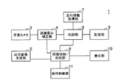
- FIG. (A), (b) is a perspective view of the display apparatus for vehicles concerning one Example of this invention. It is a block diagram of the display apparatus for vehicles shown by FIG. It is the side view which showed the attachment to the dashboard of the display apparatus for vehicles shown by FIG. (A), (b) is explanatory drawing which showed the image display in the state which attached the display apparatus for vehicles shown by FIG. It is explanatory drawing which showed the other Example of the attachment member.
- a display device for a vehicle according to an embodiment of the present invention is a display in which a casing provided with a photographing unit on the back is attached so as to overlap at least partly with another display device installed in advance in a vehicle interior.
- the control means causes the photographing means to photograph the image displayed on the other display device, and displays information based on the photographed photographed image on the display unit, so that the content displayed on the other display device is displayed. Can be displayed on the screen, and the functions of other display devices installed in advance are not impaired.
- the other display devices installed in advance are often provided at a position excellent in operability and visibility, the operability and visibility of the additionally mounted vehicle display device can also be improved. .
- the vehicle driving state acquisition means for acquiring the driving state of the vehicle may be provided, and the display control means may display information based on the photographed image on the display unit based on the driving state of the vehicle acquired by the vehicle driving state acquisition means. Good. In this way, depending on the driving condition, there are few changes in the display section such as during driving on the highway on the navigation screen, or images taken by the rear camera after the vehicle has moved backward are installed in advance. When the image is displayed on the display device, it can be photographed by the photographing means and displayed on the display unit.
- the display control means detects a change in the image displayed on the display device, information based on the photographed image may be displayed on the display unit. In this way, when the driver operates an air conditioner or the like, or when the vehicle automatically changes the display, the contents can be displayed on the display unit.
- a storage unit that stores an image pattern displayed on the display device
- the display control unit displays information based on the captured image on the display unit when the captured image matches the image pattern stored in the storage unit. You may let them. By doing so, it is possible to store an image pattern desired to be displayed on the display unit, such as an air conditioner or audio operation screen or a fuel consumption meter, so that only the display screen required by the driver can be displayed on the display unit. it can.
- the display control means may display the photographed image on the display unit as information based on the photographed image.
- photography means can be displayed on a display part as it is.
- a character recognition unit that recognizes characters and numbers included in the photographed image
- the display control unit converts the characters and numbers recognized by the character recognition unit into text information, and the text information is obtained as information based on the photographed image. May be displayed on the display unit. In this way, it is possible to make it easier to visually recognize letters and numbers than to display the captured image as it is.
- the display method according to the embodiment of the present invention is such that the housing provided with the photographing unit on the rear surface of the housing is attached by the attachment portion so that at least part of the housing overlaps with the display device installed in the vehicle interior in advance. Since the photographing unit photographs the image displayed on the display device and displays information based on the photographed captured image on the display unit, the content displayed on the other display device is displayed on the display unit. Therefore, the function of the display device installed in advance is not impaired. In addition, since the display device installed in advance is often provided at a position excellent in operability and visibility, the operability and visibility of the vehicle display device to be additionally attached can be improved.
- FIG. 1 is a perspective view of a vehicle display device 1 according to an embodiment of the present invention.
- FIG. 2 is a block diagram of the vehicular display device 1 shown in FIG.
- FIG. 3 is a side view showing attachment of the vehicle display device 1 shown in FIG. 1 to the dashboard 20.
- FIG. 4 is an explanatory view showing an image display in a state where the vehicle display device 1 shown in FIG. 1 is attached.
- the vehicle display device 1 includes a housing 2, a rear camera 3, an image distortion correction unit 4, an output image generation unit 5, an image switching / synthesis unit 6, and travel information.
- storage part 9, the display part 10, the operation control part 11, and the attachment member 12 are provided.
- the vehicle display device 1 is installed in a vehicle interior of the vehicle, has a navigation function, for example, and displays guidance information such as a map on the display unit 10.
- the housing 2 is formed in a flat, substantially box-like shape.
- the operation button 2b and a display unit 10 to be described later are provided on the front surface 2a, and the rear camera 3 to be described later is provided on the back surface 2c. Yes.
- the rear camera 3 as the photographing means is provided in the approximate center of the rear surface 2c of the housing 2, and is displayed on a genuine monitor 30 previously installed on the dashboard 20 of the vehicle as shown in FIG. Take a picture of the image.
- the image displayed on the genuine monitor 30 is all the content displayed on the genuine monitor 30 and includes not only a picture but also letters and numbers.
- the image distortion correction unit 4 corrects the lens distortion of the image captured by the rear camera 3 and corrects the image when the rear camera 3 and the genuine monitor 30 are attached with the shooting direction shifted or the like. Output to the combining unit 6.
- the output image generation unit 5 converts and generates data (for example, map information) obtained from the inside or the outside of the vehicle display device 1 into an image to be displayed on the display unit 10 and outputs the image to the image switching / combination unit 6.
- the image switching / synthesizing unit 6 serving as a display control unit outputs an image to be displayed on the display unit 10 by the control unit 8 or the operation control unit 11 or an image output from the image distortion correction unit 4 or an output image generation unit 5. The image is switched to one of the images and output to the display unit 10.
- the image switching / combining unit 6 may combine the image output from the image distortion correcting unit 4 and the image output from the output image generating unit 5 and output the combined image to the display unit 10.
- the travel information acquisition unit 7 as the vehicle travel state acquisition means is, for example, a signal from a GPS (Global Positioning System) receiver (not shown) or a vehicle speed pulse (not shown) for acquiring the current position of the vehicle, Vehicle travel information such as information indicating whether or not the shift lever is in the reverse position is acquired and output to the control unit 8.
- GPS Global Positioning System
- Vehicle travel information such as information indicating whether or not the shift lever is in the reverse position is acquired and output to the control unit 8.
- control unit 8 as display control means displays an image (captured image) captured by the rear camera 3 from the vehicle information acquired by the travel information acquisition unit 7 or information stored in the storage unit 9 described later. It judges whether or not and instructs the image switching / synthesis unit 6.
- the storage unit 9 as a storage unit is a memory in which an image pattern to be determined to be switched by the control unit 8 among images displayed on the genuine monitor 30 is stored.
- a driver or the like is installed when the vehicle display device 1 is installed. Operates and stores the operation button 2b.
- the display unit 10 as a display means displays an image output from the image switching / combination unit 6 and is composed of a display element such as a liquid crystal monitor, for example.
- the operation control unit 11 determines whether to display a captured image on the display unit 10 in accordance with a signal from the operation button 2b operated by a driver or the like, for example, and instructs the image switching / combination unit 6 to do so.
- the mounting member 12 includes a housing fixing portion 12a that fixes the housing 2 at one end, an attachment member fixing portion 12b that fixes the mounting member 12 to the dashboard 20 at the other end, and a housing fixing portion 12a. And the attachment member fixing portion 12b.
- the connection portion 12c is formed in a substantially square shape, and the case fixing portion 12a is attached to the back surface 2c of the case 2 with a screw or adhesive tape (not shown).
- the mounting member fixing portion 12b is mounted on the dashboard with an adhesive tape or the like, and the housing 2 is installed so as to be positioned on the front surface of the genuine monitor 30.
- FIG. 4A is a front view of the dashboard 20 near the genuine monitor 30 of the vehicle before the vehicle display device 1 is attached.
- the genuine monitor 30 displays a screen indicating radio reception in the upper half and a screen indicating the operating status of the air conditioner in the lower half.
- the screen displayed on the genuine monitor 30 is not limited to a screen displaying different information on the upper half and the lower half as shown in FIG. A simple screen may be displayed.
- FIG. 4B is a front view in which the vehicle display device 1 is attached to the position of the genuine monitor 30 of the dashboard 20.
- FIG. 4B shows a navigation function map (that is, an image output by the output image generation unit 5) of the vehicle display device 1 displayed on the left half of the display unit 10 of the vehicle display device 1, and the right half.
- the image (that is, the photographed image) displayed on the genuine monitor 30 in FIG. 4A is displayed. That is, an image displayed on the genuine monitor 30 is photographed by the rear camera 3, and a photographed image is displayed on the display unit 10 as information based on the photographed image.
- so-called picture side picture display is performed in which the image output from the output image generation unit 5 and the image displayed on the genuine monitor 30 are displayed in half.
- the picture-in-picture display or the image displayed on the genuine monitor 30 may be displayed on the entire surface.
- a driver or the like switches by operating the operation button 2b or the like. Specifically, when display of an image captured by the rear camera 3 is selected with the operation button 2b or the like, the operation control unit 11 instructs the image switching / combining unit 6 to display the image switching / combining unit 6. Causes the display unit 10 to display an image output from the image distortion correction unit 4 (that is, a captured image).
- the host vehicle travels on a highway from the GPS information acquired by the travel information acquisition unit 7 and the vehicle information acquired from the vehicle speed pulse.
- the control unit 8 determines that the image has been selected, the image switching / synthesis unit 6 is instructed to display the captured image. This is because the map is simply displayed while driving on the highway, and there is no need to frequently update the image output from the output image generation unit 5 such as guidance information, and the image (captured image) of the genuine monitor 30 is displayed. This is because there are few obstacles.
- the control unit 8 when the travel information acquisition unit 7 acquires vehicle information indicating that the vehicle is moving backward, the control unit 8 performs image switching / display so as to display a captured image. Instructs the synthesis unit 6. In this way, when a rear camera is provided at the rear of the vehicle and is displayed on the genuine monitor 30, an image captured by the rear camera during reverse travel can be displayed on the display unit 10.
- the control unit 8 detects a change in an image captured at a predetermined interval by the rear camera 3, and when the image change is detected, instructs the image switching / synthesis unit 6 to display the captured image.
- the image switching / synthesizing unit 6 displays the image output from the image distortion correcting unit 4 on the display unit 10.
- an air conditioner or audio display screen displayed on the genuine monitor 30 is stored as an image pattern in the storage unit 9, and an image captured by the rear camera 3 is stored in the storage unit 9.
- the control unit 8 instructs the image switching / synthesizing unit 6 to display the captured image.
- the image pattern may be stored not only for the entire screen but also for a specific figure or a specific position in the screen. By doing in this way, an image pattern can be memorize
- the vehicle display device 1 provided with the rear camera 3 on the rear surface 2c of the housing 2 is installed on the front surface of the genuine monitor 30 by the mounting member 12, and is displayed on the genuine monitor 30 by the rear camera 3. Since the photographed image is captured and the captured image is displayed on the display unit 10, the display can be confirmed even if the genuine monitor 30 is hidden, and the functions of the genuine monitor 30 are not impaired. Further, since the genuine monitor 30 is often provided at a position excellent in operability and visibility, the operability and visibility of the vehicular display device 1 can be improved.
- the photographed image is displayed on the display unit 10 by the driver operation, the image of the genuine monitor 30 can be arbitrarily displayed according to the driver's request.
- the change in the display unit 10 such as during a highway at the time of the navigation screen depends on the driving state.
- the rear camera When there are few cases, or when an image taken by the rear camera after the vehicle moves backward is displayed on the genuine monitor 30, it can be taken and displayed by the rear camera 3.
- the photographed image is changed, the image is displayed on the display unit 10, so that the display unit 10 is displayed when the driver operates an air conditioner or the vehicle automatically changes the display. Can display their contents.
- the image distortion correction unit 4 performs lens distortion correction, and shift correction when the angle and position of the rear camera 3 and the genuine monitor 30 are shifted, so that it depends on lens distortion, mounting angle, and position. Unnaturalness of the display image due to the influence of a shift in the shooting direction and the like can be reduced, and the shot image can be easily viewed.
- the image displayed on the genuine monitor 30 When the image displayed on the genuine monitor 30 is photographed, if the image contains characters or numbers, the image is recognized by the control unit 8 and converted to text data (text information). However, it may be displayed by replacing it with its own character font. That is, text data may be displayed on the display unit 10 as information based on the captured image. By doing in this way, when the resolution of the back camera 3 or the display part 10 is low and it is hard to read a character and a number, it can make it easy to read.
- the attachment member 12 was comprised by the housing
- the shape may extend upward from under the passenger seat. Or you may form the attachment member 12 in a cylinder shape as shown in FIG.
- the vehicle display device 1 protrudes from the dashboard 20 and can be brought closer to an operator such as a driver, the operability when a touch panel is provided is improved. Can do.
- the mounting position of the vehicle display device 1 may not be a position where the genuine monitor 30 is completely hidden, and may be mounted so as to be shifted within a range where the rear camera 3 can shoot.
- the rear camera 3 is provided in the approximate center of the rear surface 2c of the housing 2.
- a plurality of cameras are provided at appropriate locations on the rear surface 2c of the housing 2, and the respective images taken by the plurality of cameras. May be corrected by the image distortion correction unit 4.
- the image distortion correction unit 4 may output a composite image of each corrected image to the image switching / combination unit 6.
- the following vehicle display device 1 and display method can be obtained.
- a vehicle display device 1 comprising: A rear camera 3 provided on the rear surface 2c of the housing 2 for capturing an image displayed on the genuine monitor 30; An image switching / combining unit 6 and a control unit 8 for controlling the captured image captured by the rear camera 3 to be displayed on the display unit 10; A vehicle display device 1 characterized by comprising:
- the function of the genuine monitor 30 installed in advance is not impaired.
- the pre-installed genuine monitor 30 is often provided at a position excellent in operability and visibility, the operability and visibility of the additionally mounted vehicle display device 1 can be improved. .
- the function of the genuine monitor 30 installed in advance is not impaired.
- the pre-installed genuine monitor 30 is often provided at a position excellent in operability and visibility, the operability and visibility of the additionally mounted vehicle display device 1 can be improved. .
Landscapes
- Engineering & Computer Science (AREA)
- Multimedia (AREA)
- Mechanical Engineering (AREA)
- Fittings On The Vehicle Exterior For Carrying Loads, And Devices For Holding Or Mounting Articles (AREA)
Abstract
【課題】純正モニターを隠蔽するように取り付けても純正モニターの持つ機能を損なうことない車両用表示装置および表示方法を提供する。 【解決手段】筐体2の背面2cに背面カメラ3を設けた車両用表示装置1を取付部材12によって純正モニター30の全面に設置し、背面カメラ3で純正モニター30に表示されている画像を撮影して、撮影画像を表示部10に表示する。
Description
本発明は、車両の車室内に設置されてナビゲーション情報やテレビ放送などの画像を表示する車両用表示装置および表示方法に関する。
例えば、ナビゲーション装置やテレビ受像機など、車両の車室内に取り付けられて画像を表示する表示装置(モニター)は、主にダッシュボード上やダッシュボード内などドライバーが視認しやすい位置に設置されていることが多い。
また、この種のモニターを後から追加して設置する場合は、ダッシュボード上に取付部材を粘着テープなどで固定したり、助手席下部に取付部材をネジなどで固定して、これら取付部材にモニターを取り付けていた。
また、特許文献1に記載の映像モニター取り付け装置のようにジョイント金具の一端を車載用オーディオ機器本体の筐体内部側面に固定しておき、映像モニター支持金具をジョイント金具に固定することでダッシュボード内などに取り付けられている車載用オーディオ機器本体に映像モニターを取り付ける方法も提案されている。
特開平9-95187号公報
近年の車両は、上述したモニターを予め内蔵するようにダッシュボードなどの内装がデザインされていることが多い。そして、この種の予め設けられたモニター(純正モニター)はナビゲーション情報やテレビ放送以外に、エアコンやオーディオなど他の機能や、燃費計などの車両に関する情報などが切り替えて表示できるようになっている。このような車両において、ナビゲーション情報やテレビ放送などを表示するために追加で新たなモニターを設置する場合、エアコンやオーディオなど他の機能等に関する表示が視認できなくならないようにするためには、純正モニターを隠蔽しないように追加のモニターを設置しなければならない。そのため、追加するモニターの設置位置に制約が多くなり視認性や操作性が低下してしまうという問題があった。
そこで、本発明は、純正モニターを隠蔽するように設置しても純正モニターの持つ機能を損なうことがない車両用表示装置および表示方法を提供することを課題とする。
上記課題を解決するために、請求項1に記載の車両用表示装置は、画像を表示する表示部が前面に設けられた筐体を備え、前記筐体が車両の車室内に予め設置されている他の表示装置と少なくとも一部が重なるように取り付けられる車両用表示装置であって、前記筐体の背面に設けられ、前記他の表示装置に表示されている画像を撮影する撮影手段と、前記撮影手段によって撮影された撮影画像に基づく情報を、前記表示部に表示させるように制御する表示制御手段と、を備えたことを特徴としている。
請求項7に記載の表示方法は、車両の車室内に取り付けられた筐体前面に設けられた表示部に画像を表示する表示方法において、前記筐体の背面に撮影手段を設け、前記筐体を前記車室内に予め設置されている表示装置と少なくとも一部が重なるように取り付けて、前記表示装置に表示されている画像を前記撮影手段で撮影し、前記撮影した撮影画像に基づく情報を前記表示部に表示することを特徴としている。
1 車両用表示装置
2 筐体
2a 前面
2c 背面
3 背面カメラ(撮影手段)
6 画像切替/合成部(表示制御手段)
7 走行情報取得部(車両走行状態取得手段)
8 制御部(表示制御手段、文字認識手段)
9 記憶部(記憶手段)
10 表示部
30 純正モニター(他の表示装置)
2 筐体
2a 前面
2c 背面
3 背面カメラ(撮影手段)
6 画像切替/合成部(表示制御手段)
7 走行情報取得部(車両走行状態取得手段)
8 制御部(表示制御手段、文字認識手段)
9 記憶部(記憶手段)
10 表示部
30 純正モニター(他の表示装置)
以下、本発明の一実施形態にかかる車両用表示装置を説明する。本発明の一実施形態にかかる車両用表示装置は、背面に撮影手段を設けた筐体が、車室内に予め設置されている他の表示装置と少なくとも一部が重なるように取り付けられて、表示制御手段が、他の表示装置に表示されている画像を撮影手段に撮影させて、撮影された撮影画像に基づく情報を表示部に表示させるので、他の表示装置に表示されている内容を表示部に表示させることができ、予め設置されている他の表示装置の持つ機能を損なうことがない。また、予め設置されている他の表示装置は操作性や視認性に優れた位置に設けられていることが多いので、追加で取り付ける車両用表示装置の操作性や視認性も向上させることができる。
また、車両の走行状態を取得する車両走行状態取得手段を備え、表示制御手段が、車両走行状態取得手段が取得した車両の走行状態に基づいて撮影画像に基づく情報を表示部に表示させてもよい。このようにすることにより、走行状態に応じて、ナビゲーション画面時の高速道路走行中などの表示部の変化が少ない場合や、車両が後進してリアカメラが撮影した画像が予め設置されている他の表示装置に表示される場合などは、撮影手段で撮影して表示部に表示させることができる。
また、表示制御手段が、表示装置に表示されている画像の変化を検出した場合に、撮影画像に基づく情報を表示部に表示させてもよい。このようにすることにより、ドライバーがエアコンなどを操作したときや、車両側が自動的に表示を変更した場合などに表示部にそれらの内容を表示させることができる。
また、表示装置に表示される画像パターンを記憶する記憶手段を備え、表示制御手段が、撮影画像が記憶手段に記憶されている画像パターンに一致する場合に撮像画像に基づく情報を表示部に表示させてもよい。このようにすることにより、エアコンやオーディオの操作画面や燃費計など、表示部に表示させたい画像パターンを記憶させることができるので、ドライバーが必要とする表示画面のみを表示部に表示させることができる。
また、表示制御手段は、撮影画像に基づく情報として、撮影画像を表示部に表示させてもよい。このようにすることにより、撮影手段で撮影した画像をそのまま表示部に表示させることができる。
また、撮影画像に含まれている文字や数字を認識する文字認識手段を備え、表示制御手段が、文字認識手段が認識した文字や数字をテキスト情報に変換し、撮影画像に基づく情報としてテキスト情報を表示部に表示させてもよい。このようにすることにより、撮影画像をそのまま表示するよりも文字や数字を視認し易くすることができる。
また、本発明の一実施形態にかかる表示方法は、筐体背面に撮影手段を設けた筐体が車室内に予め設置されている表示装置と少なくとも一部が重なるように取り付け部によって取り付けられて、表示装置に表示されている画像を撮影手段が撮影して、撮影した撮影画像に基づく情報を表示部に表示しているので、他の表示装置に表示されている内容を表示部に表示させることができ、予め設置されている表示装置の持つ機能を損なうことがない。また、予め設置されている表示装置は操作性や視認性に優れた位置に設けられていることが多いので、追加で取り付ける車両用表示装置の操作性や視認性も向上させることができる。
本発明の一実施例にかかる車両用表示装置1を図1乃至図4を参照して説明する。図1は本発明の一実施例にかかる車両用表示装置1の斜視図である。図2は図1に示された車両用表示装置1のブロック図である。図3は図1に示された車両用表示装置1のダッシュボード20への取り付けを示した側面図である。図4は、図1に示された車両用表示装置1を取り付けた状態における画像表示を示した説明図である。
車両用表示装置1は、図1乃至図3に示すように筐体2と、背面カメラ3と、画像歪み補正部4と、出力画像生成部5と、画像切替/合成部6と、走行情報取得部7と、制御部8と、記憶部9と、表示部10と、操作制御部11と、取付部材12と、を備えている。車両用表示装置1は、車両の車室内に設置され、例えば、ナビゲーション機能を持ち、表示部10に地図などの案内情報を表示する。
筐体2は、図1に示したように扁平な略箱状に形成され、前面2aに操作ボタン2bと後述する表示部10とが設けられ、背面2cに後述する背面カメラ3が設けられている。
撮影手段としての背面カメラ3は、上述したように筐体2の背面2cの略中央に設けられており、図3に示すように予め車両のダッシュボード20に設置されている純正モニター30に表示されている画像を撮影する。なお、純正モニター30に表示されている画像とは純正モニター30に表示されている内容全てであり、純粋に絵のみでなく文字や数字なども含む。
画像歪み補正部4は、背面カメラ3が撮影した画像のレンズ歪み補正や背面カメラ3と純正モニター30との角度や位置などの撮影方向がずれて取り付けられた場合の補正等を行い画像切替/合成部6へ出力する。
出力画像生成部5は、車両用表示装置1内部または外部から得たデータ(例えば地図情報)を表示部10に表示する画像へ変換・生成して画像切替/合成部6へ出力する。
表示制御手段としての画像切替/合成部6は、制御部8や操作制御部11により表示部10へ表示する画像を、画像歪み補正部4から出力された画像か出力画像生成部5から出力された画像のうちいずれかへ切り替えて表示部10へ出力する。また、画像切替/合成部6は、画像歪み補正部4から出力された画像と出力画像生成部5とから出力された画像とを合成して表示部10へ出力してもよい。
車両走行状態取得手段としての走行情報取得部7は、例えば車両の現在位置を取得するための図示しないGPS(Global Positioning System)受信機や図示しない車速パルスからの信号、および、車両が後進しているか否かを示す情報(例えばシフトレバーがリバース位置にあるか)などの車両の走行情報を取得して制御部8へ出力する。
表示制御手段としての制御部8は、走行情報取得部7が取得した車両情報や後述する記憶部9に記憶されている情報から、背面カメラ3で撮影された画像(撮影画像)を表示するか否か判断して画像切替/合成部6に指示する。
記憶手段としての記憶部9は、純正モニター30に表示される画像のうち制御部8が切り替えると判断すべき画像パターンが記憶されているメモリであり、本車両用表示装置1の設置時にドライバーなどが操作ボタン2bを操作して記憶させる。
表示手段としての表示部10は、画像切替/合成部6から出力された画像を表示し、例えば液晶モニターなどの表示素子で構成されている。
操作制御部11は、例えばドライバーなどが操作する操作ボタン2bなどからの信号に応じて、表示部10に撮影画像を表示させるか否か判断して、画像切替/合成部6に指示する。
取付部材12は、一方の端部に筐体2を固定する筐体固定部12aと、他方の端部に取付部材12をダッシュボード20に固定する取付部材固定部12bと、筐体固定部12aと取付部材固定部12bとを接続する略く字状に形成された接続部12cと、から構成され、筐体固定部12aが筐体2の背面2cと図示しないネジまたは粘着テープなどで取り付けられ、取付部材固定部12bがダッシュボード上に粘着テープなどで取り付けられて、筐体2が純正モニター30の前面に位置するように設置される。
ここで、上述した構成の車両用表示装置1を取り付けた状態における画像表示を図4を参照して説明する。図4(a)は、車両用表示装置1取り付け前の車両の純正モニター30付近のダッシュボード20の正面図である。純正モニター30には、一例として上半分にラジオ受信を示す画面、下半分にエアコンの稼働状況を示す画面が表示されている。なお、純正モニター30に表示される画面としては、図4(a)に示すように上半分、下半分に異なる情報を示す画面を表示するものに限らず、また、文字や数字等のみの簡素な画面を表示するものであってもよい。
図4(b)は、ダッシュボード20の純正モニター30の位置に車両用表示装置1を取り付けた正面図である。図4(b)は、車両用表示装置1の表示部10の左半分に車両用表示装置1が持つナビゲーション機能の地図(つまり出力画像生成部5が出力した画像)を表示させ、右半分に、図4(a)で純正モニター30に表示されていた画像(つまり、撮影画像)を表示させている。すなわち、純正モニター30に表示されている画像を背面カメラ3に撮影させ、撮影画像に基づく情報として撮影画像を表示部10に表示させている。なお、図4(b)では、出力画像生成部5が出力した画像と純正モニター30に表示されていた画像とを半々にして表示する所謂ピクチャ・サイド・ピクチャ表示をしているが、それに限らず、ピクチャ・イン・ピクチャ表示や純正モニター30に表示されていた画像を全面に表示させてもよい。
次に、上述した構成の車両用表示装置1における画像切り替え方法について説明する。
まず、第1の切り替え方法として、ドライバーなどが操作ボタン2bなどを操作することで切り替える。具体的には、操作ボタン2bなどで背面カメラ3で撮影された画像の表示が選択された場合は、操作制御部11が、画像切替/合成部6に指示して、画像切替/合成部6は画像歪み補正部4が出力した画像(つまり撮影画像)を表示部10に表示させる。
次に、第2の切替方法として、走行情報取得部7が取得した走行情報に基づいて、撮影画像に切り替える。
具体的には、例えば、表示部10にナビゲーション用の地図を表示していた場合に、走行情報取得部7が取得したGPS受信機や車速パルスから取得した車両情報から自車が高速道路を走行していると制御部8が判断した際に、撮影画像を表示するように画像切替/合成部6に指示する。これは、高速道路を走行中は地図が簡易表示となり、案内情報など出力画像生成部5から出力された画像を頻繁に更新する必要が無く、純正モニター30の画像(撮影画像)を表示しても支障が少ないためである。
第2の切替方法の他の例としては、走行情報取得部7が、車両が後進していることを示す車両情報を取得した場合に、撮影画像を表示するように制御部8が画像切替/合成部6に指示する。このようにすると、車両後部にリアカメラが設けられて純正モニター30に表示されるようになっていた場合、後進時にリアカメラが撮影した映像を表示部10に表示させることができる。
次に、第3の切替方法として、撮影画像に変化があった場合に切り替える。具体的には背面カメラ3で所定間隔で撮影した画像の変化を制御部8で検出し、画像の変化が検出された場合は、撮影画像を表示するように画像切替/合成部6に指示して、画像切替/合成部6は画像歪み補正部4から出力された画像を表示部10に表示させる。
また、第4の切替方法として、記憶部9に例えば純正モニター30に表示されるエアコンやオーディオの表示画面を画像パターンとして記憶させておき、背面カメラ3で撮影した画像が記憶部9に記憶された画像パターンと一致した際には、制御部8が、撮影画像を表示させるように画像切替/合成部6に指示する。この場合、純正モニター30に様々な機能が表示される場合に、ドライバーが必要とする最小限の機能のみを表示させることができ、頻繁な切り替えを無くすことができる。なお、この方法において、画像パターンとしては、画面全体に限らず画面内の特定の図形や特定の位置のみを対象として記憶してもよい。このようにすることにより、温度やラジオの周波数など記憶部9に記憶させた際と変化する可能性の高い数値情報を除いて画像パターンを記憶させることができる。
本実施例によれば、筐体2の背面2cに背面カメラ3を設けた車両用表示装置1を取付部材12によって純正モニター30の前面に設置し、背面カメラ3で純正モニター30に表示されている画像を撮影して、その撮影画像を表示部10に表示しているので、純正モニター30が隠蔽されても表示を確認することができ純正モニター30の持つ機能を損なうことがない。また、純正モニター30は操作性や視認性に優れた位置に設けられていることが多いので、車両用表示装置1の操作性や視認性も向上させることができる。
また、ドライバー操作により、撮影画像を表示部10に表示させているので、ドライバーの要求に応じて任意に純正モニター30の画像を表示させることができる。
また、走行情報取得部7から取得した車両情報に応じて、撮影画像を表示部10に表示させているので、走行状態に応じて、ナビゲーション画面時の高速道路中などの表示部10の変化が少ない場合や、車両が後進してリアカメラが撮影した画像が純正モニター30に表示される場合などは、背面カメラ3で撮影して表示させることができる。
また、撮影画像に変化があった場合に、その画像を表示部10に表示させているので、ドライバーがエアコンなどを操作したときや、車両側が自動的に表示を変更した場合などに表示部10にそれらの内容を表示させることができる。
また、画像歪み補正部4で、レンズ歪み補正や、背面カメラ3と純正モニター30との角度や位置がずれて取り付けられた場合のずれ補正を行っているので、レンズ歪みや取り付け角度や位置による撮影方向のずれなどの影響による表示画像の不自然さを少なくすることができ撮影画像を視認し易くすることができる。
なお、純正モニター30に表示されている画像を撮影した際に、その画像中に文字や数字が含まれている場合は、それらを制御部8などで認識してテキストデータ(テキスト情報)に変換し、自身が持つ文字フォントなどに置き換えて表示させてもよい。すなわち、撮影画像に基づく情報としてテキストデータを表示部10に表示させてもよい。このようにすることにより、背面カメラ3や表示部10の解像度が低く文字や数字が読みにくい場合に読み易くすることができる。
また、上述した実施例では、取付部材12は、筐体固定部12aと取付部材固定部12bと接続部12cとで構成されてダッシュボード20上に固定されていたが、ダッシュボード20の下方(例えば助手席下など)から上方に延在する形状でもよい。あるいは、図5に示したように取付部材12を筒状に形成してもよい。図5に示した筒状にすることにより、車両用表示装置1をダッシュボード20から突出させてドライバーなどの操作者に近づけることができるのでタッチパネルなどを備えていた場合の操作性を向上させることができる。
また、車両用表示装置1の取り付け位置は純正モニター30を完全に隠蔽する位置で無くてもよく、背面カメラ3が撮影可能な範囲でずれて取り付けてもよい。
また、背面カメラ3は、筐体2の背面2cの略中央に設けるようにしたが、複数のカメラを筐体2の背面2cの適当な箇所に設け、その複数のカメラで撮影したそれぞれの画像を画像歪み補正部4で補正するようにしてもよい。また、この場合、画像歪み補正部4は、補正したそれぞれの画像の合成画像を画像切替/合成部6へ出力するようにすればよい。
前述した実施例によれば、以下の車両用表示装置1および表示方法が得られる。
(付記1)画像を表示する表示部10が前面に設けられた筐体2を備え、筐体2が車両の車室内に予め設置されている純正モニター30と少なくとも一部が重なるように取り付けられる車両用表示装置1であって、
筐体2の背面2cに設けられ、純正モニター30に表示されている画像を撮影する背面カメラ3と、
背面カメラ3によって撮影された撮影画像を表示部10に表示させるように制御する画像切替/合成部6および制御部8と、
を備えたことを特徴とする車両用表示装置1。
筐体2の背面2cに設けられ、純正モニター30に表示されている画像を撮影する背面カメラ3と、
背面カメラ3によって撮影された撮影画像を表示部10に表示させるように制御する画像切替/合成部6および制御部8と、
を備えたことを特徴とする車両用表示装置1。
この車両用表示装置1によれば、純正モニター30に表示されている内容を表示部10に表示させることができるので、予め設置されている純正モニター30の持つ機能を損なうことがない。また、予め設置されている純正モニター30は操作性や視認性に優れた位置に設けられていることが多いので、追加で取り付ける車両用表示装置1の操作性や視認性も向上させることができる。
(付記2)車両の車室内に取り付けられた筐体2の前面2aに設けられた表示部10に画像を表示する表示方法において、
筐体2の背面2cに背面カメラ3を設け、筐体2を車室内に予め設置されている純正モニター30と少なくとも一部が重なるように取り付けて、純正モニター30に表示されている画像を背面カメラ3で撮影し、背面カメラ3によって撮影された撮影画像を表示部10に表示することを特徴とする表示方法。
筐体2の背面2cに背面カメラ3を設け、筐体2を車室内に予め設置されている純正モニター30と少なくとも一部が重なるように取り付けて、純正モニター30に表示されている画像を背面カメラ3で撮影し、背面カメラ3によって撮影された撮影画像を表示部10に表示することを特徴とする表示方法。
この表示方法によれば、純正モニター30に表示されている内容を表示部10に表示させることができるので、予め設置されている純正モニター30の持つ機能を損なうことがない。また、予め設置されている純正モニター30は操作性や視認性に優れた位置に設けられていることが多いので、追加で取り付ける車両用表示装置1の操作性や視認性も向上させることができる。
なお、前述した実施例は本発明の代表的な形態を示したに過ぎず、本発明は、実施例に限定されるものではない。すなわち、本発明の骨子を逸脱しない範囲で種々変形して実施することができる。
Claims (7)
- 画像を表示する表示部が前面に設けられた筐体を備え、前記筐体が車両の車室内に予め設置されている他の表示装置と少なくとも一部が重なるように取り付けられる車両用表示装置であって、
前記筐体の背面に設けられ、前記他の表示装置に表示されている画像を撮影する撮影手段と、
前記撮影手段によって撮影された撮影画像に基づく情報を、前記表示部に表示させるように制御する表示制御手段と、
を備えたことを特徴とする車両用表示装置。 - 前記車両の走行状態を取得する車両走行状態取得手段を備え、
前記表示制御手段は、前記車両走行状態取得手段が取得した前記車両の走行状態に基づいて、前記撮影画像に基づく情報を前記表示部に表示させる、
ことを特徴とする請求項1に記載の車両用表示装置。 - 前記表示制御手段は、前記撮影画像の変化を検出し、前記撮影画像の変化があった場合に、前記撮影画像に基づく情報を前記表示部に表示させることを特徴とする請求項1または2に記載の車両用表示装置。
- 前記表示装置に表示される画像パターンを記憶する記憶手段を備え、
前記表示制御手段は、前記撮影画像が前記記憶手段に記憶されている画像パターンに一致する場合に、前記撮影画像に基づく情報を前記表示部に表示させる
ことを特徴とする請求項1乃至3のうちいずれか一項に記載の車両用表示装置。 - 前記表示制御手段は、前記撮影画像に基づく情報として、前記撮影画像を前記表示部に表示させる、ことを特徴とする請求項1乃至4のうちいずれか一項に記載の車両用表示装置。
- 前記撮影画像に含まれている文字や数字を認識する文字認識手段を備え、
前記表示制御手段は、前記文字認識手段が認識した文字や数字をテキスト情報に変換し、前記撮影画像に基づく情報として前記テキスト情報を前記表示部に表示させる
ことを特徴とする請求項1乃至4のうちいずれか一項に記載の車両用表示装置。 - 車両の車室内に取り付けられた筐体前面に設けられた表示部に画像を表示する表示方法において、
前記筐体の背面に撮影手段を設け、前記筐体を前記車室内に予め設置されている表示装置と少なくとも一部が重なるように取り付けて、前記表示装置に表示されている画像を前記撮影手段で撮影し、前記撮影した撮影画像に基づく情報を前記表示部に表示することを特徴とする表示方法。
Priority Applications (1)
| Application Number | Priority Date | Filing Date | Title |
|---|---|---|---|
| PCT/JP2008/068479 WO2010041335A1 (ja) | 2008-10-10 | 2008-10-10 | 車両用表示装置および表示方法 |
Applications Claiming Priority (1)
| Application Number | Priority Date | Filing Date | Title |
|---|---|---|---|
| PCT/JP2008/068479 WO2010041335A1 (ja) | 2008-10-10 | 2008-10-10 | 車両用表示装置および表示方法 |
Publications (1)
| Publication Number | Publication Date |
|---|---|
| WO2010041335A1 true WO2010041335A1 (ja) | 2010-04-15 |
Family
ID=42100300
Family Applications (1)
| Application Number | Title | Priority Date | Filing Date |
|---|---|---|---|
| PCT/JP2008/068479 Ceased WO2010041335A1 (ja) | 2008-10-10 | 2008-10-10 | 車両用表示装置および表示方法 |
Country Status (1)
| Country | Link |
|---|---|
| WO (1) | WO2010041335A1 (ja) |
Citations (5)
| Publication number | Priority date | Publication date | Assignee | Title |
|---|---|---|---|---|
| JPH06110609A (ja) * | 1992-09-28 | 1994-04-22 | Pioneer Electron Corp | タッチパネル式コントローラ |
| JPH0853034A (ja) * | 1994-08-15 | 1996-02-27 | Alpine Electron Inc | 車載用電子機器 |
| JPH0995187A (ja) * | 1995-09-29 | 1997-04-08 | Matsushita Electric Ind Co Ltd | 映像モニター取付装置 |
| JPH09164886A (ja) * | 1995-12-18 | 1997-06-24 | Alpha- Tec Kk | 車載用マルチスタンド |
| JP2007320547A (ja) * | 2006-06-01 | 2007-12-13 | Hiroko Sano | 自動車用前方視認装置 |
-
2008
- 2008-10-10 WO PCT/JP2008/068479 patent/WO2010041335A1/ja not_active Ceased
Patent Citations (5)
| Publication number | Priority date | Publication date | Assignee | Title |
|---|---|---|---|---|
| JPH06110609A (ja) * | 1992-09-28 | 1994-04-22 | Pioneer Electron Corp | タッチパネル式コントローラ |
| JPH0853034A (ja) * | 1994-08-15 | 1996-02-27 | Alpine Electron Inc | 車載用電子機器 |
| JPH0995187A (ja) * | 1995-09-29 | 1997-04-08 | Matsushita Electric Ind Co Ltd | 映像モニター取付装置 |
| JPH09164886A (ja) * | 1995-12-18 | 1997-06-24 | Alpha- Tec Kk | 車載用マルチスタンド |
| JP2007320547A (ja) * | 2006-06-01 | 2007-12-13 | Hiroko Sano | 自動車用前方視認装置 |
Similar Documents
| Publication | Publication Date | Title |
|---|---|---|
| US7230523B2 (en) | Vehicular rear view mirror/video display | |
| JP5087051B2 (ja) | 画像生成装置及び画像表示システム | |
| CN1922055B (zh) | 车载显示装置、车载显示系统和车辆 | |
| CN102448774B (zh) | 图像生成设备及图像显示系统 | |
| US7564479B2 (en) | Rearview camera display mounted on a vehicle overhead console | |
| JP4222183B2 (ja) | 車両周辺画像表示装置 | |
| JP2008033901A (ja) | 車両用画像表示システム | |
| JP5064201B2 (ja) | 画像表示システム及びカメラ出力制御方法 | |
| CN102958754A (zh) | 图像处理装置、图像处理系统和图像处理方法 | |
| JP3626215B2 (ja) | 表示装置 | |
| US20240314265A1 (en) | Method for Superimposing and Displaying Extra-Information on Image Data for Display on a Display Unit of a Digital Vision System for a Vehicle and Digital Vision System for a Vehicle | |
| US20190098226A1 (en) | Smart field of view (fov) adjustment for a rearview display system in a motor vehicle | |
| JP5236359B2 (ja) | 車載用情報表示装置 | |
| WO2007122764A1 (ja) | 車載用表示装置 | |
| JP2011259175A (ja) | 画像生成装置 | |
| JP2015136971A (ja) | 自動車のルームミラーアダプタ | |
| JP4579132B2 (ja) | 車両/周囲画像提供装置 | |
| JP2002228466A (ja) | ナビゲーション装置 | |
| JP5488250B2 (ja) | 車両用表示装置 | |
| WO2010041335A1 (ja) | 車両用表示装置および表示方法 | |
| JP5143596B2 (ja) | 車両用画像表示装置 | |
| JP2009075842A (ja) | 車載表示装置 | |
| JP5466743B2 (ja) | 画像生成装置及び画像表示システム | |
| JP5494371B2 (ja) | 車両用表示装置 | |
| JP2000142260A (ja) | 車載用ディスプレイ装置 |
Legal Events
| Date | Code | Title | Description |
|---|---|---|---|
| 121 | Ep: the epo has been informed by wipo that ep was designated in this application |
Ref document number: 08877283 Country of ref document: EP Kind code of ref document: A1 |
|
| NENP | Non-entry into the national phase |
Ref country code: DE |
|
| 122 | Ep: pct application non-entry in european phase |
Ref document number: 08877283 Country of ref document: EP Kind code of ref document: A1 |
|
| NENP | Non-entry into the national phase |
Ref country code: JP |