WO2010024360A1 - 高炉荒れ出銑抑制方法 - Google Patents
高炉荒れ出銑抑制方法 Download PDFInfo
- Publication number
- WO2010024360A1 WO2010024360A1 PCT/JP2009/065011 JP2009065011W WO2010024360A1 WO 2010024360 A1 WO2010024360 A1 WO 2010024360A1 JP 2009065011 W JP2009065011 W JP 2009065011W WO 2010024360 A1 WO2010024360 A1 WO 2010024360A1
- Authority
- WO
- WIPO (PCT)
- Prior art keywords
- press
- fitting
- blast furnace
- furnace
- hole
- Prior art date
- Legal status (The legal status is an assumption and is not a legal conclusion. Google has not performed a legal analysis and makes no representation as to the accuracy of the status listed.)
- Ceased
Links
Images




Classifications
-
- F—MECHANICAL ENGINEERING; LIGHTING; HEATING; WEAPONS; BLASTING
- F27—FURNACES; KILNS; OVENS; RETORTS
- F27B—FURNACES, KILNS, OVENS OR RETORTS IN GENERAL; OPEN SINTERING OR LIKE APPARATUS
- F27B1/00—Shaft or like vertical or substantially vertical furnaces
- F27B1/10—Details, accessories or equipment specially adapted for furnaces of these types
- F27B1/21—Arrangements of devices for discharging
-
- C—CHEMISTRY; METALLURGY
- C21—METALLURGY OF IRON
- C21B—MANUFACTURE OF IRON OR STEEL
- C21B7/00—Blast furnaces
- C21B7/04—Blast furnaces with special refractories
- C21B7/06—Linings for furnaces
-
- C—CHEMISTRY; METALLURGY
- C21—METALLURGY OF IRON
- C21B—MANUFACTURE OF IRON OR STEEL
- C21B7/00—Blast furnaces
- C21B7/14—Discharging devices, e.g. for slag
-
- F—MECHANICAL ENGINEERING; LIGHTING; HEATING; WEAPONS; BLASTING
- F27—FURNACES; KILNS; OVENS; RETORTS
- F27B—FURNACES, KILNS, OVENS OR RETORTS IN GENERAL; OPEN SINTERING OR LIKE APPARATUS
- F27B1/00—Shaft or like vertical or substantially vertical furnaces
- F27B1/10—Details, accessories or equipment specially adapted for furnaces of these types
-
- F—MECHANICAL ENGINEERING; LIGHTING; HEATING; WEAPONS; BLASTING
- F27—FURNACES; KILNS; OVENS; RETORTS
- F27D—DETAILS OR ACCESSORIES OF FURNACES, KILNS, OVENS OR RETORTS, IN SO FAR AS THEY ARE OF KINDS OCCURRING IN MORE THAN ONE KIND OF FURNACE
- F27D1/00—Casings; Linings; Walls; Roofs
- F27D1/16—Making or repairing linings ; Increasing the durability of linings; Breaking away linings
-
- F—MECHANICAL ENGINEERING; LIGHTING; HEATING; WEAPONS; BLASTING
- F27—FURNACES; KILNS; OVENS; RETORTS
- F27D—DETAILS OR ACCESSORIES OF FURNACES, KILNS, OVENS OR RETORTS, IN SO FAR AS THEY ARE OF KINDS OCCURRING IN MORE THAN ONE KIND OF FURNACE
- F27D3/00—Charging; Discharging; Manipulation of charge
- F27D3/15—Tapping equipment; Equipment for removing or retaining slag
Definitions
- the present invention relates to a method for effectively suppressing a phenomenon in which a gap generated on the back surface of a blast furnace lining serves as a gas outflow path in the furnace and causes rough slag at a tapping hole.
- the furnace wall of the blast furnace is composed of an inner lining brick 1, a stamp material 2, a stave 3, and an iron skin 4 in this order.
- the lining brick at the bottom of the furnace has a high thermal conductivity. It is common to use brick.
- the iron skin 4 is cooled using the stave 3. Therefore, the lining brick 1 and the stamp material 2 are thermally expanded as compared with the stave 3 and the iron skin 4. Due to the difference in thermal expansion, a gap a-a shown in FIG. 1 is generated between the stamp material 2 layer and the stave 3 layer when the blast furnace is started up.
- the gap aa expands in the process in which the gas in the furnace via the tuyere 5 flows into the gap aa and the two layers of the stamp material are thermally deteriorated.
- the gap a-a thus formed serves as an in-furnace gas outflow path.
- the in-furnace gas in the furnace gas outflow path is entrained in the hot metal and slag flowing through the tap hole at the time of taping, and the hot metal and slag are blown at the outlet of the tap hole 6 Cause.
- the blast furnace roughing outpours nearby equipment such as an outpost large iron and causes a reduction in the life of the equipment such as the outpost large iron and the large iron cover.
- a conventional blast furnace roughing out suppression method for such a phenomenon is a method in which a press-fitting material is press-fitted into a press-fitting hole provided under a tuyere described in Japanese Patent No. 2617859 to fill a blast furnace lining back gap. Met.
- the distance from the tuyere to the tap hole is 5.0 m or more. Even if a low-viscosity press-fit material having high fluidity is press-fitted, the press-fit material cannot reach the gap near the tap hole. Therefore, there is a problem that a desirable filling effect cannot be obtained.
- the liquid component contained in the low-viscosity press-in material volatilizes due to heat, and the press-in material shrinks, or the low-viscosity causes the press-in material to flow out to the tap hole due to low viscosity.
- the gas sealing effect in the furnace by the press-fitting material used for filling the gap on the back surface of the lining decreased in a short period of time.
- a highly viscous press-fitting material having a high gas sealing effect in the furnace is used, there is a problem of clogging of the press-fitting hole or the press-fitting pipe, and when the press-fitting pressure of the press-fitting material is increased, the lining brick as shown in FIG. Since there is a concern of damaging the blast furnace wall such as pushing out, it has been difficult to press-in a highly viscous press-in material by increasing the press-in pressure from the viewpoint of equipment protection.
- the object of the present invention is to solve the above-mentioned problems of the prior art, to reliably fill the vicinity of the tap hole that is the gas gas outlet of the furnace in the gap between the blast furnace lining and the gas sealing effect in the furnace by filling the press-fitting material. It is to provide a rough squeezing suppression technology that makes it possible to maintain for a long time.
- the gist of the method for suppressing rough blast furnace slag according to the present invention is as follows.
- a blast furnace roughing dredging suppression method in which a high-viscosity press-fitting material is press-fitted from a press-fitting hole provided beside a dredging hole into a blast furnace lining back gap in the vicinity of the dredging hole, and has a high viscosity of 2000 to 7000 cP.
- the press-fitting material is press-fitted using an ejector effect generated in the vicinity of the tap hole during the taping.
- a method of press-fitting a low-viscosity press-fit material having a viscosity of 20 to 2000 cP from a press-fit hole provided below the tuyere has been adopted.
- a high-viscosity press-fit material having a viscosity of 2000 to 7000 cP is press-fitted from a press-fitting hole provided beside the tap hole, so that the tap hole serving as a gas leak outlet in the furnace in the blast furnace lining rear gap It was possible to reliably fill the vicinity and maintain the gas sealing effect in the furnace by filling the press-fit material for a long period of time.
- the viscosity of the press-fitting material is increased, as mentioned above, there is a problem that the press-fitting hole or the press-fitting pipe is clogged, and the press-fitting pressure is restricted from the viewpoint of equipment protection.
- the press-fit material could not be used, the present invention uses the fact that the pressure in the furnace near the tap hole decreases when the blast furnace is discharged, and a suction force is generated toward the tap hole (hereinafter referred to as ejector effect).
- ejector effect a suction force is generated toward the tap hole
- the press-fitting hole is provided at a position of 0.5 to 4 m around the tap hole, and press-fitting is performed from a short distance of the tap hole, thereby being a gas outlet for gas leakage in the furnace.
- the vicinity of the hole can be more reliably filled.
- the occurrence of the ejector effect is detected by the in-furnace pressure detecting means, and the press-fitting is started after confirming the occurrence of the ejector effect, so that the back flow of the press-fitted material is prevented and the press-fitted material is moved to the rear surface of the blast furnace lining.
- the gap can be reliably filled.
- the resin is replaced with the high-viscosity press-fitting material adhering to the inside of the press-fitting material press-fitting pipe and the inside of the press-fitting hole furnace by press-fitting only the resin after the high-viscous press-fitting material is press-fitted. Is done.
- clogging in the press-fitting material press-fitting pipe and inside the press-fitting hole furnace can be prevented.
- the friction in the pipe when the high-viscosity press-fit material is pressed can be reduced by the low-viscosity resin remaining on the inner wall surface of the press-fit pipe during the next press-fitting of the high-viscosity press-fit material.
- the high-viscosity pressurizing material is filled with the gas in the furnace by combining the press-fitting of the low-viscosity pressurizing material having a viscosity of 20 to 2000 cP from the press-fitting hole provided below the tuyere.
- the seal part was prevented from being damaged by blowing directly into the sealed part. This makes it possible to maintain the in-furnace gas sealing effect for a long period of time.
- FIG. 1 is an explanatory diagram of a gap generated between the stamp layer and the stave when the blast furnace is started up.
- FIG. 2 is an explanatory diagram of the in-furnace gas outflow path that causes the “blast furnace roughing out”.
- FIG. 3 is a schematic explanatory diagram of the method for suppressing rough blast furnace slag of the present invention.
- FIG. 4 is an explanatory view of the position of the press-fitting hole provided beside the tap hole used in the present invention.
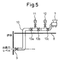
- FIG. 5 is an explanatory diagram showing an embodiment of the present invention.
- FIG. 6 is a diagram showing a comparison of the long life span.
- FIG. 7 is a diagram showing a comparison of the life span of the Otsuka cover.
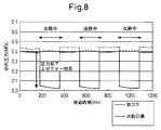
- FIG. 8 is a view showing the furnace pressure fluctuation at the time of tapping.
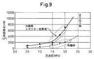
- FIG. 9 is a diagram showing the relationship between the press-fit pressure and the press-fit viscosity.
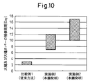
- FIG. 10 is a comparative view of the duration of the sealing effect due to the press-fitting material press-fitting.
- FIG. 3 the schematic explanatory drawing of the blast furnace rough slag suppression method of this invention is shown.
- FIG. 4 the position explanatory drawing of the press-fit hole provided beside the tap hole used for this invention is shown.
- FIG. 5 shows an embodiment of the present invention.
- FIG. 3 schematically shows a blast furnace lining cross section and a press-fitting machine 7.
- a press-fitting hole 9 next to the tap hole 6 is installed in the circumferential direction of the blast furnace as viewed from the tap hole, and is connected via a pipe 10 to a press-fitting machine 7 having a pump, a motor and the like for press-fitting the press-fitting material.
- the press-fitting material is press-fitted into the press-fitting hole 9 through the pipe 10 by the pressure of the press-fitting machine 7. Regardless of the case of press-fitting from the press-fitting hole provided on the side of the tap hole 6, regardless of the case of press-fitting from the press-fitting hole provided below the tuyere, the hot metal at the time of pouring is taken into consideration for the safety of workers and the protection of equipment
- the press-fitting machine 7 is installed in the tuyere deck 8 where the scattering does not reach.
- FIG. 4 schematically shows a horizontal cross section in the blast furnace at the level of the tap hole of the blast furnace. As shown in FIG.
- the press-fitting hole 9 is provided at a position of 0.5 to 4 m around the tap hole.
- the pipe 10 connected to the press-fitting hole 9 installed beside the sprue hole 6 is damaged by the hot metal scattered from the spigot hole.
- the installation position of the press-fitting hole 9 is further than 4 m from the periphery of the tap hole 6, it is difficult to press-fit a high-viscosity press-fit material because the pressure drop in the furnace due to the ejector effect at the time of taping cannot be obtained sufficiently. It becomes.
- the highly viscous press-fit material used in the present invention is a press-fit material having a viscosity of 2000 to 7000 cP, and for example, a kneaded product of a furan resin and graphite can be used as the highly viscous press-fit material.
- the physical properties required as a press-fitting material for suppressing roughening and wrinkling are that the powder and resin do not separate and shrink even when contacted with a high-temperature gas around 350 ° C.
- the press-fit material (viscosity 2000 to 7000 cP) used in the present invention has the physical properties. It has.
- the present invention is characterized in that the press-fitting material having a viscosity of 2000 to 7000 cP is subjected to press-fitting during brewing.
- FIGS. FIG. 8 shows the furnace pressure fluctuation at the time of tapping
- FIG. 9 shows the relationship between press-fit pressure and press-fit viscosity. As shown in FIG.
- the pressure around the tap hole which was about 0.4 MPa during the stand-by standby, greatly decreases to 0.1 MPa or less during the start-up. That is, at the time of extraction, a large suction force works around the exit hole.
- the present invention is characterized in that a high-viscosity press-fitting material is press-fitted from a press-fitting hole provided on the side of the tap hole using this suction force.
- the appropriate pumping pressure at the time of brewing standby furnace pressure of about 0.4 MPa
- a press-fitting material having a viscosity of 1000 to 2000 cP or more is press-fitted at the pressure. I can't.
- a press-fitting material of 2000 to 7000 cP is applied under an appropriate pumping pressure of 1.5 to 2 MPa by utilizing an ejector effect in which the pressure around the tap hole is greatly reduced to 0.1 MPa or less at the time of tapping. It was possible to press fit and succeeded in greatly improving the gas sealing effect in the furnace.
- the press-fitting material is filled in the blast furnace lining back gap, there is a concern that the press-fitting material may flow backward depending on the press-fitting pressure and the pressure in the furnace.
- the timing of ejector effect generation differs depending on the press-fitting pipe.
- a valve 13a, a pressure gauge A11, a valve 13b, a pressure gauge B12, and a valve 13c are provided between the extension pipe 10 and the press-fitting machine 7 to adjust the press-fitting timing. It can. Specifically, first, only the valve 13a is released, and the pressure in the furnace is measured by the pressure gauge A11 with the valves 13b and 13c closed, and a rapid decrease in the furnace pressure as shown in FIG. Occurrence).
- the valve 13c is also opened, and after confirming that the pressure indicated by the pressure gauge B12 exceeds the in-furnace blowing pressure, the valve 13b is opened.
- the highly viscous press-fit material has an effect of improving the gas sealing property, but after the press-fit, the press-fit material is blocked in the extension pipe 10 or around the inside of the press-fit hole 9 furnace, so that repeated press-fit becomes difficult.
- the present invention there is a method in which the above method and a method of press-fitting a low-viscosity press-fit material from a press-fit hole provided under a tuyere are used.
- the low-viscosity press-fit material is simply press-fitted from the press-fit hole provided under the tuyere, the low-viscosity press-fit material with an emphasis on fluidity flows into the spout hole, and the sealing performance decreases.
- a press-fitting hole with an inner diameter of 40A is provided on each of the left and right positions at a position 2 m in the circumferential direction of the furnace from the tap hole of the blast furnace having a furnace internal volume of 5400 m 3 .
- a press-fitting machine was installed on the tuyere deck where the molten iron was not scattered, and it was press-fitted from one or two press-fitting holes provided next to the spout hole in one press-fitting operation.
- the press-fitting material was a kneaded mixture of furan resin and graphite having a viscosity of 3000 to 5000 cP, and about 100 kg was used for one press-fitting hole.
- press-fitting In press-fitting, the above-mentioned pressure check and valve operation were carried out while the ejector was expected to have an ejector effect, and press-fitting was performed at a press-fitting pressure of 1.2 to 1.5 MPa. Since the gas in the furnace mixes with the output flow in the output hole and the output flow is disturbed, the cover of the output hole in the output hole is damaged. As a result of confirming the life of the cover and cover by press-fitting, as shown in FIG. 6, the cover has an output amount of 90,000 tons, and the cover has an output amount of 50,000 tons as shown in FIG. Thus, the in-furnace gas sealing effect by press-fitting continued for 7 to 12 days.
- press-fitting holes with an inner diameter of 40A are provided under the tuyere of the blast furnace over the entire circumference of the furnace.
- the press machine was installed in the tuyere deck where the molten iron was not scattered, and it was press-fitted from the press-fit holes provided under about 10 tuyere in one press-fitting operation.
- the press-fitting material was a kneaded mixture of furan resin and graphite having a viscosity of 1000 cP, and about 100 kg was used for one press-fitting hole.
- press-fitting the above-mentioned pressure check and valve operation were carried out during operation, and press-fitting was performed at a press-fitting pressure of 1.5 to 1.8 MPa.
- the press machine was installed in the tuyere deck where the molten iron was not scattered, and it was press-fitted from the press-fit holes provided under about 10 tuyere in one press-fitting operation.
- the press-fitting material was a kneaded mixture of furan resin and graphite having a viscosity of 1000 cP, and about 100 kg was used for one press-fitting hole.
- press-fitting the above-mentioned pressure check and valve operation were carried out during operation, and press-fitting was performed at a press-fitting pressure of 1.5 to 1.8 MPa.
- the cover has an output amount of 70,000 tons
- the cover has an output amount of 30,000 tons as shown in FIG.
- the gas sealing effect in the furnace by press-fitting continued for 2 to 3 days.
- the problems of the prior art are solved, and in the gap between the blast furnace lining back surface, the vicinity of the tap hole that is the gas gas outlet in the furnace is securely filled, and the gas sealing effect in the furnace by the press-fitting material filling is achieved.
- a method for suppressing rough sag which can be maintained for a long period of time.
Landscapes
- Engineering & Computer Science (AREA)
- Chemical & Material Sciences (AREA)
- Mechanical Engineering (AREA)
- General Engineering & Computer Science (AREA)
- Manufacturing & Machinery (AREA)
- Materials Engineering (AREA)
- Metallurgy (AREA)
- Organic Chemistry (AREA)
- Blast Furnaces (AREA)
- Furnace Housings, Linings, Walls, And Ceilings (AREA)
Abstract
Description
このような現象に対して従来の高炉荒れ出銑抑制方法は、特許第2617859号公報に記載の羽口下に設けられた圧入孔に圧入材を圧入して、高炉ライニング背面隙間を充填するものであった。しかしながら、一般的には羽口から出銑孔までの距離は5.0m以上あり、高い流動性を有する低粘性の圧入材を圧入しても、圧入材が出銑孔付近の隙間まで到達せず、望ましい充填効果が得られない問題があった。また、低粘性圧入材に含まれる液体分が熱によって揮発し、圧入材が収縮したり、低粘性であるが故に一部のガス流出経路から圧入材が出銑孔に流出してしまい、高炉ライニング背面隙間の充填に用いた圧入材による炉内ガスシール効果が短期間で低下してしまう問題があった。
一方で、炉内ガスシール効果の高い高粘性圧入材を使用した場合は、圧入孔または圧入配管の閉塞が問題となり、圧入材の圧入圧力を高めて圧入すると図1に記すような内張りれんが1を押し出す等、高炉炉壁を損傷させる懸念があるため、設備保護上の観点から圧入圧力を高めて高粘性圧入材を圧入することが困難であった。
上記課題を解決するために、本発明に係る高炉荒れ出銑抑制方法の要旨は、下記のとおりである。
(1)出銑孔横に設けた圧入孔から、出銑孔周辺部の高炉ライニング背面隙間へ、高粘性圧入材を圧入する高炉荒れ出銑抑制方法であって、粘性2000~7000cPの高粘性圧入材を、出銑中に出銑孔近傍に生じるエゼクター効果を利用して圧入することを特徴とする。
(2)上記(1)記載の高炉荒れ出銑抑制方法において、圧入孔を出銑孔の周囲0.5~4mの位置に設けたことを特徴とする。
(3)上記(1)または(2)記載の高炉荒れ出銑抑制方法において、炉内圧力検出手段によりエゼクター効果の発生を検出し、エゼクター効果発生確認後に圧入を開始することを特徴とする。
(4)上記(1)~(3)の何れかに記載の高炉荒れ出銑抑制方法において、高粘性圧入材圧入後に、樹脂のみの圧入を行うことを特徴とする。
(5)上記(1)~(4)の何れかに記載の高炉荒れ出銑抑制方法において、羽口下に設けた圧入孔から粘性20~2000cPの低粘性圧入材の圧入を組み合わせて行うことを特徴とする。
従来の高炉荒れ出銑抑制方法では、羽口下に設けられた圧入孔から粘性20~2000cPの低粘性圧入材を圧入する方法が採用されていた。これに対し、本発明では、出銑孔横に設けた圧入孔から粘性2000~7000cPの高粘性圧入材を圧入することにより、高炉ライニング背面隙間のうち、炉内ガス漏風出口である出銑孔付近を確実に充填し、かつ圧入材充填による炉内ガスシール効果を長期間維持することを可能とした。
なお、圧入材の粘度を高めると、前記のとおり、圧入孔または圧入配管が閉塞することが問題となり、また設備保護上の観点から圧入圧力の制約があるため、従来の方法では粘度2000cP以上の圧入材を用いることはできなかったが、本発明では、高炉出銑時に出銑孔付近の炉内圧力が低下し、出銑孔付近へ向かう吸引力が生じること(以下、エゼクター効果)を利用して、出銑中に圧入を行うことにより粘度2000~7000cPの高粘性圧入材の使用を可能とした。
本発明の望ましい形態によれば、圧入孔は出銑孔の周囲0.5~4mの位置に設け、出銑孔の近距離からの圧入を行うことにより、炉内ガス漏風出口である出銑孔付近を、より確実に充填することを可能とした。
本発明の他の望ましい形態によれば、炉内圧力検出手段によりエゼクター効果の発生を検出し、エゼクター効果発生確認後に圧入を開始することにより、圧入材の逆流を防止し圧入材を高炉ライニング背面隙間に確実に充填することができる。
本発明の更に他の望ましい形態によれば、高粘性圧入材圧入後に樹脂のみの圧入を行うことにより、圧入材圧入用配管内及び圧入孔炉内側周囲に付着した高粘性圧入材が樹脂で置換される。これにより、圧入材圧入用配管内及び圧入孔炉内側周囲の詰まりが防止可能となった。また、次回の高粘性圧入材圧入時には圧入配管内壁面に残存する低粘性の樹脂によって、高粘性圧入材を圧入する際の配管内摩擦を軽減することができる。このため、圧入材を効率的に圧入することができる。
本発明の更に別の望ましい形態によれば、羽口下に設けた圧入孔から粘性20~2000cPの低粘性圧入材の圧入を組み合わせて行うことにより、炉内ガスが前記高粘性圧入材が充填されたシール部分に直接吹き込むことによるシール部分の損傷を防止した。これにより、炉内ガスシール効果を長期間維持することを可能となる。
図2は、「高炉荒れ出銑」の原因となる炉内ガス流出経路の説明図である。
図3は、本発明の高炉荒れ出銑抑制方法の概略説明図である。
図4は、本発明に用いる出銑孔横に設けた圧入孔の位置説明図である。
図5は、本発明の一実施形態を示す説明図である。
図6は、大樋寿命の比較を示す図である。
図7は、大樋カバー寿命の比較を示す図である。
図8は、出銑時の炉圧力変動を示す図である。
図9は、圧入圧と圧入可能粘度の関係を示す図である。
図10は、圧入材圧入によるシール効果の継続期間の比較図である。
図3には、本発明の高炉荒れ出銑抑制方法の概略説明図を示している。図4には、本発明に用いる出銑孔横に設けた圧入孔の位置説明図を示している。図5には、本発明の一実施形態を示している。
図3は高炉ライニング断面と圧入機7を模式的に示している。出銑孔6の横の圧入孔9は出銑孔からみて高炉円周方向に設置されており、圧入材を圧入するためのポンプ、モーター等を有する圧入機7と配管10を介して接続される。圧入材は圧入機7による圧力によって、配管10を通して圧入孔9へ圧入される。出銑孔6横に設けた圧入孔から圧入する場合、羽口下に設けた圧入孔から圧入する場合に関わらず、作業員の安全と設備の保護を考慮して、出銑時の溶銑の飛散が及ばない羽口デッキ8に圧入機7を設置する。
図4は、高炉の出銑孔のレベルにおける高炉炉内水平断面を模式的に示している。 図4に示すように、前記圧入孔9は、出銑孔の周囲0.5~4mの位置に設けられている。圧入孔9の設置位置が出銑孔6の周囲0.5mより近い場合は、出銑孔6横に設置された圧入孔9に接続される配管10が、出銑孔から飛散する溶銑により損傷する懸念がある。また、圧入孔9の設置位置が出銑孔6の周囲4mより遠い場合は、出銑時のエゼクター効果による炉内圧力低下が十分に得られないため、高粘性圧入材を圧入することが困難となる。このため、圧入孔9は出銑孔6横の周囲0.5~4mの位置に設置することが望ましい。
本発明に用いられる高粘性圧入材は粘性2000~7000cPの圧入材であり、当該高粘性圧入材は、例えばフラン系樹脂と黒鉛の混練物を用いることができる。なお、荒れ出銑抑制用圧入材として求められる物性とは、350℃付近の高温ガスに接触した場合でも、粉体と樹脂が分離して収縮することなく、また反対に、揮発ガスを内部に取り込んで膨張することもなく、ガスシールに最適な緻密性を維持可能であること、及び、高い熱伝導性を有することであり、本発明に用いる圧入材(粘性2000~7000cP)は当該物性を具備するものである。
本発明は、粘性2000~7000cPの圧入材を圧入可能とするために、出銑中に圧入を行うことを特徴とするものである。以下、図8及び図9に基づいて当該特徴につき説明する。図8には出銑時の炉圧力変動を示し、図9には圧入圧と圧入可能粘度の関係を示している。
図8に示すように、出銑待機中には約0.4MPaであった出銑孔周囲の圧力が、出銑時には0.1MPa以下へと大きく低下する。すなわち、出銑時に出銑孔周囲では吸引力が大きく働いている。本発明は、この吸引力を利用して高粘性の圧入材を出銑孔横に設けた圧入孔から圧入することを特徴とするものである。なお、図9に示すように、出銑待機時(炉内圧約0.4MPa)の適正圧送圧は1.5~2MPaであり、当該圧力では1000~2000cP以上の粘性の圧入材を圧入することはできない。一方、本発明では、出銑時に出銑孔周囲の圧力が0.1MPa以下へと大きく低下するエゼクター効果を利用して、1.5~2MPaの適正圧送圧下において、2000~7000cPの圧入材を圧入可能とし、炉内ガスシール効果を大きく改善することに成功した。
高炉ライニング背面隙間に圧入材を充填する場合、圧入圧力と炉内圧力によっては圧入材が逆流する懸念がある。また、圧入管によってエゼクター効果発生のタイミングが異なる。このため、炉内圧力を測定することによってエゼクター効果の発生タイミングを検知し、圧入することが必要となる。例えば、図5に示すように、延長配管10と圧入機7との間に弁13aと、圧力計A11と、弁13bと、圧力計B12と、弁13cを設けて圧入タイミング調整を行うことができる。具体的には、まず弁13aのみ解放し、弁13bと弁13cとは閉じた状態で、圧力計A11により炉内圧力を測定し、図8に示すような炉内圧の急激な低下(エゼクター効果の発生)を確認する。エゼクター効果の発生が確認された後、弁13cも開放して圧力計B12の示す圧力が炉内送風圧力を超えたことを確認した後に弁13bを開放する。これにより、圧入材の逆流を防止することとともに、エゼクター効果発生のタイミングを検知し炉内圧力低下後に圧入することができる。
高粘性圧入材はガスシール性が向上するという効果を有するが、圧入後に延長配管10内や圧入孔9炉内側周囲で圧入材が閉塞してしまい、繰り返し圧入が困難になる。これに対し、高粘性圧入材圧入終了後、樹脂のみを圧入して配管内に充填させることで、圧入材圧入用配管内及び圧入孔炉内側周囲の詰まりを防止している。また、次回の高粘性圧入材圧入時には圧入配管内壁面に残存する低粘性の樹脂によって、高粘性圧入材を圧入する際の配管内摩擦を軽減することができる。このため、圧入材で配管を閉塞させることなく効率的に圧入することができる。
本発明の他の実施形態としては、上記方法と羽口下に設けた圧入孔から低粘性圧入材を圧入する方法とを併用する方法がある。前記のように、羽口下に設けた圧入孔から低粘性圧入材を圧入するのみでは、流動性重視の低粘性圧入材が出銑孔に流入し、シール性が低下していく。一方、出銑孔横に設けた圧入孔から高粘性圧入材を圧入した場合、前記問題は解消するものの、羽口下から炉内ガス流出経路を通ってガスが吹き込み、シール部分を除々に損傷する問題が発生する。これに対し、羽口下に設けた圧入孔から粘性20~2000cPの低粘性圧入材の圧入を組み合わせて行うことにより、炉内ガスが前記高粘性圧入材が充填されたシール部分に直接吹き込むことによるシール部分の損傷を防止可能となった。
比較例1
前記の高炉の羽口下に炉全周にわたって、内径40Aの圧入孔が42箇所設置されている。圧入機を溶銑の飛散が及ばない羽口デッキに設置し、1回の圧入作業で10箇所程度の羽口下に設けられた圧入孔から圧入した。圧入材はフラン系樹脂と黒鉛の混練物であって、1000cPの粘度を有するものを、1箇所の圧入孔に対して約100kg使用した。圧入にあたっては、操業中に前記の圧力確認と弁操作を実施し、圧入圧力1.5~1.8MPaで圧入した。圧入による大樋、カバーの寿命を確認した結果、図6に示すように大樋は出銑量7.0万トン、図7に示すようにカバーは出銑量3.0万トンであり、図10に示すように圧入による炉内ガスシール効果は、2~3日間継続した。
2 スタンプ層
3 ステーブ
4 鉄皮
5 羽口
6 出銑孔
7 圧入機
8 羽口デッキ
9 圧入孔
10 延長配管
11 圧力計A
12 圧力計B
13a~13c ボール弁
Claims (5)
- 出銑孔横に設けた圧入孔から、出銑孔周辺部の高炉ライニング背面隙間へ、高粘性圧入材を圧入する高炉荒れ出銑抑制方法であって、
粘性2000~7000cPの高粘性圧入材を、出銑中に出銑孔近傍に生じるエゼクター効果を利用して圧入することを特徴とする高炉荒れ出銑抑制方法。 - 圧入孔は、出銑孔の周囲0.5~4mの位置に設けたことを特徴とする請求項1記載の高炉荒れ出銑抑制方法。
- 炉内圧力検出手段によりエゼクター効果の発生を検出し、エゼクター効果発生確認後に圧入を開始することを特徴とする請求項1または2記載の高炉荒れ出銑抑制方法。
- 高粘性圧入材圧入後に、樹脂のみの圧入を行うことを特徴とする請求項1~3の何れかに記載の高炉荒れ出銑抑制方法。
- 羽口下に設けた圧入孔から粘性20~2000cPの低粘性圧入材の圧入を組み合わせて行うことを特徴とする請求項1~4の何れかに記載の高炉荒れ出銑抑制方法。
Priority Applications (3)
| Application Number | Priority Date | Filing Date | Title |
|---|---|---|---|
| KR1020117002224A KR101235550B1 (ko) | 2008-08-28 | 2009-08-21 | 고로 거친 출선 억제 방법 |
| CN2009801219564A CN102057057B (zh) | 2008-08-28 | 2009-08-21 | 高炉不稳定出铁抑制方法 |
| BRPI0917177-0A BRPI0917177B1 (pt) | 2008-08-28 | 2009-08-21 | High-oven irregular leak suppression method |
Applications Claiming Priority (2)
| Application Number | Priority Date | Filing Date | Title |
|---|---|---|---|
| JP2008-219144 | 2008-08-28 | ||
| JP2008219144A JP4516995B2 (ja) | 2008-08-28 | 2008-08-28 | 高炉荒れ出銑抑制方法 |
Publications (1)
| Publication Number | Publication Date |
|---|---|
| WO2010024360A1 true WO2010024360A1 (ja) | 2010-03-04 |
Family
ID=41721525
Family Applications (1)
| Application Number | Title | Priority Date | Filing Date |
|---|---|---|---|
| PCT/JP2009/065011 Ceased WO2010024360A1 (ja) | 2008-08-28 | 2009-08-21 | 高炉荒れ出銑抑制方法 |
Country Status (5)
| Country | Link |
|---|---|
| JP (1) | JP4516995B2 (ja) |
| KR (1) | KR101235550B1 (ja) |
| CN (1) | CN102057057B (ja) |
| BR (1) | BRPI0917177B1 (ja) |
| WO (1) | WO2010024360A1 (ja) |
Families Citing this family (1)
| Publication number | Priority date | Publication date | Assignee | Title |
|---|---|---|---|---|
| CN102719583A (zh) * | 2012-07-03 | 2012-10-10 | 鞍钢集团工程技术有限公司 | 一种延长高炉炉缸、炉底寿命的方法 |
Citations (4)
| Publication number | Priority date | Publication date | Assignee | Title |
|---|---|---|---|---|
| JPS63297487A (ja) * | 1987-05-29 | 1988-12-05 | Harima Ceramic Co Ltd | 間隙部充填用圧入材 |
| JPH0535841U (ja) * | 1991-10-16 | 1993-05-14 | 住友金属工業株式会社 | 高炉出銑口の耐火物補修装置 |
| JPH06100913A (ja) * | 1992-09-18 | 1994-04-12 | Nippon Steel Corp | 精錬容器の圧入補修方法 |
| JPH11293310A (ja) * | 1998-04-13 | 1999-10-26 | Nippon Steel Corp | 高炉炉底側壁補修方法及び装置 |
Family Cites Families (4)
| Publication number | Priority date | Publication date | Assignee | Title |
|---|---|---|---|---|
| JPS527308A (en) * | 1975-07-08 | 1977-01-20 | Sumitomo Metal Ind Ltd | Method and apparatus for gas sealing of tap hole in blast furnaces |
| SE434650B (sv) * | 1982-06-09 | 1984-08-06 | Skf Steel Eng Ab | Sett vid utnyttjande av plasmagenerator for hojning av blestertemperaturen i en schaktugn |
| JPH0535841A (ja) * | 1991-07-31 | 1993-02-12 | Toshiba Corp | 画像記憶装置 |
| JPH11229011A (ja) * | 1998-02-16 | 1999-08-24 | Kawasaki Steel Corp | 高炉炉体の補修方法 |
-
2008
- 2008-08-28 JP JP2008219144A patent/JP4516995B2/ja active Active
-
2009
- 2009-08-21 BR BRPI0917177-0A patent/BRPI0917177B1/pt not_active IP Right Cessation
- 2009-08-21 CN CN2009801219564A patent/CN102057057B/zh not_active Expired - Fee Related
- 2009-08-21 WO PCT/JP2009/065011 patent/WO2010024360A1/ja not_active Ceased
- 2009-08-21 KR KR1020117002224A patent/KR101235550B1/ko not_active Expired - Fee Related
Patent Citations (4)
| Publication number | Priority date | Publication date | Assignee | Title |
|---|---|---|---|---|
| JPS63297487A (ja) * | 1987-05-29 | 1988-12-05 | Harima Ceramic Co Ltd | 間隙部充填用圧入材 |
| JPH0535841U (ja) * | 1991-10-16 | 1993-05-14 | 住友金属工業株式会社 | 高炉出銑口の耐火物補修装置 |
| JPH06100913A (ja) * | 1992-09-18 | 1994-04-12 | Nippon Steel Corp | 精錬容器の圧入補修方法 |
| JPH11293310A (ja) * | 1998-04-13 | 1999-10-26 | Nippon Steel Corp | 高炉炉底側壁補修方法及び装置 |
Also Published As
| Publication number | Publication date |
|---|---|
| JP2010053396A (ja) | 2010-03-11 |
| CN102057057B (zh) | 2013-04-10 |
| KR20110023909A (ko) | 2011-03-08 |
| BRPI0917177B1 (pt) | 2017-09-12 |
| JP4516995B2 (ja) | 2010-08-04 |
| CN102057057A (zh) | 2011-05-11 |
| BRPI0917177A2 (pt) | 2015-11-10 |
| KR101235550B1 (ko) | 2013-02-21 |
Similar Documents
| Publication | Publication Date | Title |
|---|---|---|
| CN102617157B (zh) | 一种炮泥及其制备方法 | |
| AU2015215190B9 (en) | Pneumatic ore charging | |
| KR20210123387A (ko) | 로저의 승온 방법 및 그것에 이용하는 버너 랜스 | |
| JP4516995B2 (ja) | 高炉荒れ出銑抑制方法 | |
| CN206112363U (zh) | 一种用于高温高压条件使用的耐磨三通 | |
| KR101562451B1 (ko) | 스테이브 냉각 파이프용 보수재 및 보수방법 | |
| CN104110541A (zh) | 高压设备的法兰面和密封垫片泄漏处封堵方法及其装置 | |
| JP2013091838A (ja) | 高炉送風羽口保持金物のガスシール構造及びガスシール方法 | |
| CN204569952U (zh) | 液压炮打泥机构 | |
| JP2011206827A (ja) | ダイカストマシンのプランジャースリーブ構造 | |
| CN100425705C (zh) | 一种炼铁高炉冷却壁冷却管道内堵漏方法 | |
| CN204226644U (zh) | 多齿辊卸料机密封装置 | |
| JP2023141704A (ja) | 高炉におけるステーブクーラーの設置方法およびステーブクーラーの設置構造 | |
| CN109423531A (zh) | 一种高炉铁口异常堵口装置及其使用方法 | |
| JP2019100616A (ja) | マッドガン | |
| JP2009160592A (ja) | 金属成形用射出装置の射出シリンダ | |
| JP4105983B2 (ja) | 高炉鉄皮の補修方法 | |
| KR100822971B1 (ko) | 보조재를 이용한 용광로의 출선구 폐쇄방법 | |
| CN217418740U (zh) | 一种矿热炉炉壁外部注浆造衬专用工具 | |
| KR102112537B1 (ko) | 고로 노체 냉각 장치 | |
| KR101650407B1 (ko) | 고로 출선구 충전용 충진재 및 이를 이용한 충진방법 | |
| EP1233077A1 (en) | System for repairing blast furnace taphole facings | |
| JP7417610B2 (ja) | シャフト炉の内壁を保護する方法 | |
| CN202530097U (zh) | 一种能抑制炉缸侧壁温度上升的铁口孔道灌浆专用工具 | |
| CN116287517A (zh) | 欧冶炉全氧冶炼铁水的高温熔融渣铁排口及出渣方法 |
Legal Events
| Date | Code | Title | Description |
|---|---|---|---|
| WWE | Wipo information: entry into national phase |
Ref document number: 200980121956.4 Country of ref document: CN |
|
| 121 | Ep: the epo has been informed by wipo that ep was designated in this application |
Ref document number: 09810010 Country of ref document: EP Kind code of ref document: A1 |
|
| WWE | Wipo information: entry into national phase |
Ref document number: 8914/DELNP/2010 Country of ref document: IN |
|
| ENP | Entry into the national phase |
Ref document number: 20117002224 Country of ref document: KR Kind code of ref document: A |
|
| NENP | Non-entry into the national phase |
Ref country code: DE |
|
| 122 | Ep: pct application non-entry in european phase |
Ref document number: 09810010 Country of ref document: EP Kind code of ref document: A1 |
|
| ENP | Entry into the national phase |
Ref document number: PI0917177 Country of ref document: BR Kind code of ref document: A2 Effective date: 20110225 |