WO2010023728A1 - 圧電振動子の製造方法、圧電振動子、発振器、電子機器および電波時計 - Google Patents
圧電振動子の製造方法、圧電振動子、発振器、電子機器および電波時計 Download PDFInfo
- Publication number
- WO2010023728A1 WO2010023728A1 PCT/JP2008/065247 JP2008065247W WO2010023728A1 WO 2010023728 A1 WO2010023728 A1 WO 2010023728A1 JP 2008065247 W JP2008065247 W JP 2008065247W WO 2010023728 A1 WO2010023728 A1 WO 2010023728A1
- Authority
- WO
- WIPO (PCT)
- Prior art keywords
- pair
- piezoelectric vibrator
- piezoelectric
- vibrating
- vibrating arm
- Prior art date
- Legal status (The legal status is an assumption and is not a legal conclusion. Google has not performed a legal analysis and makes no representation as to the accuracy of the status listed.)
- Ceased
Links
Images










Classifications
-
- H—ELECTRICITY
- H03—ELECTRONIC CIRCUITRY
- H03H—IMPEDANCE NETWORKS, e.g. RESONANT CIRCUITS; RESONATORS
- H03H3/00—Apparatus or processes specially adapted for the manufacture of impedance networks, resonating circuits, resonators
- H03H3/007—Apparatus or processes specially adapted for the manufacture of impedance networks, resonating circuits, resonators for the manufacture of electromechanical resonators or networks
- H03H3/02—Apparatus or processes specially adapted for the manufacture of impedance networks, resonating circuits, resonators for the manufacture of electromechanical resonators or networks for the manufacture of piezoelectric or electrostrictive resonators or networks
- H03H3/04—Apparatus or processes specially adapted for the manufacture of impedance networks, resonating circuits, resonators for the manufacture of electromechanical resonators or networks for the manufacture of piezoelectric or electrostrictive resonators or networks for obtaining desired frequency or temperature coefficient
-
- H—ELECTRICITY
- H03—ELECTRONIC CIRCUITRY
- H03H—IMPEDANCE NETWORKS, e.g. RESONANT CIRCUITS; RESONATORS
- H03H9/00—Networks comprising electromechanical or electro-acoustic elements; Electromechanical resonators
- H03H9/02—Details
- H03H9/05—Holders or supports
- H03H9/10—Mounting in enclosures
- H03H9/1007—Mounting in enclosures for bulk acoustic wave [BAW] devices
- H03H9/1014—Mounting in enclosures for bulk acoustic wave [BAW] devices the enclosure being defined by a frame built on a substrate and a cap, the frame having no mechanical contact with the BAW device
- H03H9/1021—Mounting in enclosures for bulk acoustic wave [BAW] devices the enclosure being defined by a frame built on a substrate and a cap, the frame having no mechanical contact with the BAW device the BAW device being of the cantilever type
-
- H—ELECTRICITY
- H03—ELECTRONIC CIRCUITRY
- H03H—IMPEDANCE NETWORKS, e.g. RESONANT CIRCUITS; RESONATORS
- H03H9/00—Networks comprising electromechanical or electro-acoustic elements; Electromechanical resonators
- H03H9/15—Constructional features of resonators consisting of piezoelectric or electrostrictive material
- H03H9/21—Crystal tuning forks
- H03H9/215—Crystal tuning forks consisting of quartz
-
- H—ELECTRICITY
- H03—ELECTRONIC CIRCUITRY
- H03H—IMPEDANCE NETWORKS, e.g. RESONANT CIRCUITS; RESONATORS
- H03H3/00—Apparatus or processes specially adapted for the manufacture of impedance networks, resonating circuits, resonators
- H03H3/007—Apparatus or processes specially adapted for the manufacture of impedance networks, resonating circuits, resonators for the manufacture of electromechanical resonators or networks
- H03H3/02—Apparatus or processes specially adapted for the manufacture of impedance networks, resonating circuits, resonators for the manufacture of electromechanical resonators or networks for the manufacture of piezoelectric or electrostrictive resonators or networks
- H03H2003/026—Apparatus or processes specially adapted for the manufacture of impedance networks, resonating circuits, resonators for the manufacture of electromechanical resonators or networks for the manufacture of piezoelectric or electrostrictive resonators or networks the resonators or networks being of the tuning fork type
-
- H—ELECTRICITY
- H03—ELECTRONIC CIRCUITRY
- H03H—IMPEDANCE NETWORKS, e.g. RESONANT CIRCUITS; RESONATORS
- H03H3/00—Apparatus or processes specially adapted for the manufacture of impedance networks, resonating circuits, resonators
- H03H3/007—Apparatus or processes specially adapted for the manufacture of impedance networks, resonating circuits, resonators for the manufacture of electromechanical resonators or networks
- H03H3/02—Apparatus or processes specially adapted for the manufacture of impedance networks, resonating circuits, resonators for the manufacture of electromechanical resonators or networks for the manufacture of piezoelectric or electrostrictive resonators or networks
- H03H3/04—Apparatus or processes specially adapted for the manufacture of impedance networks, resonating circuits, resonators for the manufacture of electromechanical resonators or networks for the manufacture of piezoelectric or electrostrictive resonators or networks for obtaining desired frequency or temperature coefficient
- H03H2003/0414—Resonance frequency
- H03H2003/0492—Resonance frequency during the manufacture of a tuning-fork
-
- Y—GENERAL TAGGING OF NEW TECHNOLOGICAL DEVELOPMENTS; GENERAL TAGGING OF CROSS-SECTIONAL TECHNOLOGIES SPANNING OVER SEVERAL SECTIONS OF THE IPC; TECHNICAL SUBJECTS COVERED BY FORMER USPC CROSS-REFERENCE ART COLLECTIONS [XRACs] AND DIGESTS
- Y10—TECHNICAL SUBJECTS COVERED BY FORMER USPC
- Y10T—TECHNICAL SUBJECTS COVERED BY FORMER US CLASSIFICATION
- Y10T29/00—Metal working
- Y10T29/42—Piezoelectric device making
Definitions
- the present invention relates to a surface mount type (SMD) piezoelectric vibrator in which a piezoelectric vibrating piece is sealed in a cavity formed between two bonded substrates, a manufacturing method thereof, an oscillator having a piezoelectric vibrator,
- SMD surface mount type
- the present invention relates to electronic devices and radio clocks.
- a piezoelectric vibrator using crystal or the like is used as a timing source such as a time source or a control signal, a reference signal source, or the like in a mobile phone or a portable information terminal.
- a timing source such as a time source or a control signal, a reference signal source, or the like in a mobile phone or a portable information terminal.
- Various types of piezoelectric vibrators of this type are known, and one of them is a surface mount type (SMD, Surface Mount Device) piezoelectric vibrator.
- SMD Surface Mount Device
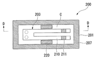
- FIG. 18 is a plan view of the piezoelectric vibrator according to the prior art with the lid substrate removed
- FIG. 19 is a cross-sectional view taken along the line DD of FIG.
- a package 209 is formed by a base substrate 201 and a lid substrate 202, and the piezoelectric vibrating piece 203 is housed in a cavity C formed inside the package 209. Things have been proposed.
- the base substrate 201 and the lid substrate 202 are bonded by anodic bonding with a bonding film 207 disposed therebetween.
- a piezoelectric vibrator having a lower equivalent resistance value (effective resistance value, Re) is desired.
- a piezoelectric vibrator having a low equivalent resistance value can vibrate the piezoelectric vibrating piece with low power, and thus becomes a piezoelectric vibrator with good energy efficiency.
- the cavity C in which the piezoelectric vibrating piece 203 is sealed is brought close to a vacuum, and the series is proportional to the equivalent resistance value.
- a method of reducing the resonance resistance value (R1) is known.
- the getter material 220 and the gettering are placed on the vibrating arm portion 210 of the piezoelectric vibrating piece 203 positioned in the immediate vicinity of the getter material 220.
- the amount of the getter material 220 adhering to each of the pair of vibrating arm portions 210 and 210 becomes unbalanced, vibration leakage (vibration of leakage of vibration energy) occurs and the characteristics of the piezoelectric vibrator become unstable. was there. As a result, there is a problem that the yield of the piezoelectric vibrator 200 is lowered.
- the present invention has been made in view of the above-described circumstances, and provides a piezoelectric vibrator capable of reducing vibration leakage and improving yield, a manufacturing method thereof, an oscillator, an electronic device, and a radio timepiece. With the goal.
- the piezoelectric vibrator manufacturing method according to the present invention corresponds to each of the tuning fork-type piezoelectric vibrating piece having a pair of vibrating arms, a package housing the piezoelectric vibrating pieces, and the pair of vibrating arms.
- the method includes a gettering step of irradiating the laser at a symmetrical position via a central axis of the pair of vibrating arms in the pair of adjustment films. It is characterized by that.
- the piezoelectric vibrator according to the present invention includes a tuning fork-type piezoelectric vibrating piece provided with a pair of vibrating arm portions, a package housing the piezoelectric vibrating piece, and the vibration corresponding to each of the pair of vibrating arm portions.
- a pair of adjustment films formed along the longitudinal direction of the arm, and improving the degree of vacuum in the package by irradiating the adjustment film with a laser to evaporate a part of the adjustment film
- the laser irradiation traces are formed at symmetrical positions via the central axes of the pair of vibrating arms in the pair of adjustment films.
- a part of the adjustment film is evaporated by irradiating a laser at a symmetrical position via the central axis of the pair of vibrating arms in the pair of adjustment films.
- the adjustment film deposited on the side surfaces of the pair of vibrating arms can be made substantially uniform.
- the vibration characteristics of the vibrating arms change depending on the gettering position in the longitudinal direction of the vibrating arms, but the vibration characteristics of the pair of vibrating arms are matched by gettering to a symmetrical position via the central axis. Can do. Therefore, stable vibration characteristics can be obtained even after the gettering step, and vibration leakage can be reduced. As a result, the yield can be improved.
- the oscillator according to the present invention is characterized in that the above-described piezoelectric vibrator is electrically connected to an integrated circuit as an oscillator. Furthermore, an electronic device according to the present invention is characterized in that the above-described piezoelectric vibrator is electrically connected to a time measuring unit.
- the radio timepiece according to the present invention is characterized in that the piezoelectric vibrator described above is electrically connected to the filter unit.
- the oscillator, the electronic device, and the radio timepiece according to the present invention since the piezoelectric vibrator that can reduce the vibration leakage and improve the yield is used, the oscillator, the electronic device, and the radio timepiece having stable vibration characteristics are provided. Can be provided.
- the vibration characteristics of the vibrating arms change depending on the gettering position in the longitudinal direction of the vibrating arms, but the vibration characteristics of the pair of vibrating arms are matched by gettering to a symmetrical position via the central axis. Can do. Therefore, stable vibration characteristics can be obtained even after the gettering step, and vibration leakage can be reduced. As a result, the yield can be improved.
- FIG. 1 is an external perspective view showing an embodiment of a piezoelectric vibrator according to the present invention.
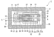
- FIG. 2 is an internal configuration diagram of the piezoelectric vibrator shown in FIG. 1, and is a view of the piezoelectric vibrator as viewed from above with the lid substrate removed.
- FIG. 3 is a cross-sectional view of the piezoelectric vibrator taken along line AA shown in FIG.
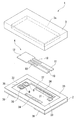
- FIG. 4 is an exploded perspective view of the piezoelectric vibrator shown in FIG.
- FIG. 5 is a top view of the piezoelectric vibrating piece constituting the piezoelectric vibrator shown in FIG. 6 is a bottom view of the piezoelectric vibrating piece shown in FIG. 7 is a cross-sectional view taken along the line BB shown in FIG. FIG.
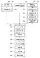
- FIG. 8 is a flowchart showing a flow of manufacturing the piezoelectric vibrator shown in FIG.
- FIG. 9 is a diagram showing one step in manufacturing the piezoelectric vibrator according to the flowchart shown in FIG. 8, in which a plurality of recesses and bonding films are formed on the lid substrate wafer that is the base of the lid substrate.
- FIG. 10 is a diagram showing one process in manufacturing a piezoelectric vibrator according to the flowchart shown in FIG. 8, in which a getter material, a through electrode, a lead-out electrode, and a bond are formed on a base substrate wafer that is a base substrate. It is a figure which shows the state in which the film
- FIG. 10 is a diagram showing one process in manufacturing a piezoelectric vibrator according to the flowchart shown in FIG. 8, in which a getter material, a through electrode, a lead-out electrode, and a bond are formed on a base substrate wafer that is a base substrate. It
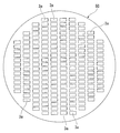
- FIG. 11 is an overall view of the base substrate wafer in the state shown in FIG.
- FIG. 12 is a diagram showing one process when the piezoelectric vibrator is manufactured according to the flowchart shown in FIG. 8, and the base substrate wafer, the lid substrate wafer, It is a disassembled perspective view of the wafer body by which anodic bonding was carried out.
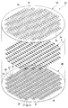
- FIG. 13 is a diagram showing a step in manufacturing the piezoelectric vibrator according to the flowchart shown in FIG. 8, and shows a state in which the getter material on the proximal end side of the vibrating arm portion is heated and evaporated. It is.
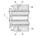
- FIG. 14 is an enlarged view of a portion E in FIG.
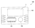
- FIG. 15 is a configuration diagram showing an embodiment of an oscillator according to the present invention.
- FIG. 16 is a configuration diagram showing an embodiment of an electronic apparatus according to the invention.
- FIG. 17 is a block diagram showing an embodiment of a radio timepiece according to the present invention.
- FIG. 18 is a plan view of a state in which a lid substrate of a piezoelectric vibrator according to the prior art is removed.
- FIG. 19 is a cross-sectional view taken along the line DD of FIG.
- Piezoelectric vibrator 2 Base substrate (package) 3 Lid board (package) 4 Piezoelectric vibrating piece 10 Vibrating arm portion 11 Vibrating arm portion 34 Getter material (adjustment film) 40 Base substrate wafer (package) 41 Laser irradiation trace (irradiation trace) 50 Lid substrate wafer (package) DESCRIPTION OF SYMBOLS 100 Oscillator 101 Oscillator integrated circuit 110 Portable information device (electronic device) 113 Timekeeping Unit of Electronic Equipment 130 Radio Clock 131 Radio Frequency Filter Filter L Center shaft
- the piezoelectric vibrator 1 is formed in a box shape in which a base substrate 2 and a lid substrate 3 are laminated in two layers, and the piezoelectric vibrating reed 4 is placed in an internal cavity C.
- This is a housed surface mount type piezoelectric vibrator.
- the excitation electrode 15, the extraction electrodes 19 and 20, the mount electrodes 16 and 17, and the weight metal film 21, which will be described later, are omitted for easy understanding of the drawing.
- the piezoelectric vibrating piece 4 is a tuning fork type vibrating piece formed from a piezoelectric material such as quartz crystal, lithium tantalate or lithium niobate, and when a predetermined voltage is applied. It vibrates.
- the piezoelectric vibrating reed 4 includes a pair of vibrating arm portions 10 and 11 arranged in parallel, a base portion 12 that integrally fixes the base end sides of the pair of vibrating arm portions 10 and 11, and a pair of vibrating arm portions.
- the piezoelectric vibrating reed 4 of the present embodiment includes groove portions 18 formed on both main surfaces of the pair of vibrating arm portions 10 and 11 along the longitudinal direction of the vibrating arm portions 10 and 11, respectively. .
- the groove portion 18 is formed from the proximal end side of the vibrating arm portions 10 and 11 to the vicinity of the middle.
- the excitation electrode 15 including the first excitation electrode 13 and the second excitation electrode 14 is an electrode that vibrates the pair of vibrating arm portions 10 and 11 at a predetermined resonance frequency in a direction approaching or separating from each other. Patterned on the outer surfaces of the vibrating arm portions 10 and 11 while being electrically separated from each other. Specifically, as shown in FIG. 7, the first excitation electrode 13 is mainly formed on the groove portion 18 of one vibration arm portion 10 and on both side surfaces of the other vibration arm portion 11. The excitation electrode 14 is mainly formed on both side surfaces of one vibration arm portion 10 and on the groove portion 18 of the other vibration arm portion 11.
- the first excitation electrode 13 and the second excitation electrode 14 are mounted on the main surfaces of the base portion 12 via the extraction electrodes 19 and 20, respectively, on the main electrodes 12 and 17. Is electrically connected. A voltage is applied to the piezoelectric vibrating reed 4 via the mount electrodes 16 and 17.
- the excitation electrode 15, the mount electrodes 16 and 17, and the extraction electrodes 19 and 20 described above are made of a conductive film such as chromium (Cr), nickel (Ni), aluminum (Al), or titanium (Ti). It is formed.
- a weight metal film 21 is coated on the tip side of the pair of vibrating arm portions 10 and 11 in order to adjust (frequency adjustment) the vibration state of itself within a predetermined frequency range. Yes.
- the weight metal film 21 is divided into a coarse adjustment film 21a used when the frequency is roughly adjusted and a fine adjustment film 21b used when the frequency is finely adjusted. By adjusting the frequency using the coarse adjustment film 21a and the fine adjustment film 21b, the frequency of the pair of vibrating arm portions 10 and 11 can be kept within the range of the nominal frequency of the device.
- the piezoelectric vibrating reed 4 configured as described above is bump-bonded to the upper surface of the base substrate 2 using bumps B such as gold as shown in FIGS. More specifically, bump bonding is performed with a pair of mount electrodes 16 and 17 in contact with two bumps B formed on routing electrodes 36 and 37 (described later) patterned on the upper surface of the base substrate 2. ing. As a result, the piezoelectric vibrating reed 4 is supported in a state of floating from the upper surface of the base substrate 2 and the mount electrodes 16 and 17 and the routing electrodes 36 and 37 are electrically connected to each other. Note that the bonding method of the piezoelectric vibrating reed 4 is not limited to bump bonding.
- the piezoelectric vibrating reed 4 may be joined with a conductive adhesive.
- the piezoelectric vibrating reed 4 can be lifted from the upper surface of the base substrate 2, and a minimum vibration gap necessary for vibration can be secured naturally. Therefore, it is preferable to perform bump bonding.
- the lid substrate 3 is a transparent insulating substrate made of a glass material, for example, soda-lime glass, and is formed in a plate shape as shown in FIGS.
- a rectangular recess 3 a in which the piezoelectric vibrating reed 4 is accommodated is formed on the bonding surface side to which the base substrate 2 is bonded.
- the recess 3 a is a cavity recess that serves as a cavity C that accommodates the piezoelectric vibrating reed 4 when the substrates 2 and 3 are overlapped.
- the lid substrate 3 is anodically bonded to the base substrate 2 with the recess 3a facing the base substrate 2 side. Note that the method of bonding the base substrate 2 and the lid substrate 3 is not limited to anodic bonding. However, anodic bonding is preferable because both substrates 2 and 3 can be firmly bonded.
- the base substrate 2 is a transparent insulating substrate made of a glass material, for example, soda lime glass, like the lid substrate 3, and has a size that can be superimposed on the lid substrate 3 as shown in FIGS. It is formed in a plate shape.
- the base substrate 2 is formed with a pair of through holes 30 and 31 penetrating the base substrate 2. At this time, the pair of through holes 30 and 31 are formed so as to be accommodated in the cavity C. More specifically, in the through holes 30 and 31 of the present embodiment, one through hole 30 is located on the base 12 side of the mounted piezoelectric vibrating reed 4, and the other through hole is on the tip side of the vibrating arm portions 10 and 11. It is formed so that the hole 31 is located.
- the pair of through holes 30 and 31 are formed with a pair of through electrodes 32 and 33 formed so as to fill the through holes 30 and 31. As shown in FIG. 3, these through-electrodes 32 and 33 completely close the through-holes 30 and 31 to maintain airtightness in the cavity C, and also lead to external electrodes 38 and 39 to be described later and lead-out electrodes 36 and 37. It plays a role of conducting.
- the upper surface side of the base substrate 2 (the bonding surface side to which the lid substrate 3 is bonded) is irradiated with a laser to improve the degree of vacuum in the cavity C (adjustment).
- a film) 34, a bonding film 35 for anodic bonding, and a pair of routing electrodes 36 and 37 are patterned. Note that the bonding film 35 and the pair of routing electrodes 36 and 37 are formed of a conductive material (for example, aluminum).
- the getter material 34 extends from the proximal end side to the distal end side along the longitudinal direction of the vibrating arm portions 10 and 11 in a state adjacent to the vicinity of the pair of vibrating arm portions 10 and 11 when viewed in plan. Further, it is made of aluminum or the like. More specifically, the getter material 34 is disposed on the outer surface side of the pair of vibrating arm portions 10 and 11 and through the central axis L of the pair of vibrating arm portions 10 and 11 as shown in FIGS. Are formed in symmetrical positions.
- the bonding film 35 is formed along the periphery of the base substrate 2 so as to surround the periphery of the recess 3 a formed in the lid substrate 3.
- the pair of lead-out electrodes 36 and 37 electrically connect one of the through electrodes 32 and 33 of the pair of through electrodes 32 and 33 to one of the mount electrodes 16 of the piezoelectric vibrating reed 4 and the other through electrode. 33 and the other mount electrode 17 of the piezoelectric vibrating reed 4 are patterned so as to be electrically connected. More specifically, the one lead-out electrode 36 is formed directly above the one through electrode 32 so as to be positioned directly below the base 12 of the piezoelectric vibrating piece 4. The other routing electrode 37 is routed from the position adjacent to the one routing electrode 36 along the vibrating arm portions 10 and 11 to the distal end side of the vibrating arm portions 10 and 11, and then the other through electrode 33. It is formed so that it may be located just above.
- Bumps B are formed on the pair of routing electrodes 36 and 37, and the piezoelectric vibrating reed 4 is mounted using the bumps B.
- one mount electrode 16 of the piezoelectric vibrating reed 4 is electrically connected to one through electrode 32 through one routing electrode 36, and the other mount electrode 17 is passed through the other routing electrode 37 to the other penetration electrode.
- the electrode 33 is electrically connected.
- external electrodes 38 and 39 that are electrically connected to the pair of through electrodes 32 and 33 are formed on the lower surface of the base substrate 2. . That is, one external electrode 38 is electrically connected to the first excitation electrode 13 of the piezoelectric vibrating reed 4 via one through electrode 32 and one routing electrode 36. The other external electrode 39 is electrically connected to the second excitation electrode 14 of the piezoelectric vibrating reed 4 via the other through electrode 33 and the other routing electrode 37.
- a predetermined drive voltage is applied to the external electrodes 38 and 39 formed on the base substrate 2.
- a current can flow through the excitation electrode 15 including the first excitation electrode 13 and the second excitation electrode 14 of the piezoelectric vibrating reed 4, and is predetermined in a direction in which the pair of vibrating arm portions 10 and 11 are approached and separated.
- Can be vibrated at a frequency of The vibration of the pair of vibrating arm portions 10 and 11 can be used as a time source, a control signal timing source, a reference signal source, and the like.
- piezoelectric vibrator manufacturing method Next, a plurality of the piezoelectric vibrators 1 described above are manufactured at once using a base substrate wafer (base substrate) 40 and a lid substrate wafer (lid substrate) 50 with reference to the flowchart shown in FIG. The manufacturing method will be described below.
- a plurality of piezoelectric vibrators 1 are manufactured at a time using a wafer-like substrate, but the present invention is not limited to this. It is also possible to process only one product and manufacture only one at a time.
- the piezoelectric vibrating reed manufacturing step is performed to manufacture the piezoelectric vibrating reed 4 shown in FIGS. 5 to 7 (S10). Specifically, a quartz Lambert rough is first sliced at a predetermined angle to obtain a wafer having a constant thickness. Subsequently, the wafer is lapped and roughly processed, and then the work-affected layer is removed by etching, and then mirror polishing such as polishing is performed to obtain a wafer having a predetermined thickness.
- the wafer is patterned with the outer shape of the piezoelectric vibrating reed 4 by a photolithography technique, and a metal film is formed and patterned, so that the excitation electrode 15, Lead electrodes 19 and 20, mount electrodes 16 and 17, and weight metal film 21 are formed. Thereby, the some piezoelectric vibrating piece 4 is producible.
- the resonance frequency is coarsely adjusted. This is done by irradiating the coarse adjustment film 21a of the weight metal film 21 with laser light to evaporate a part thereof and changing the weight. Note that fine adjustment for adjusting the resonance frequency with higher accuracy is performed after mounting. This will be described later.
- a first wafer manufacturing process is performed in which a lid substrate wafer 50 to be the lid substrate 3 later is manufactured up to a state immediately before anodic bonding (S20).
- a disk-shaped lid substrate wafer 50 is formed by removing the outermost work-affected layer by etching or the like (S21).
- a recess forming step is performed in which a plurality of cavity recesses 3a are formed in the matrix direction by etching or the like on the bonding surface of the lid substrate wafer 50 (S22). At this point, the first wafer manufacturing process is completed.
- a second wafer manufacturing process is performed in which the base substrate wafer 40 to be the base substrate 2 is manufactured up to the state immediately before anodic bonding (S30).
- a disk-shaped base substrate wafer 40 is formed by removing the outermost work-affected layer by etching or the like (S31).
- a through electrode forming step of forming a plurality of pairs of through electrodes 32 and 33 on the base substrate wafer 40 is performed (S32). Specifically, first, a plurality of a pair of through holes 30 and 31 are formed by a method such as sandblasting or press working. A pair of through electrodes 32 and 33 are formed in the plurality of pairs of through holes 30 and 31. The pair of through-holes 32 and 33 seals the pair of through holes 30 and 31 and ensures electrical conductivity between the upper surface side and the lower surface side of the base substrate wafer 40.
- the getter material 34 extends from the proximal end side to the distal end side along the longitudinal direction of the vibrating arm portions 10 and 11 in a state adjacent to the vicinity of the pair of vibrating arm portions 10 and 11 when viewed in plan. And formed on the outer surface side of the pair of vibrating arm portions 10 and 11 and at symmetrical positions via the central axis L (see FIG. 2) of the pair of vibrating arm portions 10 and 11.
- a conductive material is patterned on the upper surface of the base substrate wafer 40 to perform a bonding film forming step of forming the bonding film 35 (S34), and each pair of through electrodes
- the dotted line M shown in FIG.10 and FIG.11 has shown the cutting line cut
- the adjustment film formation step (S33), the bonding film formation step (S34), and the lead-out electrode formation step (S35) are in the process order.
- the order is not limited, and all the processes may be performed simultaneously. I do not care. Regardless of the order of steps, the same effects can be obtained. Therefore, the process order may be changed as necessary.
- a bonding process for bonding the base substrate wafer 40 and the lid substrate wafer 50 is performed (S40). This bonding process will be described in detail.
- a mounting process is performed in which the produced plurality of piezoelectric vibrating reeds 4 are bonded to the upper surface of the base substrate wafer 40 via the routing electrodes 36 and 37, respectively (S41).
- bumps B such as gold are formed on the pair of lead-out electrodes 36 and 37, respectively.
- the piezoelectric vibrating piece 4 is pressed against the bump B while heating the bump B to a predetermined temperature.
- the piezoelectric vibrating reed 4 is mechanically supported by the bumps B, and the mount electrodes 16 and 17 and the routing electrodes 36 and 37 are electrically connected. Therefore, at this time, the pair of excitation electrodes 15 of the piezoelectric vibrating reed 4 are in a conductive state with respect to the pair of through electrodes 32 and 33, respectively. Since the piezoelectric vibrating reed 4 is bump-bonded, it is supported in a state where it floats from the upper surface of the base substrate wafer 40.
- an overlaying process for overlaying the lid substrate wafer 50 on the base substrate wafer 40 is performed (S42). Specifically, both wafers 40 and 50 are aligned at the correct positions while using a reference mark (not shown) as an index. As a result, the mounted piezoelectric vibrating reed 4 is housed in a cavity C surrounded by the recess 3 a formed in the base substrate wafer 40 and the wafers 40 and 50.
- the two superposed wafers 40 and 50 are put into an anodic bonding apparatus (not shown), and a predetermined voltage is applied in a predetermined temperature atmosphere to perform anodic bonding (S43). Specifically, a predetermined voltage is applied between the bonding film 35 and the lid substrate wafer 50. As a result, an electrochemical reaction occurs at the interface between the bonding film 35 and the lid substrate wafer 50, and the two are firmly bonded and anodically bonded. Thereby, the piezoelectric vibrating reed 4 can be sealed in the cavity C, and the wafer body 60 shown in FIG. 12 in which the base substrate wafer 40 and the lid substrate wafer 50 are bonded can be obtained. In FIG.
- a conductive material is patterned on the lower surface of the base substrate wafer 40, and a pair of external electrodes 38 and 39 electrically connected to the pair of through electrodes 32 and 33, respectively.
- a plurality of external electrode forming steps are performed (S50). Through this step, the piezoelectric vibrating reed 4 sealed in the cavity C can be operated using the external electrodes 38 and 39.
- the getter material 34 is irradiated with laser light to evaporate, and the degree of vacuum in the cavity C is kept at a certain level.
- the gettering process adjusted as described above is performed (S60).
- a certain level means a state in which the series resonance resistance value does not vary greatly even if the degree of vacuum is further improved. Thereby, an appropriate series resonance resistance value can be ensured.
- the piezoelectric vibrating reed 4 is vibrated by applying a voltage to a pair of external electrodes 38 and 39 formed on the lower surface of the base substrate wafer 40. Then, laser light is irradiated through the base substrate wafer 40 (from the side on which the external electrodes 38 and 39 are formed) while measuring the series resonance resistance value, and the getter material 34 is heated and evaporated. Thereby, an appropriate series resonance resistance value can be ensured.
- the base substrate wafer 40 is moved in a state where the laser light source device is fixed, and the desired position of the getter material 34 is irradiated with the laser light.
- the getter material 34 is used to adjust the frequency within the approximate range near the target value while measuring the frequency.
- the method for adjusting the frequency during the gettering step will be described.
- the getter material 34 is arranged on the outer surface side of the pair of vibrating arm portions 10 and 11 when viewed in plan, and the pair of vibrating arm portions 10 and 10. 11 are formed at symmetrical positions via a central axis L (see FIG. 2). Therefore, when the getter material 34 is heated and evaporated, the getter material 34 is locally deposited on the side surfaces of the vibrating arm portions 10 and 11 located near the heating position.
- the frequency tends to increase if the position where the getter material 34 is deposited is on the proximal end side of the vibrating arm portions 10 and 11, and the frequency tends to decrease if the position is on the distal end side. Therefore, the frequency can be increased or decreased by changing the heating position of the getter material 34. Therefore, by determining the heating position of the getter material 34 according to the difference between the approximate range and the actually measured frequency, and locally evaporating the getter material 34 evaporated on the side surfaces of the vibrating arm portions 10 and 11, The vibration characteristics of the vibrating arm portions 10 and 11 can be changed. That is, simultaneously with the gettering, the frequencies of the pair of vibrating arm portions 10 and 11 can be adjusted within an approximate range near the target value.
- the getter material 34 on the base end side of the pair of vibrating arm portions 10 and 11 (for example, the range indicated by the one-dot chain line in FIG. 13) is heated. That's fine. Thereby, a frequency can be raised and a frequency can be brought close to an approximate range.
- an appropriate series resonance resistance value can be secured, and the frequency can be driven in advance so as to be within the approximate range. Note that the degree of vacuum in the cavity C is not affected by the heating position of the getter material 34.
- the getter material 34 when the getter material 34 is irradiated with laser light, a pair of getter materials 34 and 34 formed to correspond to the pair of vibrating arm portions 10 and 11 respectively,
- the laser beam is irradiated to a symmetrical position via the central axis L of the vibrating arm portions 10 and 11.
- a laser irradiation mark 41 remains on the getter material 34, the getter material 34 in that portion evaporates, and the pair of vibrating arm portions 10, 11 is vapor-deposited on the outer side surfaces 10a and 11a.
- the position and amount of the getter material 34 deposited on the side surfaces 10a and 11a can be made substantially uniform by irradiating the laser beam to a symmetrical position via the central axis L. Therefore, the piezoelectric vibrator 1 formed in this way can obtain stable vibration characteristics and can reduce vibration leakage.
- the frequency of the piezoelectric vibrating piece 4 can be finely adjusted so as to be within a predetermined range of the nominal frequency.
- a cutting process is performed in which the bonded wafer body 60 is cut along the cutting line M shown in FIG.
- the piezoelectric vibration piece 4 is sealed in the cavity C formed between the base substrate 2 and the lid substrate 3 that are anodically bonded to each other, and the two-layer structure surface mount type piezoelectric vibration shown in FIG. A plurality of children 1 can be manufactured at a time.
- the order of the gettering step (S60) and the fine adjustment step (S70) may be performed.
- fine adjustment can be performed in the state of the wafer body 60, so that the plurality of piezoelectric vibrators 1 can be made more efficient. Can be fine tuned. Therefore, it is preferable because throughput can be improved.
- an internal electrical characteristic inspection is performed (S90). That is, the resonance frequency, resonance resistance value, drive level characteristic (excitation power dependency of the resonance frequency and resonance resistance value) and the like of the piezoelectric vibrating piece 4 are measured and checked. In addition, the insulation resistance characteristics and the like are also checked. Finally, an appearance inspection of the piezoelectric vibrator 1 is performed to finally check dimensions, quality, and the like. This completes the manufacture of the piezoelectric vibrator 1.
- a pair of getter materials 34, 34 are irradiated with laser light at symmetrical positions via the central axis L to evaporate a part of the getter material 34.
- the getter material 34 deposited on the side surfaces 10a and 11a of the vibrating arm portions 10 and 11 can be made substantially uniform.
- the vibration characteristics of the vibrating arms 10 and 11 change depending on the gettering position in the longitudinal direction of the vibrating arms 10 and 11, a pair of vibrating arms is obtained by gettering to a symmetrical position via the central axis L.
- the vibration characteristics of 10 and 11 can be matched. Therefore, stable vibration characteristics can be obtained even after the gettering step, and vibration leakage can be reduced. As a result, the yield can be improved.
- the oscillator 100 is configured such that the piezoelectric vibrator 1 is an oscillator electrically connected to the integrated circuit 101.
- the oscillator 100 includes a substrate 103 on which an electronic component 102 such as a capacitor is mounted. On the substrate 103, the integrated circuit 101 for the oscillator is mounted, and the piezoelectric vibrator 1 is mounted in the vicinity of the integrated circuit 101.
- the electronic component 102, the integrated circuit 101, and the piezoelectric vibrator 1 are electrically connected by a wiring pattern (not shown). Each component is molded with a resin (not shown).
- the piezoelectric vibrating reed 4 in the piezoelectric vibrator 1 vibrates. This vibration is converted into an electric signal by the piezoelectric characteristics of the piezoelectric vibrating piece 4 and input to the integrated circuit 101 as an electric signal.
- the input electrical signal is subjected to various processes by the integrated circuit 101 and is output as a frequency signal.
- the piezoelectric vibrator 1 functions as an oscillator.
- an RTC real-time clock
- a function for controlling the time, providing a time, a calendar, and the like can be added.
- the quality is improved by finely adjusting the frequency with higher accuracy while reducing the load accumulation due to heating, and the gettering and fine adjustment are efficiently performed. Since the piezoelectric vibrator 1 having stable vibration characteristics is provided, the oscillator 100 itself can improve the operation reliability and improve the quality. In addition to this, it is possible to obtain a highly accurate frequency signal that is stable over a long period of time.
- a portable information device 110 having the above-described piezoelectric vibrator 1 will be described as an example of the electronic device.
- the portable information device 110 of the present embodiment is represented by, for example, a mobile phone, and is a development and improvement of a wrist watch in the prior art. The appearance is similar to that of a wristwatch, and a liquid crystal display is arranged in a portion corresponding to a dial so that the current time and the like can be displayed on this screen.
- the portable information device 110 includes the piezoelectric vibrator 1 and a power supply unit 111 for supplying power.
- the power supply unit 111 is made of, for example, a lithium secondary battery.
- the power supply unit 111 includes a control unit 112 that performs various controls, a clock unit 113 that counts time, a communication unit 114 that communicates with the outside, a display unit 115 that displays various types of information, A voltage detection unit 116 that detects the voltage of the functional unit is connected in parallel.
- the power unit 111 supplies power to each functional unit.
- the control unit 112 controls each function unit to control operation of the entire system such as transmission and reception of voice data, measurement and display of the current time, and the like.
- the control unit 112 includes a ROM in which a program is written in advance, a CPU that reads and executes the program written in the ROM, and a RAM that is used as a work area for the CPU.
- the clock unit 113 includes an integrated circuit including an oscillation circuit, a register circuit, a counter circuit, an interface circuit, and the like, and the piezoelectric vibrator 1.
- the piezoelectric vibrator 1 When a voltage is applied to the piezoelectric vibrator 1, the piezoelectric vibrating reed 4 vibrates, and the vibration is converted into an electric signal by the piezoelectric characteristics of the crystal and is input to the oscillation circuit as an electric signal.
- the output of the oscillation circuit is binarized and counted by a register circuit and a counter circuit. Then, signals are transmitted to and received from the control unit 112 via the interface circuit, and the current time, current date, calendar information, or the like is displayed on the display unit 115.
- the communication unit 114 has functions similar to those of a conventional mobile phone, and includes a radio unit 117, a voice processing unit 118, a switching unit 119, an amplification unit 120, a voice input / output unit 121, a telephone number input unit 122, and a ring tone generation unit. 123 and a call control memory unit 124.
- the wireless unit 117 exchanges various data such as audio data with the base station via the antenna 125.
- the audio processing unit 118 encodes and decodes the audio signal input from the radio unit 117 or the amplification unit 120.
- the amplifying unit 120 amplifies the signal input from the audio processing unit 118 or the audio input / output unit 121 to a predetermined level.
- the voice input / output unit 121 includes a speaker, a microphone, and the like, and amplifies a ringtone and a received voice or collects a voice.
- the ring tone generator 123 generates a ring tone in response to a call from the base station.
- the switching unit 119 switches the amplifying unit 120 connected to the voice processing unit 118 to the ringing tone generating unit 123 only when an incoming call is received, so that the ringing tone generated in the ringing tone generating unit 123 is transmitted via the amplifying unit 120.
- the call control memory unit 124 stores a program related to incoming / outgoing call control of communication.
- the telephone number input unit 122 includes, for example, a number key from 0 to 9 and other keys. By pressing these number keys and the like, a telephone number of a call destination is input.
- the voltage detection unit 116 detects the voltage drop and notifies the control unit 112 of the voltage drop.
- the predetermined voltage value at this time is a value set in advance as a minimum voltage necessary for stably operating the communication unit 114, and is, for example, about 3V.
- the control unit 112 prohibits the operations of the radio unit 117, the voice processing unit 118, the switching unit 119, and the ring tone generation unit 123. In particular, it is essential to stop the operation of the wireless unit 117 with high power consumption. Further, the display unit 115 displays that the communication unit 114 has become unusable due to insufficient battery power.
- the operation of the communication unit 114 can be prohibited by the voltage detection unit 116 and the control unit 112, and that effect can be displayed on the display unit 115.
- This display may be a text message, but as a more intuitive display, a x (X) mark may be attached to the telephone icon displayed at the top of the display surface of the display unit 115.
- the function of the communication part 114 can be stopped more reliably by providing the power supply cutoff part 126 that can selectively cut off the power of the part related to the function of the communication part 114.
- the quality is improved by finely adjusting the frequency with higher accuracy while reducing the accumulation of load due to heating, and gettering and fine adjustment are performed. Since the piezoelectric vibrator 1 having stable vibration characteristics is provided by performing efficiently, the portable information device 110 itself can similarly improve the reliability of operation and improve the quality. In addition to this, it is possible to display highly accurate clock information that is stable over a long period of time.
- the radio timepiece 130 of this embodiment includes the piezoelectric vibrator 1 that is electrically connected to the filter unit 131.
- the radio timepiece 130 receives a standard radio wave including timepiece information and is accurate. It is a clock with a function of automatically correcting and displaying the correct time.
- transmitting stations that transmit standard radio waves in Fukushima Prefecture (40 kHz) and Saga Prefecture (60 kHz), each transmitting standard radio waves.
- Long waves such as 40 kHz or 60 kHz have the property of propagating the surface of the earth and the property of propagating while reflecting the ionosphere and the surface of the earth, so the propagation range is wide, and the above two transmitting stations cover all of Japan. is doing.
- the antenna 132 receives a long standard wave of 40 kHz or 60 kHz.
- the long-wave standard radio wave is obtained by subjecting time information called a time code to AM modulation on a 40 kHz or 60 kHz carrier wave.
- the received long standard wave is amplified by the amplifier 133 and filtered and tuned by the filter unit 131 having the plurality of piezoelectric vibrators 1.
- the piezoelectric vibrator 1 according to this embodiment includes crystal vibrator portions 138 and 139 having resonance frequencies of 40 kHz and 60 kHz that are the same as the carrier frequency.
- the filtered signal having a predetermined frequency is detected and demodulated by the detection and rectification circuit 134. Subsequently, the time code is taken out via the waveform shaping circuit 135 and counted by the CPU 136.
- the CPU 136 reads information such as the current year, accumulated date, day of the week, and time. The read information is reflected in the RTC 137, and accurate time information is displayed. Since the carrier wave is 40 kHz or 60 kHz, the crystal vibrator units 138 and 139 are preferably vibrators having the tuning fork type structure described above.
- the frequency of the long standard radio wave is different overseas.
- a standard radio wave of 77.5 KHz is used. Therefore, when the radio timepiece 130 that can be used overseas is incorporated in a portable device, the piezoelectric vibrator 1 having a frequency different from that in Japan is required.
- the quality is improved by finely adjusting the frequency with higher accuracy while reducing load accumulation due to heating, and the gettering and fine adjustment are efficiently performed. Since the piezoelectric vibrator 1 having stable vibration characteristics is provided by performing it frequently, the radio-controlled timepiece 130 itself can improve the reliability of operation and improve the quality. In addition to this, it is possible to count time stably and with high accuracy over a long period of time.
- the piezoelectric vibrator 1 is the surface mount type piezoelectric vibrator 1 of the two-layer structure type, but is not limited thereto, and may be a piezoelectric vibrator of the three-layer structure type. That is, a piezoelectric vibrator plate having a frame-like portion surrounding the piezoelectric vibrating piece 4 is used, the piezoelectric vibrator plate is mounted on the upper surface of the base substrate 2, and then the base substrate 2 and the lid substrate 3 are attached to the piezoelectric substrate.
- a piezoelectric vibrator may be formed by bonding via a vibrator plate and sealing the piezoelectric vibrating piece 4 in the cavity.
- the fine adjustment process is performed by forming the fine adjustment film 21b as the weight metal film 21 and heating the fine adjustment film 21b.
- the excitation electrode 15 is formed on the tip side of the pair of vibrating arms 10 and 11 so as to extend to the vicinity of the coarse adjustment film 21a, and a part of the excitation electrode 15 is heated to perform a fine adjustment step. It doesn't matter. That is, in this case, a part of the excitation electrode 15 functions as the weight metal film 21.
- the getter material 34 is formed on the base substrate 2 as an example.
- the getter material 34 may be formed on at least one of the base substrate 2 and the lid substrate 3. That is, it may be formed on the lid substrate 3 or may be formed on both the substrates 2 and 3.
- the grooved piezoelectric vibrating piece 4 in which the groove portions 18 are formed on both surfaces of the vibrating arm portions 10 and 11 has been described as an example.
- the piezoelectric vibrating piece may be used.
- the groove portion 18 when a predetermined voltage is applied to the pair of excitation electrodes 15, the electric field efficiency between the pair of excitation electrodes 15 can be increased. Can be further improved. That is, the CI value (Crystal Impedance) can be further lowered, and the piezoelectric vibrating piece 4 can be further improved in performance. In this respect, it is preferable to form the groove 18.
- the pair of through electrodes 33 and 34 is formed, but the present invention is not limited to this.
- the piezoelectric vibrator 1 is manufactured using a wafer, by forming the through electrodes 33 and 34, the individual piezoelectric vibrating reeds 4 can be vibrated in a wafer shape.
- a gettering process and a fine tuning process can be performed. Therefore, it is preferable to form the through electrodes 33 and 34.
- the piezoelectric vibrating reed 4 is bump-bonded.
- the present invention is not limited to bump bonding.
- the piezoelectric vibrating reed 4 may be joined with a conductive adhesive.
- the piezoelectric vibrating reed 4 can be lifted from the upper surface of the base substrate 2, and a minimum vibration gap necessary for vibration can be secured naturally. Therefore, it is preferable to perform bump bonding.
- the base substrate wafer 40 is moved while the laser light source device is fixed, and laser light is irradiated to a desired position of the getter material 34.
- the getter material 34 may be irradiated with laser light while the wafer 40 is fixed and the laser light source device is moved.
- the method for manufacturing a piezoelectric vibrator according to the present invention can be applied to a surface mount type (SMD) piezoelectric vibrator in which a piezoelectric vibrating piece is sealed in a cavity formed between two bonded substrates.
- SMD surface mount type
Landscapes
- Physics & Mathematics (AREA)
- Acoustics & Sound (AREA)
- Chemical & Material Sciences (AREA)
- Crystallography & Structural Chemistry (AREA)
- Engineering & Computer Science (AREA)
- Manufacturing & Machinery (AREA)
- Piezo-Electric Or Mechanical Vibrators, Or Delay Or Filter Circuits (AREA)
Abstract
Description
等価抵抗値を抑えるための一般的な方法の一つとして、図18に示すように圧電振動片203の封止されているキャビティC内を真空に近づけて、等価抵抗値と比例関係にある直列共振抵抗値(R1)を低下させる方法が知られている。キャビティC内を真空に近づける方法として、キャビティC内にアルミニウムなどのゲッター材220を封止し、外部よりレーザを照射してゲッター材220を活性化させる方法(ゲッタリング)が知られている(例えば、特許文献1および2参照)。この方法によれば、活性化状態になったゲッター材220によって、陽極接合の際に発生する酸素を吸収することができるため、キャビティC内を真空に近づけることができる。
本発明に係る圧電振動子の製造方法は、一対の振動腕部を備えた音叉型の圧電振動片と、前記圧電振動片を収容するパッケージと、前記一対の振動腕部のそれぞれに対応して、前記振動腕部の長手方向に沿って形成された一対の調整膜と、を備え、前記調整膜にレーザを照射して前記調整膜の一部を蒸発させることにより前記パッケージ内の真空度を一定レベル以上に調整することが可能な圧電振動子の製造方法において、前記一対の調整膜における前記一対の振動腕部の中心軸を介して対称な位置に前記レーザを照射するゲッタリング工程を有することを特徴としている。
さらに、本発明に係る電子機器は、上述した圧電振動子が、計時部に電気的に接続されていることを特徴としている。
そして、本発明に係る電波時計は、上述した圧電振動子が、フィルタ部に電気的に接続されていることを特徴としている。
2 ベース基板(パッケージ)
3 リッド基板(パッケージ)
4 圧電振動片
10 振動腕部
11 振動腕部
34 ゲッター材(調整膜)
40 ベース基板用ウエハ(パッケージ)
41 レーザ照射痕(照射痕)
50 リッド基板用ウエハ(パッケージ)
100 発振器
101 発振器の集積回路
110 携帯情報機器(電子機器)
113 電子機器の計時部
130 電波時計
131 電波時計のフィルタ部
L 中心軸
図1~図4に示すように、圧電振動子1は、ベース基板2とリッド基板3とで2層に積層された箱状に形成されており、内部のキャビティC内に圧電振動片4が収容された表面実装型の圧電振動子である。なお、図4においては、図面を見易くするために後述する励振電極15、引き出し電極19、20、マウント電極16、17、重り金属膜21の図示を省略している。
次に、上述した圧電振動子1を、図8に示すフローチャートを参照しながら、ベース基板用ウエハ(ベース基板)40とリッド基板用ウエハ(リッド基板)50とを利用して一度に複数製造する製造方法について以下に説明する。なお、本実施形態では、ウエハ状の基板を利用して圧電振動子1を一度に複数製造するが、これに限られたものではなく、予めベース基板2及びリッド基板3の外形に寸法を合わせたものを加工して、一度に一つのみ製造する等しても構わない。
次に、本発明に係る発振器の一実施形態について、図15を用いて説明する。
本実施形態の発振器100は、図15に示すように、圧電振動子1を、集積回路101に電気的に接続された発振子として構成したものである。この発振器100は、コンデンサ等の電子部品102が実装された基板103を備えている。基板103には、発振器用の上記集積回路101が実装されており、この集積回路101の近傍に、圧電振動子1が実装されている。これら電子部品102、集積回路101及び圧電振動子1は、図示しない配線パターンによってそれぞれ電気的に接続されている。なお、各構成部品は、図示しない樹脂によりモールドされている。
また、集積回路101の構成を、例えば、RTC(リアルタイムクロック)モジュール等を要求に応じて選択的に設定することで、時計用単機能発振器等の他、当該機器や外部機器の動作日や時刻を制御したり、時刻やカレンダー等を提供したりする機能を付加することができる。
次に、本発明に係る電子機器の一実施形態について、図16を用いて説明する。なお、電子機器として、上述した圧電振動子1を有する携帯情報機器110を例にして説明する。本実施形態の携帯情報機器110は、例えば、携帯電話に代表されるものであり、従来技術における腕時計を発展、改良したものである。外観は腕時計に類似し、文字盤に相当する部分に液晶ディスプレイを配し、この画面上に現在の時刻等を表示させることができるものである。また、通信機として利用する場合には、手首から外し、バンドの内側部分に内蔵されたスピーカ及びマイクロフォンによって、従来技術の携帯電話と同様の通信を行うことが可能である。しかしながら、従来の携帯電話と比較して、格段に小型化及び軽量化されている。
無線部117は、音声データ等の各種データを、アンテナ125を介して基地局と送受信のやりとりを行う。音声処理部118は、無線部117又は増幅部120から入力された音声信号を符号化及び複号化する。増幅部120は、音声処理部118又は音声入出力部121から入力された信号を、所定のレベルまで増幅する。音声入出力部121は、スピーカやマイクロフォン等からなり、着信音や受話音声を拡声したり、音声を集音したりする。
次に、本発明に係る電波時計の一実施形態について、図17を用いて説明する。
本実施形態の電波時計130は、図17に示すように、フィルタ部131に電気的に接続された圧電振動子1を備えたものであり、時計情報を含む標準の電波を受信して、正確な時刻に自動修正して表示する機能を備えた時計である。
アンテナ132は、40kHz若しくは60kHzの長波の標準電波を受信する。長波の標準電波は、タイムコードと呼ばれる時刻情報を、40kHz若しくは60kHzの搬送波にAM変調をかけたものである。受信された長波の標準電波は、アンプ133によって増幅され、複数の圧電振動子1を有するフィルタ部131によって濾波、同調される。本実施形態における圧電振動子1は、上記搬送周波数と同一の40kHz及び60kHzの共振周波数を有する水晶振動子部138、139をそれぞれ備えている。
Claims (5)
- 一対の振動腕部を備えた音叉型の圧電振動片と、
前記圧電振動片を収容するパッケージと、
前記一対の振動腕部のそれぞれに対応して、前記振動腕部の長手方向に沿って形成された一対の調整膜と、を備え、
前記調整膜にレーザを照射して前記調整膜の一部を蒸発させることにより前記パッケージ内の真空度を一定レベル以上に調整することが可能な圧電振動子の製造方法において、
前記一対の調整膜における前記一対の振動腕部の中心軸を介して対称な位置に前記レーザを照射するゲッタリング工程を有することを特徴とする圧電振動子の製造方法。 - 一対の振動腕部を備えた音叉型の圧電振動片と、
前記圧電振動片を収容するパッケージと、
前記一対の振動腕部のそれぞれに対応して、前記振動腕部の長手方向に沿って形成された一対の調整膜と、を備え、
前記調整膜にレーザを照射して前記調整膜の一部を蒸発させることにより前記パッケージ内の真空度を向上させることが可能な圧電振動子において、
前記一対の調整膜における前記一対の振動腕部の中心軸を介して対称な位置に前記レーザの照射痕が形成されていることを特徴とする圧電振動子。 - 請求項2に記載の圧電振動子が、発振子として集積回路に電気的に接続されていることを特徴とする発振器。
- 請求項2に記載の圧電振動子が、計時部に電気的に接続されていることを特徴とする電子機器。
- 請求項2に記載の圧電振動子が、フィルタ部に電気的に接続されていることを特徴とする電波時計。
Priority Applications (5)
| Application Number | Priority Date | Filing Date | Title |
|---|---|---|---|
| CN2008801318334A CN102197585A (zh) | 2008-08-27 | 2008-08-27 | 压电振动器的制造方法、压电振动器、振荡器、电子设备及电波钟 |
| JP2010526450A JP5121934B2 (ja) | 2008-08-27 | 2008-08-27 | 圧電振動子の製造方法、圧電振動子、発振器、電子機器および電波時計 |
| PCT/JP2008/065247 WO2010023728A1 (ja) | 2008-08-27 | 2008-08-27 | 圧電振動子の製造方法、圧電振動子、発振器、電子機器および電波時計 |
| TW098123914A TW201019597A (en) | 2008-08-27 | 2009-07-15 | Method for manufacturing piezoelectric vibrator, piezoelectric vibrator, oscillator, electronic apparatus, and wave clock |
| US13/035,519 US8633775B2 (en) | 2008-08-27 | 2011-02-25 | Method of manufacturing piezoelectric vibrator, piezoelectric vibrator, oscillator, electronic equipment and radio-controlled timepiece |
Applications Claiming Priority (1)
| Application Number | Priority Date | Filing Date | Title |
|---|---|---|---|
| PCT/JP2008/065247 WO2010023728A1 (ja) | 2008-08-27 | 2008-08-27 | 圧電振動子の製造方法、圧電振動子、発振器、電子機器および電波時計 |
Related Child Applications (1)
| Application Number | Title | Priority Date | Filing Date |
|---|---|---|---|
| US13/035,519 Continuation US8633775B2 (en) | 2008-08-27 | 2011-02-25 | Method of manufacturing piezoelectric vibrator, piezoelectric vibrator, oscillator, electronic equipment and radio-controlled timepiece |
Publications (1)
| Publication Number | Publication Date |
|---|---|
| WO2010023728A1 true WO2010023728A1 (ja) | 2010-03-04 |
Family
ID=41720917
Family Applications (1)
| Application Number | Title | Priority Date | Filing Date |
|---|---|---|---|
| PCT/JP2008/065247 Ceased WO2010023728A1 (ja) | 2008-08-27 | 2008-08-27 | 圧電振動子の製造方法、圧電振動子、発振器、電子機器および電波時計 |
Country Status (5)
| Country | Link |
|---|---|
| US (1) | US8633775B2 (ja) |
| JP (1) | JP5121934B2 (ja) |
| CN (1) | CN102197585A (ja) |
| TW (1) | TW201019597A (ja) |
| WO (1) | WO2010023728A1 (ja) |
Cited By (2)
| Publication number | Priority date | Publication date | Assignee | Title |
|---|---|---|---|---|
| US9628046B2 (en) | 2013-11-16 | 2017-04-18 | Seiko Epson Corporation | Resonator element, resonator, oscillator, electronic apparatus, and mobile object |
| JP2023021842A (ja) * | 2021-08-02 | 2023-02-14 | エスアイアイ・クリスタルテクノロジー株式会社 | 圧電振動片、圧電振動子および発振器 |
Families Citing this family (8)
| Publication number | Priority date | Publication date | Assignee | Title |
|---|---|---|---|---|
| CN102197586B (zh) * | 2008-08-27 | 2014-03-05 | 精工电子水晶科技股份有限公司 | 压电振动器、振荡器、电子设备、电波钟以及压电振动器的制造方法 |
| JP2013187852A (ja) * | 2012-03-09 | 2013-09-19 | Seiko Instruments Inc | 圧電振動子、発振器、電子機器、及び電波時計 |
| CN103682637B (zh) * | 2012-09-12 | 2018-05-11 | 深圳富泰宏精密工业有限公司 | 无线通信装置 |
| JP2014135655A (ja) * | 2013-01-10 | 2014-07-24 | Sii Crystal Technology Inc | 圧電振動片、圧電振動子、発振器、電子機器及び電波時計 |
| JP2014135654A (ja) * | 2013-01-10 | 2014-07-24 | Sii Crystal Technology Inc | 圧電振動片、圧電振動子、発振器、電子機器及び電波時計 |
| JP6154458B2 (ja) * | 2013-02-25 | 2017-06-28 | 京セラ株式会社 | 電子部品収納用パッケージおよび電子装置 |
| WO2017090380A1 (ja) * | 2015-11-24 | 2017-06-01 | 株式会社村田製作所 | 共振装置及びその製造方法 |
| JP6635605B2 (ja) * | 2017-10-11 | 2020-01-29 | 国立研究開発法人理化学研究所 | 電流導入端子並びにそれを備えた圧力保持装置及びx線撮像装置 |
Citations (3)
| Publication number | Priority date | Publication date | Assignee | Title |
|---|---|---|---|---|
| JPH0681132U (ja) * | 1993-04-13 | 1994-11-15 | シチズン時計株式会社 | 水晶振動子 |
| JP2003142976A (ja) * | 2001-10-31 | 2003-05-16 | Seiko Instruments Inc | 圧電振動子及びその製造方法 |
| JP2007251238A (ja) * | 2006-03-13 | 2007-09-27 | Epson Toyocom Corp | 圧電デバイスおよび圧電デバイスの製造方法 |
Family Cites Families (5)
| Publication number | Priority date | Publication date | Assignee | Title |
|---|---|---|---|---|
| US3766616A (en) * | 1972-03-22 | 1973-10-23 | Statek Corp | Microresonator packaging and tuning |
| US20050238803A1 (en) | 2003-11-12 | 2005-10-27 | Tremel James D | Method for adhering getter material to a surface for use in electronic devices |
| JP4696488B2 (ja) * | 2004-07-15 | 2011-06-08 | セイコーエプソン株式会社 | 圧電振動子の周波数調整方法および圧電振動子 |
| JP2006086585A (ja) | 2004-09-14 | 2006-03-30 | Daishinku Corp | 表面実装型圧電振動デバイス |
| WO2009072358A1 (ja) * | 2007-12-04 | 2009-06-11 | Seiko Instruments Inc. | 圧電振動子の製造方法、並びに圧電振動子、発振器、電子機器及び電波時計 |
-
2008
- 2008-08-27 WO PCT/JP2008/065247 patent/WO2010023728A1/ja not_active Ceased
- 2008-08-27 CN CN2008801318334A patent/CN102197585A/zh active Pending
- 2008-08-27 JP JP2010526450A patent/JP5121934B2/ja not_active Expired - Fee Related
-
2009
- 2009-07-15 TW TW098123914A patent/TW201019597A/zh unknown
-
2011
- 2011-02-25 US US13/035,519 patent/US8633775B2/en not_active Expired - Fee Related
Patent Citations (3)
| Publication number | Priority date | Publication date | Assignee | Title |
|---|---|---|---|---|
| JPH0681132U (ja) * | 1993-04-13 | 1994-11-15 | シチズン時計株式会社 | 水晶振動子 |
| JP2003142976A (ja) * | 2001-10-31 | 2003-05-16 | Seiko Instruments Inc | 圧電振動子及びその製造方法 |
| JP2007251238A (ja) * | 2006-03-13 | 2007-09-27 | Epson Toyocom Corp | 圧電デバイスおよび圧電デバイスの製造方法 |
Cited By (3)
| Publication number | Priority date | Publication date | Assignee | Title |
|---|---|---|---|---|
| US9628046B2 (en) | 2013-11-16 | 2017-04-18 | Seiko Epson Corporation | Resonator element, resonator, oscillator, electronic apparatus, and mobile object |
| JP2023021842A (ja) * | 2021-08-02 | 2023-02-14 | エスアイアイ・クリスタルテクノロジー株式会社 | 圧電振動片、圧電振動子および発振器 |
| JP7677849B2 (ja) | 2021-08-02 | 2025-05-15 | エスアイアイ・クリスタルテクノロジー株式会社 | 圧電振動片、圧電振動子および発振器 |
Also Published As
| Publication number | Publication date |
|---|---|
| CN102197585A (zh) | 2011-09-21 |
| US8633775B2 (en) | 2014-01-21 |
| TW201019597A (en) | 2010-05-16 |
| JPWO2010023728A1 (ja) | 2012-01-26 |
| US20110140795A1 (en) | 2011-06-16 |
| JP5121934B2 (ja) | 2013-01-16 |
Similar Documents
| Publication | Publication Date | Title |
|---|---|---|
| JP5237976B2 (ja) | 圧電振動子、圧電振動子の製造方法、発振器、電子機器及び電波時計 | |
| JP5121493B2 (ja) | 圧電振動子の製造方法 | |
| JP5121934B2 (ja) | 圧電振動子の製造方法、圧電振動子、発振器、電子機器および電波時計 | |
| JP5237965B2 (ja) | 圧電振動子の製造方法 | |
| JP5226791B2 (ja) | 圧電振動子、発振器、電子機器及び電波時計並びに圧電振動子の製造方法 | |
| WO2009081686A1 (ja) | 圧電振動子の製造方法、圧電振動子、発振器、電子機器及び電波時計 | |
| JP2011049665A (ja) | 圧電振動子、圧電振動子の製造方法、発振器、電子機器および電波時計 | |
| JP5226073B2 (ja) | 圧電振動子、発振器、電子機器および電波時計 | |
| JP5162675B2 (ja) | 圧電振動子の製造方法、並びに圧電振動子、発振器、電子機器及び電波時計 | |
| JP2011029910A (ja) | 圧電振動子、圧電振動子の製造方法、発振器、電子機器および電波時計 | |
| JP5128670B2 (ja) | 圧電振動子、発振器、電子機器及び電波時計、並びに圧電振動子の製造方法 | |
| JP2011030095A (ja) | 圧電振動子、圧電振動子の製造方法、発振器、電子機器および電波時計 | |
| US8898875B2 (en) | Method of manufacturing piezoelectric vibrators | |
| JP5128669B2 (ja) | 圧電振動子の製造方法 | |
| JP5184648B2 (ja) | 圧電振動子の製造方法 | |
| JP2011029911A (ja) | 圧電振動子の製造方法、並びに圧電振動子、発振器、電子機器および電波時計 | |
| JP5128671B2 (ja) | 圧電振動子、発振器、電子機器及び電波時計、並びに圧電振動子の製造方法 | |
| JP5421690B2 (ja) | パッケージの製造方法 | |
| JPWO2010097901A1 (ja) | 陽極接合方法、パッケージの製造方法、圧電振動子の製造方法、発振器、電子機器および電波時計 | |
| JP2012205257A (ja) | パッケージの製造方法、圧電振動子、発振器、電子機器及び電波時計 | |
| WO2010097900A1 (ja) | パッケージの製造方法、圧電振動子の製造方法、発振器、電子機器および電波時計 |
Legal Events
| Date | Code | Title | Description |
|---|---|---|---|
| WWE | Wipo information: entry into national phase |
Ref document number: 200880131833.4 Country of ref document: CN |
|
| 121 | Ep: the epo has been informed by wipo that ep was designated in this application |
Ref document number: 08809355 Country of ref document: EP Kind code of ref document: A1 |
|
| WWE | Wipo information: entry into national phase |
Ref document number: 2010526450 Country of ref document: JP |
|
| NENP | Non-entry into the national phase |
Ref country code: DE |
|
| 122 | Ep: pct application non-entry in european phase |
Ref document number: 08809355 Country of ref document: EP Kind code of ref document: A1 |