WO2010021284A1 - 口腔洗浄装置 - Google Patents
口腔洗浄装置 Download PDFInfo
- Publication number
- WO2010021284A1 WO2010021284A1 PCT/JP2009/064257 JP2009064257W WO2010021284A1 WO 2010021284 A1 WO2010021284 A1 WO 2010021284A1 JP 2009064257 W JP2009064257 W JP 2009064257W WO 2010021284 A1 WO2010021284 A1 WO 2010021284A1
- Authority
- WO
- WIPO (PCT)
- Prior art keywords
- water
- electrolyzed water
- electrolyzed
- storage tank
- tank
- Prior art date
- Legal status (The legal status is an assumption and is not a legal conclusion. Google has not performed a legal analysis and makes no representation as to the accuracy of the status listed.)
- Ceased
Links
Images






Classifications
-
- A—HUMAN NECESSITIES
- A61—MEDICAL OR VETERINARY SCIENCE; HYGIENE
- A61C—DENTISTRY; APPARATUS OR METHODS FOR ORAL OR DENTAL HYGIENE
- A61C17/00—Devices for cleaning, polishing, rinsing or drying teeth, teeth cavities or prostheses; Saliva removers; Dental appliances for receiving spittle
- A61C17/02—Rinsing or air-blowing devices, e.g. using fluid jets or comprising liquid medication
Definitions
- the present invention relates to an oral cleaning device for performing oral cleaning by injecting electrolyzed water into the oral cavity.
- Japanese Patent Publication No. 5-76550 and Japanese Patent Publication No. 10-33571 disclose an oral cleaning device that generates electrolytic water and injects it from a nozzle.
- Oral cleaning devices are often used after brushing teeth on a washstand or the like. Therefore, there is a demand for installing the oral cleaning device near a washstand or the like.
- the conventional oral cleaning device includes a second water storage tank for storing electrolytic water used for oral cleaning separately from the first water storage tank for storing water for generating electrolyzed water. Big. For this reason, it is generally difficult to place around a wash basin where space is narrow.
- the present invention has been made in view of the above problems, and an object thereof is to provide an oral cleaning device that can be miniaturized.
- An oral cleaning device includes an electrolyzed water generating device that electrolyzes water to generate electrolyzed water, and an injection device that sprays electrolyzed water generated by the electrolyzed water generating device from a nozzle.
- the electrolyzed water generating device includes a water storage tank, an electrolytic tank to which water is supplied from the water storage tank, an electrolysis apparatus that electrolyzes water in the electrolytic tank to generate electrolyzed water, and generates electrolyzed water. And an operating device used for selecting a first mode for cleaning and a second mode for cleaning the oral cavity.
- the electrolyzed water generating device supplies the electrolyzed water in the electrolysis tank to the water storage tank when the first mode is selected by the operation device, and the second mode is selected by the operation device when the second mode is selected.
- Electrolyzed water supply means for supplying electrolyzed water from the water storage tank to the jetting device via the electrolytic tank is provided.
- the water supplied from the water storage tank is electrolyzed by the electrolysis apparatus to generate electrolysis water, and the electrolysis water generated by the electrolysis apparatus is supplied to the water storage tank.
- the water in the water storage tank is converted into electrolyzed water. That is, in the above-described water storage tank, a water storage tank for storing water for generating electrolyzed water and a water storage tank for storing the generated electrolyzed water are combined. Therefore, it is not necessary to separately provide a water storage tank for storing the generated electrolyzed water. Therefore, it can be made smaller than before, and can be installed without problems in places where the space such as around the washstand is narrow.
- the electrolyzed water supply means includes a first supply path for supplying electrolyzed water to the water storage tank, a second supply path for supplying electrolyzed water to the injection device, and electrolysis in the electrolyzer.
- the electrolyzed water supply means stops the second pump and drives the first pump, and the second mode is selected by the operating device. And a controller for stopping the first pump and driving the second pump.
- the electrolyzed water generating device includes a drainage tank that is detachable.
- the electrolyzer supplies the electrolyzed water produced on either the positive electrode side or the negative electrode side to the electrolyzed water supply means, and the electrolyzed water produced on the other side of the positive electrode side or the negative electrode side. It is comprised so that it may supply to the said drainage tank.
- the electrolyzed water generating device includes a housing that houses the electrolyzing device and the electrolyzed water supply means.
- the water tank is detachably attached to the housing.
- the water storage tank includes a water outlet used for supplying water from the water storage tank to the housing and supplying electrolytic water from the housing to the water storage tank.
- the housing includes a water inlet communicating with the water inlet of the water storage tank, a water conduit for supplying water flowing from the water inlet to the electrolytic tank, a reflux port communicating with the water inlet of the water tank, and A reflux path for supplying electrolyzed water in the electrolytic tank from the reflux port to the water storage tank, and a partition that partitions the reflux port and the water inlet.
- a bubble generating means for adding bubbles to the electrolyzed water sprayed from the nozzle is provided.
- This configuration improves the cleaning power and feeling of cleaning.
- the bubble generating means is constituted by a Venturi tube.
- the size can be reduced as compared with the case of using a pressure cylinder.
- the electrolyzer is configured to generate strong alkaline water as electrolyzed water.
- the biofilm can be effectively removed by the synergistic effect of the biofilm dissolution effect by the strong alkaline water and the biofilm peeling effect by the spray water pressure.
- almost all of the biofilm is peeled off from the tooth surface at the portion directly exposed to electrolyzed water.
- it is particularly effective for gaps such as interdental portions.
- the pH of the strong alkaline water is 10.5 or higher and 11.5 or lower, and the redox potential of the strong alkaline water is ⁇ 250 mV or higher and ⁇ 170 mV or lower.
- ⁇ -1,3-glucan constituting the biofilm can be sufficiently dissolved within a range that does not adversely affect the human body due to accidental ingestion or the like.
- the amount of electrolyzed water sprayed from the nozzle of the spraying device is configured to be not less than 100 ml / min and not more than 500 ml / min.
- the biofilm can be effectively peeled off and removed.
- (A) is a graph which shows the microbial cell amount of the residual biofilm after washing
- (b) is a graph which shows the glucan amount of the residual biofilm after washing
- (A) is a fragmentary sectional view which shows the opening-and-closing structure of the water mouth of the oral cavity cleaning apparatus of Embodiment 3
- (b) is the fragmentary perspective view of the housing
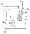
- the oral cavity cleaning device 10 of the present embodiment includes an electrolyzed water generating device 20 that electrolyzes water to generate electrolyzed water, and an injection device (cleaner) 30.
- the injection device 30 includes a main body 31 formed in a cylindrical shape having a size that can be held with one hand of a person.
- a cylindrical nozzle (cleaning nozzle) 32 for injecting electrolyzed water is provided at one end of the main body 31.
- the nozzle 32 is formed in a size that can be inserted into the oral cavity of the user.
- the main body 31 is connected to the electrolyzed water generating apparatus 20 via a flexible hose 40. Electrolyzed water is supplied from the electrolyzed water generator 20 to the injection device 30 through the hose 40.
- a switch 33 is provided on the surface of the main body 31 for determining whether or not the electrolyzed water is ejected from the nozzle 32.
- the injection device 30 is configured to inject the electrolyzed water generated by the electrolyzed water generating device 20 from the nozzle 32 while the switch 33 is pressed.
- the electrolyzed water generating apparatus 20 includes a water storage tank 21 and a housing 22 to which the water storage tank 21 is detachably attached.
- the electrolyzed water generator 20 includes an electrolyzer 23, an operation device 24, electrolyzed water supply means 25, a power source 26, and a drain tank 27.
- the operating device 24, the electrolyzed water supply means 25, the power source 26 and the drainage tank 27 are accommodated in the housing 22.
- the power source 26 is a DC power supply device that applies a DC voltage.
- the power source 26 is an AC-DC converter that generates a DC voltage based on AC power obtained from an AC power source (commercial AC power source) (not shown).
- the water storage tank 21 is formed of a resin material having translucency, for example.
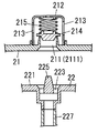
- Two water ports 211 are provided in the bottom wall of the water storage tank 21 in the thickness direction.
- a holding body 212 surrounding each water port 211 is disposed on the upper surface (inner bottom surface) of the bottom wall of the water storage tank 21, a holding body 212 surrounding each water port 211 is disposed.
- the holding body 212 is formed in a cylindrical shape, and the upper end opening is closed.
- a plurality of openings 213 are formed in the side wall of the holder 212 along the circumferential direction.
- a valve body 214 for closing the water port 211 is disposed in the holding body 212.
- a coil spring 215 is arranged in a compressed state between the valve body 214 and the upper wall of the holding body 212. The coil spring 215 urges the valve body 214 downward, whereby the water port 211 is blocked by the valve body 214.
- one water mouth (first water mouth) 211 is denoted by reference numeral 2111 and the other water mouth (second water mouth) 211 is denoted by reference numeral 2112 as necessary.
- the first water port 2111 is used for supplying water from the water storage tank 21 to the housing 22.
- the second water port 2112 is used for supplying electrolytic water from the housing 22 to the water storage tank 21.
- FIG. 5 shows a modification of the water storage tank 21.
- the water storage tank 21 is preferably configured so that it can be easily detached from the housing 22.
- a concave surface 216 for facilitating holding the water storage tank 21 is formed on the outer surface of the water storage tank 21 shown in FIGS. 5 (a) and 5 (b) and FIGS. 5 (c) and 5 (d).
- the concave surface 216 may be formed on a part of the outer surface of the water storage tank 21 as shown in FIGS. 5 (a) and 5 (b), or the water storage tank 21 as shown in FIGS. 5 (c) and 5 (d). It may be formed over the entire circumference of the outer surface.
- a handle 217 is formed on the outer surface of the water storage tank 21 shown in FIGS. Providing the handle 217 facilitates not only the operation of putting water into the water storage tank 21 but also the operation of using the electrolyzed water in the water storage tank 21 for other purposes such as drinking.
- the housing 22 is formed in a trapezoidal box shape. On the upper surface of the housing 22, a first placement surface 221 for placing the water storage tank 21 and a second placement surface 222 for placing the injection device 30 are formed. The first placement surface 221 is located above the second placement surface 222.
- a water inlet 223 for supplying the water in the water storage tank 21 to the electrolyzer 23 in the housing 22 and the electrolyzed water generated by the electrolyzer 23 are supplied into the water tank 21.
- a reflux port 224 is formed. In a state where the water storage tank 21 is attached to the housing 22, the water inlet 223 communicates with the first water port 2111, and the reflux port 224 communicates with the second water port 2112.
- a protrusion 225 is disposed at the center of the water inlet 223 and the reflux port 224.
- the protrusion 225 is configured to push up the valve body 214 against the urging force of the coil spring 215 when the water storage tank 21 is attached to the housing 22.
- the water port 211 is closed by the valve body 214, and the water in the water tank 21 does not flow out of the water port 211.
- the protrusion 225 pushes up the valve body 214 to open the water port 211, so that water can flow out from the water port 211.
- a housing recess 226 that houses the drainage tank 27 is formed on the side surface of the housing 22.
- the electrolyzer 23 has an electrolysis tank 231 to which water is supplied from the water storage tank 21.
- the electrolysis device 23 includes a positive electrode 232, a negative electrode 233, and a voltage application device 234 in order to electrolyze the water in the electrolytic cell 231 to generate electrolyzed water.
- the positive electrode 232 and the negative electrode 233 are disposed in the electrolytic cell 231.
- the voltage application device 234 applies a DC voltage between the positive electrode 232 and the negative electrode 233 using the power supply 26.
- the electrolyzer 23 electrolyzes the water supplied from the water storage tank 21 into the electrolytic tank 231, generates acidic water on the positive electrode 232 side, and generates alkaline water on the negative electrode 233 side.
- the electrolyzer 23 generates less acidic water per unit time than the generated amount per unit time of the alkaline water so that the acidic water does not overflow from the drain tank 27 during the generation of the electrolyzed water. It is comprised so that it may become.
- the electrolytic cell 231 has a water supply port (not shown) for introducing water from the water storage tank 21, a first drainage port (not shown) for discharging alkaline water, and a first port for discharging acidic water. 2 drain outlets (not shown) are provided.
- the water supply port of the electrolytic cell 231 is connected to the water inlet 223 by a water conduit 227 made of a water pipe (hose or pipe). Therefore, the water in the water storage tank 21 flows into the electrolytic tank 231 through the water conduit 227.
- the electrolyzer 23 includes a first drainage channel 235 made of a water pipe for supplying alkaline water discharged from the first drainage port of the electrolytic cell 231 to the electrolyzed water supply means 25.
- the electrolyzer 23 includes a second drainage channel 236 made of a water pipe for supplying the acid water discharged from the second drainage port of the electrolytic bath 231 to the drainage bath 27.
- the electrolyzer 23 supplies the electrolyzed water (alkaline water) generated on the negative electrode 233 side to the electrolyzed water supply means 25 and supplies the electrolyzed water (acidic water) generated on the positive electrode 232 side to the drainage tank 27.
- alkaline water is used as the cleaning water used for oral cleaning.
- the oral cavity cleaning device 10 of the present embodiment electrolysis and reflux of alkaline water are performed until the alkaline water stored in the water storage tank 21 becomes strong alkaline water having a pH of 10 or more. That is, strong alkaline water having a pH of 10 or more is used for oral cleaning. Strong alkaline water having a pH of 10 or more can sufficiently dissolve ⁇ -1,3-glucan constituting a biofilm.
- the reason why the pH is 10 or more is that alkaline water is not for drinking but for oral cleaning.
- the redox potential (ORP) of the alkaline water is preferably ⁇ 170 mV or less.
- the pH of the alkaline water is set to 12 or less.
- the redox potential of the alkaline water is preferably ⁇ 250 mV or more.
- the electrolyzer 23 is configured to generate strong alkaline water as electrolyzed water.
- the pH of strong alkaline water is preferably 10.5 or more and 11.5 or less, and the redox potential thereof is preferably ⁇ 250 mV or more and ⁇ 170 mV or less.
- the drain tank 27 is detachably attached to the housing 22. As shown in FIG. 3B, the drainage tank 27 is formed in a rectangular parallelepiped box shape having an upper surface opened. On the front surface of the drainage tank 27, a handle 271 for easily removing the drainage tank 27 from the housing recess 225 of the housing 22 is formed. The handle 271 is formed in, for example, a shape that can be hooked with a finger. Further, the drainage tank 27 may be provided with a water amount sensor (not shown) for detecting the amount of electrolyzed water (acidic water in this embodiment) in the drainage tank 27.
- the housing 22 may be provided with an alarm (not shown) that notifies the user with sound or the like when the amount of acidic water in the drainage tank 27 exceeds a certain amount. If it does in this way, it can prevent that acidic water overflows from the drainage tank 27.
- an alarm not shown
- the operation device 24 selects a first mode for generating electrolyzed water, a second mode for cleaning the oral cavity using the electrolyzed water generated in the first mode, and a third mode for stopping the operation. Used for.
- Such an operating device 24 includes, for example, a knob 241 that is exposed on the outer surface of the housing 22. One of the modes can be selected by operating the knob 241.
- the operation device 24 gives an electrolyzed water generation signal to the control device 255 of the electrolyzed water supply means 25, and when the second mode is selected, gives an electrolyzed water injection signal to the control device 255.
- a stop signal is given to the control device 255.
- the operating device 24 is also used for setting the amount of electrolyzed water sprayed from the nozzle 32 of the spray device 30 in the second mode.
- the injection water amount can be selected within a range from level 1 (weak: 100 ml / min) to level 5 (strong: 500 ml / min). As an example, there are five levels: Level 1 (100 ml / min), Level 2 (200 ml / min), Level 3 (300 ml / min), Level 4 (400 ml / min), and Level 5 (500 ml / min).
- the operating device 24 provides the control device 255 with an injection water amount instruction signal indicating the selected level.
- the setting of the amount of jet water can be performed by, for example, a knob 241.
- the electrolyzed water supply means 25 includes a first supply path 251 for supplying the electrolyzed water in the electrolyzer 231 to the water storage tank 21, and a second supply path for supplying the electrolyzed water in the electrolyzer 231 to the injection device 30. 252.
- the electrolyzed water supply means 25 includes a first pump (reflux pump) 253 that draws the electrolyzed water in the electrolyzer 231 into the first supply path 251, and a second pump that draws the electrolyzed water in the electrolyzer 231 into the second supply path 252.
- Two pumps (supply pump) 254 and a control device 255 are provided.
- Each supply path 251 and 252 is constituted by a water pipe. One end of each supply path 251, 252 is connected to the first drainage path 235. The other end of the first supply path 251 is connected to one end of the reflux path 228 via a check valve 256. The other end of the reflux path 228 is connected to the reflux port 225. The reflux path 228 supplies the electrolytic water in the electrolytic tank 231 to the water storage tank 21 from the reflux port 225.
- a first pump 253 is provided in the first supply path 251.
- the other end of the second supply path 252 is connected to the hose 40 via the second pump 254.
- An electromagnetic valve 257 is provided in the second supply path 252.
- the control device 255 is configured using, for example, an arithmetic processing device.
- the electrolyzed water generation signal is received from the operation device 24 (that is, when the first mode is selected)
- the second pump 254 is stopped and the first pump 253 and the voltage application device 234 are driven. Further, the control device 255 closes the electromagnetic valve 257.
- the electrolyzer 23 when the first mode is selected, the electrolyzer 23 generates electrolyzed water (alkaline water / acidic water). Alkaline water generated by the electrolyzer 23 is drawn into the first supply path 251 by the water pressure generated by the first pump 253, passes through the reflux path 228, the reflux port 225, and the second water port 2112, and enters the water storage tank 21. Supplied. At this time, since the second pump 254 is stopped and the electromagnetic valve 257 is closed, the alkaline water is not supplied to the injection device 30.
- the alkaline water generated by the electrolyzer 23 is supplied to the water tank 21. Therefore, the alkaline water generated by the electrolyzer 23 is mixed with the water in the water storage tank 21. Therefore, the water in the water storage tank 21 gradually changes to alkaline water, and eventually the water in the water storage tank 21 is converted into alkaline water.
- the control device 255 stops the voltage application device 234 and the first pump 253 when a predetermined condition is satisfied.
- the predetermined condition is that all the water in the water storage tank 21 has been converted into electrolyzed water, that is, the generation of electrolyzed water has been completed.
- the control device 255 determines that the predetermined condition is satisfied.
- a predetermined value for example, a value corresponding to pH 11
- the control device 255 satisfies the predetermined condition. to decide.
- the control device 255 when receiving the electrolyzed water injection signal from the operation device 24 (that is, when the second mode is selected), the control device 255 stops the first pump 253 and the voltage application device 234 and drives the second pump 254. To do. Further, the control device 255 opens the electromagnetic valve 257.
- the electrolyzer 23 does not generate electrolyzed water (alkaline water / acidic water), but the electrolyzer 23 generates electrolyzed water (generated by the electrolyzer 23 from the water storage tank 21, Alkaline water supplied to the water storage tank 21) is supplied.
- the alkaline water supplied to the electrolytic cell 23 is drawn into the second supply path 252 by the water pressure generated by the second pump 254, and supplied to the injection device 30 through the hose 40. At this time, since the first pump 253 is stopped, the alkaline water is not supplied to the water storage tank 21.
- the control device 255 controls the second pump 254 according to the jet water amount instruction signal received from the operation device 24.
- the control device 255 sets the jet water amount to a magnitude corresponding to the level indicated by the jet water amount instruction signal.
- control device 255 When the control device 255 receives a stop signal from the operation device 24 (that is, when the third mode is selected), the control device 255 stops the voltage application device 23 and both the pumps 253 and 254 and closes the electromagnetic valve 257.
- the electrolyzed water supply means 25 includes the first supply path 251, the second supply path 252, the first pump 253, the second pump 254, and the control device 255.
- the electrolyzed water supply means 25 supplies the electrolyzed water in the electrolyzer 231 to the water storage tank 21 when the first mode is selected by the operating device 24, and the electrolyzer 231 when the second mode is selected by the operating device 24. Then, electrolyzed water is supplied from the water storage tank 21 to the injection device 30.
- the third mode is selected by the operation device 24, and the water tank 21 is filled with raw water such as tap water.
- the water storage tank 21 may be removed from the housing 22.
- the water in the water storage tank 21 flows into the electrolytic tank 231 through the first water port 2111, the water inlet 223, and the water conduit 227.
- the first mode is selected by the operation device 24.
- the voltage application apparatus 234 operates and the water in the electrolytic cell 231 is electrolyzed.
- Alkaline water generated in the electrolyzer 23 is drawn into the first supply path 251 by the first pump 253, and flows into the water storage tank 21 through the reflux path 228, the reflux port 225, and the second water port 2112.
- the acidic water generated by the electrolyzer 23 is supplied to the drainage tank 27 through the second drainage channel 236.
- the drainage tank 27 may be removed from the housing 22 and the acidic water in the drainage tank 27 may be discarded in a washstand or the like.
- the alkaline water returned to the water storage tank 21 is mixed with the raw water that has been filled in the water storage tank 21 from the beginning. Then, mixed water of alkaline water and raw water is supplied from the water storage tank 21 to the electrolytic tank 231. Thus, the water circulates through the water storage tank 21 and the electrolytic tank 231 many times, so that the raw water filled in the water storage tank 21 is gradually changed to alkaline water.
- control device 255 stops the voltage application device 234 and the first pump 253. Note that the user may be notified of the end of the generation of alkaline water by light or sound.
- the second mode is selected by the operation device 24.
- the second pump 254 operates.
- the electromagnetic valve 257 is opened.
- the alkaline water in the water storage tank 21 is sucked into the second pump 254 through the first water inlet 2111, the water inlet 223, the water inlet 227, the electrolytic tank 231, the first drainage 235, and the second supply path 252. Then, it is discharged from the second pump 254 to the hose 40.
- the alkaline water discharged from the second pump 254 is supplied to the injection device 30 through the hose 40. If the switch 33 of the injection device 30 is pressed in this state, alkaline water is injected from the opening at the tip of the nozzle 32. Therefore, oral cleaning can be performed by applying alkaline water to the gums and tooth surfaces. Note that the strength of the alkaline water to be injected can be selected by the operation device 24.
- the water supplied from the water storage tank 21 is electrolyzed by the electrolyzer 23 to generate electrolyzed water, and the electrolyzed water generated by the electrolyzer 23 is used as the electrolyzed water.
- Supply to the water storage tank 21 By repeating this operation, the water in the water storage tank 21 is converted into electrolyzed water. That is, the water storage tank 21 serves as both a water storage tank for storing water for generating electrolyzed water and a water storage tank for storing the generated electrolyzed water. Therefore, it is not necessary to separately provide a water storage tank for storing the generated electrolyzed water. Therefore, it can be made smaller than before, and can be installed without problems in places where the space such as around the washstand is narrow.
- alkaline water generated by the electrolysis device 23 is supplied to the water storage tank 21, and acidic water generated by the electrolysis device 23 is supplied to the drainage tank 27.
- the acid water generated by the electrolyzer 23 may be supplied to the water storage tank 21, and the alkaline water generated by the electrolyzer 23 may be supplied to the drain tank 27.
- the main purpose of the mouth washing apparatus as described above is to remove a biofilm that causes caries.
- Biofilms are produced by caries-causing bacteria and are mainly composed of ⁇ -1,3 glucan, which is a polysaccharide.
- Japanese Published Patent Application No. 2008-1657 discloses that gargle with alkaline water can remove a biofilm that causes caries than gargle with tap water. This is thought to be because ⁇ -1,3 glucan, which is the main component of biofilm, does not dissolve very much in water but dissolves well in alkaline water.
- the biofilm described above has various forms depending on the oral environment, and the form is complicated. Therefore, it is desirable to combine the dissolving action of the alkaline water and the physical removal means in order to fully exhibit the excellent dissolving ability of the alkaline water.
- the electrolysis device 23 generates strong alkaline water as electrolysis water. Further, the amount of electrolyzed water (strong alkaline water) sprayed from the nozzle 32 of the spray device 30 is not less than 100 ml / min and not more than 500 ml / min.
- a biofilm dissolving ability test was performed.
- a bovine tooth enamel was cut to 5.5 mm ⁇ 5.5 mm ⁇ 2.0 mm, polished to water resistance, and ground to # 1200 SiC, thereby preparing Sample 50.
- a biofilm was formed on the sample 50 using the artificial oral cavity device 60 shown in FIG.
- the biofilm was formed by using phosphate buffered saline (PBS) and a plurality of cariogenic pathogens (Streptococcus mutans MT8148, Streptococcus) on the sample 50 fixed on the stage 61 of the artificial oral cavity device 60 (37 ° C. heat reflux).
- PBS phosphate buffered saline
- Streptococcus mutans MT8148, Streptococcus a plurality of cariogenic pathogens
- Sobrinus 6715, Streptococcus gordonii ATCC 10558, Streptococcus mitis ATCC 6249 suspension (OD500 2.5) and sucrose-containing HI medium (25 g / L sucrose, 10.0 g / L heart infusion, 10.0 g / L tryptose, 5.0 g / L sodium chloride) was continuously dropped over 20 hours.
- the sample 50 with the biofilm formed in this manner is washed by spraying strong alkaline water (pH 10.5, ORP-177 mV) or tap water (pH 7.2, ORP-12 mV) at room temperature. Note that the surface of the sample 50 was washed with PBS before washing with strong alkaline water or tap water.
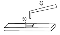
- FIG. 7 shows a state in which strong alkaline water or tap water is jetted from the nozzle 32 to the sample 50. In FIG. 7, the tip of the nozzle 32 is separated from the sample 50 by 1 cm. In addition, the jet direction of strong alkaline water or tap water is set to a direction perpendicular to the surface of the sample 50.
- the amount of cells (Turbidity) and the amount of glucan remaining in the sample 50 after washing were measured using a spectrophotometer (Biotrak II plate reader, Biochrom, Cambridge, UK). The obtained results were tested at a significance level of 5% using a two-factor analysis of variance (Two way ANOVA).
- FIG. 8A shows the amount of biofilm remaining in the sample 50 (Turbidity).
- FIG.8 (b) has shown the measurement result of the sample 50 and the glucan amount. Further, in each graph, ⁇ AW indicates the case where jet cleaning is performed with strong alkaline water, and ⁇ TW indicates the case where jet cleaning is performed using tap water.
- the amount of cells and glucan in the case of washing with strong alkaline water is significantly smaller than that in the case of washing with tap water in the residual amount (p ⁇ 0.05). . Therefore, it can be seen that spray cleaning with strong alkaline water is effective for removing the biofilm.
- the level 5 (strong) group tends to have less residual glucan than the level 1 (weak) group. This indicates that the removal effect of the biofilm is further increased by increasing the water pressure and the amount of water.
- the oral cleaning device 10 ⁇ / b> A of the present embodiment is different from the electrolyzed water generation device 20 in the first embodiment in the electrolyzed water generation device 20 ⁇ / b> A.
- symbol is attached
- illustration of the water tank 21 is abbreviate
- the electrolyzed water supply means 25A is different from the electrolyzed water supply means 25 in the first embodiment.
- the electrolyzed water supply means 25A includes a common path 250 to which the electrolyzed water in the electrolyzer 231 is supplied, a first supply path 251A for supplying the electrolyzed water flowing into the common path 250 to the water storage tank 21, and a common path 250. And a second supply path 252 ⁇ / b> A for supplying the electrolyzed water flowing into the injection device 30 to the injection device 30.
- the electrolyzed water supply means 25A includes a pump 258 that draws electrolyzed water in the electrolyzer 231 into the common path 250, a switching valve 259, and a control device 255A.
- the common channel 250 and the supply channels 251A and 252A are each constituted by a water pipe.
- One end of the common path 250 is connected to the first drainage path 235 via the pump 259.
- One end of the first supply path 251A is connected to the other end of the common path 250 via the switching valve 259.
- the other end of the first supply path 251A is connected to one end of the reflux path 228 via the check valve 256.
- One end of the second supply path 252A is connected to the other end of the common path 250 via the switching valve 259.
- the other end of the second supply path 252A is connected to the hose 40.
- the switching valve 259 is an electromagnetic valve, in which only the first supply path 251A is closed (only the second supply path 252A is opened) and only the second supply path 252A is closed (only the first supply path 251A). In the open state).
- the switching valve 259 is a three-way valve, and the first supply path 251A is closed (open / cleaning nozzle) and the second supply path 252A is closed (open / tank).
- the supply paths 251A and 252A can be switched to a closed state (closed).
- the switching valve 259 is disposed on the downstream side of the pump 258 and switches whether the alkaline water generated by the electrolysis device 23 is supplied to the water storage tank 21 or the injection device 30.
- the control device 255A drives the pump 258 and the voltage application device 234, and controls the switching valve 259 to close the second supply path 252A. Therefore, when the first mode is selected, the electrolyzer 23 generates electrolyzed water (alkaline water / acidic water). The alkaline water generated by the electrolyzer 23 is drawn into the common path 250 by the water pressure generated by the pump 258. At this time, since the second supply path 252A is closed by the switching valve 259, the alkaline water drawn into the common path 250 passes through the first supply path 251A, the return path 228, the return port 224, and the second water port 2112. Then, it is supplied to the water storage tank 21.
- the control device 255A When the control device 255A receives the electrolyzed water injection signal from the operation device 24, the control device 255A drives the pump 258 to stop the voltage application device 234. Further, the control device 255A controls the switching valve 259 to close the first supply path 251A. Therefore, when the second mode is selected, the electrolyzer 23 does not generate electrolyzed water (alkaline water / acidic water), but alkaline water is supplied from the water storage tank 21 to the electrolyzer 23. The alkaline water supplied to the electrolytic cell 23 is drawn into the common path 250 by the water pressure generated by the pump 258. At this time, since the first supply path 251A is closed by the switching valve 259, the alkaline water drawn into the common path 250 is supplied to the injection device 30 through the second supply path 252A and the hose 40.
- control device 255A When the control device 255A receives a stop signal from the operation device 24 (that is, when the third mode is selected), the control device 255A stops the voltage application device 23 and the pump 258, and both supply paths 251A and 252A by the switching valve 259. Close.
- the oral cleaning device 10A of the present embodiment in addition to the same effect as the oral cleaning device 10 of the first embodiment, unlike the oral cleaning device 10 of the first embodiment, only one pump is required. Can be made smaller. Therefore, it becomes easier to install the oral cleaning device around the washstand with a small space. Further, since the number of parts is reduced, there are advantages that the manufacturing cost can be reduced and the failure is less likely to occur.
- the oral cavity cleaning device 10 ⁇ / b> B of the present embodiment is different from the water storage tank 21 and the housing 22 in the first embodiment in the water storage tank 21 ⁇ / b> B and the housing 22 ⁇ / b> B.
- symbol is attached
- the water tank 21B is different from the water tank 21 of the first embodiment in that it has only one water port 211. That is, in the water storage tank 21B, the water port 211 is used for supplying water from the water storage tank 21B to the housing 22B and supplying electrolytic water from the housing 22B to the water storage tank 21B.
- a first opening 213 (2131) used for supplying water from the water storage tank 21B to the housing 22B and a supply of electrolyzed water from the housing 22B to the water storage tank 21B are provided on the side wall of the holding body 212 of the water storage tank 21B.
- the second opening 213 (2132) used in the above is formed.
- the first opening 2131 and the second opening 2132 are arranged to face each other.
- the casing 22 ⁇ / b> B has a circular hole 229 formed in the first placement surface 221.
- a protrusion 225 ⁇ / b> B is formed at the center of the hole 229.
- the protrusion 225 ⁇ / b> B divides the hole 229 into four equal parts in the circumferential direction to form two water inlets 223 and two reflux ports 224.
- the protrusion 225 ⁇ / b> B has a mixing prevention structure that prevents water flowing from the water port 211 to the water inlet 223 and electrolytic water flowing from the reflux port 224 to the water port 211 from being mixed.
- the protrusion 225 ⁇ / b> B has a plate-like partition 2251 that protrudes upward from the hole 229 and partitions the reflux port 224 and the water inlet 223.
- the upper end surface 2252 of the partition 2251 is formed so as to contact the lower surface 2141 of the valve body 214 without a gap.
- the side surface 2253 of the partition 2251 in the width direction (the normal direction of the paper surface in FIG. 11A) is formed in contact with the inner surface of the holding body 212 without a gap.
- each water inlet 223 and each reflux port 224 communicate with the water port 211 of the water storage tank 21B.
- the inside of the holding body 211 is divided into two parts by the valve body 214 and the partition 2251 of the protrusion 225B (in the example shown in FIG. 11A, it is divided into right and left).
- the water that has entered the holding body 212 from the first opening 2131 cannot move to the reflux port 224 side because of the valve body 214 and the partition 2251, and passes through the water port 211 and the water inlet 223. It flows into the housing 22B.
- the electrolyzed water that has entered the holding body 212 from the reflux port 224 through the water port 211 cannot move to the water inlet 223 side due to the valve body 214 and the partition 2251, and passes through the second opening 2132. It goes out of the holding body 212.
- the housing 22B includes the water inlet 223 communicating with the water outlet 211 of the water storage tank 21B, the water conduit 227 for supplying the water flowing in from the water inlet 223 to the electrolytic tank 231, and the water outlet 211 of the water storage tank 21B. And a reflux path 228 for supplying the electrolyzed water in the electrolytic bath 231 from the reflux port 224 to the water storage tank 21B. Further, the housing 22B includes a partition 2251 that partitions between the reflux port 224 and the water inlet 223.
- the mixing prevention structure in the present embodiment it is not possible to completely prevent the water flowing into the water inlet 223 from the water port 211 and the electrolytic water flowing into the water port 211 from the reflux port 224 from being mixed in the vicinity of the water port 211. .
- the water flowing into the water inlet 223 from the water port 211 and the electrolyzed water flowing into the water port 211 from the reflux port 224 are mixed, so there is no problem in adopting the above-described mixing prevention structure.
- the oral cleaning device 10 ⁇ / b> C of the present embodiment is different from the oral cleaning device 10 ⁇ / b> A of the second embodiment in that it includes a bubble generating unit (gas intake unit) 28.
- symbol is attached
- the bubble generating means 28 includes bubbles in the electrolyzed water by mixing gas into the electrolyzed water ejected from the nozzle 32.
- the bubble generating means 28 is provided in the second supply path 252A that is a water pipe between the nozzle 32 and the pump 258.
- negative pressure is generated in the expansion pipe 282 by passing the electrolytic water through the distal end side of the narrow pipe 281 having a small inner diameter.
- gas for example, air
- bubbles are included in the electrolytic water.
- ozone As a gas mixed in the electrolyzed water, ozone is listed. When ozone is mixed with electrolyzed water, a bactericidal effect can be expected. Moreover, it is preferable that the size of the bubble contained in electrolyzed water shall be micrometer size or nanometer size. Since shock waves are generated when micrometer-sized bubbles (microbubbles) or nanometer-sized bubbles (nanobubbles) disappear, an effect of removing plaque and the like can be obtained.
- strong alkaline water containing ozone can dissolve a larger amount of glucan than strong alkaline water not containing ozone, and exhibits high biofilm dispersibility.
- the oral cleaning device 10C of the present embodiment since the electrolytic water sprayed from the nozzle 32 contains bubbles, the cleaning power and the feeling of cleaning are improved.
- the bubble generating means 28 may be configured to mix gas into the electrolytic water in the water distribution pipe (second supply path 252A) through a T-shaped branch pipe by a pressure cylinder. However, according to the bubble generating means 28 using the venturi tube, the size can be reduced as compared with the case where the pressure cylinder is used.
- the bubble generating means 28 may be provided in the oral cleaning device 10 of the first embodiment.
Landscapes
- Health & Medical Sciences (AREA)
- Dentistry (AREA)
- Epidemiology (AREA)
- Life Sciences & Earth Sciences (AREA)
- Animal Behavior & Ethology (AREA)
- General Health & Medical Sciences (AREA)
- Public Health (AREA)
- Veterinary Medicine (AREA)
- Water Treatment By Electricity Or Magnetism (AREA)
Abstract
口腔洗浄装置(10)は、水を電気分解して電解水を生成する電解水生成装置(20)と、電解水生成装置(20)で生成された電解水をノズル(32)から噴射する噴射装置(30)とを備える。電解水生成装置(20)は、貯水槽(21)と、貯水槽(21)から水が供給される電解槽(231)内の水を電気分解して電解水を生成する電解装置(23)と、電解水を生成するための第1モードと口腔を洗浄するための第2モードとの選択に用いられる操作装置(24)とを備える。さらに、電解水生成装置(20)は、操作装置(24)で第1モードが選択されると電解槽(231)内の電解水を貯水槽(21)に供給し、操作装置(24)で第2モードが選択されると電解槽(231)を介して貯水槽(21)から電解水を噴射装置(30)に供給する電解水供給手段(25)を備える。
Description
本発明は、電解水を口腔内に噴射して口腔洗浄を行うための口腔洗浄装置に関する。
日本国公開特許公報5-76550や日本国公開特許公報10-33571には、電解水を生成して、ノズルから噴射する口腔洗浄装置が開示されている。
口腔洗浄装置は、洗面台等での歯磨き後に使用されることが多い。そのため、口腔洗浄装置を洗面台等の近くに設置したいという要望がある。しかしながら、従来の口腔洗浄装置は、電解水を生成するための水を貯めておく第1貯水槽とは別に、口腔洗浄に用いる電解水を貯めておく第2貯水槽を備えているため、比較的大きい。そのため、一般にスペースが狭い洗面台周りに置くことが困難であった。
本発明は上記問題点に鑑みて為され、その目的は、小型化できる口腔洗浄装置を提供することである。
本発明に係る口腔洗浄装置は、水を電気分解して電解水を生成する電解水生成装置と、上記電解水生成装置で生成された電解水をノズルから噴射する噴射装置とを備える。上記電解水生成装置は、貯水槽と、上記貯水槽から水が供給される電解槽を有し上記電解槽内の水を電気分解して電解水を生成する電解装置と、電解水を生成するための第1モードと口腔を洗浄するための第2モードとの選択に用いられる操作装置とを備える。さらに、電解水生成装置は、上記操作装置で上記第1モードが選択されると上記電解槽内の電解水を上記貯水槽に供給し、上記操作装置で上記第2モードが選択されると上記電解槽を介して上記貯水槽から電解水を上記噴射装置に供給する電解水供給手段を備える。
この発明によれば、上記貯水槽から供給された水を上記電解装置で電気分解して電解水を生成し、上記電解装置で生成された電解水を上記貯水槽に供給する。この動作が繰り返されることで、上記貯水槽内の水が電解水に変換される。つまり、上記貯水槽で、電解水を生成するための水を貯めておく貯水槽と、生成された電解水を貯めておくための貯水槽とを兼用している。そのため、生成された電解水を貯めておく貯水槽を別途設ける必要がない。よって、従来よりも小型化でき、例えば洗面台周り等のスペースが狭い場所にも問題なく設置できる。
好ましくは、上記電解水供給手段は、電解水を上記貯水槽に供給するための第1供給路と、電解水を上記噴射装置に供給するための第2供給路と、上記電解槽内の電解水を上記第1供給路に引き込む第1ポンプと、上記電解槽内の電解水を上記第2供給路に引き込む第2ポンプとを備える。さらに、上記電解水供給手段は、上記操作装置で上記第1モードが選択されると上記第2ポンプを停止して上記第1ポンプを駆動し、上記操作装置で上記第2モードが選択されると上記第1ポンプを停止して上記第2ポンプを駆動する制御装置を備える。
あるいは、上記電解水供給手段は、上記電解槽内の電解水が供給される共通路と、上記共通路に流入した電解水を上記貯水槽に供給するための第1供給路と、上記共通路に流入した電解水を上記噴射装置に供給するための第2供給路と、上記電解槽内の電解水を上記共通路に引き込むポンプとを備える。また、上記電解水供給手段は、上記第1供給路を閉じた状態と上記第2供給路を閉じた状態とを切り替え可能な切替弁を備える。さらに、上記電解水供給手段は、上記操作装置で上記第1モードが選択されると上記切替弁を制御して上記第2供給路を閉じ、上記操作装置で上記第2モードが選択されると上記切替弁を制御して上記第1供給路を閉じる制御装置を備える。
この構成によれば、ポンプが1つだけで済むから、より小型化できる。
好ましくは、上記電解水生成装置は、排水槽を着脱自在に備える。上記電解装置は、正極側と負極側とのいずれか一方で生成された電解水を上記電解水供給手段に供給し、上記正極側と上記負極側とのいずれか他方で生成された電解水を上記排水槽に供給するように構成される。
この構成によれば、不要な電解水を上記排水槽に貯めておくことができる。したがって、口腔洗浄装置を必ずしも排水口の近くに設置しなくて済む。そのため、口腔洗浄装置の設置場所の自由度が高くなる。
好ましくは、上記電解水生成装置は、上記電解装置と上記電解水供給手段とを収納する筐体を備える。上記筐体には、上記貯水槽が着脱自在に取り付けられる。上記貯水槽は、上記貯水槽内から上記筐体への水の供給と上記筐体から上記貯水槽内への電解水の供給とに用いられる水口を備える。上記筐体は、上記貯水槽の上記水口と連通する導水口と、上記導水口から流入した水を上記電解槽に供給する導水路と、上記貯水槽の上記水口と連通する還流口と、上記電解槽内の電解水を上記還流口から上記貯水槽に供給する還流路と、上記還流口と上記導水口との間を仕切る仕切とを備える。
この構成によれば、上記貯水槽に上記水口を1つ設けるだけでよいから、より小型化できる。
好ましくは、上記ノズルから噴射される電解水に気泡を含ませる気泡発生手段を備える。
この構成によれば、洗浄力や洗浄感が向上する。
好ましくは、上記気泡発生手段は、ベンチュリ管により構成される。
この構成によれば、圧力ボンベを用いる場合に比べれば、小型化を図ることができる。
好ましくは、上記電解装置は、電解水として強アルカリ水を生成するように構成される。
この構成によれば、強アルカリ水によるバイオフィルムの溶解効果と、噴射水圧によるバイオフィルムの剥離効果との相乗効果によって、バイオフィルムを効果的に除去できる。特に、電解水が直接当たった部位では歯表面からバイオフィルムがほぼ全て剥離される。歯の複雑な構造を考慮すれば、歯間部等の隙間に特に有効である。
より好ましくは、上記強アルカリ水のpHは10.5以上11.5以下であり、上記強アルカリ水の酸化還元電位は-250mV以上-170mV以下である。
この構成によれば、誤飲等により人体に悪影響を及ぼすことのない範囲内で、バイオフィルムを構成するα-1,3-グルカンを十分に溶解させることができる。
さらに好ましくは、上記噴射装置の上記ノズルから噴射される電解水の噴射水量が、100ml/分以上500ml/分以下になるように構成される。
この構成によれば、バイオフィルムを効果的に剥離させて除去できる。
(実施形態1)
図1,2に示すように、本実施形態の口腔洗浄装置10は、水を電気分解して電解水を生成する電解水生成装置20と、噴射装置(洗浄器)30とを備える。
図1,2に示すように、本実施形態の口腔洗浄装置10は、水を電気分解して電解水を生成する電解水生成装置20と、噴射装置(洗浄器)30とを備える。
噴射装置30は、人の片手で把持できる大きさの筒型に形成された本体31を備える。本体31の一端には、電解水を噴射するための筒状のノズル(洗浄ノズル)32が設けられている。ノズル32は、使用者の口腔内に挿入可能な大きさに形成されている。本体31は、可撓性を有するホース40を介して電解水生成装置20に接続される。電解水生成装置20から噴射装置30には、ホース40を通して電解水が供給される。本体31の表面には、ノズル32から電解水を噴射するかどうかを決定するためのスイッチ33が設けられる。例えば、噴射装置30は、スイッチ33が押圧されている間は、電解水生成装置20で生成された電解水をノズル32から噴射するように構成される。
電解水生成装置20は、貯水槽21と、貯水槽21が着脱自在に取り付けられる筐体22とを備える。また、電解水生成装置20は、電解装置23と、操作装置24と、電解水供給手段25と、電源26と、排水槽27とを備える。操作装置24と、電解水供給手段25と、電源26と、排水槽27とは筐体22に収納される。
電源26は、直流電圧を与える直流電源装置である。例えば、電源26は、図示しない交流電源(商用交流電源)より得た交流電力を元に直流電圧を生成するAC-DCコンバータである。
貯水槽21は、例えば透光性を有する樹脂材料により形成される。貯水槽21の底壁には、2つの水口211が厚み方向に貫設されている。
図4に示すように、貯水槽21の底壁の上面(内底面)には、各水口211を囲う保持体212が配置される。保持体212は、筒状に形成され、上端の開口が閉塞されている。また、保持体212の側壁には、開口213が周方向に沿って複数形成されている。保持体212内には、水口211を塞ぐ弁体214が配置される。弁体214と保持体212の上壁との間には、コイルばね215が圧縮状態で配置される。コイルばね215は、弁体214を下方に付勢し、これによって、水口211が弁体214で塞がれる。
本実施形態において、必要に応じて、一方の水口(第1の水口)211を符号2111で示し、他方の水口(第2の水口)211を符号2112で示す。第1の水口2111は、貯水槽21から筐体22への水の供給に用いられる。第2の水口2112は、筐体22から貯水槽21への電解水の供給に用いられる。
図5は、貯水槽21の変形例を示す。貯水槽21は、筐体22から容易に取り外しができるように構成されることが好ましい。例えば、図5(a),(b)や、図5(c),(d)に示す貯水槽21の外面には、貯水槽21を持ち易くするための凹面216が形成されている。凹面216は、図5(a),(b)に示すように貯水槽21の外面の一部に形成されていてもよいし、図5(c),(d)に示すように貯水槽21の外面の全周に亘って形成されていてもよい。図5(e),(f)に示す貯水槽21の外面には、把手217が形成されている。把手217を設ければ、貯水槽21に水を入れる作業だけではなく、貯水槽21内の電解水を飲用等の他の用途に使用する作業も行いやすくなる。
筐体22は、台形の箱状に形成される。筐体22の上面には、貯水槽21を載置するための第1載置面221と、噴射装置30を載置するための第2載置面222とが形成される。第1載置面221は、第2載置面222より上方に位置する。
第1載置面221には、貯水槽21内の水を筐体22内の電解装置23に供給するための導水口223と、電解装置23で生成された電解水を貯水槽21内に供給するための還流口224とが形成される。貯水槽21を筐体22に取り付けた状態では、導水口223は第1の水口2111と連通し、還流口224は第2の水口2112と連通する。
導水口223および還流口224の中央には、突起225が配置される。突起225は、貯水槽21を筐体22に取り付けた際に、コイルばね215の付勢力に抗して弁体214を押し上げるように構成される。
したがって、貯水槽21を筐体22から取り外した状態では、水口211は弁体214で閉じられ、貯水槽21内の水が水口211から流出することがない。一方、貯水槽21を筐体22に取り付けた状態では、突起225が弁体214を押し上げることで、水口211が開放されるから、水口211から水が流出可能になる。
筐体22の側面には、図1および図3(a),(b)に示すように、排水槽27を収納する収納凹所226が形成されている。
電解装置23は、貯水槽21から水が供給される電解槽231を有する。電解装置23は、電解槽231内の水を電気分解して電解水を生成するために、正極232と、負極233と、電圧印加装置234とを備える。正極232と負極233とは電解槽231内に配置される。電圧印加装置234は、電源26を利用して、正極232と負極233との間に直流電圧を印加する。電解装置23は、貯水槽21より電解槽231内に供給された水を電気分解して、正極232側で酸性水を生成し、負極233側でアルカリ水を生成する。なお、電解装置23は、電解水の生成中に排水槽27から酸性水が溢れ出すことがないように、酸性水の単位時間当たりの生成量がアルカリ水の単位時間当たりの生成量よりも少なくなるように構成されている。
電解槽231には、貯水槽21から水を入れるための給水口(図示せず)と、アルカリ水を排出するための第1排水口(図示せず)と、酸性水を排出するための第2排水口(図示せず)とが設けられる。電解槽231の給水口は、配水管(ホースやパイプ)よりなる導水路227によって導水口223に接続される。したがって、貯水槽21内の水は導水路227を通って電解槽231内に流入する。
電解装置23は、電解槽231の第1排水口から排出されるアルカリ水を電解水供給手段25に供給するための配水管よりなる第1排水路235を備える。また、電解装置23は、電解槽231の第2排水口から排出される酸性水を排水槽27に供給するための配水管よりなる第2排水路236を備える。
このように電解装置23は、負極233側で生成された電解水(アルカリ水)を電解水供給手段25に供給し、正極232側で生成された電解水(酸性水)を排水槽27に供給する。つまり、本実施形態の口腔洗浄装置10では、アルカリ水を口腔洗浄に用いる洗浄水としている。
特に本実施形態の口腔洗浄装置10では、貯水槽21内に貯留されるアルカリ水がpH10以上の強アルカリ水となるまで電気分解およびアルカリ水の還流を行う。つまり、口腔洗浄には、pH10以上の強アルカリ水を用いる。pH10以上の強アルカリ水は、バイオフィルムを構成するα-1,3-グルカンを十分に溶解させることができる。pH10以上としたのは、アルカリ水が飲用ではなく口腔洗浄用だからである。また、この際のアルカリ水の酸化還元電位(ORP)は-170mV以下とすることが好ましい。
ただし、アルカリ水のpHが高すぎると、アルカリ水の誤飲時に血中カリウム値が上昇するなど、人体に悪影響を及ぼすおそれがある。そこで、口腔洗浄装置10ではアルカリ水のpHを12以下にする。また、アルカリ水の酸化還元電位も-250mV以上とすることが好ましい。
つまり、電解装置23は、電解水として強アルカリ水を生成するように構成される。特に、強アルカリ水のpHは10.5以上11.5以下とすることが好ましく、その酸化還元電位は-250mV以上-170mV以下であることが好ましい。
排水槽27は、筐体22に着脱自在に取り付けられる。排水槽27は、図3(b)に示すように、上面が開口された直方体の箱状に形成される。排水槽27の前面には、排水槽27を筐体22の収納凹所225から容易に取り出すための把手271が形成されている。把手271は、例えば、指を引っ掛けることができる形状に形成される。また、排水槽27に、排水槽27内の電解水(本実施形態では、酸性水)の量を検知する水量センサ(図示せず)を設けてもよい。この場合、筐体22に、排水槽27内の酸性水の量が一定量を越えたときに使用者に音等で報知を行う報知器(図示せず)を設ければよい。このようにすれば、排水槽27から酸性水が溢れ出してしまうことを防止できる。
操作装置24は、電解水を生成するための第1モードと、第1モードで生成された電解水を用いて口腔を洗浄するための第2モードと、動作を停止する第3モードとの選択に用いられる。このような操作装置24は、例えば、筐体22の外面に露設される摘み241を備える。摘み241を操作することで、いずれかのモードを選択することができる。操作装置24は、第1モードが選択されると電解水生成信号を電解水供給手段25の制御装置255に与え、第2モードが選択されると電解水噴射信号を制御装置255に与え、第3モードが選択されると停止信号を制御装置255に与える。
また、操作装置24は、第2モードにおいて、噴射装置30のノズル32から噴射する電解水の噴射水量の設定にも用いられる。例えば、噴射水量は、レベル1(弱:100ml/分)からレベル5(強:500ml/分)までの範囲内で選択可能である。一例としては、レベル1(100ml/分)、レベル2(200ml/分)、レベル3(300ml/分)、レベル4(400ml/分)、レベル5(500ml/分)の5段階である。操作装置24は、選択されたレベルを示す噴射水量指示信号を制御装置255に与える。噴射水量の設定は、例えば、摘み241により行える。
電解水供給手段25は、電解槽231内の電解水を貯水槽21に供給するための第1供給路251と、電解槽231内の電解水を噴射装置30に供給するための第2供給路252とを備える。また、電解水供給手段25は、電解槽231内の電解水を第1供給路251に引き込む第1ポンプ(還流ポンプ)253と、電解槽231内の電解水を第2供給路252に引き込む第2ポンプ(供給ポンプ)254と、制御装置255とを備える。
各供給路251,252は、配水管により構成される。各供給路251,252の一端は、第1排水路235に接続されている。第1供給路251の他端は、逆止弁256を介して、還流路228の一端に接続される。還流路228の他端は、還流口225に接続される。この還流路228は、電解槽231内の電解水を還流口225から貯水槽21に供給する。第1供給路251には、第1ポンプ253が設けられている。第2供給路252の他端は、第2ポンプ254を介して、ホース40に接続されている。第2供給路252には、電磁弁257が設けられている。
制御装置255は、例えば、演算処理装置を用いて構成される。操作装置24より電解水生成信号を受信すると(すなわち第1モードが選択されると)、第2ポンプ254を停止させるとともに、第1ポンプ253および電圧印加装置234を駆動する。また、制御装置255は、電磁弁257を閉じる。
そのため、第1モードが選択されると、電解装置23は、電解水(アルカリ水・酸性水)を生成する。電解装置23で生成されたアルカリ水は、第1ポンプ253が生じさせる水圧によって、第1供給路251に引き込まれ、還流路228、還流口225、第2の水口2112を経て、貯水槽21に供給される。このとき、第2ポンプ254が停止し、電磁弁257が閉じられているので、噴射装置30にアルカリ水は供給されない。
このように第1モードでは、電解装置23で生成されたアルカリ水が貯水槽21に供給される。そのため、電解装置23で生成されたアルカリ水は、貯水槽21内の水と混ざる。そのため、貯水槽21内の水は徐々にアルカリ水へと変化していき、やがて、貯水槽21内の水がアルカリ水に変換される。制御装置255は、所定の条件が満たされると、電圧印加装置234および第1ポンプ253を停止させる。所定の条件とは、貯水槽21内の水が全て電解水に変換されたこと、つまり電解水の生成が終了したことである。例えば、制御装置255は、貯水槽21内に設置されたpHセンサ(図示せず)の検出値が所定値(例えばpH11に対応する値)になると、上記所定の条件を満たしたと判断する。この他、制御装置255は、第1モードの開始時から所定時間経過したときや第1モードの開始後の電解装置23の消費電力が所定量を越えたときに、上記所定の条件を満たしたと判断する。
一方、制御装置255は、操作装置24より電解水噴射信号を受信すると(すなわち第2モードが選択されると)、第1ポンプ253および電圧印加装置234を停止させるとともに、第2ポンプ254を駆動する。また、制御装置255は、電磁弁257を開く。
そのため、第2モードが選択されると、電解装置23は、電解水(アルカリ水・酸性水)を生成しないが、電解槽23には、貯水槽21から電解水(電解装置23で生成され、貯水槽21に供給されたアルカリ水)が供給される。電解槽23に供給されたアルカリ水は、第2ポンプ254が生じさせる水圧によって、第2供給路252に引き込まれ、ホース40を通って、噴射装置30に供給される。このとき、第1ポンプ253が停止しているので、貯水槽21にアルカリ水は供給されない。
また、第2モードにおいて、制御装置255は、操作装置24より受信した噴射水量指示信号に応じて、第2ポンプ254を制御する。これによって、制御装置255は、噴射水量を噴射水量指示信号で指示されたレベルに対応する大きさに設定する。
なお、制御装置255は、操作装置24より停止信号を受信すると(すなわち第3モードが選択されると)、電圧印加装置23および両ポンプ253,254を停止させるとともに、電磁弁257を閉じる。
このように、電解水供給手段25は、第1供給路251と、第2供給路252と、第1ポンプ253と、第2ポンプ254と、制御装置255とを備える。電解水供給手段25は、操作装置24で第1モードが選択されると電解槽231内の電解水を貯水槽21に供給し、操作装置24で第2モードが選択されると電解槽231を介して貯水槽21から電解水を噴射装置30に供給する。
次に、本実施形態の口腔洗浄装置10の使用方法について説明する。
まず、操作装置24により第3モードを選択し、貯水槽21に水道水等の原水を充填する。このとき、必要であれば、貯水槽21を筐体22から取り外せばよい。貯水槽21内の水は、第1の水口2111、導水口223、導水路227を通って、電解槽231に流れ込む。
次に、操作装置24により第1モードを選択する。これにより、電圧印加装置234が動作して、電解槽231内の水が電気分解される。電解装置23で生成されたアルカリ水は、第1ポンプ253によって第1供給路251に引き込まれ、還流路228、還流口225、第2の水口2112を通って、貯水槽21に流れ込む。
一方、電解装置23で生成された酸性水は、第2排水路236を通じて排水槽27に供給される。なお、排水槽27に酸性水がある程度溜まったら、筐体22から排水槽27を取り外して排水槽27内の酸性水を洗面台等に廃棄すればよい。
貯水槽21に還流されたアルカリ水は、当初から貯水槽21内に充填してあった原水と混ざる。そして、アルカリ水と原水との混合水が、貯水槽21から電解槽231に供給される。このように水が貯水槽21と電解槽231とを何回も循環することで、貯水槽21内に充填された原水が徐々にアルカリ水に変化していく。
やがて、貯水槽21内の水が全てアルカリ水に変換されると、制御装置255は、電圧印加装置234および第1ポンプ253を停止させる。なお、アルカリ水の生成が終わったことは、光や音などで使用者に通知するようにしてもよい。
第1モードで生成された電解水を用いて口腔洗浄を行うには、操作装置24により第2モードを選択する。これにより、第2ポンプ254が動作する。また、電磁弁257が開かれる。この場合、貯水槽21内のアルカリ水は、第1の水口2111、導水口223、導水路227、電解槽231、第1排水路235、第2供給路252を通って第2ポンプ254に吸い込まれ、第2ポンプ254からホース40に吐き出される。
第2ポンプ254から吐き出されたアルカリ水は、ホース40を通って噴射装置30に供給される。この状態で、噴射装置30のスイッチ33を押圧すれば、ノズル32の先端の開口からアルカリ水が噴射される。したがって、歯茎や歯面にアルカリ水を当てて口腔洗浄を行うことができる。なお、噴射されるアルカリ水の強さは、操作装置24で選択できる。
以上述べたように本実施形態の口腔洗浄装置10によれば、貯水槽21から供給された水を電解装置23で電気分解して電解水を生成し、電解装置23で生成された電解水を貯水槽21に供給する。この動作が繰り返されることで、貯水槽21内の水が電解水に変換される。つまり、貯水槽21が、電解水を生成するための水を貯めておく貯水槽と、生成された電解水を貯めておくための貯水槽とを兼ねている。そのため、生成された電解水を貯めておく貯水槽を別途設ける必要がない。よって、従来よりも小型化でき、例えば洗面台周り等のスペースが狭い場所にも問題なく設置できる。
本実施形態の口腔洗浄装置10では、電解装置23で生成されたアルカリ水を貯水槽21に供給し、電解装置23で生成された酸性水を排水槽27に供給している。逆に、電解装置23で生成された酸性水を貯水槽21に供給し、電解装置23で生成されたアルカリ水を排水槽27に供給するようにしてもよい。
ところで、上述したような口腔洗浄装置の主な目的は、う蝕の原因となるバイオフィルムを除去することである。バイオフィルムは、う蝕の原因菌により産生され、主に多糖類であるα―1,3グルカンから構成される。ここで、日本国公開特許公報2008-1657には、アルカリ水でうがいをすれば、水道水でうがいをする場合よりも、う蝕の原因となるバイオフィルムを除去できることが開示されている。これは、バイオフィルムの主構成要素であるα-1,3グルカンが、水にはあまり溶解しないが、アルカリ水には良く溶解するからであると考えられている。
上述したバイオフィルムは、口腔環境によって多様な形態を持ち、その形態は複雑である。そのため、アルカリ水の優れた溶解能を十分に発揮させるためには、アルカリ水の溶解作用と、物理的な除去手段とを組み合わせることが望ましい。
このような点を考慮し、本実施形態の口腔洗浄装置10では、電解装置23は、電解水として強アルカリ水を生成する。さらに、噴射装置30のノズル32から噴射される電解水(強アルカリ水)の噴射水量が、100ml/分以上500ml/分以下である。
したがって、本実施形態の口腔洗浄装置10によれば、強アルカリ水によるバイオフィルムの溶解効果と、噴射水圧によるバイオフィルムの剥離効果との相乗効果によって、バイオフィルムを効果的に除去できる。特に、電解水が直接当たった部位では歯表面からバイオフィルムがほぼ全て剥離される。歯の複雑な構造を考慮すれば、歯間部等の隙間に特に有効である。特に、強アルカリ水のpHは10.5以上11.5以下であり、強アルカリ水の酸化還元電位は-250mV以上-170mV以下である。したがって、誤飲等により人体に悪影響を及ぼすことのない範囲内で、バイオフィルムを構成するα-1,3-グルカンを十分に溶解させることができる。
本実施形態の口腔洗浄装置10の効果を確認するために、バイオフィルム溶解能の試験を行った。この試験では、牛歯のエナメル質を5.5mm×5.5mm×2.0mmとなるように切断し、耐水研磨して♯1200SiCまで研削することで、試料50を作製した。
この試料50には、図6に示す人工口腔装置60を用いて、バイオフィルムを形成した。バイオフィルムの形成は、人工口腔装置60(37℃温熱還流)のステージ61上に固定された試料50に、リン酸緩衝生理食塩水(PBS)と、複数のう蝕病原菌(Streptococcus mutans MT8148、Streptococcus sobrinus 6715、Streptococcus gordonii ATCC10558、Streptococcus mitis ATCC6249)の懸濁液(OD500=2.5)と、スクロース入りHI培地(25g/Lスクロース、10.0g/Lハートインフュージョン、10.0g/Lトリプトース、5.0g/L塩化ナトリウム)とを20時間に亘って連続的に滴下することで行った。
このようにしてバイオフィルムが形成された試料50に、常温において強アルカリ水(pH10.5、ORP-177mV)または水道水(pH7.2、ORP-12mV)を噴射して洗浄する。なお、強アルカリ水または水道水による洗浄を行う前に、試料50の表面をPBSで洗浄した。図7は、ノズル32から試料50に強アルカリ水または水道水を噴射する様子を示す。図7では、ノズル32の先端を試料50から1cm離している。また、強アルカリ水または水道水の噴射方向を試料50の表面に対して垂直な方向にしている。
試料50に強アルカリ水または水道水を噴射する時間(噴射洗浄時間)は10秒間とした。また、洗浄強さ(噴射水量)はレベル1(100ml/分)とレベル5(500ml/分)との2種類を用いた。つまり、レベル1の洗浄強さで強アルカリ水を試料50に10秒間噴射する実験と、レベル5の洗浄強さで強アルカリ水を試料50に10秒間噴射する実験と、レベル1の洗浄強さで水道水を試料50に10秒間噴射する実験と、レベル5の洗浄強さで水道水を試料50に10秒間噴射する実験とを行った。各実験には、4つの試料50を用いた。
洗浄後に試料50に残存したバイオフィルムの菌体量(Turbidity)およびグルカン量を、分光光度計(BiotrakII plate reader,Biochrom,Cambridge,UK)を用いて測定した。得られた結果については2要因の分散分析(Two way ANOVA)を用いて有意水準5%にて検定を行った。
図8(a)は、試料50に残存したバイオフィルムの菌体量(Turbidity)を示す。図8(b)は、試料50におよびグルカン量の測定結果を示している。また、各グラフ中の□AWは強アルカリ水で噴射洗浄した場合、■TWは水道水で噴射洗浄した場合を示している。
この測定結果によれば、強アルカリ水で洗浄した場合の菌体量およびグルカン量は、その残留量において水道水で洗浄した場合と比較して有意に少ないことがわかる(p<0.05)。したがって、バイオフィルムの除去に関しては、強アルカリ水の噴射洗浄が有効であることがわかる。特にグルカン量に関しては、レベル5(強)群のほうがレベル1(弱)群よりもグルカンの残存量が少なくなる傾向がある。これは、水圧や水量の増加によってバイオフィルムの除去効果が更に増大することを示す。
また、洗浄後の各試料50の表面を、走査型電子顕微鏡(SEM)で観察した。
図9は、試料50の表面のSEM観察の結果を示す。図9(a),(b)に示す画像(SEM画像)は強アルカリ水で洗浄された試料50を示す。特に、図9(a)はSEM画像を50倍に拡大した画像であり、(b)はSEM画像を1000倍に拡大した画像である。図9(c),(d)に示す画像(SEM画像)は水道水で洗浄された試料50を示す。特に、図9(c)はSEM画像を50倍に拡大した画像であり、(d)はSEM画像を1000倍に拡大した画像である。
この観察結果によれば、強アルカリ水および水道水は共に、試料50上に形成されたバイオフィルムを試料50の界面(表面)から剥離させることが認められる。特に強アルカリ水は、水道水よりもバイオフィルムを試料50から剥離させることが認められる。このことは、図8に示す結果を裏付ける。
(実施形態2)
図10に示すように、本実施形態の口腔洗浄装置10Aは、電解水生成装置20Aが実施形態1における電解水生成装置20と異なる。なお、本実施形態の口腔洗浄装置10Aと実施形態1の口腔洗浄装置10とで共通する構成については、同一の符号を付して説明を省略する。また、図10では、貯水槽21の図示を省略する。
図10に示すように、本実施形態の口腔洗浄装置10Aは、電解水生成装置20Aが実施形態1における電解水生成装置20と異なる。なお、本実施形態の口腔洗浄装置10Aと実施形態1の口腔洗浄装置10とで共通する構成については、同一の符号を付して説明を省略する。また、図10では、貯水槽21の図示を省略する。
電解水生成装置20Aは、電解水供給手段25Aが実施形態1における電解水供給手段25と異なる。
電解水供給手段25Aは、電解槽231内の電解水が供給される共通路250と、共通路250に流入した電解水を貯水槽21に供給するための第1供給路251Aと、共通路250に流入した電解水を噴射装置30に供給するための第2供給路252Aとを備える。
また、電解水供給手段25Aは、電解槽231内の電解水を共通路250に引き込むポンプ258と、切替弁259と、制御装置255Aとを備える。
共通路250および各供給路251A,252Aは、配水管により構成される。共通路250の一端は、ポンプ259を介して第1排水路235に接続される。第1供給路251Aの一端は、切替弁259を介して共通路250の他端に接続される。第1供給路251Aの他端は、逆止弁256を介して、還流路228の一端に接続される。第2供給路252Aの一端は、切替弁259を介して共通路250の他端に接続される。第2供給路252Aの他端は、ホース40に接続される。
切替弁259は、電磁弁であり、第1供給路251Aのみを閉じた状態(第2供給路252Aのみを開いた状態)と第2供給路252Aのみを閉じた状態(第1供給路251Aのみを開いた状態)とを切り替え可能に構成される。特に本実施形態では、切替弁259は、三方弁であり、第1供給路251Aを閉じた状態(開・洗浄ノズル)と、第2供給路252Aを閉じた状態(開・タンク)と、両供給路251A,252Aを閉じた状態(閉)とを切り替え可能である。切替弁259は、ポンプ258の下流側に配置されており、電解装置23で生成されたアルカリ水を貯水槽21または噴射装置30のいずれに供給するかを切り替える。
このように、電解水生成装置20Aでは、電解装置23の負極側と還流口224とを接続する配水管に、当該配水管の上流側から下流側へと、ポンプ258、切替弁259、逆止弁256がこの順に介在されている。また、切替弁259から電解水供給用の配水管が分岐している。
制御装置255Aは、操作装置24より電解水生成信号を受信すると、ポンプ258および電圧印加装置234を駆動するとともに、切替弁259を制御して第2供給路252Aを閉じる。そのため、第1モードが選択されると、電解装置23は、電解水(アルカリ水・酸性水)を生成する。電解装置23で生成されたアルカリ水は、ポンプ258が生じさせる水圧によって、共通路250に引き込まれる。このとき、第2供給路252Aは切替弁259により閉じられているから、共通路250に引き込まれたアルカリ水は、第1供給路251A、還流路228、還流口224、第2の水口2112を経て、貯水槽21に供給される。
制御装置255Aは、操作装置24より電解水噴射信号を受信すると、ポンプ258を駆動し、電圧印加装置234を停止させる。また、制御装置255Aは、切替弁259を制御して第1供給路251Aを閉じる。そのため、第2モードが選択されると、電解装置23は、電解水(アルカリ水・酸性水)を生成しないが、電解槽23には、貯水槽21からアルカリ水が供給される。電解槽23に供給されたアルカリ水は、ポンプ258が生じさせる水圧によって、共通路250に引き込まれる。このとき、第1供給路251Aは切替弁259により閉じられているから、共通路250に引き込まれたアルカリ水は、第2供給路252A、ホース40を通って、噴射装置30に供給される。
なお、制御装置255Aは、操作装置24より停止信号を受信すると(すなわち第3モードが選択されると)、電圧印加装置23およびポンプ258を停止させるとともに、切替弁259により両供給路251A,252Aを閉じる。
以上述べた本実施形態の口腔洗浄装置10Aによれば、実施形態1の口腔洗浄装置10と同様の効果に加えて、実施形態1の口腔洗浄装置10とは異なりポンプが1つだけで良いから、より小型化できる。そのため、スペースの小さな洗面台周りへの口腔洗浄装置の設置がより容易になる。また、部品数が減るから、製造コストを低くでき、また故障が起こり難くなるという利点もある。
(実施形態3)
図11に示すように、本実施形態の口腔洗浄装置10Bは、貯水槽21Bおよび筐体22Bが実施形態1における貯水槽21および筐体22と異なる。なお、本実施形態の口腔洗浄装置10Bと実施形態1の口腔洗浄装置10とで共通する構成については、同一の符号を付して説明を省略する。
図11に示すように、本実施形態の口腔洗浄装置10Bは、貯水槽21Bおよび筐体22Bが実施形態1における貯水槽21および筐体22と異なる。なお、本実施形態の口腔洗浄装置10Bと実施形態1の口腔洗浄装置10とで共通する構成については、同一の符号を付して説明を省略する。
貯水槽21Bは、水口211を1つだけ備える点で、実施形態1の貯水槽21と異なる。つまり、貯水槽21Bでは、水口211が、貯水槽21B内から筐体22Bへの水の供給と筐体22Bから貯水槽21B内への電解水の供給とに用いられる。貯水槽21Bの保持体212の側壁には、貯水槽21Bから筐体22Bへの水の供給に用いられる第1の開口213(2131)と、筐体22Bから貯水槽21Bへの電解水の供給に用いられる第2の開口213(2132)とが形成される。第1の開口2131と第2の開口2132とは相対するように配置される。
筐体22Bは、第1載置面221に、円形状の孔229が形成される。この孔229の中央には、突起225Bが形成される。突起225Bは、孔229を周方向に4等分して、2つの導水口223と、2つの還流口224とを形成する。
突起225Bは、水口211から導水口223に流入する水と、還流口224から水口211に流入する電解水とが混ざることを防止する混合防止構造を有する。具体的には、突起225Bは、孔229より上方に突出して還流口224と導水口223との間を仕切る板状の仕切2251を有する。仕切2251の上端面2252は、弁体214の下面2141と隙間なく当接する形に形成される。また、仕切2251の幅方向(図11(a)における紙面の法線方向)の側面2253は、保持体212の内面と隙間なく当接する形に形成される。
両方の導水口223は、導水路227を介して電解槽231の給水口に繋がれる。両方の還流口224は、還流路228および第1供給路251を介して電解槽231の第1排水口に繋がれる。
筐体22Bに貯水槽21Bを取り付けた場合には、突起225Bが、弁体214を、コイルばね215の付勢力に抗して押し上げる。その結果、各導水口223と各還流口224とが貯水槽21Bの水口211と連通する。また、保持体211内は、弁体214と突起225Bの仕切2251とによって二分される(図11(a)に示す例では、左右に二分される)。
したがって、第1の開口2131から保持体212内に入った水は、弁体214と仕切2251とがあるために、還流口224側へは移動できず、水口211と導水口223とを通って筐体22Bへ流れ込む。一方、還流口224から水口211を通って保持体212内に入った電解水は、弁体214と仕切2251とがあるために導水口223側へ移動できず、第2の開口2132を通って保持体212外へ出る。
このように、筐体22Bは、貯水槽21Bの水口211と連通する導水口223と、導水口223から流入した水を電解槽231に供給するための導水路227と、貯水槽21Bの水口211と連通する還流口224と、電解槽231内の電解水を還流口224から貯水槽21Bに供給するための還流路228とを備える。さらに、筐体22Bは、還流口224と導水口223との間を仕切る仕切2251を備える。
このような構成によれば、貯水槽21Bに水口211を1つ設けるだけでよいから、より小型化できる。
なお、本実施形態における混合防止構造では、水口211から導水口223に流入する水と還流口224から水口211に流入する電解水とが水口211近傍で混合することを完全に防止することはできない。しかしながら、還流口224から水口211に流入した電解水が、貯水槽21内の水と混ざることなくそのまま導水口223に流入してしまうことは防止できる。貯水槽21Bでは、水口211から導水口223に流入した水と還流口224から水口211に流入した電解水とを混合させるのであるから、上述の混合防止構造を採用することに問題はない。
(実施形態4)
図12に示すように、本実施形態の口腔洗浄装置10Cは、気泡発生手段(気体取込手段)28を備える点で実施形態2の口腔洗浄装置10Aと異なる。なお、本実施形態の口腔洗浄装置10Cと実施形態2の口腔洗浄装置10Aで共通する構成については、同一の符号を付して説明を省略する。
図12に示すように、本実施形態の口腔洗浄装置10Cは、気泡発生手段(気体取込手段)28を備える点で実施形態2の口腔洗浄装置10Aと異なる。なお、本実施形態の口腔洗浄装置10Cと実施形態2の口腔洗浄装置10Aで共通する構成については、同一の符号を付して説明を省略する。
気泡発生手段28は、ノズル32から噴射される電解水に気体を混入することにより、電解水に気泡を含ませる。気泡発生手段28は、ノズル32とポンプ258との間の配水管である第2供給路252Aに設けられている。
図13は、気泡発生手段28の具体的な構造を示す。気泡発生手段28は、ベンチュリ構造を有する。気泡発生手段28は、狭小管(ベンチュリ管)281と、拡大管282とを有する。狭小管281は、先端側ほど内径が小さくなる形に形成される。狭小管281の先端は、拡大管282内に挿入される。拡大管282の管壁には、気体吸入管283が設けられる。気体吸入管283は、狭小管281の先端の近傍で、拡大管282と連通する。なお、狭小管281と拡大管282との間には防水用のパッキン284が配置される。この気泡発生手段28では、内径が小さい狭小管281の先端側を電解水が通過することで、拡大管282内に負圧が生じる。これにより気体吸入管283より拡大管282内に気体(例えば空気)が取り込まれて、電解水に気泡が含まれる。
電解水に混入する気体としては、オゾンが挙げられる。電解水にオゾンを混合させた場合には、殺菌効果が期待できる。また、電解水に含ませる気泡のサイズは、マイクロメータサイズやナノメータサイズとすることが好ましい。マイクロメータサイズの気泡(マイクロバブル)やナノメータサイズの気泡(ナノバブル)が消滅する際には衝撃波が発生するため、歯垢等を除去する効果が得られる。
このようにオゾンを含有する強アルカリ水は、オゾンを含有しない強アルカリ水よりも、大量のグルカンを溶解することができ、高いバイオフィルム分散能を発揮する。
以上述べた本実施形態の口腔洗浄装置10Cによれば、ノズル32から噴射される電解水に気泡が含まれているので、洗浄力や洗浄感が向上する。
なお、気泡発生手段28は、圧力ボンベにより、T字型の分岐管を通じて配水管(第2供給路252A)内の電解水に気体を混入させるように構成されていてもよい。しかしながら、ベンチュリ管を用いた気泡発生手段28によれば、圧力ボンベを用いる場合に比べて、小型化を図ることができる。なお、気泡発生手段28は、実施形態1の口腔洗浄装置10に設けても良い。
Claims (10)
- 口腔洗浄装置であって、
水を電気分解して電解水を生成する電解水生成装置と、
上記電解水生成装置で生成された電解水をノズルから噴射する噴射装置と、を備え、
上記電解水生成装置は、
貯水槽と、
上記貯水槽から水が供給される電解槽を有し上記電解槽内の水を電気分解して電解水を生成する電解装置と、
電解水を生成するための第1モードと口腔を洗浄するための第2モードとの選択に用いられる操作装置と、
上記操作装置で上記第1モードが選択されると上記電解槽内の電解水を上記貯水槽に供給し、上記操作装置で上記第2モードが選択されると上記電解槽を介して上記貯水槽から電解水を上記噴射装置に供給する電解水供給手段と、を備えることを特徴とする口腔洗浄装置。 - 上記電解水供給手段は、
電解水を上記貯水槽に供給するための第1供給路と、
電解水を上記噴射装置に供給するための第2供給路と、
上記電解槽内の電解水を上記第1供給路に引き込む第1ポンプと、
上記電解槽内の電解水を上記第2供給路に引き込む第2ポンプと、
上記操作装置で上記第1モードが選択されると上記第2ポンプを停止して上記第1ポンプを駆動し、上記操作装置で上記第2モードが選択されると上記第1ポンプを停止して上記第2ポンプを駆動する制御装置と、を備えることを特徴とする請求項1記載の口腔洗浄装置。 - 上記電解水供給手段は、
上記電解槽内の電解水が供給される共通路と、
上記共通路に流入した電解水を上記貯水槽に供給するための第1供給路と、
上記共通路に流入した電解水を上記噴射装置に供給するための第2供給路と、
上記電解槽内の電解水を上記共通路に引き込むポンプと、
上記第1供給路を閉じた状態と上記第2供給路を閉じた状態とを切り替え可能な切替弁と、
上記操作装置で上記第1モードが選択されると上記切替弁を制御して上記第2供給路を閉じ、上記操作装置で上記第2モードが選択されると上記切替弁を制御して上記第1供給路を閉じる制御装置と、を備えることを特徴とする請求項1記載の口腔洗浄装置。 - 上記電解水生成装置は、排水槽を着脱自在に備え、
上記電解装置は、正極側と負極側とのいずれか一方で生成された電解水を上記電解水供給手段に供給し、上記正極側と上記負極側とのいずれか他方で生成された電解水を上記排水槽に供給するように構成されることを特徴とする請求項1記載の口腔洗浄装置。 - 上記電解水生成装置は、上記電解装置と上記電解水供給手段とを収納する筐体を備え、
上記筐体には、上記貯水槽が着脱自在に取り付けられ、
上記貯水槽は、上記貯水槽内から上記筐体への水の供給と上記筐体から上記貯水槽内への電解水の供給とに用いられる水口を備え、
上記筐体は、
上記貯水槽の上記水口と連通する導水口と、
上記導水口から流入した水を上記電解槽に供給する導水路と、
上記貯水槽の上記水口と連通する還流口と、
上記電解槽内の電解水を上記還流口から上記貯水槽に供給する還流路と、
上記還流口と上記導水口との間を仕切る仕切と、を備えることを特徴とする請求項1記載の口腔洗浄装置。 - 上記ノズルから噴射される電解水に気泡を含ませる気泡発生手段を備えることを特徴とする請求項1記載の口腔洗浄装置。
- 上記気泡発生手段は、ベンチュリ管により構成されることを特徴とする請求項6記載の口腔洗浄装置。
- 上記電解装置は、電解水として強アルカリ水を生成するように構成されることを特徴とする請求項1記載の口腔洗浄装置。
- 上記強アルカリ水のpHは10.5以上11.5以下であり、上記強アルカリ水の酸化還元電位は-250mV以上-170mV以下であることを特徴とする請求項8記載の口腔洗浄装置。
- 上記噴射装置の上記ノズルから噴射される電解水の噴射水量が、100ml/分以上500ml/分以下になるように構成されることを特徴とする請求項9記載の口腔洗浄装置。
Applications Claiming Priority (2)
| Application Number | Priority Date | Filing Date | Title |
|---|---|---|---|
| JP2008214376A JP5179292B2 (ja) | 2008-08-22 | 2008-08-22 | 口腔洗浄装置 |
| JP2008-214376 | 2008-08-22 |
Publications (1)
| Publication Number | Publication Date |
|---|---|
| WO2010021284A1 true WO2010021284A1 (ja) | 2010-02-25 |
Family
ID=41707162
Family Applications (1)
| Application Number | Title | Priority Date | Filing Date |
|---|---|---|---|
| PCT/JP2009/064257 Ceased WO2010021284A1 (ja) | 2008-08-22 | 2009-08-12 | 口腔洗浄装置 |
Country Status (2)
| Country | Link |
|---|---|
| JP (1) | JP5179292B2 (ja) |
| WO (1) | WO2010021284A1 (ja) |
Cited By (10)
| Publication number | Priority date | Publication date | Assignee | Title |
|---|---|---|---|---|
| WO2017157810A1 (en) * | 2016-03-18 | 2017-09-21 | Koninklijke Philips N.V. | Administration of oral care antimicrobials |
| WO2018046035A1 (de) | 2016-09-09 | 2018-03-15 | Gühring KG | Schneidenträger und zerspanungswerkzeug mit einem schneidenträger |
| CN108042227A (zh) * | 2017-12-06 | 2018-05-18 | 万文杰 | 一种具有用于杀菌效果的口腔冲洗器装置 |
| DE102017213063A1 (de) | 2017-07-28 | 2019-01-31 | Gühring KG | Zerspanungswerkzeug mit einer stelleinrichtung |
| DE102017213046A1 (de) | 2017-07-28 | 2019-01-31 | Gühring KG | Zerspanungswerkzeug und verfahren zum bearbeiten einer lagergasse |
| CN112891002A (zh) * | 2021-01-25 | 2021-06-04 | 深圳市飞猫电器有限公司 | 一种智能调节强度的洗牙器控制方法、洗牙器及计算机可读存储介质 |
| JP2022009450A (ja) * | 2017-02-07 | 2022-01-14 | パナソニックIpマネジメント株式会社 | 口腔洗浄装置およびそのノズル |
| JP7065365B2 (ja) | 2017-02-07 | 2022-05-12 | パナソニックIpマネジメント株式会社 | 口腔洗浄装置およびそのノズル |
| US11389270B2 (en) * | 2020-05-01 | 2022-07-19 | Water Pik, Inc. | Button assembly for electronic device, such as oral irrigator |
| US11918530B2 (en) | 2019-02-22 | 2024-03-05 | Water Pik, Inc. | Countertop water flosser |
Families Citing this family (8)
| Publication number | Priority date | Publication date | Assignee | Title |
|---|---|---|---|---|
| KR101255572B1 (ko) | 2011-05-11 | 2013-04-17 | 서성덕 | 이종액체 혼합분사 방식에 의한 세정 살균 기능을 갖는 구강 세정기 |
| JP5206889B2 (ja) * | 2011-06-22 | 2013-06-12 | 和徳 前田 | 鼻腔咽喉内洗浄液 |
| KR101410048B1 (ko) * | 2013-03-21 | 2014-06-20 | 안승희 | 구강살균세정기 |
| RU2724850C1 (ru) * | 2016-07-22 | 2020-06-25 | Конинклейке Филипс Н.В. | Введение противомикробных препаратов для ухода за полостью рта |
| KR101740507B1 (ko) | 2016-08-25 | 2017-05-26 | 주식회사 아쿠아픽 | 살균 효과가 있는 구강 세정기 |
| CN109199620A (zh) * | 2018-10-29 | 2019-01-15 | 深圳聚瑞华实业有限公司 | 一种多功能台式冲牙器 |
| KR102741143B1 (ko) * | 2022-03-22 | 2024-12-11 | 김방목 | 기체와 액체의 선택적 분사식 치간 세정장치 |
| JP2026049049A (ja) * | 2023-02-03 | 2026-03-18 | 株式会社西尾 | 口腔内洗浄キットおよび口腔内洗浄方法 |
Citations (3)
| Publication number | Priority date | Publication date | Assignee | Title |
|---|---|---|---|---|
| JPH0576550A (ja) * | 1991-09-24 | 1993-03-30 | Toto Ltd | 創水装置を具備した口腔洗滌装置 |
| JPH10225689A (ja) * | 1998-02-10 | 1998-08-25 | Miura Denshi Kk | 電解殺菌水又は無菌水の製造方法 |
| JP2002125928A (ja) * | 2000-10-20 | 2002-05-08 | Koken Ltd | 内視鏡洗浄装置 |
Family Cites Families (4)
| Publication number | Priority date | Publication date | Assignee | Title |
|---|---|---|---|---|
| JPH07231903A (ja) * | 1994-02-23 | 1995-09-05 | Matsushita Electric Works Ltd | 歯洗浄器 |
| JPH1033571A (ja) * | 1996-07-25 | 1998-02-10 | Matsushita Electric Works Ltd | 口腔洗浄装置 |
| JPH10151148A (ja) * | 1996-11-26 | 1998-06-09 | Matsushita Electric Works Ltd | 洗浄装置 |
| JP4263135B2 (ja) * | 2004-04-27 | 2009-05-13 | 三洋電機株式会社 | 除菌装置 |
-
2008
- 2008-08-22 JP JP2008214376A patent/JP5179292B2/ja not_active Expired - Fee Related
-
2009
- 2009-08-12 WO PCT/JP2009/064257 patent/WO2010021284A1/ja not_active Ceased
Patent Citations (3)
| Publication number | Priority date | Publication date | Assignee | Title |
|---|---|---|---|---|
| JPH0576550A (ja) * | 1991-09-24 | 1993-03-30 | Toto Ltd | 創水装置を具備した口腔洗滌装置 |
| JPH10225689A (ja) * | 1998-02-10 | 1998-08-25 | Miura Denshi Kk | 電解殺菌水又は無菌水の製造方法 |
| JP2002125928A (ja) * | 2000-10-20 | 2002-05-08 | Koken Ltd | 内視鏡洗浄装置 |
Cited By (16)
| Publication number | Priority date | Publication date | Assignee | Title |
|---|---|---|---|---|
| WO2017157810A1 (en) * | 2016-03-18 | 2017-09-21 | Koninklijke Philips N.V. | Administration of oral care antimicrobials |
| WO2018046035A1 (de) | 2016-09-09 | 2018-03-15 | Gühring KG | Schneidenträger und zerspanungswerkzeug mit einem schneidenträger |
| DE102016217239A1 (de) | 2016-09-09 | 2018-03-15 | Gühring KG | Schneidenträger und zerspanungswerkzeug mit einem schneidenträger |
| JP2022009450A (ja) * | 2017-02-07 | 2022-01-14 | パナソニックIpマネジメント株式会社 | 口腔洗浄装置およびそのノズル |
| JP7065365B2 (ja) | 2017-02-07 | 2022-05-12 | パナソニックIpマネジメント株式会社 | 口腔洗浄装置およびそのノズル |
| WO2019020784A1 (de) | 2017-07-28 | 2019-01-31 | Gühring KG | Zerspanungswerkzeug und verfahren zum bearbeiten einer lagergasse |
| US11491552B2 (en) | 2017-07-28 | 2022-11-08 | Guehring Kg | Cutting tool and method for machining a bearing tunnel |
| WO2019020785A1 (de) | 2017-07-28 | 2019-01-31 | Gühring KG | Zerspanungswerkzeug mit einer stelleinrichtung |
| DE102017213046A1 (de) | 2017-07-28 | 2019-01-31 | Gühring KG | Zerspanungswerkzeug und verfahren zum bearbeiten einer lagergasse |
| US11541465B2 (en) | 2017-07-28 | 2023-01-03 | Guehring Kg | Cutting tool comprising an adjusting device |
| DE102017213063A1 (de) | 2017-07-28 | 2019-01-31 | Gühring KG | Zerspanungswerkzeug mit einer stelleinrichtung |
| CN108042227A (zh) * | 2017-12-06 | 2018-05-18 | 万文杰 | 一种具有用于杀菌效果的口腔冲洗器装置 |
| US11918530B2 (en) | 2019-02-22 | 2024-03-05 | Water Pik, Inc. | Countertop water flosser |
| US11389270B2 (en) * | 2020-05-01 | 2022-07-19 | Water Pik, Inc. | Button assembly for electronic device, such as oral irrigator |
| CN112891002B (zh) * | 2021-01-25 | 2022-04-22 | 深圳市飞猫电器有限公司 | 一种智能调节强度的洗牙器控制方法、洗牙器及计算机可读存储介质 |
| CN112891002A (zh) * | 2021-01-25 | 2021-06-04 | 深圳市飞猫电器有限公司 | 一种智能调节强度的洗牙器控制方法、洗牙器及计算机可读存储介质 |
Also Published As
| Publication number | Publication date |
|---|---|
| JP2010046359A (ja) | 2010-03-04 |
| JP5179292B2 (ja) | 2013-04-10 |
Similar Documents
| Publication | Publication Date | Title |
|---|---|---|
| WO2010021284A1 (ja) | 口腔洗浄装置 | |
| KR101740507B1 (ko) | 살균 효과가 있는 구강 세정기 | |
| US20170056143A1 (en) | Apparatus for cleaning oral cavity | |
| JP4595001B2 (ja) | 医療用洗浄水供給装置 | |
| CN103108607B (zh) | 口腔清洗装置 | |
| JPH1028721A (ja) | 水周り設備洗浄装置及びその洗浄方法 | |
| JP2008291472A (ja) | 機能水生成システム | |
| JP4647030B2 (ja) | 歯科ユニットのための洗浄水供給装置 | |
| JP4902803B1 (ja) | 電解水生成装置、およびそれを含む歯科用診療装置、並びに歯科用診療装置の給水管路内を殺菌する方法 | |
| KR101000753B1 (ko) | 이온수기 겸용 이온수 구강 세정기 | |
| JP4809808B2 (ja) | 歯科ユニットのための洗浄水供給装置 | |
| JPH1033571A (ja) | 口腔洗浄装置 | |
| JP3867838B2 (ja) | 管路洗浄方法及び装置、この管路洗浄装置を備えた診療装置 | |
| JP2008289981A (ja) | 殺菌水生成システム | |
| CN218500846U (zh) | 一种纳米气泡杀菌冲牙器 | |
| KR20110117839A (ko) | 급수밸브의 가글액 자동공급장치 | |
| KR100598591B1 (ko) | 오존수를 이용한 의료기구 소독기 | |
| JPH0576550A (ja) | 創水装置を具備した口腔洗滌装置 | |
| KR100705602B1 (ko) | 정수 토출형 비데기 | |
| KR20110089216A (ko) | 치과용 수관 세척 시스템 | |
| CN217960370U (zh) | 一种可混漱口液和气泡多功能台式冲牙器 | |
| JP2008285880A (ja) | 機能水生成システム | |
| JP4352226B2 (ja) | オゾン皮膚洗浄装置 | |
| KR20060131351A (ko) | 정수 토출형 비데기 | |
| JP2008291452A (ja) | 機能水生成システム |
Legal Events
| Date | Code | Title | Description |
|---|---|---|---|
| 121 | Ep: the epo has been informed by wipo that ep was designated in this application |
Ref document number: 09808220 Country of ref document: EP Kind code of ref document: A1 |
|
| NENP | Non-entry into the national phase |
Ref country code: DE |
|
| 122 | Ep: pct application non-entry in european phase |
Ref document number: 09808220 Country of ref document: EP Kind code of ref document: A1 |