WO2010021074A1 - 電気コネクタ - Google Patents
電気コネクタ Download PDFInfo
- Publication number
- WO2010021074A1 WO2010021074A1 PCT/JP2009/002869 JP2009002869W WO2010021074A1 WO 2010021074 A1 WO2010021074 A1 WO 2010021074A1 JP 2009002869 W JP2009002869 W JP 2009002869W WO 2010021074 A1 WO2010021074 A1 WO 2010021074A1
- Authority
- WO
- WIPO (PCT)
- Prior art keywords
- contact
- lance
- housing
- electrical connector
- cavity
- Prior art date
- Legal status (The legal status is an assumption and is not a legal conclusion. Google has not performed a legal analysis and makes no representation as to the accuracy of the status listed.)
- Ceased
Links
Images


Classifications
-
- H—ELECTRICITY
- H01—ELECTRIC ELEMENTS
- H01R—ELECTRICALLY-CONDUCTIVE CONNECTIONS; STRUCTURAL ASSOCIATIONS OF A PLURALITY OF MUTUALLY-INSULATED ELECTRICAL CONNECTING ELEMENTS; COUPLING DEVICES; CURRENT COLLECTORS
- H01R13/00—Details of coupling devices of the kinds covered by groups H01R12/70 or H01R24/00 - H01R33/00
- H01R13/40—Securing contact members in or to a base or case; Insulating of contact members
- H01R13/42—Securing in a demountable manner
- H01R13/426—Securing by a separate resilient retaining piece supported by base or case, e.g. collar or metal contact-retention clip
Definitions
- the present invention relates to an electrical connector capable of releasing a locked state of a contact without using a separately prepared jig.
- the electrical connector generally includes a lance within the cavity of the housing for locking and retaining the contact. After assembling the electrical connector, the contacts may be removed from the housing, for example for maintenance of the electrical connector. In order to remove the contact, the lance is displaced in the unlocking direction by a removal jig separate from the electrical connector to release the locked state between the contact and the lance, and then the contact is pulled backward. (For example, Patent Document 1).
- Patent Document 2 proposes an electrical connector that can remove contacts without using a jig.
- This electrical connector has a frame in which the housing is held at a predetermined holding position, and the frame is integrally provided with a release portion for displacing the lance in a direction for releasing the engagement with the contact.
- patent document 2 in order to hold
- the contact between the abutment portion and the abutment portion prevents the housing from being inserted beyond the holding position of the frame.
- the electrical connector of Patent Document 2 once removes the housing from the frame and bends the abutment portion to allow the housing to move relative to the frame in the forward direction relative to the holding position. Thereafter, when the housing is inserted into the frame, the housing moves relative to the front of the holding position without stopping at the holding position. Due to the excessive movement of the housing, the release portion abuts on the lance to displace the lance in the unlocking direction.
- an object of this invention is to provide the electrical connector which can remove a contact from a housing efficiently, without using a jig.
- the electrical connector of the present invention is provided in a contact electrically connected to a mating contact, a housing in which a cavity for accommodating the contact is formed, and a cavity for locking the contact.
- the fitting surface side connected to the mating connector is defined as the front
- the side from which the electric wire is derived is defined as the rear. The same applies to the embodiments to be described later.
- the lock release member includes a drive unit involved in the lock release and an operation unit connected to the drive unit and operated during movement, and the drive unit advances and retracts the path. Is more preferred. If the operation unit is present, the operator can easily move the lock release member by performing an operation such as pushing the operation unit.
- the unlocking member is attached to the housing so as to be movable back and forth between a first position on the front side and a second position on the rear side.
- the lance is displaced in a direction to unlock the contact by applying a load from the unlocking member to the lance.
- the load on the lance is released from the unlocking member, whereby the lance locks the contact. Since this electrical connector can grasp that the contact is locked or unlocked depending on the position (first position, second position) of the unlocking member, the worker performs the work of removing and attaching the contact. Can be done reliably.
- the present invention can be applied to an electrical connector provided with a plurality of contacts and a plurality of lances that lock the plurality of contacts and hold the contacts out of the cavity. In that case, by providing a plurality of integrated unlocking members, it is possible to simultaneously unlock the plurality of contacts by a single unlocking operation.
- the present invention can further include a cover attached to the housing and covering the lock release member. By covering the locking release member with the cover, it is possible to prevent the locking release member from being inadvertently moved to release the locking.
- the lock release member includes the operating portion, at least the operating portion is preferably covered with a cover for preventing inadvertent movement.
- the locked state of the contact can be released by operating the lock release member attached to the housing, it is not necessary to use a jig for removal.
- the locked state of the contact and the lance can be released simply by moving the locking release member from the rear to the front while the contact is locked. Work efficiency of the removal of Furthermore, since the electrical connector of the present invention can perform the removal operation of the contacts only on the lead-out side of the electric wire, the workability of the removal of the contacts is excellent.
- the electrical connector 1 includes a housing 10 for holding a contact 100 connected to the tip of the electric wire 110 of the cable 105, a lock ring 30 for locking the contact 100 and retaining it, and a presser for fixing the lock ring 30 to the housing 10. It comprises a block 50, a lock release member 70 for operating the lock ring 30 in a direction for releasing the lock with the contact 100, and a cover 90 connected to the housing 10 and covering the rear end thereof.
- the electrical connector 1 can be connected to and disconnected from a mating electrical connector (not shown).
- the housing 10 is manufactured by injection molding of a synthetic resin, and includes a cylindrical cavity 11 penetrating in the front-rear direction.
- the cavities 11 are formed in two rows in the vertical direction and in two rows in the width direction.
- a contact 100 is inserted into each cavity 11 from the rear.
- the cavity 11 has a lock ring accommodating portion 12 at a central portion in the front-rear direction and a pressing block accommodating portion 13 at the rear.
- the lock ring accommodating portion 12 is composed of a portion whose diameter is gradually reduced toward the front, and a portion whose diameter is the same as that of the rear.
- the holding block housing portion 13 has an opening diameter larger than that of the lock ring housing portion 12 and has the same diameter in the front-rear direction.
- the housing 10 has, at each of the cavities 11, a ring-shaped contact control projection 14 that protrudes toward the inside of the cavity 11 at the front end. By abutting the front end of the contact 100 against the contact control projection 14, the contact 100 is positioned at the regular position in the cavity 11.
- the lock ring 30 housed in the lock ring housing 12 has four lance pieces 31 disposed on the conical surface with the slit 32 interposed therebetween.
- a lance piece 31 functioning as a lance in the housing 10 has a rear end connected to a cylindrical base 33 and a front end face having a locking surface 34 opposed to the locking projection 104 of the contact 100.
- the lock ring 30 is integrally manufactured by punching and bending a metal plate such as stainless steel, and the lance piece 31 is at the portion where the front diameter is reduced and the base 33 is at the portion where the rear diameter is equal. It is accommodated in the lock ring accommodating part 12 so that each may be arrange
- the base 33 of the lock ring 30 is pressed against the inner wall of the lock ring housing 12 by a pressing block 50 described later. Further, the lock ring accommodation portion 12 in which the lancet piece 31 is disposed has a sufficient space to allow the lancet piece 31 to bend and be displaced radially outward. Therefore, in the lock ring accommodating portion 12, the lance piece 31 can be bent and deformed radially outward with the base portion 33 as a fixed end.
- the pressing block 50 is manufactured by injection molding of a synthetic resin, and has four main bodies 52 connected by the connecting portion 51. Each main body 52 is formed with a cylindrical through hole 54 penetrating in the front-rear direction. In the through hole 54, the drive portion 72 of the locking release member 70 is disposed so as to be relatively movable in the front-rear direction. Further, at the front end of each main body 52, a ring-shaped lance pressing portion 53 coaxially with the through hole 54 is formed forward. The body 52 of the pressing block 50 is inserted into and fixed to the pressing block accommodating portion 13 of the housing 10.
- the lance pressing portion 53 is inserted into the inner diameter side of the base 33 of the lock ring 30, and presses the base 33 toward the inner wall of the lock ring accommodation portion 12 from the inner diameter side.
- the lock ring 30 is thereby held by the housing 10.
- the locking release member 70 is manufactured by injection molding of a synthetic resin, and has four driving portions 72 whose rear ends are connected by a connecting portion 71.
- the drive portion 72 is a portion involved in releasing the locking of the lancet piece 31, and the connecting portion 71 functions as an operation portion operated by the operator when moving the locking release member 70.
- at least the drive portion 72 is manufactured so as to have higher rigidity in the radial direction than the lance piece 31 of the lock ring 30.
- the driving portion 72 is a hollow cylindrical member having a through hole 74 penetrating in the front and rear direction, and four locking projections 73 protruding radially outward are formed at equal intervals on the outer periphery of the front end portion .
- the locking projection 73 has a front end face having a gentle upward slope from the front to the rear, and the rear end face is perpendicular to the radial direction.
- the outer diameter of the drive portion 72 is set to be slightly smaller than the inner diameter thereof so that the drive portion 72 can be inserted inside the lance pressing portion 53 of the pressing block 50. Further, the outer diameter of the top of the locking projection 73 is set larger than the inner diameter of the lance pressing portion 53. Therefore, when the drive portion 72 is inserted into the through hole 54 of the pressing block 50, the locking projection 73 and the lance pressing portion 53 interfere with each other.
- the cover 90 has a cavity 91 penetrating in the front-rear direction. On the front side of the cavity 91, the rear side of the housing 10 to which the lock ring 30, the pressing block 50 and the lock release member 70 are attached is accommodated. Also, the electric wire 110 is inserted from the rear side of the cavity 91. The contact 100 provided at the tip of the wire 110 is held by the housing 10 in the cavity 91 of the cover 90.
- the contact 100 connected to the electric wire 110 by pressure bonding is formed by bending a plate made of a conductive material such as copper alloy into a cylindrical shape, and a mating contact (not shown) is inserted at the front end
- the opening 101 is provided inside the contact 100.
- a socket-like contact member 102 electrically connected to the other contact is disposed inside the contact 100.
- the position of the contact member 102 in the front-rear direction is restricted by the positioning projection 103 projecting toward the inside of the contact 100 formed on the front and back thereof.
- the positioning projection 103 is formed, for example, by pressing in the state of a plate material.
- a locking projection 104 is formed on the outer peripheral surface of the contact 100 so as to protrude toward the outside of the contact 100.
- the locking projections 104 are also formed, for example, by pressing in the state of a plate material.
- the locking projections 104 are formed at three locations on the outer peripheral surface of the contact 100 at equal intervals. By doing so, regardless of the positions of the lance piece 31 and the contact 100 around their respective axial directions, either one of the locking surfaces 34 of the four lance pieces 31 and one of the three locking projections 104 face each other. Being positioned, the contact 100 is securely locked.
- the procedure for attaching the lock ring 30, the pressing block 50 and the unlocking member 70 to the housing 10 is as follows.
- the drive portion 72 of the locking release member 70 is inserted from the rear end of the through hole 54 of the pressing block 50.
- the outer diameter of the top of the locking projection 73 at the tip of the drive unit 72 is larger than the inner diameter of the lance pressing section 53 of the pressing block 50, so the locking projection 73 and the lance pressing section 53 interfere with each other. Is pushed down, the diameter of the front end portion of the drive portion 72 is reduced by elastic deformation, and the locking projection 73 passes through the lance pressing portion 53. When passing through the lance pressing portion 53, the front end portion of the drive portion 72 elastically returns.
- the locking release member 70 is a position where the locking projection 73 and the lance pressing portion 53 abut against the pressing block 50 (last end, second position), and a position where the connecting portion 71 and the main body 52 It is possible to move back and forth between the front end and the first position).
- the front side of the locking projection 73 is an inclined surface, the locking projection 73 easily passes through the lance pressing portion 53 in the direction from the rear to the front.
- the rear side of the locking projection 73 is a vertical surface, when the locking release member 70 moves from the front to the rear, the locking projection 73 strikes the lance pressing portion 53, and the lance pressing portion It is difficult to pass 53.
- the lance pressing portion 53 has both the function of pressing the base 33 of the lock ring 30 against the housing 10 and the function of restricting the movement range of the locking release member 70.
- the lock ring 30 is attached to the pressing block 50 by fitting the base 33 of the lock ring 30 to the outside of the lance pressing portion 53. Thereby, the locking projection 73 of the locking release member 70 is disposed inside the lock ring 30.
- the assembly consisting of the lock ring 30, the pressing block 50 and the unlocking member 70 is inserted into the cavity 11 of the housing 10 from the side where the lock ring 30 is mounted.
- the assembly is pushed to a proper position where the front end face of the main body 52 of the pressing block 50 abuts against the inner wall surface of the cavity 11, the mounting of the lock ring 30 etc. on the housing 10 is completed (FIG. 6).
- the pressing block 50 is fixed to the cavity 11 of the housing 10.
- the drive portion 72 of the locking release member 70 is disposed in the through hole 54 of the pressing block 50.
- the forward portion of the drive portion 72 including the locking projection 73 protrudes forward beyond the pressing block 50, and the locking projection 73 is disposed inside the lance piece 31.
- the rear portion of the drive portion 72 penetrates the cavity 11 and protrudes rearward than the pressing block 50. That is, an advancing / retracting path is formed between the inner wall of the cavity 11 (the through hole 54 of the pressing block 50) of the housing 10 and the contact 100 from the rear end of the housing 10 to the position of the lance piece 31. It is arranged to be able to move forward and backward. And since the drive part 72 which the latching protrusion 73 reaches to the lance piece 31 was arrange
- attachment of the wire 110 (contact 100) to the housing 10 is performed as follows.
- the electric wire 110 is connected in a state in which the contact 100 is exposed to the outside of the cover 90 through the cavity 91 of the cover 90.
- Each contact 100 connected to the end of the wire 110 is inserted from the rear end of the through hole 74 of the locking release member 70.
- the contact 100 is inserted to a predetermined depth such that the front end thereof abuts on the contact control projection 14 of the housing 10.
- the locking projection 104 formed on the outer periphery of the contact 100 spreads the lance piece 31 of the lock ring 30 outward to pass through the lance piece 31, and the lance piece 31 returns to the original state.
- the locking projection 104 locks the lance piece 31 even if the contact 100 is pulled out. It is locked to the surface 34 and the contact 100 is locked.
- the rear side of the housing 10 is inserted into the normal position of the cavity 91 of the cover 90. Then, the retaining projection 15 provided on the side surface of the housing 10 is locked in the locking groove 92 of the cover 90, and the housing 10 and the cover 90 are locked.
- the electrical connector 1 is in use, i.e., in the state in which the contact 100 is locked, as shown in FIG. 6, the unlocking member 70 is moved to the rearmost end (second position).
- the contact 100 may be removed from the housing 10, for example, for maintenance.
- the locked state of the housing 10 and the cover 90 is released and the cover 90 is removed so that the locking release member 70 can be operated.
- the connecting portion 71 which is the operation portion of the locking release member 70 that has been pulled out to the rearmost end (second position)
- the connecting portion 71 is pushed forward.
- the rigidity of the drive portion 72 is higher than that of the lance piece 31, the lance piece 31 of the lock ring 30 is pushed toward the inner wall of the lock ring accommodation portion 12 by the locking projection 73 moved forward.
- the piece 31 bends and is displaced radially outward, that is, in a direction for releasing the locking.
- the locking release member 70 When the locking release member 70 is pushed until the connecting portion 71 abuts against the main body 52 of the pressing block 50, that is, the front end (first position), the displacement of the lance piece 31 is maximized, and the front end of the lance piece 31
- the diameter of the substantially circular area to be made is larger than the diameter of the top of the locking projection 104 of the contact 100.
- the contact 100 can be removed from the housing 10 by pulling the electric wire 110 backward while the lock release member 70 is positioned at the front end. If the unlocking member 70 is left at the front end even after the contact 100 is removed, then the operation of inserting the contact 100 into the housing 10 is easy.
- the unlocking member 70 tries to stay at the foremost end by the frictional engagement of the locking projection 73 and the lance piece 31.
- the locking release member 70 may be positioned at the front end to release the locked state.
- the locking state of the lance piece 31 can be released by operating the locking release member 70 attached to the housing 10, so that the jig for removal is not used.
- the contact 100 can be removed.
- the locked state of the lance piece 31 can be released only by moving the locking release member 70 from the rearmost end (second position) to the frontmost end (first position). Work efficiency of removal of 100 is good. Also, conversely, since the lance piece 31 can be brought into the locked state only by moving the lock release member 70 from the frontmost end (first position) to the rearmost end (second position), the working efficiency of mounting the contact 100 It is also good.
- the operation of releasing the lock of the electrical connector 1 is to push the connecting portion 71 forward on the rear side of the electrical connector 1, that is, on the lead-out side of the electric wire 110. Therefore, since the series of operations can be performed only on the lead-out side of the electric wire 110 while the electric wire 110 is subsequently pulled out, the workability of removing the contact 100 is excellent. Furthermore, since the electrical connector 1 is housed inside the cover 90, the locking release member 70, in particular, the connecting portion 71 operated when the operator moves the locking release member 70, Precautionary operation is prevented, and the locking state of the lance piece 31 is not released at the time of use.
- the locked state of the four lance pieces 31 can be released at one time by operating the lock release member 70.
- the locking state of the lance pieces 31 may be released one by one by providing the plurality of driving parts 72 independently.
- the present invention can also be applied to an electrical connector 1 in which only one electric wire 110 is connected.
- the lock ring 30 (lance piece 31) functioning as a lance is not limited to this form, and the present invention can be applied to a lance integrally formed in the housing 10.
- the present invention can be applied to the contact 100 even in other forms such as a male contact.
Landscapes
- Connector Housings Or Holding Contact Members (AREA)
- Details Of Connecting Devices For Male And Female Coupling (AREA)
- Coupling Device And Connection With Printed Circuit (AREA)
Abstract
冶具を用いることなく、コンタクトを効率よく取り外すことのできる電気コネクタを提供することを目的とする。 本発明の電気コネクタは、相手側コンタクトと電気的に接続されるコンタクト100と、コンタクト100を収容するキャビティ11が形成されるハウジング10と、キャビティ11内に設けられ、コンタクト100を係止してキャビティ11から抜け止めするランス片31と、ハウジング10に進退可能に取り付けられ、後方から前方に向けて移動させると、コンタクト100の係止を解除する向きにランス片31を変位させる係止解除部材70と、を備える。
Description
本発明は、別途用意される冶具を用いることなくコンタクトの係止状態を解除することのできる電気コネクタに関する。
電気コネクタは、一般に、コンタクトを係止して抜け止めするランスをハウジングのキャビティ内部に有している。電気コネクタを組み立てた後に、例えば電気コネクタのメンテナンスのためにコンタクトをハウジングから取り外すことがある。
コンタクトを取り外すには、電気コネクタとは別体の取り外し用の冶具によってランスを係止解除方向に変位させてコンタクトとランスとの係止状態を解除し、その後、コンタクトを後方へ引き抜くことが行なわれている(例えば特許文献1)。
コンタクトを取り外すには、電気コネクタとは別体の取り外し用の冶具によってランスを係止解除方向に変位させてコンタクトとランスとの係止状態を解除し、その後、コンタクトを後方へ引き抜くことが行なわれている(例えば特許文献1)。
電気コネクタとは別体の治具の管理が煩わしいことから、特許文献2は冶具を用いることなく、コンタクトを取り外すことのできる電気コネクタを提案している。この電気コネクタはハウジングが所定の保持位置で保持されるフレームを有し、フレームにはランスをコンタクトとの係止を解除する向きに変位させる解除部が一体に設けられている。
特許文献2には、ハウジングをフレームの保持位置で保持させるために、フレーム側の当て止め部に当て止めされる当て受け部がハウジングに設けられている。当て止め部と当て受け部とが接触することにより、ハウジングがフレームの保持位置を越えて挿入されることを阻止している。しかるに、ランスを係止解除方向に変位させるには、フレームに対してハウジングを保持位置より前方へ相対的に移動させる必要がある。そこで特許文献2の電気コネクタは、ハウジングをフレームから一旦取り外し、当て受け部を折り曲げることで、フレームに対してハウジングがその保持位置よりも前方へ相対移動可能にする。その後、ハウジングをフレームに挿入すると、保持位置で停止することなく、ハウジングは保持位置より前方へ相対移動する。このハウジングの超過移動により、解除部はランスと当接してランスを係止解除方向に変位させる。
以上説明したように、特許文献2は、冶具を用いることなくコンタクトを取り外すことができるが、ハウジングをフレームから一旦取り出し、当て受け部を折り曲げる必要があるため、作業効率が悪い。
そこで本発明は、冶具を用いることなく、コンタクトを効率よくハウジングから取り外すことのできる電気コネクタを提供することを目的とする。
そこで本発明は、冶具を用いることなく、コンタクトを効率よくハウジングから取り外すことのできる電気コネクタを提供することを目的とする。
かかる目的のもと、本発明の電気コネクタは、相手側コンタクトと電気的に接続されるコンタクトと、コンタクトを収容するキャビティが形成されるハウジングと、キャビティ内に設けられ、コンタクトを係止してキャビティから抜け止めするランスと、ハウジングに進退可能に取り付けられ、後方から前方に向けて移動させると、コンタクトとの係止を解除する向きにランスを変位させる係止解除部材と、を備えることを特徴とする。なお、本発明における前後方向については、相手側コネクタと接続される嵌合面側が前方、電線が導出される側が後方と定義されるものとする。後述する実施の形態も同様とする。
本発明の電気コネクタは、ハウジングの後端からランスの位置にかけて貫通する経路がキャビティ内に形成され、経路内を係止解除部材が進退することが好ましい。そうすることにより、係止解除部材を経路に沿って前方に移動させるだけで、係止を解除する向きにランスを変位させることができる。
本発明の電気コネクタにおいて、係止解除部材は、係止解除に関与する駆動部と、駆動部に連なり移動の際に操作される操作部とを備え、駆動部が経路を進退する形態とすることがより好ましい。操作部が存在すれば、操作部を押す等の操作を行うことで作業者が係止解除部材を容易に移動させることができる。
本発明の電気コネクタにおいて、係止解除部材は、係止解除に関与する駆動部と、駆動部に連なり移動の際に操作される操作部とを備え、駆動部が経路を進退する形態とすることがより好ましい。操作部が存在すれば、操作部を押す等の操作を行うことで作業者が係止解除部材を容易に移動させることができる。
さらに本発明の電気コネクタにおいて、係止解除部材は、前方側の第1の位置と後方側の第2の位置との間で進退可能にハウジングに取り付けるものとする。この場合、係止解除部材が第1の位置にあるときには、係止解除部材からランスへ負荷を与えることにより、コンタクトの係止を解除する向きにランスを変位させるものとする。また、係止解除部材が第2の位置にあるときには、係止解除部材からランスへの負荷が解かれることにより、ランスがコンタクトを係止するものとする。この電気コネクタは、係止解除部材の位置(第1の位置、第2の位置)によりコンタクトの係止又は係止解除がなされることを把握できるので、作業者はコンタクトの取り外し、取り付けの作業を確実に行うことができる。
本発明は、複数のコンタクトと、複数のコンタクトを係止してキャビティから抜け止めする複数のランスと、を備えた電気コネクタに適用できる。その場合、一体化された複数の係止解除部材を備えることにより、一度の係止解除の操作により、複数のコンタクトについて同時に係止解除できる。
また、本発明は、ハウジングに取り付けられ、係止解除部材を覆うカバーをさらに備えることができる。係止解除部材をカバーで覆うことにより、係止解除部材が不用意に移動して係止を解除するのを防止できる。係止解除部材が操作部を備える場合、少なくとも操作部はカバーで覆われることが、不用意な移動の防止のためには好ましい。
また、本発明は、ハウジングに取り付けられ、係止解除部材を覆うカバーをさらに備えることができる。係止解除部材をカバーで覆うことにより、係止解除部材が不用意に移動して係止を解除するのを防止できる。係止解除部材が操作部を備える場合、少なくとも操作部はカバーで覆われることが、不用意な移動の防止のためには好ましい。
本発明によれば、ハウジングに取り付けられている係止解除部材を操作することにより、コンタクトの係止状態を解除できるので、取り外し用の冶具を用いる必要がない。
しかも、本発明の電気コネクタによれば、コンタクトが係止されている状態で、係止解除部材を後方から前方に向けて移動させるだけでコンタクトとランスとの係止状態を解除できるので、コンタクトの取り外しの作業効率がよい。さらに本発明の電気コネクタは、電線の導出側のみでコンタクトの取り外し作業が行なえるので、コンタクトの取り外しの作業性が優れる。
しかも、本発明の電気コネクタによれば、コンタクトが係止されている状態で、係止解除部材を後方から前方に向けて移動させるだけでコンタクトとランスとの係止状態を解除できるので、コンタクトの取り外しの作業効率がよい。さらに本発明の電気コネクタは、電線の導出側のみでコンタクトの取り外し作業が行なえるので、コンタクトの取り外しの作業性が優れる。
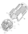
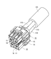
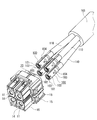
以下、図1~図7に示される電気コネクタ1に基づいて本発明を詳細に説明する。
電気コネクタ1は、ケーブル105の電線110の先端に接続されたコンタクト100を保持するハウジング10と、コンタクト100を係止して抜け止めするロックリング30と、ロックリング30をハウジング10に固定する押さえブロック50と、コンタクト100との係止を解除する向きにロックリング30を動作させる係止解除部材70と、ハウジング10と接続されその後端を覆うカバー90とを備える。電気コネクタ1は、図示しない相手側の電気コネクタと接続、離脱が可能とされる。
電気コネクタ1は、ケーブル105の電線110の先端に接続されたコンタクト100を保持するハウジング10と、コンタクト100を係止して抜け止めするロックリング30と、ロックリング30をハウジング10に固定する押さえブロック50と、コンタクト100との係止を解除する向きにロックリング30を動作させる係止解除部材70と、ハウジング10と接続されその後端を覆うカバー90とを備える。電気コネクタ1は、図示しない相手側の電気コネクタと接続、離脱が可能とされる。
ハウジング10は、合成樹脂を射出成形して作製されたものであり、前後方向に貫通する円筒状のキャビティ11を備える。キャビティ11は、上下方向に2列、幅方向に2列形成されている。各キャビティ11には後方からコンタクト100が挿入される。
キャビティ11は、前後方向の中央部にロックリング収容部12を、また、後方に押さえブロック収容部13を有している。ロックリング収容部12は、前方に行くに従って徐々に径が縮小される部分と、それよりも後方の径の等しい部分とからなる。また、押さえブロック収容部13は、ロックリング収容部12よりも開口径が大きく、かつ前後方向に径が等しくされている。
また、ハウジング10は、前端にキャビティ11の内方に向けて突出するリング状のコンタクト規制突起14を各キャビティ11に有している。コンタクト規制突起14にコンタクト100の前端を突き当てることにより、コンタクト100はキャビティ11内の正規位置に位置決めされる。
キャビティ11は、前後方向の中央部にロックリング収容部12を、また、後方に押さえブロック収容部13を有している。ロックリング収容部12は、前方に行くに従って徐々に径が縮小される部分と、それよりも後方の径の等しい部分とからなる。また、押さえブロック収容部13は、ロックリング収容部12よりも開口径が大きく、かつ前後方向に径が等しくされている。
また、ハウジング10は、前端にキャビティ11の内方に向けて突出するリング状のコンタクト規制突起14を各キャビティ11に有している。コンタクト規制突起14にコンタクト100の前端を突き当てることにより、コンタクト100はキャビティ11内の正規位置に位置決めされる。
ロックリング収容部12に収容されるロックリング30は、スリット32を挟んで円錐面上に配置される4枚のランス片31を有している。ハウジング10内でランスとして機能するランス片31は、後端が円筒状の基部33に連なり、また、前端面がコンタクト100の係止突起104と対向する係止面34を有する。ロックリング30はステンレス鋼等の金属板を打ち抜き及び曲げ加工により一体的に作製されたものであり、前方の径が縮小された部分にランス片31が、後方の径が等しい部分に基部33がそれぞれ配置されるようにロックリング収容部12に収容される。ロックリング30は、後述する押さえブロック50によって基部33がロックリング収容部12の内壁に押し付けられる。またランス片31が配置されるロックリング収容部12は、ランス片31が撓んで径方向外側に変位するのを許容する十分なスペースを有している。したがって、ランス片31は、ロックリング収容部12内において、基部33を固定端として径方向外側に撓み変形が可能である。
押さえブロック50は、合成樹脂を射出成形して作製されたものであり、連結部51により繋がる4つの本体52を有している。各本体52には、前後方向に貫通する円筒状の貫通孔54が形成されている。この貫通孔54内に、係止解除部材70の駆動部72が前後方向に相対移動可能に配置される。また、各本体52の前端には、貫通孔54と同軸状にリング状のランス押さえ部53が前方に向けて形成されている。
押さえブロック50は、本体52がハウジング10の押さえブロック収容部13に挿入、固定される。このとき、ランス押さえ部53は、ロックリング30の基部33の内径側に挿入され、かつ基部33を内径側からロックリング収容部12の内壁に向けて押し付ける。これにより、ロックリング30は、ハウジング10に保持される。
押さえブロック50は、本体52がハウジング10の押さえブロック収容部13に挿入、固定される。このとき、ランス押さえ部53は、ロックリング30の基部33の内径側に挿入され、かつ基部33を内径側からロックリング収容部12の内壁に向けて押し付ける。これにより、ロックリング30は、ハウジング10に保持される。
係止解除部材70は、合成樹脂を射出成形して作製されたものであり、連結部71で後端が繋がる4つの駆動部72を有している。駆動部72がランス片31の係止解除に関与する部分であり、連結部71は係止解除部材70を移動する際に作業者によって操作される操作部として機能する部分である。また、少なくとも駆動部72は、ロックリング30のランス片31よりも、径方向の剛性が高く作製されている。
駆動部72は、前後方向に貫通する貫通孔74を有する中空円筒状の部材であり、前端部外周には径方向外側に向けて突出する4つの係止突起73が等間隔で形成されている。係止突起73は、前端側の面が前方から後方に向けて緩やかな上り勾配の傾斜とされ、後端側の面は径方向に垂直とされている。
駆動部72の外径は、押さえブロック50のランス押さえ部53の内側に挿入可能なようにその内径よりも僅かに小さく設定されている。また、係止突起73の頂部の外径は、ランス押さえ部53の内径よりも大きく設定されている。したがって、駆動部72が押さえブロック50の貫通孔54内に挿入されると、係止突起73とランス押さえ部53とが干渉する関係にある。
駆動部72は、前後方向に貫通する貫通孔74を有する中空円筒状の部材であり、前端部外周には径方向外側に向けて突出する4つの係止突起73が等間隔で形成されている。係止突起73は、前端側の面が前方から後方に向けて緩やかな上り勾配の傾斜とされ、後端側の面は径方向に垂直とされている。
駆動部72の外径は、押さえブロック50のランス押さえ部53の内側に挿入可能なようにその内径よりも僅かに小さく設定されている。また、係止突起73の頂部の外径は、ランス押さえ部53の内径よりも大きく設定されている。したがって、駆動部72が押さえブロック50の貫通孔54内に挿入されると、係止突起73とランス押さえ部53とが干渉する関係にある。
カバー90は、前後方向に貫通するキャビティ91を有している。キャビティ91の前方側には、ロックリング30、押さえブロック50及び係止解除部材70が取り付けられたハウジング10の後方側を収容する。また、キャビティ91の後方側から電線110が挿入される。電線110の先端に設けられているコンタクト100は、カバー90のキャビティ91内において、ハウジング10に保持される。
例えば圧着により電線110に接続されるコンタクト100は、銅合金等の導電性材料からなる板材を円筒状に曲げ加工して形成されたものであり、その前端に図示しない相手側のコンタクトが挿入される開口101を有している。
コンタクト100の内部には、前記相手側のコンタクトと電気的に接続されるソケット状の接点部材102が配置されている。接点部材102は、その前後に形成されたコンタクト100の内側に向けて突出する位置決め突起103により、前後方向の位置が規制される。位置決め突起103は、例えば板材の状態でプレス加工することにより形成される。
コンタクト100の外周面には、コンタクト100の外側に向けて突出する係止突起104が形成されている。係止突起104とランス片31先端の係止面34とが係止されることにより、コンタクト100は抜け止めされる。係止突起104も、例えば板材の状態でプレス加工することにより形成される。係止突起104は、コンタクト100の外周面に等間隔で3箇所に形成されている。そうすることにより、ランス片31とコンタクト100の互いの軸方向周りの位置にかかわらず、4つのランス片31のいずれかの係止面34と3つの係止突起104のいずれかが対向して配置されるので、コンタクト100は確実に係止される。
コンタクト100の内部には、前記相手側のコンタクトと電気的に接続されるソケット状の接点部材102が配置されている。接点部材102は、その前後に形成されたコンタクト100の内側に向けて突出する位置決め突起103により、前後方向の位置が規制される。位置決め突起103は、例えば板材の状態でプレス加工することにより形成される。
コンタクト100の外周面には、コンタクト100の外側に向けて突出する係止突起104が形成されている。係止突起104とランス片31先端の係止面34とが係止されることにより、コンタクト100は抜け止めされる。係止突起104も、例えば板材の状態でプレス加工することにより形成される。係止突起104は、コンタクト100の外周面に等間隔で3箇所に形成されている。そうすることにより、ランス片31とコンタクト100の互いの軸方向周りの位置にかかわらず、4つのランス片31のいずれかの係止面34と3つの係止突起104のいずれかが対向して配置されるので、コンタクト100は確実に係止される。
ハウジング10にロックリング30、押さえブロック50及び係止解除部材70を取り付ける手順は以下の通りである。
押さえブロック50の貫通孔54の後端から係止解除部材70の駆動部72を挿入する。駆動部72先端の係止突起73の頂部の外径は押さえブロック50のランス押さえ部53の内径よりも大きいので係止突起73とランス押さえ部53とが干渉するが、さらに係止解除部材70を押し込むと、弾性変形により駆動部72の前端部分の径が縮小して、係止突起73がランス押さえ部53を通過する。ランス押さえ部53を通過すると、駆動部72の前端部分は弾性復帰する。係止解除部材70は、押さえブロック50に対して、係止突起73とランス押さえ部53とが突き当たる位置(最後端,第2の位置)と、連結部71と本体52とが突き当たる位置(最前端,第1の位置)との間で前後方向に進退が可能である。なお、係止突起73の前方側が傾斜面となっているので、後方から前方の向きには、係止突起73はランス押さえ部53を通過しやすい。しかし、係止突起73の後方側は垂直な面となっているので、係止解除部材70は、前方から後方の向きに移動すると、係止突起73はランス押さえ部53に突き当たり、ランス押さえ部53を通過しにくい。このように、ランス押さえ部53は、ロックリング30の基部33をハウジング10に押し付ける機能と、係止解除部材70の移動範囲を規制する機能とを併せ持つ。
押さえブロック50の貫通孔54の後端から係止解除部材70の駆動部72を挿入する。駆動部72先端の係止突起73の頂部の外径は押さえブロック50のランス押さえ部53の内径よりも大きいので係止突起73とランス押さえ部53とが干渉するが、さらに係止解除部材70を押し込むと、弾性変形により駆動部72の前端部分の径が縮小して、係止突起73がランス押さえ部53を通過する。ランス押さえ部53を通過すると、駆動部72の前端部分は弾性復帰する。係止解除部材70は、押さえブロック50に対して、係止突起73とランス押さえ部53とが突き当たる位置(最後端,第2の位置)と、連結部71と本体52とが突き当たる位置(最前端,第1の位置)との間で前後方向に進退が可能である。なお、係止突起73の前方側が傾斜面となっているので、後方から前方の向きには、係止突起73はランス押さえ部53を通過しやすい。しかし、係止突起73の後方側は垂直な面となっているので、係止解除部材70は、前方から後方の向きに移動すると、係止突起73はランス押さえ部53に突き当たり、ランス押さえ部53を通過しにくい。このように、ランス押さえ部53は、ロックリング30の基部33をハウジング10に押し付ける機能と、係止解除部材70の移動範囲を規制する機能とを併せ持つ。
次に、ロックリング30の基部33をランス押さえ部53の外側に嵌め込むことにより、ロックリング30を押さえブロック50に装着する。これにより、係止解除部材70の係止突起73は、ロックリング30の内側に配置される。
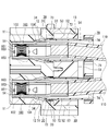
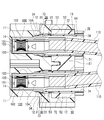
ロックリング30、押さえブロック50及び係止解除部材70からなる組立体は、ロックリング30が装着された側から、ハウジング10のキャビティ11に挿入される。押さえブロック50の本体52の前端面がキャビティ11の内壁面に突き当たる正規位置まで前記組立体を押し込むと、ロックリング30等のハウジング10への取り付けが完了する(図6)。
図6に示されるように、ハウジング10のキャビティ11に押さえブロック50が固定される。押さえブロック50の貫通孔54内には、係止解除部材70の駆動部72が配置される。係止突起73を含む駆動部72の前方部分は押さえブロック50よりも前方に突出し、係止突起73はランス片31の内側に配置される。また、駆動部72の後方部分はキャビティ11を貫通して押さえブロック50よりも後方に突出している。つまり、ハウジング10の後端からランス片31の位置にかけて、ハウジング10のキャビティ11(押さえブロック50の貫通孔54)の内壁とコンタクト100との間に進退経路が形成され、駆動部72はこの経路に進退可能に配置されている。そして、ランス片31まで係止突起73が到達する駆動部72をその経路に配設したので、連結部71を前方に移動させるだけで、係止を解除する向きにランス片31を変位させることができる。
次に、電線110(コンタクト100)のハウジング10への取付は、以下のようにして行われる。なお、カバー90のキャビティ91を貫通して、コンタクト100がカバー90の外部に露出している状態で、電線110の接続が行われる。
電線110の端末に接続した各コンタクト100を係止解除部材70の貫通孔74の後端から挿入する。コンタクト100は、その前端がハウジング10のコンタクト規制突起14に突き当たる所定深さまで挿入される。その過程で、コンタクト100の外周に形成されている係止突起104が、ロックリング30のランス片31を外側に押し広げてランス片31を通過し、ランス片31が元の状態に復帰する。そうして、係止突起104とランス片31の前端にある係止面34とが対向して配置されることにより、コンタクト100を引き抜こうとしても、係止突起104がランス片31の係止面34に係止され、コンタクト100は抜け止めされる。
電線110の端末に接続した各コンタクト100を係止解除部材70の貫通孔74の後端から挿入する。コンタクト100は、その前端がハウジング10のコンタクト規制突起14に突き当たる所定深さまで挿入される。その過程で、コンタクト100の外周に形成されている係止突起104が、ロックリング30のランス片31を外側に押し広げてランス片31を通過し、ランス片31が元の状態に復帰する。そうして、係止突起104とランス片31の前端にある係止面34とが対向して配置されることにより、コンタクト100を引き抜こうとしても、係止突起104がランス片31の係止面34に係止され、コンタクト100は抜け止めされる。
電線110を取り付けた後、ハウジング10の後側をカバー90のキャビティ91の正規位置に挿入する。そうすると、ハウジング10の側面に設けられた抜け止め突起15がカバー90の係止溝92に係止され、ハウジング10とカバー90とがロック状態とされる。
電気コネクタ1の使用状態、つまりコンタクト100が抜け止めされた状態では、図6に示されるように、係止解除部材70を最後端(第2の位置)まで移動させる。
電気コネクタ1の使用状態、つまりコンタクト100が抜け止めされた状態では、図6に示されるように、係止解除部材70を最後端(第2の位置)まで移動させる。
電線110をハウジング10に取り付けた後に、例えばメンテナンスのためにハウジング10からコンタクト100を取り外すことがある。その場合は、係止解除部材70を操作できるように、ハウジング10とカバー90とのロック状態を解除し、カバー90を取り外す。次に、最後端(第2の位置)に引き出されていた係止解除部材70の操作部である連結部71を前方に向けて押し込む。この過程で、駆動部72の剛性がランス片31よりも高いので、前方に移動してきた係止突起73によりロックリング30のランス片31がロックリング収容部12の内壁に向けて押され、ランス片31は径方向外側に向けて、つまり係止を解除する向きに撓んで変位する。係止解除部材70を、連結部71が押さえブロック50の本体52に突き当たるまで、つまり最前端(第1の位置)まで押し込むと、ランス片31の変位が最大となり、ランス片31の前端で囲まれる略円形領域の径が、コンタクト100の係止突起104の頂部の径よりも大きくなる。これにより、抜け止めが解除される(図7)。最前端に係止解除部材70を位置させたままで、電線110を後方へ引っ張ることで、コンタクト100をハウジング10から取り出すことができる。コンタクト100を取り外した後も最前端に係止解除部材70を位置させたままにしておけば、次にコンタクト100をハウジング10に挿入する作業が容易である。係止解除部材70は、係止突起73とランス片31の摩擦係合により、最前端に留まろうとする。なお、最初にコンタクト100をハウジング10に挿入する際に、係止解除部材70を最前端に位置させて係止状態を解除しておいてもよい。
以上説明したように電気コネクタ1によれば、ハウジング10に取り付けられている係止解除部材70を操作することにより、ランス片31の係止状態を解除できるので、取り外し用の冶具を用いることなくコンタクト100の取り外しができる。しかも、電気コネクタ1によれば、係止解除部材70を最後端(第2の位置)から最前端(第1の位置)へ移動させるのみでランス片31の係止状態を解除できるので、コンタクト100の取り外しの作業効率がよい。また逆に、係止解除部材70を最前端(第1の位置)から最後端(第2の位置)へ移動させるのみでランス片31を係止状態にできるので、コンタクト100の取り付けの作業効率もよい。
また電気コネクタ1の係止解除の作業は、電気コネクタ1の後方、つまり電線110の導出側で連結部71を前方に向けて押し込むものである。したがって、引続き行なわれる電線110の引き抜きとともに一連の作業が電線110の導出側だけで行なえるので、コンタクト100の取り外しの作業性が優れる。
さらに電気コネクタ1は、係止解除部材70、特に作業者が係止解除部材70を移動させる際に操作する連結部71がカバー90の内部に収容されているので、係止解除部材70の不用意な動作を防ぎ、ランス片31の係止状態が使用時に解除されることがない。
また電気コネクタ1の係止解除の作業は、電気コネクタ1の後方、つまり電線110の導出側で連結部71を前方に向けて押し込むものである。したがって、引続き行なわれる電線110の引き抜きとともに一連の作業が電線110の導出側だけで行なえるので、コンタクト100の取り外しの作業性が優れる。
さらに電気コネクタ1は、係止解除部材70、特に作業者が係止解除部材70を移動させる際に操作する連結部71がカバー90の内部に収容されているので、係止解除部材70の不用意な動作を防ぎ、ランス片31の係止状態が使用時に解除されることがない。
電気コネクタ1は、4つの駆動部72が連結部71を介して一体化されているので、係止解除部材70を操作することにより、4つのランス片31の係止状態を一度に解除できる。ただし、本発明は、複数の駆動部72を独立して設けることにより、ランス片31を一つずつその係止状態を解除できるようにしてもよい。もちろん、電線110が一本だけ接続される電気コネクタ1について適用することもできる。
これ以外にも、本発明の主旨を逸脱しない限り、上記実施の形態で挙げた構成を取捨選択し、他の構成に適宜変更することが可能である。例えば、ランスとして機能するロックリング30(ランス片31)は、この形態に限るものでなく、ハウジング10に一体的に形成されるランスについて本発明を適用することもできる。また例えば、コンタクト100についても、雄型コンタクト等の他の形態であっても本発明を適用できる。
これ以外にも、本発明の主旨を逸脱しない限り、上記実施の形態で挙げた構成を取捨選択し、他の構成に適宜変更することが可能である。例えば、ランスとして機能するロックリング30(ランス片31)は、この形態に限るものでなく、ハウジング10に一体的に形成されるランスについて本発明を適用することもできる。また例えば、コンタクト100についても、雄型コンタクト等の他の形態であっても本発明を適用できる。
1…電気コネクタ、
10…ハウジング、11…キャビティ、12…ロックリング収容部、13…押さえブロック収容部、14…コンタクト規制突起、15…抜け止め突起
30…ロックリング、31…ランス片、32…スリット、33…基部、34…係止面、
50…押さえブロック、51…連結部、52…本体、53…ランス押さえ部、54…貫通孔、
70…係止解除部材、71…連結部、72…駆動部、73…係止突起、74…貫通孔、
90…カバー、91…キャビティ、92…係止溝
100…コンタクト、101…開口、102…接点部材、103…位置決め突起、104…係止突起、
105…ケーブル、110…電線
10…ハウジング、11…キャビティ、12…ロックリング収容部、13…押さえブロック収容部、14…コンタクト規制突起、15…抜け止め突起
30…ロックリング、31…ランス片、32…スリット、33…基部、34…係止面、
50…押さえブロック、51…連結部、52…本体、53…ランス押さえ部、54…貫通孔、
70…係止解除部材、71…連結部、72…駆動部、73…係止突起、74…貫通孔、
90…カバー、91…キャビティ、92…係止溝
100…コンタクト、101…開口、102…接点部材、103…位置決め突起、104…係止突起、
105…ケーブル、110…電線
Claims (6)
- 相手側コンタクトと電気的に接続されるコンタクトと、
前記コンタクトを収容するキャビティが形成されるハウジングと、
前記キャビティ内に設けられ、前記コンタクトを係止して前記キャビティから抜け止めするランスと、
前記ハウジングに進退可能に取り付けられ、後方から前方に向けて移動させると、前記コンタクトの係止を解除する向きに前記ランスを変位させる係止解除部材と、
を備えることを特徴とする電気コネクタ。 - 前記ハウジングの後端から前記ランスの位置にかけて貫通する経路が前記キャビティ内に形成され、前記経路内を前記係止解除部材が進退することを特徴とする請求項1に記載の電気コネクタ。
- 前記係止解除部材は、前記係止解除に関与する駆動部と、前記駆動部に連なり前記移動の際に操作される操作部とを備え、
前記駆動部が前記経路を進退することを特徴とする請求項2に記載の電気コネクタ。 - 前記係止解除部材は、前方側の第1の位置と後方側の第2の位置との間で進退可能に前記ハウジングに取り付けられ、
前記係止解除部材が前記第1の位置にあるときには、前記係止解除部材から前記ランスへ負荷を与えることにより、前記コンタクトの係止を解除する向きに前記ランスを変位させ、
前記係止解除部材が前記第2の位置にあるときには、前記係止解除部材から前記ランスへの負荷が解かれることにより、前記ランスが前記コンタクトを係止することを特徴とする請求項1~3のいずれかに記載の電気コネクタ。 - 前記電気コネクタは、複数の前記コンタクトと、
複数の前記コンタクトを係止して前記キャビティから抜け止めする複数の前記ランスと、
一体化された複数の前記係止解除部材と、
を備えることを特徴とする請求項1~3のいずれかに記載の電気コネクタ。 - 前記ハウジングに取り付けられる、前記係止解除部材を覆うカバーをさらに備えることを特徴とする請求項1~3のいずれかに記載の電気コネクタ。
Priority Applications (2)
| Application Number | Priority Date | Filing Date | Title |
|---|---|---|---|
| CN2009801325347A CN102124612B (zh) | 2008-08-20 | 2009-06-23 | 电连接器 |
| DE112009001980.3T DE112009001980B4 (de) | 2008-08-20 | 2009-06-23 | Elektrischer Verbinder |
Applications Claiming Priority (2)
| Application Number | Priority Date | Filing Date | Title |
|---|---|---|---|
| JP2008211520A JP5046395B2 (ja) | 2008-08-20 | 2008-08-20 | 電気コネクタ |
| JP2008-211520 | 2008-08-20 |
Publications (1)
| Publication Number | Publication Date |
|---|---|
| WO2010021074A1 true WO2010021074A1 (ja) | 2010-02-25 |
Family
ID=41706968
Family Applications (1)
| Application Number | Title | Priority Date | Filing Date |
|---|---|---|---|
| PCT/JP2009/002869 Ceased WO2010021074A1 (ja) | 2008-08-20 | 2009-06-23 | 電気コネクタ |
Country Status (4)
| Country | Link |
|---|---|
| JP (1) | JP5046395B2 (ja) |
| CN (1) | CN102124612B (ja) |
| DE (1) | DE112009001980B4 (ja) |
| WO (1) | WO2010021074A1 (ja) |
Families Citing this family (4)
| Publication number | Priority date | Publication date | Assignee | Title |
|---|---|---|---|---|
| JP6125891B2 (ja) * | 2013-05-07 | 2017-05-10 | 矢崎総業株式会社 | 端子金具の保持構造 |
| JP6386138B1 (ja) | 2017-07-14 | 2018-09-05 | 日本航空電子工業株式会社 | コネクタ |
| JP6423053B1 (ja) | 2017-07-14 | 2018-11-14 | 日本航空電子工業株式会社 | コネクタ |
| JP2020193668A (ja) * | 2019-05-28 | 2020-12-03 | 本田技研工業株式会社 | ベアリングの取り外し方法 |
Citations (1)
| Publication number | Priority date | Publication date | Assignee | Title |
|---|---|---|---|---|
| JP2008052974A (ja) * | 2006-08-23 | 2008-03-06 | Yazaki Corp | コネクタ |
Family Cites Families (8)
| Publication number | Priority date | Publication date | Assignee | Title |
|---|---|---|---|---|
| GB1180954A (en) | 1966-11-29 | 1970-02-11 | Fernand Georges Bac | An Electrical Connector with Removable Contacts. |
| US3808590A (en) | 1973-02-27 | 1974-04-30 | Bendix Corp | Contact retention and removal assembly for a multi-pin electrical |
| JPH035098Y2 (ja) * | 1986-04-21 | 1991-02-08 | ||
| US5643009A (en) | 1996-02-26 | 1997-07-01 | The Whitaker Corporation | Electrical connector having a pivot lock |
| EP1619760B1 (en) * | 2003-01-16 | 2007-09-19 | Sumitomo Wiring Systems, Ltd. | A jig and a method for withdrawing a terminal in a connector |
| JP4069757B2 (ja) | 2003-02-14 | 2008-04-02 | 住友電装株式会社 | コネクタ |
| US7059879B2 (en) * | 2004-05-20 | 2006-06-13 | Hubbell Incorporated | Electrical connector having a piston-contact element |
| JP2008123776A (ja) | 2006-11-10 | 2008-05-29 | Sumitomo Wiring Syst Ltd | コネクタ及び端子抜き方法 |
-
2008
- 2008-08-20 JP JP2008211520A patent/JP5046395B2/ja active Active
-
2009
- 2009-06-23 CN CN2009801325347A patent/CN102124612B/zh active Active
- 2009-06-23 DE DE112009001980.3T patent/DE112009001980B4/de active Active
- 2009-06-23 WO PCT/JP2009/002869 patent/WO2010021074A1/ja not_active Ceased
Patent Citations (1)
| Publication number | Priority date | Publication date | Assignee | Title |
|---|---|---|---|---|
| JP2008052974A (ja) * | 2006-08-23 | 2008-03-06 | Yazaki Corp | コネクタ |
Also Published As
| Publication number | Publication date |
|---|---|
| DE112009001980B4 (de) | 2020-06-25 |
| CN102124612B (zh) | 2013-08-21 |
| JP5046395B2 (ja) | 2012-10-10 |
| CN102124612A (zh) | 2011-07-13 |
| JP2010049866A (ja) | 2010-03-04 |
| DE112009001980T5 (de) | 2012-01-26 |
Similar Documents
| Publication | Publication Date | Title |
|---|---|---|
| JP4387438B2 (ja) | レバー式コネクタ | |
| JP4468465B2 (ja) | レバー式コネクタ | |
| JP4405564B2 (ja) | レバー式コネクタ | |
| US9270055B2 (en) | Connector with vibratory connection feedback | |
| WO2010032392A1 (ja) | 電気コネクタ | |
| JP5917171B2 (ja) | 光ファイバコネクタ | |
| WO2010021074A1 (ja) | 電気コネクタ | |
| KR20170070997A (ko) | 커넥터의 록킹 구조 및 커넥터 | |
| JP5172871B2 (ja) | レバー式コネクタ | |
| WO2014084025A1 (ja) | 端子抜き治具 | |
| JP5370254B2 (ja) | コネクタ | |
| JPH0950858A (ja) | コネクタの嵌合構造 | |
| JP2007317442A (ja) | コネクタ | |
| JP2016213084A (ja) | コネクタ | |
| JP6077797B2 (ja) | 光コネクタ | |
| JP6535396B1 (ja) | 光コネクタ及び光コネクタの接続方法 | |
| JP2017117625A (ja) | コネクタ及び待ち受けコネクタ | |
| JP6721494B2 (ja) | コネクタ | |
| JP2005085615A (ja) | リテーナ付き端子収容部材、及び治具 | |
| JP2009205906A (ja) | コネクタ | |
| JP2020187850A (ja) | 端子抜き取り治具 | |
| JP2005166599A (ja) | ヒューズボックスの電線接続構造 | |
| JP2013069487A (ja) | コネクタ | |
| JP2019114363A (ja) | 端子抜き取り治具 | |
| JP6767354B2 (ja) | 端子抜き取り治具 |
Legal Events
| Date | Code | Title | Description |
|---|---|---|---|
| WWE | Wipo information: entry into national phase |
Ref document number: 200980132534.7 Country of ref document: CN |
|
| 121 | Ep: the epo has been informed by wipo that ep was designated in this application |
Ref document number: 09808010 Country of ref document: EP Kind code of ref document: A1 |
|
| 122 | Ep: pct application non-entry in european phase |
Ref document number: 09808010 Country of ref document: EP Kind code of ref document: A1 |