WO2010001878A2 - Aimant résistant à la corrosion et son procédé de production - Google Patents
Aimant résistant à la corrosion et son procédé de production Download PDFInfo
- Publication number
- WO2010001878A2 WO2010001878A2 PCT/JP2009/061913 JP2009061913W WO2010001878A2 WO 2010001878 A2 WO2010001878 A2 WO 2010001878A2 JP 2009061913 W JP2009061913 W JP 2009061913W WO 2010001878 A2 WO2010001878 A2 WO 2010001878A2
- Authority
- WO
- WIPO (PCT)
- Prior art keywords
- magnet
- chemical conversion
- corrosion
- conversion film
- atomic
- Prior art date
Links
Images

Classifications
-
- H—ELECTRICITY
- H01—ELECTRIC ELEMENTS
- H01F—MAGNETS; INDUCTANCES; TRANSFORMERS; SELECTION OF MATERIALS FOR THEIR MAGNETIC PROPERTIES
- H01F41/00—Apparatus or processes specially adapted for manufacturing or assembling magnets, inductances or transformers; Apparatus or processes specially adapted for manufacturing materials characterised by their magnetic properties
- H01F41/02—Apparatus or processes specially adapted for manufacturing or assembling magnets, inductances or transformers; Apparatus or processes specially adapted for manufacturing materials characterised by their magnetic properties for manufacturing cores, coils, or magnets
- H01F41/0253—Apparatus or processes specially adapted for manufacturing or assembling magnets, inductances or transformers; Apparatus or processes specially adapted for manufacturing materials characterised by their magnetic properties for manufacturing cores, coils, or magnets for manufacturing permanent magnets
- H01F41/026—Apparatus or processes specially adapted for manufacturing or assembling magnets, inductances or transformers; Apparatus or processes specially adapted for manufacturing materials characterised by their magnetic properties for manufacturing cores, coils, or magnets for manufacturing permanent magnets protecting methods against environmental influences, e.g. oxygen, by surface treatment
-
- B—PERFORMING OPERATIONS; TRANSPORTING
- B22—CASTING; POWDER METALLURGY
- B22F—WORKING METALLIC POWDER; MANUFACTURE OF ARTICLES FROM METALLIC POWDER; MAKING METALLIC POWDER; APPARATUS OR DEVICES SPECIALLY ADAPTED FOR METALLIC POWDER
- B22F3/00—Manufacture of workpieces or articles from metallic powder characterised by the manner of compacting or sintering; Apparatus specially adapted therefor ; Presses and furnaces
- B22F3/24—After-treatment of workpieces or articles
-
- C—CHEMISTRY; METALLURGY
- C22—METALLURGY; FERROUS OR NON-FERROUS ALLOYS; TREATMENT OF ALLOYS OR NON-FERROUS METALS
- C22C—ALLOYS
- C22C33/00—Making ferrous alloys
- C22C33/02—Making ferrous alloys by powder metallurgy
- C22C33/0257—Making ferrous alloys by powder metallurgy characterised by the range of the alloying elements
- C22C33/0278—Making ferrous alloys by powder metallurgy characterised by the range of the alloying elements with at least one alloying element having a minimum content above 5%
-
- C—CHEMISTRY; METALLURGY
- C22—METALLURGY; FERROUS OR NON-FERROUS ALLOYS; TREATMENT OF ALLOYS OR NON-FERROUS METALS
- C22C—ALLOYS
- C22C38/00—Ferrous alloys, e.g. steel alloys
-
- C—CHEMISTRY; METALLURGY
- C23—COATING METALLIC MATERIAL; COATING MATERIAL WITH METALLIC MATERIAL; CHEMICAL SURFACE TREATMENT; DIFFUSION TREATMENT OF METALLIC MATERIAL; COATING BY VACUUM EVAPORATION, BY SPUTTERING, BY ION IMPLANTATION OR BY CHEMICAL VAPOUR DEPOSITION, IN GENERAL; INHIBITING CORROSION OF METALLIC MATERIAL OR INCRUSTATION IN GENERAL
- C23C—COATING METALLIC MATERIAL; COATING MATERIAL WITH METALLIC MATERIAL; SURFACE TREATMENT OF METALLIC MATERIAL BY DIFFUSION INTO THE SURFACE, BY CHEMICAL CONVERSION OR SUBSTITUTION; COATING BY VACUUM EVAPORATION, BY SPUTTERING, BY ION IMPLANTATION OR BY CHEMICAL VAPOUR DEPOSITION, IN GENERAL
- C23C22/00—Chemical surface treatment of metallic material by reaction of the surface with a reactive liquid, leaving reaction products of surface material in the coating, e.g. conversion coatings, passivation of metals
- C23C22/05—Chemical surface treatment of metallic material by reaction of the surface with a reactive liquid, leaving reaction products of surface material in the coating, e.g. conversion coatings, passivation of metals using aqueous solutions
- C23C22/06—Chemical surface treatment of metallic material by reaction of the surface with a reactive liquid, leaving reaction products of surface material in the coating, e.g. conversion coatings, passivation of metals using aqueous solutions using aqueous acidic solutions with pH less than 6
- C23C22/34—Chemical surface treatment of metallic material by reaction of the surface with a reactive liquid, leaving reaction products of surface material in the coating, e.g. conversion coatings, passivation of metals using aqueous solutions using aqueous acidic solutions with pH less than 6 containing fluorides or complex fluorides
-
- H—ELECTRICITY
- H01—ELECTRIC ELEMENTS
- H01F—MAGNETS; INDUCTANCES; TRANSFORMERS; SELECTION OF MATERIALS FOR THEIR MAGNETIC PROPERTIES
- H01F1/00—Magnets or magnetic bodies characterised by the magnetic materials therefor; Selection of materials for their magnetic properties
- H01F1/01—Magnets or magnetic bodies characterised by the magnetic materials therefor; Selection of materials for their magnetic properties of inorganic materials
- H01F1/03—Magnets or magnetic bodies characterised by the magnetic materials therefor; Selection of materials for their magnetic properties of inorganic materials characterised by their coercivity
- H01F1/032—Magnets or magnetic bodies characterised by the magnetic materials therefor; Selection of materials for their magnetic properties of inorganic materials characterised by their coercivity of hard-magnetic materials
- H01F1/04—Magnets or magnetic bodies characterised by the magnetic materials therefor; Selection of materials for their magnetic properties of inorganic materials characterised by their coercivity of hard-magnetic materials metals or alloys
- H01F1/047—Alloys characterised by their composition
- H01F1/053—Alloys characterised by their composition containing rare earth metals
- H01F1/055—Alloys characterised by their composition containing rare earth metals and magnetic transition metals, e.g. SmCo5
- H01F1/057—Alloys characterised by their composition containing rare earth metals and magnetic transition metals, e.g. SmCo5 and IIIa elements, e.g. Nd2Fe14B
- H01F1/0571—Alloys characterised by their composition containing rare earth metals and magnetic transition metals, e.g. SmCo5 and IIIa elements, e.g. Nd2Fe14B in the form of particles, e.g. rapid quenched powders or ribbon flakes
- H01F1/0575—Alloys characterised by their composition containing rare earth metals and magnetic transition metals, e.g. SmCo5 and IIIa elements, e.g. Nd2Fe14B in the form of particles, e.g. rapid quenched powders or ribbon flakes pressed, sintered or bonded together
- H01F1/0577—Alloys characterised by their composition containing rare earth metals and magnetic transition metals, e.g. SmCo5 and IIIa elements, e.g. Nd2Fe14B in the form of particles, e.g. rapid quenched powders or ribbon flakes pressed, sintered or bonded together sintered
-
- H—ELECTRICITY
- H01—ELECTRIC ELEMENTS
- H01F—MAGNETS; INDUCTANCES; TRANSFORMERS; SELECTION OF MATERIALS FOR THEIR MAGNETIC PROPERTIES
- H01F7/00—Magnets
- H01F7/02—Permanent magnets [PM]
- H01F7/0205—Magnetic circuits with PM in general
- H01F7/0221—Mounting means for PM, supporting, coating, encapsulating PM
-
- B—PERFORMING OPERATIONS; TRANSPORTING
- B22—CASTING; POWDER METALLURGY
- B22F—WORKING METALLIC POWDER; MANUFACTURE OF ARTICLES FROM METALLIC POWDER; MAKING METALLIC POWDER; APPARATUS OR DEVICES SPECIALLY ADAPTED FOR METALLIC POWDER
- B22F3/00—Manufacture of workpieces or articles from metallic powder characterised by the manner of compacting or sintering; Apparatus specially adapted therefor ; Presses and furnaces
- B22F3/24—After-treatment of workpieces or articles
- B22F2003/241—Chemical after-treatment on the surface
-
- B—PERFORMING OPERATIONS; TRANSPORTING
- B22—CASTING; POWDER METALLURGY
- B22F—WORKING METALLIC POWDER; MANUFACTURE OF ARTICLES FROM METALLIC POWDER; MAKING METALLIC POWDER; APPARATUS OR DEVICES SPECIALLY ADAPTED FOR METALLIC POWDER
- B22F2207/00—Aspects of the compositions, gradients
- B22F2207/01—Composition gradients
-
- C—CHEMISTRY; METALLURGY
- C22—METALLURGY; FERROUS OR NON-FERROUS ALLOYS; TREATMENT OF ALLOYS OR NON-FERROUS METALS
- C22C—ALLOYS
- C22C2202/00—Physical properties
- C22C2202/02—Magnetic
-
- Y—GENERAL TAGGING OF NEW TECHNOLOGICAL DEVELOPMENTS; GENERAL TAGGING OF CROSS-SECTIONAL TECHNOLOGIES SPANNING OVER SEVERAL SECTIONS OF THE IPC; TECHNICAL SUBJECTS COVERED BY FORMER USPC CROSS-REFERENCE ART COLLECTIONS [XRACs] AND DIGESTS
- Y10—TECHNICAL SUBJECTS COVERED BY FORMER USPC
- Y10T—TECHNICAL SUBJECTS COVERED BY FORMER US CLASSIFICATION
- Y10T428/00—Stock material or miscellaneous articles
- Y10T428/12—All metal or with adjacent metals
- Y10T428/12465—All metal or with adjacent metals having magnetic properties, or preformed fiber orientation coordinate with shape
Definitions
- the present invention relates to an R—Fe—B sintered magnet imparted with corrosion resistance and a method for producing the same.
- R-Fe-B based sintered magnets represented by Nd-Fe-B based sintered magnets have high magnetic properties and are used in various fields today.
- the R—Fe—B based sintered magnet contains a highly reactive rare earth metal: R, it is easily oxidized and corroded in the atmosphere, and when used without any surface treatment, a slight amount of acid is present. Corrosion progresses from the surface due to the presence of alkali, moisture, and the like, and rust is generated, which causes deterioration and variation in magnet characteristics.
- the rust may be scattered to contaminate peripheral components.
- Patent Document 1 describes a method of forming a phosphate coating as a chemical coating on the surface of a magnet, and this method is a simple rust prevention method for easily imparting necessary corrosion resistance to a magnet.
- Japanese Patent Publication No.4-22008 discloses a method for imparting corrosion resistance to an R—Fe—B based sintered magnet.
- the method of directly forming a chemical conversion film on the surface of an R—Fe—B based sintered magnet as described in Patent Document 1 does not leave the area of the simple anticorrosion method so far. In an environment that tends to cause susceptibility, magnetic powder is likely to fall off and the magnet is easily cracked. Therefore, it has been desired to develop a method for forming a chemical conversion film with better corrosion resistance. Therefore, the present invention provides a chemical conversion film having a higher corrosion resistance than a conventional chemical conversion film such as a phosphate film.
- An object of the present invention is to provide a sintered magnet and a manufacturing method thereof.
- the corrosion-resistant magnet of the present invention made in view of the above points is characterized in that, as described in claim 1, Zr as a constituent element is formed on the surface of an R—Fe—B sintered magnet (R is a rare earth element containing at least Nd). It has a chemical conversion film (but not phosphorus) that contains at least Nd, fluorine, and oxygen.
- R is a rare earth element containing at least Nd
- It has a chemical conversion film (but not phosphorus) that contains at least Nd, fluorine, and oxygen.
- the corrosion-resistant magnet according to claim 2 is the corrosion-resistant magnet according to claim 1, wherein the chemical conversion film further contains Fe as a constituent element.
- the corrosion-resistant magnet according to claim 3 is the corrosion-resistant magnet according to claim 2, wherein the chemical conversion film has a thickness of 10 nm to 150 nm.
- the corrosion-resistant magnet according to claim 4 is the corrosion-resistant magnet according to claim 2, wherein the former is more than the latter when the Zr content in the outer surface side half region and the magnet side half region of the thickness of the chemical conversion film is compared. It is characterized by many.
- the corrosion-resistant magnet according to claim 5 is characterized in that, in the corrosion-resistant magnet according to claim 4, the maximum value of the Zr content in the thickness direction of the outer surface side half region is 5 atomic% to 30 atomic%.
- the corrosion-resistant magnet according to claim 6 is characterized in that in the corrosion-resistant magnet according to claim 2, the Nd content and fluorine content of the chemical conversion film are higher in the upper part of the grain boundary phase than in the upper part of the main phase on the magnet surface.
- the corrosion-resistant magnet according to claim 7 is the corrosion-resistant magnet according to claim 6, wherein the maximum fluorine content in the thickness direction at the upper part of the grain boundary phase on the surface of the conversion coating magnet is 1 atomic% to 5 atomic%. It is characterized by that.
- the corrosion-resistant magnet according to claim 8 is the corrosion-resistant magnet according to claim 2, characterized in that it has a resin coating on the surface of the chemical conversion coating.
- the corrosion-resistant magnet according to claim 9 is the corrosion-resistant magnet according to claim 1, wherein the magnet has a layer composed of a compound containing Nd and oxygen on the surface thereof.
- the corrosion-resistant magnet according to claim 10 is the corrosion-resistant magnet according to claim 9, wherein the chemical conversion film has a thickness of 10 nm to 150 nm.
- the corrosion-resistant magnet according to claim 11 is characterized in that, in the corrosion-resistant magnet according to claim 9, the maximum value of the Zr content in the thickness direction of the chemical conversion film is 10 atom% to 20 atom%.
- a corrosion-resistant magnet according to claim 12 is the corrosion-resistant magnet according to claim 9, characterized in that the surface of the chemical conversion film has a resin film.
- Zr, Nd, Fe as constituent elements are formed on the surface of an R—Fe—B based sintered magnet (R is a rare earth element containing at least Nd). And a chemical conversion film containing at least fluorine and oxygen (but not containing phosphorus).
- the R—Fe—B based sintered magnet (R is a rare earth element containing at least Nd) is in a temperature range of 450 ° C. to 900 ° C.
- a chemical conversion film (but not containing phosphorus) containing at least Zr, Nd, fluorine, and oxygen as constituent elements is formed on the surface.
- a manufacturing method according to a fifteenth aspect is characterized in that, in the manufacturing method according to the fourteenth aspect, a magnet is accommodated in a heat-resistant box and heat treatment is performed.
- an R—Fe—B based sintered magnet having on its surface a chemical conversion film having better corrosion resistance than a conventional chemical conversion film such as a phosphate film, and a method for producing the same.
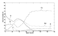
- FIG. 1 It is a chart which shows the result of the depth direction analysis of the upper part of the main phase by the Auger spectroscopy of the chemical conversion film in Example 1.
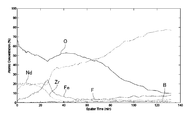
- FIG. It is a chart which shows the result of the depth direction analysis of the upper part of a grain-boundary phase similarly.
- the corrosion-resistant magnet according to the present invention is a chemical conversion coating containing at least Zr, Nd, fluorine and oxygen as constituent elements on the surface of an R—Fe—B based sintered magnet (R is a rare earth element containing at least Nd). It does not contain) directly (in other words, “without any other coating”).
- R—Fe—B based sintered magnet R is a rare earth element containing at least Nd
- R—Fe—B based sintered magnet may be simply referred to as “R—Fe—B based sintered magnet” or “magnet”.
- the R—Fe—B sintered magnet (R is a rare earth element containing at least Nd) to be treated in the present invention is adjusted to a predetermined dimension by, for example, surface processing such as cutting or grinding.
- the corrosion-resistant magnet of the present invention includes a corrosion-resistant magnet (first aspect) formed by forming a predetermined chemical conversion film on the surface thereof without performing a special artificial operation on the magnet to be processed in advance. After the magnet to be processed is subjected to a predetermined heat treatment, it is roughly classified into a corrosion-resistant magnet (second embodiment) formed by forming a predetermined chemical conversion film on the surface thereof.
- Corrosion-resistant magnet formed by forming a predetermined chemical conversion film on the surface thereof without subjecting the magnet to be processed in advance to a special artificial operation.
- at least Fe is contained (Nd and Fe are elements derived from the constituent components of the magnet).
- R—Fe—B sintered magnet R is a rare earth element containing at least Nd
- a chemical conversion film but not phosphorus containing at least Zr, Nd, Fe, fluorine and oxygen as constituent elements is formed.
- Examples of the method include a method in which an aqueous solution containing at least Zr and fluorine is used as a treatment liquid, applied to the surface of the magnet, and then dried.
- a compound containing Zr and fluorine such as fluorozirconic acid (H 2 ZrF 6 ), alkali metal salt, alkaline earth metal salt or ammonium salt of fluorozirconic acid is dissolved in water. What was prepared (furhydrofluoric acid etc. may be further added) is mentioned.
- the Zr content of the treatment liquid is preferably 1 ppm to 2000 ppm in terms of metal, and more preferably 10 ppm to 1000 ppm.
- the content is less than 1 ppm, the chemical conversion film may not be formed. If the content is more than 2000 ppm, the cost may increase. Further, the fluorine content of the treatment liquid is preferably 10 ppm to 10,000 ppm in terms of fluorine concentration, and more preferably 50 ppm to 5000 ppm. If the content is less than 10 ppm, the surface of the magnet may not be etched efficiently. If the content is more than 10000 ppm, the etching rate may be higher than the film formation rate, and it may be difficult to form a uniform film.
- the treatment liquid contains zirconium tetrachloride, Zr compounds containing no fluorine such as Zr sulfate and nitrate, and Zr such as hydrofluoric acid, ammonium fluoride, ammonium hydrogen fluoride, sodium fluoride, and sodium hydrogen fluoride. It may be prepared by dissolving a fluorine compound not contained in water.
- the treatment liquid may or may not contain a supply source of Nd and Fe that are constituent elements of the chemical conversion coating. These elements are eluted from the magnet by the surface of the R—Fe—B sintered magnet (R is a rare earth element containing at least Nd) during the chemical conversion treatment, and are taken into the chemical conversion film. is there.
- the pH of the treatment liquid is desirably adjusted to 1-6. This is because if the pH is less than 1, the surface of the magnet may be excessively etched, and if it exceeds 6, the stability of the treatment liquid may be affected.
- the treatment liquid has improved chemical conversion reactivity, improved stability of the treatment liquid, improved adhesion of the chemical conversion film to the surface of the magnet, and adhesion used when incorporating the magnet into a component.
- Organic acids such as tannic acid, oxidizing agents (hydrogen peroxide, chloric acid and its salts, nitrous acid and its salts, nitric acid and its salts, tungstic acid and its salts, Acid or a salt thereof), a water-soluble polyamide, a water-soluble resin such as polyallylamine, and the like may be added.
- the treatment liquid may be prepared as needed.
- An example of a commercially available processing solution that can be used in the present invention is Pulseed 1000 (trade name) prepared from Palceed 1000MA and AD-4990 provided by Nippon Parkerizing.
- the temperature of the treatment liquid is desirably 20 ° C. to 80 ° C. This is because if the temperature is less than 20 ° C, the reaction may not proceed, and if it exceeds 80 ° C, the stability of the treatment liquid may be affected.
- the treatment time is usually 10 seconds to 10 minutes.
- the temperature of the drying process is less than 50 ° C., it may not be sufficiently dried, which may lead to deterioration of the appearance and may affect the adhesion with the adhesive used when incorporating the magnet into the part. If the temperature exceeds 250 ° C., the formed chemical conversion film may be decomposed. Therefore, the temperature is preferably 50 ° C. to 250 ° C., but more preferably 50 ° C. to 200 ° C. from the viewpoint of productivity and manufacturing cost. In general, the drying treatment time is 5 seconds to 1 hour.
- the chemical conversion coating (containing no phosphorus) that contains at least Zr, Nd, Fe, fluorine, and oxygen as constituent elements, formed by the above method, adheres firmly to the surface of the R—Fe—B sintered magnet. Therefore, if the film thickness is 10 nm or more, sufficient corrosion resistance is exhibited.
- the upper limit of the thickness of the chemical conversion film is not limited, but is preferably 150 nm or less, and more preferably 100 nm or less, from the viewpoints of requirements based on miniaturization of the magnet itself and manufacturing costs.
- This chemical conversion film formed on the surface of the magnet is characterized in that the former is more than the latter when the Zr content in the outer surface side half region and the magnet side half region of the thickness is compared.
- the region on the outer surface side half many compounds containing Zr are contained in the region on the outer surface side half.
- a Zr oxide having excellent corrosion resistance can be considered, but it is assumed that the presence of the Zr oxide contributes to the corrosion resistance of the chemical conversion film.
- the maximum value of the Zr content in the thickness direction of the outer surface side half region is 5 atomic% to 30 atomic%.
- the chemical conversion film formed on the surface of the magnet, Nd content and the fluorine content is towards the top of the main phase of the magnet surface (R 2 Fe 14 B phase) grain boundary phase than the top of the (R-rich phase) It has many features.
- the chemical conversion coating on the upper part of the grain boundary phase contains a large amount of Nd fluoride produced by the reaction of fluorine in the treatment liquid with Nd contained in the grain boundary phase. Since Nd fluoride is chemically very stable, this chemical conversion film is excellent in corrosion resistance because the Nd fluoride thus produced is present so as to cover the grain boundary phase, so that the demagnetization of the magnetic powder and the cracking of the magnet are caused. It is speculated that one of the reasons is that it contributes to prevention.
- the maximum fluorine content in the thickness direction of the upper part of the grain boundary phase on the magnet surface of this chemical conversion film is 1 atomic% to 5 atomic%.
- Corrosion-resistant magnet formed by heat-treating the magnet to be treated and then forming a predetermined chemical conversion film on the surface thereof.
- the chemical conversion film possessed by the corrosion-resistant magnet of the second aspect is Zr, It contains at least Nd, fluorine, and oxygen (Nd is an element derived from the constituent components of the magnet).
- Nd is an element derived from the constituent components of the magnet.
- the chemical conversion film of the corrosion-resistant magnet of the first aspect it contains almost no Fe (the maximum value of the Fe content in the thickness direction is only about 3 atomic%).
- the starting point for the development of this corrosion-resistant magnet is that the R-Fe-B-based sintered magnet having a conventional chemical conversion coating such as a phosphate coating is subjected to a corrosion resistance test such as a pressure cooker test, and then the magnetic particles are separated.
- a corrosion resistance test such as a pressure cooker test
- One reason for the occurrence of cracks in the magnets is that the corrosion resistance immediately above the grain boundary phase on the magnet surface may be insufficient.
- the surface of the R—Fe—B based sintered magnet is not uniform and is mainly composed of a main phase (R 2 Fe 14 B phase) and a grain boundary phase (R-rich phase). Of these, the main phase has a relatively stable corrosion resistance, but the grain boundary phase is known to be inferior to the main phase in terms of corrosion resistance.
- Nd in the grain boundary phase oozes out on the magnet surface, and is a compound containing Nd and oxygen (for example, Nd oxide) that is considered to be produced by reacting with oxygen gas present in the processing atmosphere.
- Nd oxide for example, Nd oxide
- this layer has an Nd content of 10 atomic% to 50 atomic% and an oxygen content of 5 atomic% to 70 atomic%.
- the thickness of this layer is preferably 100 nm to 500 nm.
- the productivity may be reduced.
- heat treatment if a large amount of oxygen gas is present in the processing atmosphere, the magnet may be corroded. Therefore, the abundance of oxygen gas is reduced in a vacuum of about 1 Pa to 10 Pa. It is desirable to carry out in a reducing gas atmosphere having reactivity with oxygen such as hydrogen gas in an active gas atmosphere.
- the treatment time is usually 5 minutes to 40 hours.
- the magnets to be treated are those that have been subjected to aging treatment to retain the desired magnetic properties according to the normal magnet manufacturing process. By combining these, it is possible to omit the aging treatment before performing the surface processing for adjusting the shape to a predetermined size.
- a method for forming a chemical conversion film (but not containing phosphorus) containing at least Zr, Nd, fluorine, and oxygen as constituent elements on the surface of the magnet subjected to the above heat treatment for example, at least Zr and fluorine are contained.
- An example is a method in which an aqueous solution is used as a treatment solution, which is applied to the surface of a magnet that has been heat-treated and then dried.
- a compound containing Zr and fluorine such as fluorozirconic acid (H 2 ZrF 6 ), alkali metal salt, alkaline earth metal salt or ammonium salt of fluorozirconic acid is dissolved in water.
- the Zr content of the treatment liquid is preferably 1 ppm to 2000 ppm in terms of metal, and more preferably 10 ppm to 1000 ppm. If the content is less than 1 ppm, the chemical conversion film may not be formed. If the content is more than 2000 ppm, the cost may increase. Further, the fluorine content of the treatment liquid is preferably 10 ppm to 10,000 ppm in terms of fluorine concentration, and more preferably 50 ppm to 5000 ppm. If the content is less than 10 ppm, the surface of the magnet may not be etched efficiently.
- the treatment liquid contains zirconium tetrachloride, Zr compounds containing no fluorine such as Zr sulfate and nitrate, and Zr such as hydrofluoric acid, ammonium fluoride, ammonium hydrogen fluoride, sodium fluoride, and sodium hydrogen fluoride. It may be prepared by dissolving a fluorine compound not contained in water.
- the treatment liquid may or may not contain a supply source of Nd that is a constituent element of the chemical conversion film.
- Nd is eluted from the surface of the layer composed of a compound containing Nd and oxygen formed on the magnet surface during the chemical conversion treatment, and is taken into the chemical conversion film.
- the pH of the treatment liquid is desirably adjusted to 1-6. This is because if the pH is less than 1, the surface of the magnet may be excessively etched, and if it exceeds 6, the stability of the treatment liquid may be affected.
- the treatment liquid improves chemical conversion reactivity, improves the stability of the treatment liquid, improves the adhesion to the surface of the magnet subjected to heat treatment of the chemical conversion film, and incorporates the magnet into the part.
- Organic acids such as tannic acid, oxidizing agents (hydrogen peroxide, chloric acid and salts thereof, nitrous acid and salts thereof, nitric acid and salts thereof, tungstic acid and Salts thereof, molybdate and its salts, etc.), water-soluble polyamides, water-soluble resins such as polyallylamine, and the like may be added.
- the treatment liquid may be prepared as needed.
- An example of a commercially available processing solution that can be used in the present invention is Pulseed 1000 (trade name) prepared from Palceed 1000MA and AD-4990 provided by Nippon Parkerizing.
- the temperature of the treatment liquid is desirably 20 ° C. to 80 ° C. This is because if the temperature is less than 20 ° C, the reaction may not proceed, and if it exceeds 80 ° C, the stability of the treatment liquid may be affected.
- the treatment time is usually 10 seconds to 10 minutes.
- the temperature of the drying process is less than 50 ° C., it may not be sufficiently dried, which may lead to deterioration of the appearance and may affect the adhesion with the adhesive used when incorporating the magnet into the part. If the temperature exceeds 250 ° C., the formed chemical conversion film may be decomposed. Therefore, the temperature is preferably 50 ° C. to 250 ° C., but more preferably 50 ° C. to 200 ° C. from the viewpoint of productivity and manufacturing cost. In general, the drying treatment time is 5 seconds to 1 hour.
- the chemical conversion film (containing no phosphorus) that contains at least Zr, Nd, fluorine, and oxygen as constituent elements formed by the above method is composed of Nd formed on the surface of the R—Fe—B sintered magnet. Since it is firmly adhered to the surface of a layer composed of a compound containing oxygen, sufficient corrosion resistance is exhibited if the film thickness is 10 nm or more.
- the upper limit of the thickness of the chemical conversion film is not limited, but is preferably 150 nm or less, and more preferably 100 nm or less, from the viewpoints of requirements based on miniaturization of the magnet itself and manufacturing costs.
- This chemical conversion film is characterized in that the former is more than the latter when the Zr content in the outer surface side half region and the magnet side half region of the thickness is compared. Therefore, many compounds containing Zr are contained in the region on the outer surface side half.
- a Zr oxide having excellent corrosion resistance can be considered, but it is assumed that the presence of the Zr oxide contributes to the corrosion resistance of the chemical conversion film. Note that the maximum value of the Zr content in the thickness direction of the half region on the outer surface side is 10 atomic% to 20 atomic%.
- this chemical conversion film contains Nd fluoride produced by the reaction of fluorine in the treatment liquid with Nd contained in a layer composed of a compound containing Nd and oxygen formed on the magnet surface. It is conceivable that. Since Nd fluoride is chemically very stable, this chemical conversion film is excellent in corrosion resistance. The existence of Nd fluoride thus produced is presumed as one of the reasons.
- the maximum value of the fluorine content in the thickness direction of this chemical conversion film is 1 atomic% to 10 atomic%.
- the notable advantage of the corrosion-resistant magnet of the second aspect is that the oxygen content of the heat treatment layer (layer composed of a compound containing Nd and oxygen) formed on the magnet surface by heat treatment on the magnet is made uniform and appropriate.
- the oxygen content of the heat treatment layer layer composed of a compound containing Nd and oxygen
- This effect is due to heat treatment that repairs the work-degraded layer consisting of fine cracks and strains generated on the magnet surface due to surface treatment, etc., and is capable of withstanding the stress applied to the interface between the conversion coating and the magnet. This is because the entire magnet surface is homogenized by the layer.
- the oxygen content of the heat treatment layer is desirably 8 atomic% to 50 atomic%, and more desirably 20 atomic% to 40 atomic%. If the oxygen content is less than 8 atomic%, there is a possibility that a heat treatment layer sufficient to sufficiently repair the work-deteriorated layer may not be formed. If the oxygen content exceeds 50 atomic%, the heat treatment layer becomes brittle and the adhesive strength is improved. (Even if the oxygen content is less than 8 atomic% or exceeds 50 atomic%, it does not adversely affect the formation of a chemical conversion film having excellent corrosion resistance).
- a magnet to be treated is composed of a heat-resistant box made of metal such as molybdenum (a container body having an opening in the upper part and a lid, A method of accommodating the inside of the container main body and the lid and ventilating the outside) is preferable. By adopting such a method, it becomes possible to prevent the magnet to be treated directly from being affected by the temperature rise inside the heat treatment apparatus and the variation in atmosphere, and the oxygen content is uniform and appropriate.
- a heat treatment layer can be formed on the magnet surface.
- the rare earth element (R) in the R—Fe—B based sintered magnet used in the present invention contains at least Nd, and may contain at least one of Pr, Dy, Ho, Tb, and Sm. At least one of La, Ce, Gd, Er, Eu, Tm, Yb, Lu, and Y may be included. Usually, one type of R is sufficient, but in practice, a mixture of two or more types (such as misch metal and didymium) can also be used for reasons of convenience.
- the crystal structure becomes a cubic structure having the same structure as ⁇ -Fe, so that high magnetic properties, particularly high coercive force (iHc)
- iHc high coercive force
- it exceeds 30 atomic% the R-rich non-magnetic phase increases, and the residual magnetic flux density (Br) decreases and a permanent magnet having excellent characteristics cannot be obtained. It is desirable that it is 10 atomic% to 30 atomic%.
- the content is preferably 65 to 80 atomic%.
- the temperature characteristics can be improved without impairing the magnetic characteristics of the obtained magnet.
- the Co substitution amount exceeds 20 atomic%, the magnetic characteristics will be improved. Is undesirable as it degrades.
- the Co substitution amount is 5 atomic% to 15 atomic%, Br increases as compared with the case where no substitution is made, so that it is desirable to obtain a high magnetic flux density.
- the content of B is less than 2 atomic%, the rhombohedral structure becomes the main phase, and high iHc cannot be obtained. When it exceeds 28 atomic%, the B-rich nonmagnetic phase increases, and the Br decreases. Since a permanent magnet having the characteristics cannot be obtained, the content is preferably 2 atomic% to 28 atomic%. Moreover, in order to improve the manufacturability and reduce the price of the magnet, at least one of 2.0 wt% or less P and 2.0 wt% or less S is contained in a total amount of 2.0 wt% or less. May be. Furthermore, the corrosion resistance of the magnet can be improved by replacing a part of B with C of 30 wt% or less.
- At least one of Al, Ti, V, Cr, Mn, Bi, Nb, Ta, Mo, W, Sb, Ge, Sn, Zr, Ni, Si, Zn, Hf, and Ga is added. It is effective in improving the squareness of the demagnetization curve, improving manufacturability, and reducing the price. It should be noted that the amount of Br added is preferably within a range satisfying the condition because Br needs to be at least 9 kG in order to make the maximum energy product (BH) max 20 MGOe or more.
- the R—Fe—B based sintered magnet may contain impurities inevitable for industrial production in addition to R, Fe, and B.
- a compound having a tetragonal crystal structure having an average crystal grain size in the range of 1 ⁇ m to 80 ⁇ m is a main phase, and the volume ratio is 1 What is characterized by including 50% to 50% nonmagnetic phase (excluding oxide phase) shows iHc ⁇ 1 kOe, Br> 4 kG, (BH) max ⁇ 10 MGOe, and the maximum value of (BH) max is Reach over 25 MGOe.
- another corrosion-resistant film may be laminated on the surface of the chemical conversion film of the present invention.
- the characteristic of the chemical conversion film of this invention can be strengthened and supplemented, or the further functionality can be provided.
- the chemical conversion film of this invention is excellent in adhesiveness with a resin film, higher corrosion resistance can be provided to a magnet by forming a resin film on the surface of the chemical conversion film.
- the resin film is formed on the surface of the chemical conversion film by electrodeposition in order to form a uniform film.
- the electrodeposition coating of the resin coating include epoxy resin-based cationic electrodeposition coating.
- Example 1 First aspect For example, as described in U.S. Pat. No. 4,770,723, a known cast ingot is roughly pulverized, and after fine pulverization, molding, sintering, aging treatment, and surface treatment are performed.
- the obtained 17Nd-1Pr-75Fe-7B composition (atomic%) length: 13 mm ⁇ width: 7 mm ⁇ thickness: 1 mm size was subjected to ultrasonic water washing for 1 minute, and then 50 g of Pulseed 1000MA 17.5 g of AD-4990 was dissolved in 1 liter of ion-exchanged water, and the pH was adjusted to 3.6 with an ammonia salt (trade name: Pulce Seed 1000, manufactured by Nihon Parkerizing Co., Ltd.).
- the film is immersed for 5 minutes for chemical conversion treatment, the magnet is lifted from the treatment liquid, washed with water, and dried at 160 ° C. for 35 minutes, so that the film thickness is about 80 nm on the surface of the magnet.
- the depth direction analysis of the upper part of the main phase and the upper part of the grain boundary phase (triple point) was performed by Auger spectroscopy (the apparatus is PHI / 680 of ULVAC-PHI).
- Auger spectroscopy the apparatus is PHI / 680 of ULVAC-PHI.
- a magnet obtained by diamond-wrapping one side of a 13 mm ⁇ 7 mm surface was used.
- Fig. 1 shows the analysis result of the upper part of the main phase
- Fig. 1 shows the analysis result of the upper part of the main phase
- the contents of the constituent elements in this region are as follows: Zr is 15 atomic% to 25 atomic%, Nd is 18 atomic% to 23 atomic%, Fe is 3 atomic% to 18 atomic%, fluorine is about 1 atomic%, and oxygen is 33 atoms. % To 65 atomic%.
- the region 20 to 60 nm deep from the outer surface of the chemical conversion film is characterized by a high Nd content, and this region was found to contain a large amount of a compound containing Nd (for example, Nd oxide). .
- Constituent element contents in this region are as follows: Zr is 3 atomic% to 20 atomic%, Nd is 23 atomic% to 40 atomic%, Fe is 13 to 50%, fluorine is about 1 atomic%, oxygen is 20 atomic% to 45 Atomic%.
- the content of constituent elements in the region 60 nm to 80 nm deep from the outer surface of the chemical conversion film (region with a thickness of 20 nm immediately above the main phase) is higher than the content of constituent elements in the upper region.
- Zr, Nd oxygen was small, and there was almost no fluorine. As apparent from FIG.
- a region 20 nm deep from the outer surface of the chemical conversion film is characterized by a high Zr content, and this region contains a compound containing Zr (for example, Zr It was found that a large amount of oxide) was contained.
- the content of the constituent elements in this region is 13 atomic% to 20 atomic% for Zr, 18 atomic% to 20 atomic% for Nd, 3 atomic% to 15 atomic% for Fe, and 50 atomic% to 65 atomic% for oxygen. There was almost no fluorine.
- the region 20 to 40 nm deep from the outer surface of the chemical conversion film is characterized by a high Fe content, and it was found that this region contains a large amount of Fe-containing compounds (for example, Fe oxide).
- Constituent element contents in this region are as follows: Zr 3 atom% to 17 atom%, Nd 20 atom% to 40 atom%, Fe 5 atom% to 25 atom%, fluorine 1 atom%, oxygen 45 atom % To 55 atomic%.
- the region 40 nm to 80 nm deep from the outer surface of the chemical conversion film is characterized by a high Nd content and fluorine content. It was found that many compounds (for example, Nd fluoride) were contained.
- the contents of the constituent elements in this region are as follows: Zr: 1 atomic% to 3 atomic%, Nd: 40 atomic% to 55 atomic%, Fe: 3 atomic% to 5 atomic%, fluorine: 1 atomic% to 3 atomic%, oxygen was 35 atomic% to 55 atomic%.
- Example 2 First embodiment A radial ring sintered magnet having the same composition as the sintered magnet used in Example 1 and having an outer diameter of 30 mm, an inner diameter of 25 mm, and a length of 28.5 mm is used, as in Example 1. Then, a chemical conversion film having a thickness of about 80 nm was formed on the surface of the magnet. The magnet having a chemical conversion coating on the surface thus obtained was subjected to a pressure cooker test under the conditions of temperature: 125 ° C., relative humidity: 85%, pressure: 2 atm for 24 hours, and then the powder that had been shed by the tape was removed. When the amount of degranulation was determined by removing and measuring the weight of the magnet before and after the test, the amount of degranulation was 7.0 g / m 2 .
- Comparative Example 1 The same magnet as the radial ring sintered magnet used in Example 2 was subjected to ultrasonic water washing for 1 minute, then 7.5 g of phosphoric acid was dissolved in 1 liter of ion-exchanged water, and the pH was adjusted to 2 with sodium hydroxide.
- the chemical conversion treatment is performed by immersing in a bath temperature of 60 ° C. for 5 minutes, the magnet is lifted from the treatment solution, washed with water, and dried at 160 ° C. for 35 minutes.
- a chemical conversion film having a thickness of about 80 nm was formed on the surface of the magnet.
- To magnet having a chemical conversion film on the thus obtained surface subjected to pressure cooker test in the same manner as in Example 2, was determined shedding amount, Datsutsuburyou is 11.0 g / m 2, in Example 2 The amount was larger than the shed amount.
- Comparative Example 2 The same magnet as the radial ring sintered magnet used in Example 2 was subjected to ultrasonic water washing for 1 minute, and then a treatment temperature prepared by dissolving 7 g of chromic acid in 1 liter of ion-exchanged water was added to a bath temperature of 60. A chemical conversion treatment is performed by dipping at 10 ° C. for 10 minutes, the magnet is lifted from the treatment liquid, washed with water, and dried at 160 ° C. for 35 minutes to form a chemical conversion film having a thickness of about 80 nm on the surface of the magnet. did. To magnet having a chemical conversion film on the thus obtained surface, subjected to pressure cooker test in the same manner as in Example 2, was determined shedding amount, Datsutsuburyou is 11.5 g / m 2, in Example 2 The amount was larger than the shed amount.
- Example 3 1st aspect Power magnets (product name: Nippon Paint Co., Ltd.) were electrodeposited on the magnet having a chemical conversion coating on the surface obtained in Example 2 (epoxy resin cationic electrodeposition coating, conditions: 200 V) 150 seconds) baked and dried at 195 ° C. for 60 minutes to form an epoxy resin film having a thickness of 20 ⁇ m on the surface of the chemical conversion film.
- Comparative Example 3 For the magnet having the chemical conversion film on the surface obtained in Comparative Example 1, a resin film having a film thickness of 20 ⁇ m was formed on the surface of the chemical conversion film in the same manner as in Example 3, and the pressure cooker test was performed in the same manner as in Example 3. As a result, swelling was observed on the surface of the resin coating.
- Example 4 Second Embodiment
- a known cast ingot is roughly pulverized, and after fine pulverization, molding, sintering, aging treatment, and surface processing are performed.
- Pulseed 1000MA and 17.5 g of AD-4990 are dissolved in 1 liter of ion-exchanged water, and the pH is adjusted to 3 with ammonia salt. .6 in a treatment liquid prepared by adjusting to 6 (trade name: Palseed 1000, manufactured by Nihon Parkerizing Co., Ltd.), soaking for 5 minutes at a bath temperature of 55 ° C., lifting the magnet from the treatment liquid, washing with water, A chemical conversion film having a thickness of about 30 nm was formed on the surface of the magnet by performing a drying treatment at 160 ° C. for 35 minutes.
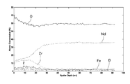
- FIG. 3 shows the results of depth direction analysis by Auger spectroscopy for the magnet after heat treatment (the apparatus uses PHI / 680 manufactured by ULVAC-PHI. For this analysis, the magnet is 13 mm ⁇ A 7 mm surface with one side dialed was used). As is apparent from FIG.
- the thickness of the layer formed on the magnet surface is at least 150 nm
- the Nd content is 35 atomic% to 38 atomic%
- the oxygen content is as large as 55 atomic% to 60 atomic%. It was found that the layer was composed of a compound containing these elements (for example, Nd oxide).
- FIG. 4 shows the result of depth direction analysis by Auger spectroscopy for a magnet having a chemical conversion film on the surface. As is clear from FIG. 4, this chemical conversion film is characterized in that the former is more than the latter when the Zr content in the outer surface half region and the magnet half region of the thickness is compared. It was found that a large amount of a compound containing Zr (for example, a Zr oxide) was contained in the region.
- this chemical conversion film had much Nd content, it turned out that many compounds (for example, Nd oxide and Nd fluoride) containing Nd are contained. Constituent element contents of this chemical conversion film were 3 atomic% to 15 atomic% for Zr, 8 atomic% to 35 atomic% for Nd, about 3 atomic% for fluorine, and 55 atomic% to 70 atomic% for oxygen.
- Example 5 Second embodiment The aging treatment was not performed before the surface treatment, but the heat treatment performed after the surface treatment was combined with the purpose of the aging treatment on the surface of the magnet in the same manner as in Example 4. A chemical conversion film having a thickness of about 30 nm was formed, and the same results as in Example 4 were obtained.
- Example 6 Second Mode A radial ring sintered magnet having the same composition as that of the sintered magnet used in Example 4 and having a diameter of 40 mm ⁇ inner diameter: 33 mm ⁇ length: 9 mm was used in the same manner as in Example 5. A chemical conversion film having a thickness of about 30 nm was formed on the surface of the magnet. The magnet having the chemical conversion film on the surface thus obtained was subjected to a pressure cooker test under the conditions of temperature: 120 ° C., relative humidity: 100%, pressure: 2 atm for 48 hours, and then the powder that had been degranulated with the tape was removed. removed, was determined shedding amount by measuring the weight of the test before and after the magnet, Datsutsuburyou was extremely small was 0.5 g / m 2.
- Comparative Example 4 The same magnet as the radial ring sintered magnet used in Example 6 was heat treated in the same manner as in Example 4, and then ultrasonically washed with water for 1 minute, and then 7.5 g of phosphoric acid was added to ion-exchanged water. Dissolve in 1 liter, adjust the pH to 2.9 with sodium hydroxide and soak for 5 minutes at a bath temperature of 60 ° C. Then, by performing a drying treatment at 160 ° C. for 35 minutes, a chemical conversion film having a film thickness of about 30 nm was formed on the surface of the magnet.
- the amount of degranulation was 6.5 g / m 2 .
- the amount was larger than the shed amount.
- Comparative Example 5 The same magnet as the radial ring sintered magnet used in Example 6 was heat-treated in the same manner as in Example 4, and then ultrasonically washed with water for 1 minute, and then 7 g of chromic acid was added to 1 liter of ion-exchanged water.
- a treatment solution prepared by dissolving in a solution it is immersed in a bath temperature of 60 ° C. for 10 minutes to perform a chemical conversion treatment, and after lifting the magnet from the treatment solution, it is washed with water and dried at 160 ° C. for 35 minutes.
- a chemical conversion film having a film thickness of about 30 nm was formed on the surface.
- the degranulation amount was 9.0 g / m 2 . The amount was larger than the shed amount.
- Example 7 Second embodiment Example 4 using a polar anisotropic ring sintered magnet having the same composition as that of the sintered magnet used in Example 4 but having an outer diameter of 10 mm, an inner diameter of 5.5 mm, and a length of 16 mm.
- a chemical conversion film having a thickness of about 30 nm was formed on the surface of the magnet.
- a pressure cooker test was performed on the magnet having the chemical conversion coating on the surface thus obtained in the same manner as in Example 6 to determine the amount of degranulation. As a result, the amount of degranulation was 1.4 g / m 2 , which was slight.
- Example 8 Second embodiment Power magnets (product name: Nippon Paint Co., Ltd.) were electrodeposited on the magnet having a chemical conversion coating on the surface obtained in Example 6 (epoxy resin cationic electrodeposition coating, conditions: 200 V). 150 seconds) baked and dried at 195 ° C. for 60 minutes to form an epoxy resin film having a thickness of 20 ⁇ m on the surface of the chemical conversion film. A pressure cooker test was conducted in the same manner as in Example 6 on the magnet having the chemical conversion film and the resin film on the surface thus obtained, but no abnormality in the appearance was observed.
- Comparative Example 6 For the magnet having the chemical conversion film on the surface obtained in Comparative Example 4, a resin film having a film thickness of 20 ⁇ m was formed on the surface of the chemical conversion film in the same manner as in Example 8, and the pressure cooker test was performed in the same manner as in Example 6. As a result, swelling was observed on the surface of the resin coating.
- Example 9 Second embodiment For example, as described in US Pat. No. 4,770,723, a known cast ingot is roughly pulverized, and after fine pulverization, molding, sintering, aging treatment, and surface treatment are performed.
- the obtained radial ring sintered magnet of 11Nd-1Dy-3Pr-78Fe-1Co-6B composition (atomic%) having an outer diameter: 35 mm ⁇ inner diameter: 29.5 mm ⁇ length: 50 mm is longitudinal: 30 cm ⁇ horizontal: 20 cm x height: 10 cm size molybdenum box (contained from a container main body and a lid having an opening in the upper part, which can be vented to the outside between the container main body and the lid). Heat treatment was performed in the same manner as in Example 4.
- the appearance of the surface of the magnet after the heat treatment was uniform and had a blackish finish.
- the surface of the magnet was observed by SEM, it was covered with a uniform layer and homogenized.
- the oxygen content of the layer formed on the magnet surface was measured in the same manner as in Example 4, it was about 27 atomic%.
- a chemical conversion film having a thickness of about 30 nm was formed on the surface of the magnet in the same manner as in Example 4.
- a magnet having a chemical conversion coating on the surface thus obtained was immersed in ethanol and subjected to ultrasonic cleaning for 3 minutes, and then a silicone adhesive (SE1750: manufactured by Toray Dow Corning) on the entire inner peripheral surface.
- the same silicone is also applied to the entire outer peripheral surface of the rotor core (diameter: 29.4 mm ⁇ length: 50 mm, material: SS400) made of iron core that has been subjected to ultrasonic cleaning for 3 minutes after being coated with acetone.
- the adhesive is applied, the rotor core is inserted into the inner diameter of the magnet, heat-treated in the atmosphere at 150 ° C. for 1.5 hours, and left at room temperature for 60 hours, so that the thickness of the adhesive layer is 50 ⁇ m.
- An adhesive body composed of a magnet and a rotor core was obtained.
- the shear strength of the body was compared (the shear test was carried out using UTM-1-5000C manufactured by Toyo Baldwin). As a result, the shear strength before leaving in a high-temperature and high-humidity environment was 4.8 MPa, whereas the shear strength after leaving for 250 hours and the shear strength after leaving for 500 hours were both 4.05 MPa. It was found that the shear strength was still higher than the shear strength before leaving the environment. The separation between the magnet and the rotor core was due to cohesive failure of the adhesive in any case.
- the present invention is industrially advantageous in that it can provide an R—Fe—B based sintered magnet having a chemical conversion film on the surface, which has better corrosion resistance than a conventional chemical conversion film such as a phosphate film, and a method for producing the same. Has availability.
Landscapes
- Engineering & Computer Science (AREA)
- Chemical & Material Sciences (AREA)
- Power Engineering (AREA)
- Mechanical Engineering (AREA)
- Organic Chemistry (AREA)
- Materials Engineering (AREA)
- Metallurgy (AREA)
- Manufacturing & Machinery (AREA)
- Environmental & Geological Engineering (AREA)
- Chemical Kinetics & Catalysis (AREA)
- Crystallography & Structural Chemistry (AREA)
- Inorganic Chemistry (AREA)
- General Chemical & Material Sciences (AREA)
- Physics & Mathematics (AREA)
- Electromagnetism (AREA)
- Hard Magnetic Materials (AREA)
- Manufacturing Cores, Coils, And Magnets (AREA)
- Powder Metallurgy (AREA)
- Chemical Treatment Of Metals (AREA)
Abstract
Priority Applications (5)
| Application Number | Priority Date | Filing Date | Title |
|---|---|---|---|
| JP2010506724A JP4586937B2 (ja) | 2008-07-04 | 2009-06-30 | 耐食性磁石およびその製造方法 |
| US13/002,571 US8641833B2 (en) | 2008-07-04 | 2009-06-30 | Corrosion-resistant magnet and method for producing the same |
| CN2009801255950A CN102084438B (zh) | 2008-07-04 | 2009-06-30 | 耐腐蚀性磁铁及其制造方法 |
| EP09773456.0A EP2299455B1 (fr) | 2008-07-04 | 2009-06-30 | Aimant résistant à la corrosion et son procédé de production |
| US14/089,543 US9275795B2 (en) | 2008-07-04 | 2013-11-25 | Corrosion-resistant magnet and method for producing the same |
Applications Claiming Priority (4)
| Application Number | Priority Date | Filing Date | Title |
|---|---|---|---|
| JP2008176029 | 2008-07-04 | ||
| JP2008176033 | 2008-07-04 | ||
| JP2008-176033 | 2008-07-04 | ||
| JP2008-176029 | 2008-07-04 |
Related Child Applications (2)
| Application Number | Title | Priority Date | Filing Date |
|---|---|---|---|
| US13/002,571 A-371-Of-International US8641833B2 (en) | 2008-07-04 | 2009-06-30 | Corrosion-resistant magnet and method for producing the same |
| US14/089,543 Division US9275795B2 (en) | 2008-07-04 | 2013-11-25 | Corrosion-resistant magnet and method for producing the same |
Publications (2)
| Publication Number | Publication Date |
|---|---|
| WO2010001878A2 true WO2010001878A2 (fr) | 2010-01-07 |
| WO2010001878A3 WO2010001878A3 (fr) | 2010-02-25 |
Family
ID=41466398
Family Applications (1)
| Application Number | Title | Priority Date | Filing Date |
|---|---|---|---|
| PCT/JP2009/061913 WO2010001878A2 (fr) | 2008-07-04 | 2009-06-30 | Aimant résistant à la corrosion et son procédé de production |
Country Status (5)
| Country | Link |
|---|---|
| US (2) | US8641833B2 (fr) |
| EP (1) | EP2299455B1 (fr) |
| JP (2) | JP4586937B2 (fr) |
| CN (1) | CN102084438B (fr) |
| WO (1) | WO2010001878A2 (fr) |
Cited By (2)
| Publication number | Priority date | Publication date | Assignee | Title |
|---|---|---|---|---|
| WO2011081170A1 (fr) * | 2009-12-28 | 2011-07-07 | 日立金属株式会社 | Aimant résistant à la corrosion et son procédé de fabrication |
| US11365464B2 (en) | 2018-08-31 | 2022-06-21 | Lg Chem, Ltd. | Method for preparing magnetic powder and magnetic material |
Families Citing this family (1)
| Publication number | Priority date | Publication date | Assignee | Title |
|---|---|---|---|---|
| JP5573663B2 (ja) * | 2010-12-27 | 2014-08-20 | 日立金属株式会社 | 耐食性磁石の製造方法 |
Citations (1)
| Publication number | Priority date | Publication date | Assignee | Title |
|---|---|---|---|---|
| US4770723A (en) | 1982-08-21 | 1988-09-13 | Sumitomo Special Metals Co., Ltd. | Magnetic materials and permanent magnets |
Family Cites Families (15)
| Publication number | Priority date | Publication date | Assignee | Title |
|---|---|---|---|---|
| JPH0442517A (ja) | 1990-06-08 | 1992-02-13 | Shin Etsu Chem Co Ltd | 耐食性希土類永久磁石の製造方法 |
| JP2001076914A (ja) * | 1998-12-17 | 2001-03-23 | Sumitomo Special Metals Co Ltd | 希土類系永久磁石およびその製造方法 |
| JP2000199074A (ja) | 1998-12-28 | 2000-07-18 | Nippon Parkerizing Co Ltd | 希土類・鉄系焼結永久磁石の沈着型表面処理液および表面処理方法、ならびに該表面処理方法により得られた表面を有する希土類・鉄系焼結永久磁石 |
| US6281774B1 (en) * | 1999-09-10 | 2001-08-28 | Sumitomo Special Metals Co., Ltd. | Corrosion-resistant permanent magnet and method for producing the same |
| DE60106695T2 (de) * | 2000-08-11 | 2005-03-31 | Neomax Co., Ltd. | Auf einem Seltenerdmetall basierender Permanentmagnet mit einem korrosionsbeständigen Film und Verfahren zu seiner Herstellung |
| JP2002198241A (ja) | 2000-08-11 | 2002-07-12 | Sumitomo Special Metals Co Ltd | 耐食性被膜を有する希土類系永久磁石およびその製造方法 |
| TWI268965B (en) * | 2001-06-15 | 2006-12-21 | Nihon Parkerizing | Treating solution for surface treatment of metal and surface treatment method |
| JP4225063B2 (ja) * | 2003-01-10 | 2009-02-18 | 日立金属株式会社 | 高耐食性永久磁石およびその製造方法 |
| CN1934660A (zh) * | 2004-06-30 | 2007-03-21 | 信越化学工业株式会社 | 耐腐蚀的稀土磁体及其制造方法 |
| JP2006161110A (ja) * | 2004-12-08 | 2006-06-22 | Nippon Paint Co Ltd | 車両のシャシ用金属表面の塗装前処理方法及び粉体塗料の塗装方法 |
| JP2007116088A (ja) * | 2005-09-26 | 2007-05-10 | Hitachi Ltd | 磁性材料,磁石及び回転機 |
| JP4797906B2 (ja) * | 2005-09-26 | 2011-10-19 | 株式会社日立製作所 | 磁性材料,磁石及び回転機 |
| JP4415980B2 (ja) * | 2006-08-30 | 2010-02-17 | 株式会社日立製作所 | 高抵抗磁石およびそれを用いたモータ |
| JP4564993B2 (ja) * | 2007-03-29 | 2010-10-20 | 株式会社日立製作所 | 希土類磁石及びその製造方法 |
| JP4900121B2 (ja) * | 2007-03-29 | 2012-03-21 | 日立化成工業株式会社 | フッ化物コート膜形成処理液およびフッ化物コート膜形成方法 |
-
2009
- 2009-06-30 CN CN2009801255950A patent/CN102084438B/zh active Active
- 2009-06-30 JP JP2010506724A patent/JP4586937B2/ja active Active
- 2009-06-30 US US13/002,571 patent/US8641833B2/en active Active
- 2009-06-30 WO PCT/JP2009/061913 patent/WO2010001878A2/fr active Application Filing
- 2009-06-30 EP EP09773456.0A patent/EP2299455B1/fr active Active
-
2010
- 2010-06-04 JP JP2010128628A patent/JP5516092B2/ja active Active
-
2013
- 2013-11-25 US US14/089,543 patent/US9275795B2/en active Active
Patent Citations (1)
| Publication number | Priority date | Publication date | Assignee | Title |
|---|---|---|---|---|
| US4770723A (en) | 1982-08-21 | 1988-09-13 | Sumitomo Special Metals Co., Ltd. | Magnetic materials and permanent magnets |
Non-Patent Citations (1)
| Title |
|---|
| See also references of EP2299455A4 |
Cited By (3)
| Publication number | Priority date | Publication date | Assignee | Title |
|---|---|---|---|---|
| WO2011081170A1 (fr) * | 2009-12-28 | 2011-07-07 | 日立金属株式会社 | Aimant résistant à la corrosion et son procédé de fabrication |
| JP5573848B2 (ja) * | 2009-12-28 | 2014-08-20 | 日立金属株式会社 | 耐食性磁石およびその製造方法 |
| US11365464B2 (en) | 2018-08-31 | 2022-06-21 | Lg Chem, Ltd. | Method for preparing magnetic powder and magnetic material |
Also Published As
| Publication number | Publication date |
|---|---|
| CN102084438A (zh) | 2011-06-01 |
| EP2299455B1 (fr) | 2018-09-19 |
| WO2010001878A3 (fr) | 2010-02-25 |
| JPWO2010001878A1 (ja) | 2011-12-22 |
| US9275795B2 (en) | 2016-03-01 |
| US8641833B2 (en) | 2014-02-04 |
| CN102084438B (zh) | 2012-11-21 |
| JP5516092B2 (ja) | 2014-06-11 |
| JP2010263223A (ja) | 2010-11-18 |
| EP2299455A4 (fr) | 2017-05-17 |
| JP4586937B2 (ja) | 2010-11-24 |
| US20140083568A1 (en) | 2014-03-27 |
| EP2299455A2 (fr) | 2011-03-23 |
| US20110186181A1 (en) | 2011-08-04 |
Similar Documents
| Publication | Publication Date | Title |
|---|---|---|
| JP5573848B2 (ja) | 耐食性磁石およびその製造方法 | |
| JP4591631B2 (ja) | 耐食性磁石およびその製造方法 | |
| JP2008263208A (ja) | 耐食性希土類磁石 | |
| EP1734539B1 (fr) | Aimants de terre rare résistants à la corrosion et leur procédé de production | |
| US6281774B1 (en) | Corrosion-resistant permanent magnet and method for producing the same | |
| JP5516092B2 (ja) | 耐食性磁石およびその製造方法 | |
| JPS63217601A (ja) | 耐食性永久磁石及びその製造方法 | |
| JP3176597B2 (ja) | 耐食性永久磁石およびその製造方法 | |
| JP5573663B2 (ja) | 耐食性磁石の製造方法 | |
| JP3993613B2 (ja) | 磁石及びその製造方法 | |
| JP3248982B2 (ja) | 永久磁石およびその製造方法 | |
| JP2006049864A (ja) | 耐食性希土類磁石及びその製造方法 | |
| JPH04288804A (ja) | 永久磁石およびその製造方法 | |
| JP2631493B2 (ja) | 耐食性永久磁石の製造方法 | |
| JP3734479B2 (ja) | 希土類磁石の製造方法 | |
| JP2004273582A (ja) | 接着性に優れた希土類永久磁石 | |
| JPH0529120A (ja) | 高耐食性希土類磁石およびその製造法 | |
| JPH0491406A (ja) | 樹脂成形型磁石 | |
| JPH05109519A (ja) | 高耐食性希土類磁石およびその製法 | |
| JPS63166975A (ja) | 耐酸化性のすぐれた永久磁石の製造方法 | |
| JPH1064745A (ja) | 高耐食性永久磁石の製造方法 | |
| JP2003224024A (ja) | 耐食性永久磁石の製造方法 | |
| JPH0680609B2 (ja) | 耐酸化性のすぐれた永久磁石の製造方法 | |
| JP2007258698A (ja) | 希土類磁石の製造方法 |
Legal Events
| Date | Code | Title | Description |
|---|---|---|---|
| WWE | Wipo information: entry into national phase |
Ref document number: 200980125595.0 Country of ref document: CN |
|
| WWE | Wipo information: entry into national phase |
Ref document number: 2010506724 Country of ref document: JP |
|
| 121 | Ep: the epo has been informed by wipo that ep was designated in this application |
Ref document number: 09773456 Country of ref document: EP Kind code of ref document: A2 |
|
| WWE | Wipo information: entry into national phase |
Ref document number: 2009773456 Country of ref document: EP |
|
| NENP | Non-entry into the national phase in: |
Ref country code: DE |
|
| WWE | Wipo information: entry into national phase |
Ref document number: 13002571 Country of ref document: US |