WO2009157192A1 - 非水電解質二次電池用電極構造体、その製造方法、および非水電解質二次電池 - Google Patents
非水電解質二次電池用電極構造体、その製造方法、および非水電解質二次電池 Download PDFInfo
- Publication number
- WO2009157192A1 WO2009157192A1 PCT/JP2009/002889 JP2009002889W WO2009157192A1 WO 2009157192 A1 WO2009157192 A1 WO 2009157192A1 JP 2009002889 W JP2009002889 W JP 2009002889W WO 2009157192 A1 WO2009157192 A1 WO 2009157192A1
- Authority
- WO
- WIPO (PCT)
- Prior art keywords
- electrode
- electrolyte secondary
- electrode lead
- secondary battery
- lead
- Prior art date
Links
Images


Classifications
-
- H—ELECTRICITY
- H01—ELECTRIC ELEMENTS
- H01M—PROCESSES OR MEANS, e.g. BATTERIES, FOR THE DIRECT CONVERSION OF CHEMICAL ENERGY INTO ELECTRICAL ENERGY
- H01M4/00—Electrodes
- H01M4/02—Electrodes composed of, or comprising, active material
- H01M4/64—Carriers or collectors
- H01M4/70—Carriers or collectors characterised by shape or form
-
- H—ELECTRICITY
- H01—ELECTRIC ELEMENTS
- H01M—PROCESSES OR MEANS, e.g. BATTERIES, FOR THE DIRECT CONVERSION OF CHEMICAL ENERGY INTO ELECTRICAL ENERGY
- H01M10/00—Secondary cells; Manufacture thereof
- H01M10/05—Accumulators with non-aqueous electrolyte
- H01M10/052—Li-accumulators
-
- H—ELECTRICITY
- H01—ELECTRIC ELEMENTS
- H01M—PROCESSES OR MEANS, e.g. BATTERIES, FOR THE DIRECT CONVERSION OF CHEMICAL ENERGY INTO ELECTRICAL ENERGY
- H01M4/00—Electrodes
- H01M4/02—Electrodes composed of, or comprising, active material
- H01M4/64—Carriers or collectors
- H01M4/70—Carriers or collectors characterised by shape or form
- H01M4/72—Grids
- H01M4/74—Meshes or woven material; Expanded metal
- H01M4/742—Meshes or woven material; Expanded metal perforated material
-
- H—ELECTRICITY
- H01—ELECTRIC ELEMENTS
- H01M—PROCESSES OR MEANS, e.g. BATTERIES, FOR THE DIRECT CONVERSION OF CHEMICAL ENERGY INTO ELECTRICAL ENERGY
- H01M50/00—Constructional details or processes of manufacture of the non-active parts of electrochemical cells other than fuel cells, e.g. hybrid cells
- H01M50/50—Current conducting connections for cells or batteries
- H01M50/531—Electrode connections inside a battery casing
- H01M50/533—Electrode connections inside a battery casing characterised by the shape of the leads or tabs
-
- H—ELECTRICITY
- H01—ELECTRIC ELEMENTS
- H01M—PROCESSES OR MEANS, e.g. BATTERIES, FOR THE DIRECT CONVERSION OF CHEMICAL ENERGY INTO ELECTRICAL ENERGY
- H01M10/00—Secondary cells; Manufacture thereof
- H01M10/05—Accumulators with non-aqueous electrolyte
- H01M10/058—Construction or manufacture
-
- H—ELECTRICITY
- H01—ELECTRIC ELEMENTS
- H01M—PROCESSES OR MEANS, e.g. BATTERIES, FOR THE DIRECT CONVERSION OF CHEMICAL ENERGY INTO ELECTRICAL ENERGY
- H01M50/00—Constructional details or processes of manufacture of the non-active parts of electrochemical cells other than fuel cells, e.g. hybrid cells
- H01M50/50—Current conducting connections for cells or batteries
- H01M50/531—Electrode connections inside a battery casing
- H01M50/534—Electrode connections inside a battery casing characterised by the material of the leads or tabs
-
- Y—GENERAL TAGGING OF NEW TECHNOLOGICAL DEVELOPMENTS; GENERAL TAGGING OF CROSS-SECTIONAL TECHNOLOGIES SPANNING OVER SEVERAL SECTIONS OF THE IPC; TECHNICAL SUBJECTS COVERED BY FORMER USPC CROSS-REFERENCE ART COLLECTIONS [XRACs] AND DIGESTS
- Y02—TECHNOLOGIES OR APPLICATIONS FOR MITIGATION OR ADAPTATION AGAINST CLIMATE CHANGE
- Y02E—REDUCTION OF GREENHOUSE GAS [GHG] EMISSIONS, RELATED TO ENERGY GENERATION, TRANSMISSION OR DISTRIBUTION
- Y02E60/00—Enabling technologies; Technologies with a potential or indirect contribution to GHG emissions mitigation
- Y02E60/10—Energy storage using batteries
-
- Y—GENERAL TAGGING OF NEW TECHNOLOGICAL DEVELOPMENTS; GENERAL TAGGING OF CROSS-SECTIONAL TECHNOLOGIES SPANNING OVER SEVERAL SECTIONS OF THE IPC; TECHNICAL SUBJECTS COVERED BY FORMER USPC CROSS-REFERENCE ART COLLECTIONS [XRACs] AND DIGESTS
- Y02—TECHNOLOGIES OR APPLICATIONS FOR MITIGATION OR ADAPTATION AGAINST CLIMATE CHANGE
- Y02P—CLIMATE CHANGE MITIGATION TECHNOLOGIES IN THE PRODUCTION OR PROCESSING OF GOODS
- Y02P70/00—Climate change mitigation technologies in the production process for final industrial or consumer products
- Y02P70/50—Manufacturing or production processes characterised by the final manufactured product
-
- Y—GENERAL TAGGING OF NEW TECHNOLOGICAL DEVELOPMENTS; GENERAL TAGGING OF CROSS-SECTIONAL TECHNOLOGIES SPANNING OVER SEVERAL SECTIONS OF THE IPC; TECHNICAL SUBJECTS COVERED BY FORMER USPC CROSS-REFERENCE ART COLLECTIONS [XRACs] AND DIGESTS
- Y10—TECHNICAL SUBJECTS COVERED BY FORMER USPC
- Y10T—TECHNICAL SUBJECTS COVERED BY FORMER US CLASSIFICATION
- Y10T29/00—Metal working
- Y10T29/49—Method of mechanical manufacture
- Y10T29/49002—Electrical device making
- Y10T29/49108—Electric battery cell making
Definitions
- the present invention relates to an electrode structure used for a non-aqueous electrolyte secondary battery such as a lithium ion secondary battery, and a non-aqueous electrolyte secondary battery, and more particularly to improvement of a joint portion between an electrode and an electrode lead.
- non-aqueous electrolyte secondary batteries represented by lithium ion secondary batteries have a high energy density and are easily developed because they are easy to reduce in weight.
- non-aqueous electrolyte secondary batteries are required to have higher capacities.
- an active material layer is formed on the surface of a current collector made of a long strip of metal foil by applying a paint containing an active material, a binder, a conductive material, etc. It is common to constitute (a positive electrode and a negative electrode).
- the current collector is connected to external terminals such as a battery case and a sealing plate by electrode leads made of strip-shaped metal pieces.
- the current collector is connected to the electrode lead at the exposed portion of the current collector where the current collector is exposed on the surface of the electrode because sufficient conduction cannot be obtained from above the active material layer.
- the exposed portion of the current collector is formed by removing a part of the active material layer of the current collector over the entire width, or by preventing a part of the current collector from being coated over the entire width (patent) Reference 1 and 2).
- the electrode lead is overlapped on the exposed portion of the current collector, and burring processing or the like is performed so as to penetrate the electrode lead and the current collector from the electrode lead side in the overlapping portion, and a part of the electrode lead is It has been proposed to connect the current collector and the electrode lead by, for example, caulking after passing through (see Patent Documents 3 and 4).
- the exposed portion of the current collector is formed to connect the electrode lead as in the above prior art
- the exposed portion having a width wider than the width of the electrode lead is formed so as to allow a certain margin.
- the active material layer is not formed by a conventional coating method, but an active material containing silicon (Si), germanium (Ge) or tin (Sn) is used.
- a method of forming an active material layer by vapor deposition on a current collector has attracted attention, and a method for its practical use has been sought.
- the binder contained in the active material layer can be reduced or eliminated.
- voids in the active material layer can be reduced or eliminated.
- the active material layer is integrally formed with the current collector, the conductivity between the active material layer and the current collector is extremely good, and the conductive material included in the active material layer is reduced or eliminated. can do. For this reason, it is possible to increase the capacity while reducing the thickness of the electrode. Therefore, it is expected as a technology capable of realizing high performance in terms of capacity and cycle life.
- the active material layer is formed on the current collector by vapor deposition, it is difficult to form the exposed portion on the current collector.
- the coating method for example, when a paint containing an active material is applied using a die coater while feeding a long strip-shaped current collector in the longitudinal direction, the current collector is exposed by applying the paint intermittently. The part can be formed. In addition, it is relatively easy to partially remove the formed active material layer to form the exposed portion of the current collector.
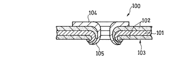
- the caulking portion 105 of the electrode lead 104 as shown in Patent Documents 3 and 4 is not the exposed portion of the current collector 101 but the active material layer 102 is present. It is also conceivable to form it on the part to be.
- the active material layer 102 is sandwiched between the caulking portion 105 and the current collector 101. For this reason, there is an inconvenience that conduction between the current collector 101 and the electrode lead 104 becomes unstable or electrical resistance between the electrode lead and the current collector becomes high. In particular, when an insulating layer is formed on the active material layer in order to increase the safety and reliability of the battery, the electrical resistance between the electrode lead and the current collector is increased.
- the present invention has been made in view of the above problems, and without reducing the amount of active material to be carried on the current collector, stably joining the current collector and the electrode lead so as to conduct, It aims at providing the electrode structure for nonaqueous electrolyte secondary batteries which can achieve high capacity
- the present invention provides a current collector made of a long strip-shaped metal foil, and an electrode including an active material layer formed on both main surfaces of the current collector, An electrode lead; A current collector exposed in at least one of an end of the electrode, a through-hole penetrating the electrode, and a recess provided so as to remove the active material layer from any main surface of the electrode A bonding portion for bonding the electrode and the electrode lead so that the body and the electrode lead are electrically connected; An electrode structure for a non-aqueous electrolyte secondary battery is provided.
- the joint is formed at one end in the width direction of the electrode.
- the electrode lead is An overlapping portion that overlaps with the electrode, and an end surface that is arranged to be flush with an end surface of one end portion in the width direction of the electrode,
- the joining portion is provided so as to span between an end surface of one end portion in the width direction of the electrode and one end surface of the electrode lead.
- the joint is also formed at the other end in the width direction of the electrode.
- the electrode lead has a step portion formed flush with an end surface of the other end portion in the width direction of the electrode. And A joint formed at the other end joins the current collector exposed at the other end in the width direction of the electrode and the step portion of the electrode lead.
- the electrode lead and the other end in the width direction of the electrode are fixed by an adhesive tape.
- the joint is in contact with a first contact portion that contacts one end surface of the electrode lead, and an end surface of one end portion of the electrode.
- a second contact portion, and a folded portion between the first contact portion and the second contact portion, One end surface of the electrode lead and an end surface of one end portion of the electrode are arranged to face each other.
- the joint is formed at one end in the longitudinal direction of the electrode.
- the electrode lead is An overlapping portion that overlaps the electrode, and an end surface that is arranged to be flush with an end surface of one end portion in the longitudinal direction of the electrode,
- the joint portion is provided so as to be spanned between an end surface of one end portion in the longitudinal direction of the electrode and one end surface of the electrode lead.
- the other end of the electrode lead is fixed to the electrode with an adhesive tape.
- the electrode lead has a cut-and-raised part cut and raised part thereof,
- the said junction part is comprised from the re-solidification body of the said cut-and-raised part inserted in the said through-hole.
- the cut-out portion of the electrode lead has a sharp tip.
- the cut-out portion of the electrode lead has a square shape.
- the cut-out portion of the electrode lead has a rounded tip.
- the electrode has the slit-shaped through hole or recess formed at a position overlapping or adjacent to the end of the electrode lead.
- the joint is composed of a re-solidified body at the end of the electrode lead, and joins the current collector exposed inside the slit-shaped through hole or recess to the electrode lead. .
- the slit-shaped through hole or recess is provided in parallel with the longitudinal direction of the electrode.
- the slit-shaped through hole or recess is provided perpendicular to the longitudinal direction of the electrode.
- the slit-like through hole or recess is provided obliquely with respect to the longitudinal direction of the electrode.
- a caulking / crimping portion is provided by penetrating a part of the electrode lead in the thickness direction of the electrode.
- the electrode lead and the electrode are bonded with an adhesive at an overlapping portion.
- the present invention also includes (a) a step of preparing an electrode in which an active material layer is formed on both main surfaces of a current collector made of a long strip-shaped metal foil, and (b) an end portion of the electrode and the electrode.
- the exposed current collector is electrically connected to the electrode lead.
- the step b includes the electrode lead and the electrode so that at least a part thereof overlaps with each other and the electrode lead.
- the one end face of the electrode and the one end face in the width direction of the electrode are arranged so as to be flush with each other, and the one end face of the electrode lead and the one end face in the width direction of the electrode Forming a joint.
- the step b further opposes one end surface of the electrode lead and one end surface of the electrode in the width direction. A step of folding back the joint portion.
- the step b inserts a cut-and-raised portion obtained by cutting and raising a part of the electrode lead into the through hole. And a step of melting and re-solidifying the cut and raised portion to form the joint portion.
- the step b comprises Forming the slit-shaped through-hole or recess at a position overlapping or adjacent to the end of the electrode lead of the electrode; and melting the end of the electrode lead, And a step of forming the joint by re-solidification after pouring into the through hole or the recess.
- the present invention provides an electrode group configured by winding or laminating a long belt-like positive electrode and a negative electrode with a separator interposed therebetween, An electrode lead joined to each of the positive electrode and the negative electrode;
- Non-aqueous electrolyte A battery case that houses the electrode group and the non-aqueous electrolyte, and a sealing body that seals an opening of the battery case,
- a non-aqueous electrolyte secondary battery in which at least one of the electrode structures constituted by joining electrode leads to the positive electrode and the negative electrode is composed of the electrode structure for non-aqueous electrolyte secondary batteries described above.
- the electrode does not form a large active material layer non-formation portion and reduces the electric resistance between the electrode and the electrode lead. And the electrode lead can be joined. Thereby, it becomes easier to increase the amount of the active material that can be included in the battery than before, and the capacity can be increased. Therefore, it becomes easy to increase the capacity of the nonaqueous electrolyte secondary battery.
- FIG. 1 It is a perspective view which shows schematic structure of the electrode structure for nonaqueous electrolyte secondary batteries which concerns on Embodiment 1 of this invention. It is sectional drawing of the electrode structure for nonaqueous electrolyte secondary batteries same as the above. It is a perspective view which shows the modification of the electrode structure for nonaqueous electrolyte secondary batteries same as the above. It is a perspective view which shows another modification of the electrode structure for nonaqueous electrolyte secondary batteries same as the above. It is a perspective view which shows another modification of the electrode structure for nonaqueous electrolyte secondary batteries same as the above. It is a perspective view which shows another modification of the electrode structure for nonaqueous electrolyte secondary batteries same as the above. It is a perspective view which shows another modification of the electrode structure for nonaqueous electrolyte secondary batteries same as the above.
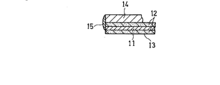
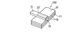
- Electrode structure 10 in the illustrated example is used for a non-aqueous electrolyte secondary battery represented by a lithium ion secondary battery, and is formed on both main surfaces of a current collector 11 made of a long strip-shaped metal foil. And an electrode lead 14 for connecting the electrode 13 to external terminals (battery case, sealing plate, etc.) of the nonaqueous electrolyte secondary battery. Yes.
- the electrode structure 10 further includes a predetermined number (two in the illustrated example) of joints 15 that join the electrode 13 and the electrode lead 14 while the current collector 11 and the electrode lead 14 are electrically connected. Yes.
- the electrode lead 14 has a strip-like flat shape, and a part thereof is arranged so as to overlap the electrode 13 from above the active material layer 12. In addition, the electrode lead 14 is disposed so that one end surface thereof is flush with the end surface of one end portion in the width direction of the electrode 13.
- the junction 15 is formed so as to connect the current collector 11 exposed at the end face of one end in the width direction of the electrode 13 and the electrode lead 14.
- the formation of the joint portion 15 is performed by plasma welding using, for example, a filler material.
- the current collector 11 exposed at the end face of the one end portion in the width direction of the electrode 13 and the electrode lead 14 are electrically connected by the joint portion 15.
- the electrode 13 and the electrode lead 14 are joined. This eliminates the need to form the exposed portion of the current collector 11 for connecting the electrode lead 14 to the current collector 11 on the main surface of the electrode 13, so that the active surface is entirely formed on both main surfaces of the current collector 11. It becomes possible to carry a substance. As a result, it is possible to increase the amount of the active material supported on the current collector 11 as compared with the conventional case. Moreover, since the area of the active material layer 12 can be increased, the reaction area between the positive electrode and the negative electrode is also increased. Therefore, by applying the electrode structure 10 to a non-aqueous electrolyte secondary battery, a high-capacity non-aqueous electrolyte secondary battery can be configured.
- the joint portion 15 is provided so as to contact only the end surface of one end portion in the width direction of the electrode 13 and one end surface of the electrode lead.
- the current collector 11 and the electrode lead 14 are electrically connected without causing any damage to the active material layer 12 provided on the main surface of the electrode 13.
- the joint portion 15 is provided at one end portion in the width direction of the electrode 13, the attachment position in the longitudinal direction of the electrode 13 of the electrode lead 14 can be freely selected. Therefore, by using this electrode structure 10 for a non-aqueous electrolyte secondary battery, it is possible to configure a non-aqueous electrolyte secondary battery with a high degree of design freedom.
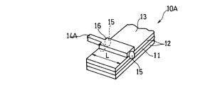
- FIG. 2 shows a modification of the electrode structure for a nonaqueous electrolyte secondary battery in FIG. 1A.
- the joint 15 is formed not only at one end in the width direction of the electrode 13 but also at the other end.
- the electrode lead 14 ⁇ / b> A in the illustrated example has step portions 16 formed on both sides of the position of the length L from one end surface thereof.
- the length L is the width of the electrode 13.
- the joint portion 15 is formed so as to span between the step portion 16 on both sides of the electrode lead 14 and the end surface of the other end portion in the width direction of the electrode 13.
- this modification by forming the joint portions 15 at both one end and the other end in the width direction of the electrode 13, it is possible to further increase the joint strength between the electrode 13 and the electrode lead 14A.
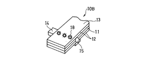
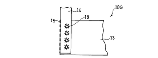
- FIG. 3 shows another modification of the electrode structure.
- a predetermined number three in the illustrated example
- caulking portions 18 for fixing the electrode lead 14 to the electrode 13 are provided in a portion where the electrode 13 and the electrode lead 14 overlap. It has been.
- the caulking portion 18 is formed by raising a part of the electrode lead 14 so as to penetrate the electrode 13 and bending the part penetrating the electrode 13 by burring or the like.
- the electrode lead 14 is joined to the electrode 13 by the joining portion 15, and the electrode 13 and the electrode lead are provided by providing the caulking portion 18 of the electrode lead 14 at the portion where the electrode 13 and the electrode lead 14 overlap. It is possible to further increase the bonding strength with.
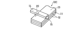
- FIG. 4 shows still another modification of the electrode structure.
- the electrode lead 14 is fixed to the electrode 13 with the adhesive tape 20 at the other end portion in the width direction of the electrode 13.
- the adhesive tape 20 is attached so as to span between the surface of the electrode lead 14 on the side in contact with the electrode 13 and the end surface of the other end portion in the width direction of the electrode 13. Is preferred.
- the electrode lead 14 is joined to the electrode 13 by the joining portion 15, while the electrode lead 14 is fixed to the electrode 13 by the adhesive tape 20 at the other end in the width direction of the electrode 13. It is possible to further increase the bonding strength with the electrode lead 14. In addition, when the caulking portion 18 is provided, the surface of the electrode lead 14 is thereby uneven. In contrast, by fixing the electrode lead 14 to the electrode 13 with the adhesive tape 20 in the manner shown in FIG. 4, the bonding strength between the electrode 13 and the electrode lead 14 without causing irregularities on the surface of the electrode lead 14. Can be made larger. Accordingly, it is possible to prevent inconveniences such as the surface of the electrode 13 being damaged when the electrode group is formed by winding the electrode 13 or the like.
- the active material layer 12 of the electrode 13 is inevitably damaged.
- the adhesive tape 20 when the adhesive tape 20 is used, the bonding strength between the electrode 13 and the electrode lead 14 can be further increased without damaging the active material layer 12. Thereby, the capacity can be further increased.
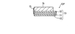
- FIG. 5 shows still another modification of the electrode structure.
- the portion of the electrode lead 14 that overlaps the electrode 13 is bonded to the electrode 13 with the adhesive 22.
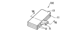
- FIG. 6 shows still another modification of the electrode structure.
- the electrode structure 10E of this modification is configured by folding back the electrode lead 14 of the electrode structure 10 of FIG. 1A so that one end face of the electrode lead 14 and one end face in the width direction of the electrode 13 face each other. Has been.
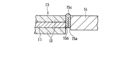
- FIG. 7 shows an enlarged cross section taken along line VII-VII in FIG.
- the joint 15 has a first contact portion 15 a that contacts one end surface of the electrode lead 14 and a width direction of the electrode 13.
- the 2nd contact part 15b which contacts the end surface of one end part, and the folding
- the electrode lead 14 By folding the electrode lead 14 in this way, it is possible to prevent the thickness of the electrode structure from increasing at the overlapping portion of the electrode 13 and the electrode lead 14. Therefore, the shape of the electrode structure can be prevented from being distorted, and the capacity can be further increased.
- the foil made from aluminum or aluminum alloy can be used for a positive electrode electrical power collector.
- the thickness can be 5 ⁇ m to 50 ⁇ m.
- the positive electrode active material layer is formed by applying a positive electrode mixture paint on the surface of the positive electrode current collector, drying, and rolling.
- the positive electrode mixture paint is prepared by mixing and dispersing a positive electrode active material, a conductive material, and a binder in a dispersion medium using a dispersing machine such as a planetary mixer.
- the positive electrode active material examples include lithium cobaltate and modified products thereof (such as lithium cobaltate in which aluminum or magnesium is dissolved), lithium nickelate and modified products thereof (part of nickel substituted with cobalt, etc.) ), And composite oxides such as lithium manganate and modified products thereof.
- the positive electrode conductive material for example, acetylene black, ketjen black, channel black, furnace black, lamp black, thermal black, and other carbon black, and various graphites can be used alone or in combination.
- the positive electrode binder for example, polyvinylidene fluoride (PVdF), a modified polyvinylidene fluoride, polytetrafluoroethylene (PTFE), a rubber particle binder having an acrylate unit, or the like can be used. It is also possible to mix an acrylate monomer or an acrylate oligomer into which a reactive functional group has been introduced into the binder.
- PVdF polyvinylidene fluoride
- PTFE polytetrafluoroethylene
- the negative electrode is not particularly limited, rolled copper foil, electrolytic copper foil, or the like can be used as the negative electrode current collector.
- the thickness of the negative electrode current collector can be 5 ⁇ m to 50 ⁇ m.
- the negative electrode active material layer is formed by applying a negative electrode mixture paint on the surface of the negative electrode current collector, drying, and rolling.
- the negative electrode mixture paint is prepared by mixing and dispersing a negative electrode active material, a binder, and, if necessary, a conductive material and a thickener in a dispersion medium using a dispersing machine such as a planetary mixer.
- a carbon material such as graphite, an alloy-based material, or the like is preferably used.
- the alloy material silicon oxide, silicon, silicon alloy, tin oxide, tin, tin alloy and the like can be used. Of these, silicon oxide is particularly preferable.
- the silicon oxide is represented by the general formula SiO x and desirably has a composition satisfying 0 ⁇ x ⁇ 2, preferably 0.01 ⁇ x ⁇ 1.
- the metal element other than silicon in the silicon alloy is preferably a metal element that does not form an alloy with lithium, such as titanium, copper, or nickel.
- binder for the negative electrode various binders including PVdF and modified products thereof can be used. However, from the viewpoint of improving the lithium ion acceptability, it is preferable to use styrene-butadiene copolymer rubber particles (SBR) and modified products thereof as the binder for the negative electrode.
- SBR styrene-butadiene copolymer rubber particles
- the negative electrode thickener is not particularly limited as long as the aqueous solution is a viscous material such as polyethylene oxide (PEO) and polyvinyl alcohol (PVA).
- cellulose resins such as carboxymethyl cellulose (CMC) and modified products thereof are preferred from the viewpoint of dispersibility and thickening of the mixture paint.
- the active material layer 12 may be formed by forming a thin film of the active material on the surface of the current collector 11.
- a dry process such as a vapor deposition method, a sputtering method, and a CVD method, which are vacuum processes, can be used.
- the thickness of the active material thin film formed by these methods varies depending on the required characteristics of the non-aqueous secondary battery to be produced, but is preferably in the range of 5 to 30 ⁇ m, more preferably in the range of 10 to 25 ⁇ m. More preferred.
- Example 1 An electrode structure having the same structure as that shown in FIG. 1A was produced as follows. A copper foil having a thickness of 26 ⁇ m was used as the current collector 11. An active material layer 12 having a thickness of 20 ⁇ m made of an oxide of Si (silicon) was formed on both surfaces of the current collector 11 by vacuum deposition. The current collector 11 having the active material layer 12 formed on both sides was cut into a long strip shape having a length of 900 mm and a width of 60 mm to produce an electrode (negative electrode) 13 having a thickness of 66 ⁇ m.
- the electrode lead 14 having a width of 4 mm and a thickness of 0.1 mm is arranged so that a part thereof is overlapped with the electrode 13 and one end surface thereof is flush with the end surface of one end portion in the width direction of the electrode 13. And fixed with a jig.
- the electrode lead 14 is made of copper.
- a joining portion 15 is formed by plasma welding so as to span between one end face of the electrode 13 in the width direction and one end face of the electrode lead 14. The current collector 11 exposed on the end surface was electrically connected to the electrode lead 14.
- Example 2 An electrode structure having the same structure as that shown in FIG. 2 was produced as follows. In the same manner as in Example 1, a negative electrode 13 was produced. As the electrode lead 14A, stepped portions 16 each having a width of 1 mm at a portion parallel to the one end face were formed on both sides at a position 60 mm in length from the one end face. The material of the electrode lead 14A was the same as that of the electrode lead 14 of Example 1. In the same manner as in Example 1, after forming the joint portion 15 at one end portion in the width direction of the electrode 13, it is spanned between the step portion 16 on both sides and the end face of the other end portion in the width direction of the electrode 13. Thus, the joint portions 15 were respectively formed by plasma welding.
- Example 3 An electrode structure having the same structure as that shown in FIG. 3 was produced as follows. In the same manner as in Example 1, an electrode 13 as a negative electrode was produced, and a joint 15 was formed at one end in the width direction of the electrode 13. Thereafter, a part of the electrode lead 14 was raised so as to penetrate the electrode 13 by burring. Thereafter, the electrode lead 14 penetrating the electrode 13 was caulked so as to be bent to form three caulking portions 18.
- Example 4 An electrode structure having the same structure as that shown in FIG. 4 was produced as follows. In the same manner as in Example 1, an electrode 13 as a negative electrode was produced, and a joint 15 was formed at one end in the width direction of the electrode 13. Thereafter, the adhesive tape 20 was attached so as to span between the surface of the electrode lead 14 in contact with the electrode 13 and the end surface of the other end portion in the width direction of the electrode 13.
- Example 5 An electrode structure having the same structure as that shown in FIG. 5 was produced as follows. In the same manner as in Example 1, an electrode 13 as a negative electrode was produced, and a joint 15 was formed at one end in the width direction of the electrode 13. Thereafter, the portion of the electrode lead 14 overlapping the electrode 13 was adhered to the electrode 13 with the adhesive 22.
- Example 6 An electrode structure having the same structure as that shown in FIG. 6 was produced as follows. In the same manner as in Example 1, an electrode 13 as a negative electrode was produced, and a joint 15 was formed at one end in the width direction of the electrode 13. Thereafter, the electrode lead 14 was folded back so that the one end surface of the electrode lead 14 and the end surface of one end portion in the width direction of the electrode 13 were opposed to each other.
- Example 7 A positive electrode structure having the same structure as that shown in FIG. 1A was produced as follows. An aluminum foil having a thickness of 20 ⁇ m was used as the current collector 11. A positive electrode mixture paint was prepared by mixing lithium cobaltate as an active material, acetylene black as a conductive material, and polyvinylidene fluoride (PVdF) as a binder. The positive electrode mixture paint was applied to both surfaces of the current collector 11, dried, and then compressed by a press until the total thickness became 100 ⁇ m. Then, it cut
- PVdF polyvinylidene fluoride
- an electrode lead 14 having a width of 4 mm and a thickness of 0.1 mm is arranged so that a part of the electrode lead 14 is overlapped with the electrode 13 and one end surface thereof is flush with the end surface of one end portion in the width direction of the electrode 13. And fixed with a jig.
- the electrode lead 14 is made of aluminum.
- a joining portion 15 is formed by plasma welding so as to span between one end face of the electrode 13 in the width direction and one end face of the electrode lead 14. The current collector 11 exposed on the end surface was electrically connected to the electrode lead 14.
- Example 1 In the same manner as in Example 1, a negative electrode 13 was produced. The electrode 13 and the electrode lead 14 were bonded to each other by applying an adhesive so that a part of the electrode lead 14 having a width of 4 mm and a thickness of 0.1 mm was superimposed on the electrode 13. Thereafter, the overlapping portion was sandwiched from above and below by an electrode rod having a diameter of 2 mm, and an attempt was made to join the electrode 13 and the electrode lead 14 by spot welding.
- Example 2 In the same manner as in Example 1, a negative electrode 13 was produced. The electrode 13 and the electrode lead 14 were bonded to each other by applying an adhesive so that a part of the electrode lead 14 having a width of 4 mm and a thickness of 0.1 mm was superimposed on the electrode 13. Thereafter, the overlapping portion was sandwiched from above and below by an anvil and a horn for ultrasonic welding, and an attempt was made to join the electrode 13 and the electrode lead 14 by ultrasonic welding.
- a conventional electrode structure having the same structure as that shown in FIG. 29 was produced as follows.
- An electrode 103 was produced in the same manner as in Example 1.
- the electrode lead 104 is overlaid on the electrode 103 so that the end face at one end in the longitudinal direction of the electrode 103 and the end face in the width direction of the electrode lead 104 are flush with each other, and the electrode 103 and the electrode 104 are fixed with a jig. did.
- a part of the electrode lead 104 was raised so as to penetrate the electrode 103 by burring.
- the caulking portion 105 was formed by bending a part of the electrode lead 104 that penetrated the electrode 103.
- Example 1 to 6 and Comparative Examples 1 to 3 100 electrode structures of Examples 1 to 6 and Comparative Examples 1 to 3 were produced. And about all the electrode structures, the electrical resistance between an electrode and an electrode lead was measured, and the average value was computed for every Example and the comparative example. Further, in order to examine the bonding strength between the electrode and the electrode lead, the tensile strength was measured by pulling the electrode lead in the direction along the main surface of the electrode while the electrode was fixed, and each example and comparative example The average value was calculated every time. Further, the total thickness of the overlapping portion between the electrode and the electrode lead (the thickness of the electrode lead is not present in Example 6 because there is no overlapping portion), and the average value was calculated for each of the Examples and Comparative Examples. The results are shown in Table 1.
- Comparative Example 3 the electrical resistance is considerably large. As shown in FIG. 29, since the active material layer 102 enters between the current collector 101 and the caulking portion 105, the contact area between the current collector 101 and the electrode lead 104 is very small. This is considered to be because it became.
- the tensile strength measured by the above-described method is required to be 10N or more.
- Example 2 in which the joint portions 15 were formed at both ends in the width direction of the electrode 13 and Example 3 in which the caulking portions 18 were provided were able to achieve greater tensile strength.
- Comparative Examples 1 and 2 since the electrode 13 and the electrode lead 14 were not welded, the required strength was not obtained. Further, in Comparative Example 3, since the electrode lead was fixed to the electrode only by the caulking portion 105, sufficient strength could not be obtained.
- Example 3 the total thickness was relatively large in Example 3 in which the caulking portion 18 was provided, Example 4 in which the adhesive tape 20 was used, and Example 5 in which the adhesive 22 was used. Especially, the total thickness of Example 3 which provided the crimping
- FIG. 8A and 8B show a schematic configuration of an electrode structure for a non-aqueous electrolyte secondary battery according to Embodiment 2 of the present invention by a perspective view and a cross-sectional view.
- symbol is used for the element same as Embodiment 1, and the detailed description is abbreviate
- a predetermined number (three in the illustrated example) of joints 15 are formed not at the end in the width direction of the electrode 13 but at one end in the longitudinal direction.
- the joint portion 15 is provided so as to span between the end surface of one end portion in the longitudinal direction of the electrode 13 and the one end surface of the electrode lead 14 in the width direction.
- the joint portion 15 at the end portion of the electrode 13 in the longitudinal direction it is possible to achieve substantially the same effect as the effect of the electrode structure 10 of FIG. 1A. That is, it is not necessary to form an exposed portion of the current collector 11 for connecting the electrode lead 14 to the current collector 11 on the main surface of the electrode 13, and the active material is formed on the entire main surfaces of the current collector 11.
- the layer 12 can be formed.
- the current collector 11 can carry the active material to the maximum extent. Therefore, the reaction area becomes large, and by using this electrode structure 10 for a non-aqueous electrolyte secondary battery, a high-capacity non-aqueous electrolyte secondary battery can be configured.
- the width of the electrode 13 is usually much larger than the width of the electrode lead 14. For this reason, compared with the case where the junction part 15 is formed in the edge part of the width direction of the electrode 13, the total area of the junction part 15 can be enlarged significantly. Therefore, the bonding strength between the electrode 13 and the electrode lead 14 can be further increased. In addition, the electrical resistance between the electrode 13 and the electrode lead 14 can be reduced.
- the position where the electrode lead 14 is attached to the electrode 13 cannot be freely moved along the longitudinal direction of the electrode 13. In that respect, the degree of freedom of design is reduced as compared with the electrode structure of FIG. 1A.
- FIG. 9 shows a modification of the electrode structure for a nonaqueous electrolyte secondary battery in FIG. 8A.
- a predetermined number four in the illustrated example
- caulking portions 18 for fixing the electrode lead 14 to the electrode 13 is provided in a portion where the electrode 13 and the electrode lead 14 overlap. It has been.
- the caulking portion 18 is formed by raising a part of the electrode lead 14 so as to penetrate the electrode 13 and bending the part penetrating the electrode 13 by burring or the like. In this way, the electrode lead 14 is joined to the electrode 13 by the joining portion 15, while the caulking portion 18 is provided in a portion where the electrode 13 and the electrode lead 14 overlap, thereby joining the electrode 13 and the electrode lead 14. The strength can be further increased.
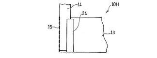
- FIG. 10 shows another modification of the electrode structure.
- the portion on the other end surface side in the width direction of the electrode lead 14 is fixed to the electrode 13 with the adhesive tape 24.
- the bonding strength between the electrode 13 and the electrode lead 14 can be further increased.
- the unevenness of the outer surface of the electrode structure can be reduced as compared with the case where the electrode lead 14 is fixed to the electrode 13 by the caulking portion 18. Therefore, it is possible to prevent the active material layer 12 on the surface of the electrode 13 from being damaged when the electrode 13 is formed by winding or laminating the electrode 13. As a result, inconveniences such as falling off of the active material are prevented. Therefore, it is possible to configure a high capacity nonaqueous electrolyte secondary battery electrode having a large reaction area.
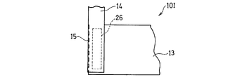
- FIG. 11 shows still another modification of the electrode structure.
- the portion of the electrode lead 14 that overlaps the electrode 13 is bonded to the electrode 13 with an adhesive 26.
- Example 8 An electrode structure having the same structure as that shown in FIG. 8A was produced as follows. In the same manner as in Example 1, a negative electrode 13 was produced. The electrode lead 14 is overlaid on the electrode 13 so that the end surface of one end in the longitudinal direction of the electrode 13 and the one end surface in the width direction of the electrode lead 14 are flush with each other, and the electrode 13 and the electrode 14 are fixed with a jig. did. And the joining part 15 was formed so that it might span between the end surface of the one end part of the longitudinal direction of the electrode 13, and the end surface of the width direction of the electrode lead 14 by plasma welding.
- Example 9 An electrode structure having the same structure as that shown in FIG. 10 was produced as follows. In the same manner as in Example 8, an electrode 13 as a negative electrode was produced, and a joint 15 was formed at one end in the longitudinal direction of the electrode 13. Thereafter, the portion on the other end surface side in the width direction of the electrode lead 14 was fixed to the electrode 13 with the adhesive tape 24.
- Example 10 A positive electrode structure having the same structure as that shown in FIG. 8A was produced as follows. In the same manner as in Example 7, a positive electrode 13 was produced. Then, using the electrode lead 14 made of aluminum, a joint 15 was formed at one end in the longitudinal direction of the electrode 13 in the same manner as in Example 8.
- Example 8 to 10 100 electrode structures of Examples 8 to 10 described above were produced. And about all the electrode structures, the electrical resistance between an electrode and an electrode lead was measured, and the average value was computed for every Example and the comparative example. Further, in order to examine the bonding strength between the electrode and the electrode lead, the tensile strength was measured by pulling the electrode lead in the direction along the main surface of the electrode while the electrode was fixed, and each example and comparative example The average value was calculated every time. The results are shown in Table 2.
- the tensile strength measured by the above-described method is required to be 10N or more.
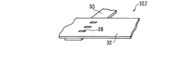
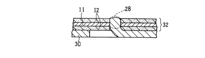
- FIG. 12 shows a schematic configuration of an electrode structure for a nonaqueous electrolyte secondary battery according to Embodiment 3 of the present invention.
- the same reference numerals are used for the same elements as in the first and second embodiments, and a detailed description thereof is omitted.
- the electrode lead 30 and the electrode 32 are joined by the joining portion 28 at an intermediate portion of the portion where the electrode lead 30 and the electrode 32 overlap.
- This joining method will be described below.
- the electrode lead 30 that is a constituent element of the electrode structure 10 ⁇ / b> J has a predetermined number (three in the illustrated example) of cut-and-raised portions 34 that are arranged in the longitudinal direction at predetermined intervals.
- the cut and raised portion 34 has a pointed shape such as a triangle.
- the electrode 32 has a predetermined number (three in the illustrated example) of slit-like through holes 36 arranged in the width direction at the same interval as the cut and raised portions 34.
- the through holes 36 can be formed by punching, for example, after the active material layer 12 is formed on both surfaces of the current collector 11. It can also be formed using a cutter.
- the joint portion 28 is formed in such a manner that the cut and raised portion 34 is melted by, for example, TIG welding in a state where the cut and raised portion 34 is inserted into the through hole 36 and then re-solidified.
- the current collector 11 and the electrode lead 30 are conducted by the joint portion 28, and the electrode lead 30 and the electrode 32 are joined.
- the electric resistance can be reduced.
- the exposed current collector 11 and the electrode lead 30 are part of the electrode lead 30 inside the slit-like through hole 36 provided in the electrode 32.
- the electrode lead 30 and the electrode 32 are joined to each other through the joint portion 28 made of the re-solidified body. Thereby, the electrode lead 30 and the electrode 32 can be connected without forming the exposed part of the collector 11 with a large area on the surface of the electrode 32.
- the cut-and-raised part 34 has a sharp tip, positioning when performing welding is facilitated. Further, since the volume of the cut-and-raised portion 34 is relatively small, it is possible to store all the joint portions 28 in the through holes 36. Therefore, it is possible to avoid the formation of irregularities, particularly convex portions, on the surface of the electrode 32. Further, the active material layer 12 is prevented from being damaged during welding. Further, the through-hole 36 can be formed in a very short time by punching or the like as compared with the case where the active material layer 12 is removed from the surface of the electrode 32 over a relatively large area. Therefore, productivity can be improved.
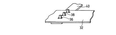
- the joint portion 42 is configured by a resolidified portion of the electrode lead 40.
- the cut-and-raised portion 38 of the electrode lead 40 is formed in a square shape, more specifically in a substantially positive direction or a substantially rectangular shape.
- the volume can be increased as compared with the cut-and-raised portion 34 of the electrode structure of FIG.
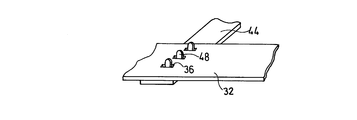
- the joint portion 46 is configured by a resolidified portion of the electrode lead 44.
- the cut-and-raised portion 48 of the electrode lead 44 has a rounded tip.
- the tip of the cut-and-raised part 48 in a round shape, when the cut-and-raised part 48 is melted by welding, it is possible to prevent melting residue from occurring and formation of burrs.
- the contact area between the current collector 11 and the joint 46 can be increased as compared with the case of FIG. Therefore, the electrical resistance can be reduced. Further, it is possible to avoid the formation of irregularities on the surface of the electrode 13.
- Example 11 An electrode structure having the same structure as that shown in FIG. 12 was produced as follows.
- a negative electrode 32 was produced in the same manner as in Example 1.
- Four slit-shaped through-holes 36 were formed by punching so as to be arranged in the width direction of the electrode 30 at intervals of 10 mm in a portion overlapping the electrode lead 30 of the electrode 32.
- the length of the through hole 36 was 2 mm, and the width was 0.1 mm.
- the same number of cut-and-raised portions 34 having the shape shown in FIG. 13 were formed at portions overlapping the electrodes 32 of the electrode leads 40 so as to be arranged at intervals of 10 mm in the longitudinal direction of the electrode leads 40.
- Example 12 A positive electrode structure having the same structure as that shown in FIG. 12 was produced as follows. In the same manner as in Example 7, a positive electrode 32 was produced. And the joining part 28 was formed like Example 11 using the electrode lead 14 comprised from aluminum.
- the cut-and-raised part 34 was melted by TIG welding and then re-solidified to connect the electrode 32 and the electrode lead 30.
- Example 11 and 12 100 electrode structures of Examples 11 and 12 were produced. And about all the electrode structures, the electrical resistance between an electrode and an electrode lead was measured, and the average value was computed for every Example. In addition, in order to examine the bonding strength between the electrode and the electrode lead, the tensile strength was measured by pulling the electrode lead in the direction along the main surface of the electrode with the electrode fixed, and the average value for each example. Was calculated. Moreover, the total thickness of the overlap part of an electrode and an electrode lead was measured, and the average value was computed for every Example. The results are shown in Table 3.
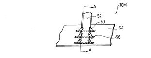
- FIG. 23 shows a schematic configuration of an electrode structure for a nonaqueous electrolyte secondary battery according to Embodiment 4 of the present invention.
- FIG. 24 shows a part of a cross section taken along line AA of FIG. 23 and 24, the same reference numerals are used for the same elements as in the first to third embodiments, and detailed description thereof is omitted.
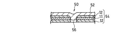
- the electrode lead 52 and the electrode 54 are joined by the joint portion 50 at an intermediate portion where the electrode lead 52 and the electrode 54 overlap each other.
- the strip-shaped electrode lead 52 is arranged so that the longitudinal direction is parallel to the width direction of the electrode 54 and a part thereof overlaps the electrode 54.
- the electrode 54 is formed with a plurality (three in the illustrated example) of slit-like through holes 56 parallel to the longitudinal direction of the electrode 54 so as to overlap the electrode lead 52 in the entire width.
- the length of the through hole 56 is larger than the width of the electrode lead 52.
- An end portion in the width direction of the electrode lead 52 is melted by, for example, plasma welding, and a part of the melted portion flows into the through hole 56 and re-solidifies.
- the current collector 11 and the electrode lead 52 may be made of the same material or different materials, but are preferably made of a metal having a very high binding property.
- the melted portion of the electrode lead 52 that has flowed into the through hole 56 becomes spherical due to surface tension at a location in contact with the current collector 11 and remains at that location.
- the electrode lead 52 and the current collector 11 are electrically connected to each other by the joint portion 54 made of the re-solidified body of the molten portion, so that reliable joining can be performed.
- the bonding portions 54 are formed alternately on the left and right sides in the width direction of the electrode leads 52.
- the electrode 54 and the electrode lead 52 can be joined without causing distortion in the longitudinal direction of the electrode 54.
- the method of melting the end portion of the electrode lead 52 in the width direction is not limited to plasma welding, and laser welding, TIG welding, electron beam welding, and other methods can be used.
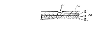
- the slit-like through hole 56 can be replaced with a recess 79.
- the recess 79 is formed so that the current collector 11 is exposed at the bottom.
- the end portion in the width direction of the electrode lead 52 is melted, and a part of the melted portion flows into the concave portion 79 and is solidified again, whereby the joint portion 50 is formed.
- the concave portion 79 instead of the through hole 56, the melted portion obtained by melting the end portion in the width direction of the electrode lead 52 is easily collected in the concave portion 79, and the current collector 11 and the electrode lead 52 are more reliably connected. Can be conducted.
- the cut surface of the current collector 11 by, for example, punching and the melted portion at the end in the width direction of the electrode lead 52 are in direct contact with each other, so that the metals are easily Since it couple
- the joint 50 is formed in the slit-like through hole 56 or the recess 79 formed in the electrode 54 so as to intersect with the end portion in the width direction of the electrode lead 52.
- the electrode lead 52 and the current collector 11 are brought into conduction, and the electrode 54 and the electrode lead 52 are joined. Thereby, the electrode lead 52 and the current collector 11 are reliably connected so that the metals are integrated. Therefore, the electrical resistance between the electrode 54 and the electrode lead 52 can be significantly reduced.
- the electrode lead 52 is attached to the electrode 54 within the range of the length of the through hole 56 or the recess 79.
- the mounting position can be adjusted freely. Therefore, attachment of the electrode lead 52 to the electrode 54 is facilitated, and productivity is improved.
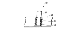
- FIG. 26 shows a modification of the electrode structure for a nonaqueous electrolyte secondary battery in FIG. Also in the electrode structure 10 ⁇ / b> N of this modified example, the joint portion 62 is formed in a slit-like through hole 60 (or a recess, the same applies hereinafter) formed in the electrode 58. However, in this modification, the through hole 60 is formed in parallel with the width direction of the electrode 58 so as to extend along both sides of the electrode lead 52.
- the through hole 60 is preferably provided at a position immediately adjacent to the side end of the electrode lead 52 or so that a part thereof overlaps the electrode lead 52. This is because if the through hole 60 and the electrode lead 52 are too far apart, the melted portion may not flow into the through hole 60. Moreover, even if the through hole 60 and the electrode lead 52 completely overlap, the same thing can occur.
- FIG. 27 shows another modification of the electrode structure. Also in the electrode structure 10 ⁇ / b> P of this modified example, the joint portion 64 is formed in a slit-like through hole 66 (or a recess, the same applies hereinafter) formed in the electrode 68. However, in this modification, the through hole 66 is formed obliquely with respect to the width direction or the longitudinal direction of the electrode 58.
- the joint portions 64 are spaced at appropriate intervals over the entire width of the electrode 68. Can be arranged. Thereby, when forming the electrode group by winding or laminating the electrode 68, it is possible to suppress the generation of wrinkles or the like in the electrode 68 and the separator. Further, even when the width of the electrode 68 and the length of the electrode lead 52 are changed by adjusting the inclination angle of the through hole 66, the entire width of the electrode 68 is not increased without increasing the number of the through holes 66. It becomes possible to arrange the joint portions 64 at appropriate intervals. Also in the electrode structure 10 ⁇ / b> P of FIG. 27, it is preferable that the joint portions 64 are alternately formed on the left and right in the width direction of the electrode lead 52.
- Example 13 An electrode structure having the same structure as that shown in FIG. 23 was produced as follows. Here, a recess 79 as shown in FIG. In the same manner as in Example 1, a negative electrode 54 was produced. Three slit-shaped concave portions 79 parallel to the longitudinal direction of the electrode were formed at predetermined positions in the longitudinal direction of the electrode 54 so as to be arranged at a predetermined interval (specifically, 10 mm) in the width direction of the electrode. . The recess 79 was formed so that the current collector 11 was exposed at the bottom. The length of the recess 79 was 5 mm. As the electrode lead 52, a copper lead having a width of 4 mm and a thickness of 0.1 mm was used.
- the electrode lead 52 was overlapped with the electrode 54 so as to overlap the recess 79 over the entire width, and fixed with a jig so that the electrode lead 52 and the recess 79 were in close contact with each other. In this state, a portion that intersects with the concave portion 79 at the end in the width direction of the electrode lead 52 is melted by plasma welding, and a part of the molten portion is poured into the concave portion 79 and then re-solidified. And the electrode lead 52 were joined.
- Example 14 An electrode structure having the same structure as that shown in FIG. 23 was produced as follows. Here, the through-hole 56 as shown in FIG. 24 was formed in the electrode. In the same manner as in Example 1, a negative electrode 54 was produced. Three slit-like through holes 56 parallel to the longitudinal direction of the electrode are formed at predetermined positions in the longitudinal direction of the electrode 54 so as to be arranged at a predetermined interval (specifically, 10 mm) in the width direction of the electrode. did. The length of the through hole 56 was 5 mm. As the electrode lead 52, a copper lead having a width of 4 mm and a thickness of 0.1 mm was used.
- the electrode lead 52 was overlapped with the electrode 54 so as to overlap the through hole 56 over the entire width, and fixed with a jig so that the electrode lead 52 and the through hole 56 were in close contact with each other. In that state, the portion that intersects the through hole 56 at the end in the width direction of the electrode lead 52 is melted by plasma welding, and a part of the melted portion is poured into the through hole 56 and then re-solidified. The electrode 54 and the electrode lead 52 were joined.
- Example 15 A positive electrode structure having the same structure as shown in FIG. 23 was produced as follows. Here, a recess 79 as shown in FIG. 25 was formed in the electrode. In the same manner as in Example 7, a positive electrode 54 was produced. Using the electrode 54 and the electrode lead 52 made of aluminum, an electrode structure was constructed in the same manner as in Example 13.
- the electrical resistance between the electrode 54 and the electrode lead 52 is small. This is because the current collector 11 exposed inside the through hole 56 or the recess 79 and the electrode lead 52 can be electrically connected to each other by the joint portion 50 and the electrode 54 and the electrode lead 52 can be connected. It is shown that.
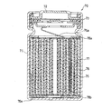
- FIG. 28 shows an example of such a nonaqueous electrolyte secondary battery.
- a positive electrode 75 in which an active material layer including a lithium composite oxide as a positive electrode active material is formed, and an active material layer including a material capable of holding lithium as a negative electrode active material is formed.
- the negative electrode 76 includes an electrode group 80 wound in a spiral shape with a separator 77 interposed therebetween.
- the positive electrode lead 75a is bonded to the positive electrode 75 in any one of the first to fourth embodiments described above, and the negative electrode lead 76a is connected to the negative electrode 76 in any one of the first to fourth embodiments described above. Are joined.
- the electrode group 80 is housed inside a bottomed cylindrical battery case 71 with the insulating plates 78a and 78b arranged on the top and bottom.
- the negative electrode lead 76 a led out from the lower part of the electrode group 80 is connected to the bottom of the battery case 71.
- the positive electrode lead 75 a led out from the upper part of the electrode group 80 is connected to a sealing body 72 that seals the opening of the battery case 71.
- a predetermined amount of non-aqueous electrolyte (not shown) is injected into the battery case 71.
- the electrolytic solution is injected after the electrode group 80 is stored in the battery case 71.
- a lithium ion secondary battery 70 is configured.
- the electrode structure of the present invention even in an electrode in which an active material is supported on the entire surface of both main surfaces of the current collector, the electric resistance is small without almost removing the active material from the surface of the current collector. In addition, it is possible to realize the bonding between the current collector and the electrode lead. Therefore, a high-capacity electrode can be realized, and a non-aqueous electrolyte secondary battery that is optimal as a power source for high-performance electronic devices and portable electronic devices that are becoming more compact can be realized.
- Electrode structure 11 Current collector 12 Active material layer 13, 32, 54, 58, 68 Electrode 14, 30, 40, 44, 52 Electrode lead 15, 28, 42, 46, 50, 62, 64 Joint 16 Stepped portion 18 Caulking portion 20, 24 Adhesive tape 22, 26 Adhesive 34, 38, 48 Cut and raised portion 36, 56, 60, 66 Through hole 70 Nonaqueous electrolyte secondary battery 71 Battery case 72 Sealing body 75 Positive electrode 75a Positive electrode Lead 76 Negative electrode 76a Negative electrode lead 77 Separator 79 Recess 80 Electrode group
Abstract
Description
電極リードと、
前記電極の端部、前記電極を貫通する貫通孔、および前記電極のいずれかの主面から前記活物質層を取り除くようにして設けられた凹部、の少なくとも1つにおいて、露出している集電体と、前記電極リードとを導通させるように、前記電極と前記電極リードとを接合する接合部と、
を備える非水電解質二次電池用電極構造体を提供する。
前記電極と重なり合う重なり部、および
前記電極の幅方向の一端部の端面と面一となるように配される一端面、を有し、
前記接合部が、前記電極の幅方向の一端部の端面と、前記電極リードの一端面との間に掛け渡されるようにして設けられる。
前記他端部に形成された接合部が、前記電極の幅方向の他端部において露出している集電体と、前記電極リードの段差部とを接合している。
前記電極リードの一端面と、前記電極の一端部の端面とが対向配置されている。
前記電極と重なり合う重なり部、および
前記電極の長手方向の一端部の端面と面一となるように配される一端面、を有し、
前記接合部が、前記電極の長手方向の一端部の端面と、前記電極リードの一端面との間に掛け渡されるようにして設けられている。
前記接合部は、前記貫通孔に挿入された前記切起部の再凝固体から構成されている。
前記接合部は、前記電極リードの端部の再凝固体から構成されており、前記スリット状の貫通孔または凹部の内部で露出している集電体と、前記電極リードとを接合している。
(b)前記電極の端部、前記電極を貫通する貫通孔、および前記電極のいずれかの主面から前記活物質層を取り除くようにして設けられた凹部、の少なくとも1つにおいて、露出している集電体と、前記電極リードとを導通させるように接合する接合部を形成する工程、を含む非水電解質二次電池用電極構造体の製造方法を提供する。
前記電極リードの一端面と前記電極の幅方向の一端面との間に掛け渡すように前記接合部を形成する工程、を含む。
前記電極の、前記電極リードの端部と重なる位置または隣接する位置にスリット状の前記貫通孔または凹部を形成する工程、および
前記電極リードの端部を溶融し、その溶融部分を前記スリット状の貫通孔または凹部の内部に流し込んだ後、再凝固させて、前記接合部を形成する工程、を含む。
前記正極および負極のそれぞれに接合される電極リード、
非水電解質、
前記電極群および前記非水電解質を収納する電池ケース、並びに
前記電池ケースの開口部を封口する封口体、を備え、
前記正極および負極のそれぞれに電極リードを接合して構成される各電極構造体の少なくとも一方が、上述した非水電解質二次電池用電極構造体から構成される非水電解質二次電池を提供する。
〈実施の形態1〉
図1Aおよび1Bに、本発明の実施の形態1に係る非水電解質二次電池用電極構造体の概略構成を、斜視図および断面図により示す。
図示例の電極構造体10は、リチウムイオン二次電池に代表される非水電解質二次電池に使用されるものであり、長尺帯状の金属箔からなる集電体11の両主面に全面的に活物質層12を形成して構成された電極13と、電極13を、非水電解質二次電池の外部端子(電池ケースおよび封口板等)と接続するための電極リード14とを含んでいる。
また、電極構造体10は、集電体11と電極リード14とを導通させながら、電極13と電極リード14とを接合する、所定数(図示例では2個)の接合部15をさらに含んでいる。
この変形例のように、電極13の幅方向の一端部および他端部の両方に接合部15を形成することで、電極13と電極リード14Aとの接合強度をより大きくすることが可能となる。
正極においては、特に限定されないが、正極集電体には、アルミニウムまたはアルミニウム合金製の箔を用いることができる。厚みは、5μm~50μmとすることができる。正極活物質層は、正極集電体の表面に正極合剤塗料を塗布し、乾燥した後、圧延して形成される。正極合剤塗料は、正極活物質、導電材および結着材を分散媒中にプラネタリーミキサ等の分散機により混合分散させることにより調製される。
正極用導電材としては、例えばアセチレンブラック、ケッチェンブラック、チャンネルブラック、ファーネスブラック、ランプブラック、サーマルブラック等のカーボンブラック、および各種グラファイトを単独あるいは組み合わせて用いることができる。
これらの方法により形成される活物質の薄膜の厚みは、作製される非水系二次電池の要求特性によっても異なるが、概ね5~30μmの範囲が好ましく、さらに10~25μmの範囲であることがより好ましい。
以下のようにして、図1Aに示したのと同じ構造の電極構造体を作製した。
厚さ26μmの銅箔を集電体11として使用した。その集電体11の両面に、真空蒸着により、Si(珪素)の酸化物からなる、厚みが20μmの活物質層12を形成した。活物質層12が両面に形成された集電体11を、長さ900mm、幅60mmの長尺帯状に裁断して、厚みが66μmである電極(負極)13を作製した。そして、幅4mm、厚さ0.1mmの電極リード14を、一部分を電極13と重ね合わせるように、かつ一端面が電極13の幅方向の一端部の端面と面一となるように配して、治具により固定した。電極リード14は、材質を銅とした。
次に、プラズマ溶接により、電極13の幅方向の一端部の端面と、電極リード14の一端面との間に掛け渡すように接合部15を形成して、電極13の幅方向の一端部の端面に露出している集電体11と電極リード14とを導通させた。
以下のようにして、図2に示したのと同じ構造の電極構造体を作製した。
実施例1と同様にして負極である電極13を作製した。電極リード14Aとして、その一端面から長さ60mmの位置の両側に、上記一端面と平行な部分の幅がそれぞれ1mmである段差部16を形成した。電極リード14Aの材質は実施例1の電極リード14と同じとした。
実施例1と同様にして、電極13の幅方向の一端部に接合部15を形成した後、両側の段差部16と、電極13の幅方向の他端部の端面との間に掛け渡すようにして接合部15を、プラズマ溶接により、それぞれ形成した。
以下のようにして、図3に示したのと同じ構造の電極構造体を作製した。
実施例1と同様にして、負極である電極13を作製し、電極13の幅方向の一端部に接合部15を形成した。その後、バーリング加工により、電極13を突き抜けるように電極リード14の一部分を立ち上げさせた。その後、電極13を突き抜けた、電極リード14の一部分を折り曲げるようにかしめて、3個のかしめ部18を形成した。
以下のようにして、図4に示したのと同じ構造の電極構造体を作製した。
実施例1と同様にして、負極である電極13を作製し、電極13の幅方向の一端部に接合部15を形成した。その後、接着テープ20を、電極リード14の電極13と接する側の面と、電極13の幅方向の他端部の端面との間に掛け渡すようにして貼着した。
以下のようにして、図5に示したのと同じ構造の電極構造体を作製した。
実施例1と同様にして、負極である電極13を作製し、電極13の幅方向の一端部に接合部15を形成した。その後、電極リード14の電極13と重なっている部分を、接着剤22により電極13に接着した。
以下のようにして、図6に示したのと同じ構造の電極構造体を作製した。
実施例1と同様にして、負極である電極13を作製し、電極13の幅方向の一端部に接合部15を形成した。その後、電極リード14の一端面と、電極13の幅方向の一端部の端面とを対向させるように、電極リード14を折り返した。
以下のようにして、図1Aに示したのと同じ構造の、正極の電極構造体を作製した。
厚さ20μmのアルミニウム箔を集電体11として使用した。活物質としてのコバルト酸リチウムと、導電材としてのアセチレンブラックと、結着材としてのポリフッ化ビニリデン(PVdF)とを混ぜ合わせて、正極合剤塗料を調製した。正極合剤塗料を、集電体11の両面に塗布し、乾燥した後、総厚みが100μmとなるまでプレスにより圧縮した。その後、長さ800mm、幅55mmの長尺帯状に裁断して、正極である電極13を作製した。そして、幅4mm、厚さ0.1mmの電極リード14を、一部分を電極13と重ね合わせるように、且つ一端面が電極13の幅方向の一端部の端面と面一となるように配して、治具により固定した。電極リード14は、材質をアルミニウムとした。
次に、プラズマ溶接により、電極13の幅方向の一端部の端面と、電極リード14の一端面との間に掛け渡すように接合部15を形成して、電極13の幅方向の一端部の端面に露出している集電体11と電極リード14とを導通させた。
実施例1と同様にして、負極である電極13を作製した。幅4mm、厚さ0.1mmの電極リード14の一部分を電極13に重ね合わせるように、その重なりの部分に接着剤を塗布して、電極13と電極リード14とを接着した。その後、上記重なりの部分を直径2mmの電極棒で上下から挟み込み、スポット溶接により、電極13と電極リード14とを接合しようと試みた。
実施例1と同様にして、負極である電極13を作製した。幅4mm、厚さ0.1mmの電極リード14の一部分を電極13に重ね合わせるように、その重なりの部分に接着剤を塗布して、電極13と電極リード14とを接着した。その後、上記重なりの部分を、超音波溶接用のアンビルとホーンとにより上下から挟み込み、超音波溶接により、電極13と電極リード14とを接合しようと試みた。
以下のようにして、図29に示したのと同じ構造の従来の電極構造体を作製した。
実施例1と同様にして電極103を作製した。電極103の長手方向の一端部の端面と、電極リード104の幅方向の一端面とが面一となるように、電極103に電極リード104を重ねて、電極103および電極104を治具により固定した。そして、バーリング加工により、電極103を突き抜けるように電極リード104の一部分を立ち上げさせた。その後、電極103を突き抜けた、電極リード104の一部分を折り曲げるようにして、かしめ部105を形成した。

これに対して、比較例1では、電極13の表面の活物質12には溶接電流が流れないために、スポット溶接により、電極13と電極リード14とを溶融接合することができず、電極13と電極リード14との間の導通を得ることができなかった。
同様に、比較例2においても、超音波溶接により、電極13と電極リード14とを溶融接合することができず、電極13と電極リード14との間の導通を得ることができなかった。これは活物質層12がSiの酸化物から構成されているためであり、超音波によっても、活物質層12を破壊することはできなかったことを示している。
また、比較例3は、かしめ部105のみで電極リードが電極に固定されているために、十分な強度が得られなかった。
また、電極13と電極リード14との重なり部がない実施例6は、総厚みが最小となった。
次に、本発明の実施の形態2を説明する。
図8Aおよび8Bに、本発明の実施の形態2に係る非水電解質二次電池用電極構造体の概略構成を、斜視図および断面図により示す。図8Aおよび8Bにおいて、実施の形態1と同一の要素には同一の符号を使用し、その詳細説明は省略する。
このように、接合部15により電極リード14を電極13に接合する一方で、電極13と電極リード14とが重なっている部分にかしめ部18を設けることで、電極13と電極リード14との接合強度をより大きくすることが可能となる。
以下のようにして、図8Aに示したのと同じ構造の電極構造体を作製した。
実施例1と同様にして、負極である電極13を作製した。電極13の長手方向の一端部の端面と、電極リード14の幅方向の一端面とが面一となるように、電極13に電極リード14を重ねて、電極13および電極14を治具により固定した。そして、プラズマ溶接により、電極13の長手方向の一端部の端面と、電極リード14の幅方向の一端面との間に掛け渡すようにして接合部15を形成した。
以下のようにして、図10に示したのと同じ構造の電極構造体を作製した。
実施例8と同様にして、負極である電極13を作製し、電極13の長手方向の一端部に接合部15を形成した。その後、接着テープ24により、電極リード14の幅方向の他端面側の部分を電極13に固定した。
以下のようにして、図8Aに示したのと同じ構造の、正極の電極構造体を作製した。
実施例7と同様にして、正極である電極13を作製した。そして、アルミニウムから構成される電極リード14を使用して、実施例8と同様にして、電極13の長手方向の一端部に接合部15を形成した。

次に、本発明の実施の形態3を説明する。
図12に、本発明の実施の形態3に係る非水電解質二次電池用電極構造体の概略構成を示す。図12において、実施の形態1および2と同一の要素には同一の符号を使用し、その詳細説明は省略する。
この接合方法を以下に説明する。
図13に示すように、電極構造体10Jの構成要素である電極リード30は、所定の間隔で長手方向に並ぶ、所定数(図示例では3個)の切り起こし部34を有している。切り起こし部34は、例えば三角形のような、先の尖った形状を有している。
これにより、電極32の表面に大面積の集電体11の露出部を形成することなく、電極リード30と電極32とを接続することができる。
また、溶接の際に活物質層12に損傷を与えることが防止される。
また、貫通孔36は、電極32の表面から比較的広い面積に亘って活物質層12を取り除く場合と比較して、ポンチ加工等により、極めて短時間で形成することができる。したがって、生産性を向上させることができる。
以下のようにして、図12に示したのと同じ構造の電極構造体を作製した。
実施例1と同様にして負極の電極32を作製した。電極32の電極リード30と重なる部分に、電極30の幅方向に10mmの間隔で並ぶように、スリット状の貫通孔36を、ポンチ加工により4個形成した。貫通孔36の長さは2mm、幅は0.1mmとした。
一方、電極リード40の電極32と重なる部分に、電極リード40の長手方向に10mmの間隔で並ぶように、図13に示した形状の切り起こし部34を同じ数だけ形成した。
以下のようにして、図12に示したのと同じ構造の、正極の電極構造体を作製した。
実施例7と同様にして、正極である電極32を作製した。そして、アルミニウムから構成される電極リード14を使用して、実施例11と同様にして、接合部28を形成した。

次に、本発明の実施の形態4を説明する。
図23に、本発明の実施の形態4に係る非水電解質二次電池用電極構造体の概略構成を示す。図24に、図23のA-A線における断面の一部分を示す。図23および24において、実施の形態1~3と同一の要素には同一の符号を使用し、その詳細説明は省略する。
短冊状の電極リード52は、長手方向が電極54の幅方向と平行となり、かつ一部分が電極54と重なるように配置される。
なお、電極リード52の幅方向の端部を溶融する方法は、プラズマ溶接に限らず、レーザ溶接、TIG溶接および電子ビーム溶接、並びにその他の方法とすることができる。
また、貫通孔66の傾斜の角度を調節することで、電極68の幅および電極リード52の長さが変化した場合にも、貫通孔66の本数を増やすことなく、電極68の全幅に亘って適度な間隔で、接合部64を配することが可能となる。
また、図27の電極構造体10Pにおいても、接合部64は、電極リード52の幅方向の左右交互に形成するのが好ましい。
以下のようにして、図23に示したのと同じ構造の電極構造体を作製した。ここでは、図25に示したような凹部79を電極54に形成した。
実施例1と同様にして、負極である電極54を作製した。その電極54の長手方向の所定位置に、電極の幅方向に所定の間隔(具体的には、10mm)で並ぶように、電極の長手方向と平行な3本のスリット状の凹部79を形成した。凹部79は、底に集電体11が露出するように形成した。凹部79の長さは5mmとした。
電極リード52は、幅が4mm、厚みが0.1mmの銅製のリードを使用した。
以下のようにして、図23に示したのと同じ構造の電極構造体を作製した。ここでは、図24に示したような貫通孔56を電極に形成した。
実施例1と同様にして、負極である電極54を作製した。その電極54の長手方向の所定位置に、電極の幅方向に所定の間隔(具体的には、10mm)で並ぶように、電極の長手方向と平行な3本のスリット状の貫通孔56を形成した。貫通孔56の長さは5mmとした。
電極リード52は、幅が4mm、厚みが0.1mmの銅製のリードを使用した。
以下のようにして、図23に示したのと同じ構造の、正極の電極構造体を作製した。ここでは、図25に示したような凹部79を電極に形成した。
実施例7と同様にして正極である電極54を作製した。その電極54およびアルミニウム製の電極リード52を使用して、実施例13と同様にして、電極構造体を構成した。

図28に、そのような非水電解質二次電池の一例を示す。図示例の二次電池70は、正極活物質としてのリチウム複合酸化物を含む活物質層が形成された正極75と、負極活物質としてのリチウムを保持しうる材料を含む活物質層が形成された負極76とを、セパレータ77を間に介在させて、渦巻状に巻回した電極群80を含んでいる。また、正極75には、上述した実施の形態1~4のいずれかの態様で正極リード75aが接合され、負極76には、上述した実施の形態1~4のいずれかの態様で負極リード76aが接合されている。
11 集電体
12 活物質層
13、32、54、58、68 電極
14、30、40、44、52 電極リード
15、28、42、46、50、62、64 接合部
16 段差部
18 かしめ部
20、24 接着テープ
22、26 接着剤
34、38、48 切り起こし部
36、56、60、66 貫通孔
70 非水電解質二次電池
71 電池ケース
72 封口体
75 正極
75a 正極リード
76 負極
76a 負極リード
77 セパレータ
79 凹部
80 電極群
Claims (26)
- 長尺帯状の金属箔からなる集電体、および前記集電体の両主面に形成された活物質層を含む電極と、
電極リードと、
前記電極の端部、前記電極を貫通する貫通孔、および前記電極のいずれかの主面から前記活物質層を取り除くようにして設けられた凹部、の少なくとも1つにおいて、前記集電体は露出部を有し、その露出部と、前記電極リードとを導通させるように、前記電極と前記電極リードとを接合する接合部と、
を備える非水電解質二次電池用電極構造体。 - 前記接合部が、前記電極の幅方向の一端部に形成されている請求項1記載の非水電解質二次電池用電極構造体。
- 前記電極リードが、
前記電極と重なり合う重なり部、および
前記電極の幅方向の一端部の端面と面一となるように配される一端面、を有し、
前記接合部が、前記電極の幅方向の一端部の端面と、前記電極リードの一端面との間に掛け渡されるようにして設けられる請求項2記載の非水電解質二次電池用電極構造体。 - 前記接合部が、前記電極の幅方向の他端部にも形成されている請求項3記載の非水電解質二次電池用電極構造体。
- 前記電極リードが、前記電極の幅方向の他端部の端面と面一に形成された段差部を有しており、
前記他端部に形成された接合部が、前記電極の幅方向の他端部において露出している集電体と、前記電極リードの段差部とを接合している請求項4記載の非水電解質二次電池用電極構造体。 - 前記電極リードと、前記電極の幅方向の他端部とが接着テープにより固定されている請求項3記載の非水電解質二次電池用電極構造体。
- 前記接合部が、前記電極リードの一端面と接触する第1接触部、前記電極の一端部の端面と接触する第2接触部、並びに前記第1接触部と第2接触部との間の折り返し部から構成されており、
前記電極リードの一端面と、前記電極の一端部の端面とが対向配置されている請求項2記載の非水電解質二次電池用電極構造体。 - 前記接合部が、前記電極の長手方向の一端部に形成されている請求項1記載の非水電解質二次電池用電極構造体。
- 前記電極リードが、
前記電極と重なり合う重なり部、および
前記電極の長手方向の一端部の端面と面一となるように配される一端面、を有し、
前記接合部が、前記電極の長手方向の一端部の端面と、前記電極リードの一端面との間に掛け渡されるようにして設けられている請求項8記載の非水電解質二次電池用電極構造体。 - 前記電極リードの他端部が、接着テープにより前記電極に固定されている請求項9記載の非水電解質二次電池用電極構造体。
- 前記電極リードは、その一部を切り起こした切起部を有し、
前記接合部は、前記貫通孔に挿入された前記切起部の再凝固体から構成されている請求項1記載の非水電解質二次電池用電極構造体。 - 前記電極リードの切起部は、先端が尖っている請求項11記載の非水電解質二次電池用電極構造体。
- 前記電極リードの切起部は、方形状である請求項11記載の非水電解質二次電池用電極構造体。
- 前記電極リードの切起部は、先端が丸まっている請求項11記載の非水電解質二次電池用電極構造体。
- 前記電極は、前記電極リードの端部と重なる位置または隣接する位置にスリット状の前記貫通孔または凹部が形成されており、
前記接合部は、前記電極リードの端部の再凝固体から構成されており、前記スリット状の貫通孔または凹部の内部で露出している集電体と、前記電極リードとを接合している請求項1記載の非水電解質二次電池用電極構造体。 - 前記スリット状の貫通孔または凹部が、前記電極の長手方向と平行に設けられている請求項15記載の非水電解質二次電池用電極構造体。
- 前記スリット状の貫通孔または凹部が、前記電極の長手方向と垂直に設けられている請求項15記載の非水電解質二次電池用電極構造体。
- 前記スリット状の貫通孔または凹部が、前記電極の長手方向に対して斜めに設けられている請求項15記載の非水電解質二次電池用電極構造体。
- 前記電極リードの一部を前記電極の厚み方向に貫通させてかしめたかしめ部を備える請求項1記載の非水電解質二次電池用電極構造体。
- 前記電極リードと、前記電極とが、互いに重なり合う重なり部において、接着剤により接着されている請求項1記載の非水電解質二次電池用電極構造体。
- (a)長尺帯状の金属箔からなる集電体の両主面に活物質層を形成した電極を準備する工程、並びに
(b)前記電極の端部、前記電極を貫通する貫通孔、および前記電極のいずれかの主面から前記活物質層を取り除くようにして設けられた凹部、の少なくとも1つにおいて、露出している集電体と、前記電極リードとを導通させるように接合する接合部を形成する工程、を含む非水電解質二次電池用電極構造体の製造方法。 - 前記工程bが、前記電極リードと、前記電極とを、少なくとも一部が互いに重なり合うように、且つ前記電極リードの一端面と前記電極の幅方向の一端面とが面一となるように、配置する工程、並びに
前記電極リードの一端面と前記電極の幅方向の一端面との間に掛け渡すように前記接合部を形成する工程、を含む請求項21記載の非水電解質二次電池用電極構造体の製造方法。 - 前記工程bが、さらに、前記電極リードの一端面と、前記電極の幅方向の一端面とを対向させるように、前記接合部を折り返す工程、を含む請求項22記載の非水電解質二次電池用電極構造体の製造方法。
- 前記工程bが、前記貫通孔に、前記電極リードの一部を切り起こした切起部を挿入した状態で、前記切起部を溶融し、再凝固させて、前記接合部を形成する工程、を含む請求項21記載の非水電解質二次電池用電極構造体の製造方法。
- 前記工程bが、
前記電極の、前記電極リードの端部と重なる位置または隣接する位置にスリット状の前記貫通孔または凹部を形成する工程、および
前記電極リードの端部を溶融し、その溶融部分を前記スリット状の貫通孔または凹部の内部に流し込んだ後、再凝固させて、前記接合部を形成する工程、を含む請求項21記載の非水電解質二次電池用電極構造体の製造方法。 - 長尺帯状の正極および負極を、間にセパレータを介在させて巻回または積層して構成された電極群、
前記正極および負極のそれぞれに接合される電極リード、
非水電解質、
前記電極群および前記非水電解質を収納する電池ケース、並びに
前記電池ケースの開口部を封口する封口体、を備え、
前記正極および負極のそれぞれに電極リードを接合して構成される各電極構造体の少なくとも一方が、請求項1記載の非水電解質二次電池用電極構造体から構成される非水電解質二次電池。
Priority Applications (2)
| Application Number | Priority Date | Filing Date | Title |
|---|---|---|---|
| CN200980117051.XA CN102027619B (zh) | 2008-06-25 | 2009-06-24 | 非水电解质二次电池用电极结构体、其制造方法及非水电解质二次电池 |
| US12/811,487 US8530084B2 (en) | 2008-06-25 | 2009-06-24 | Electrode structure for non-aqueous electrolyte secondary battery, method for producing the same, and non-aqueous electrolyte secondary battery |
Applications Claiming Priority (8)
| Application Number | Priority Date | Filing Date | Title |
|---|---|---|---|
| JP2008165563 | 2008-06-25 | ||
| JP2008165562 | 2008-06-25 | ||
| JP2008-165563 | 2008-06-25 | ||
| JP2008-165562 | 2008-06-25 | ||
| JP2008192979 | 2008-07-28 | ||
| JP2008-192979 | 2008-07-28 | ||
| JP2008307173 | 2008-12-02 | ||
| JP2008-307173 | 2008-12-02 |
Publications (1)
| Publication Number | Publication Date |
|---|---|
| WO2009157192A1 true WO2009157192A1 (ja) | 2009-12-30 |
Family
ID=41444265
Family Applications (1)
| Application Number | Title | Priority Date | Filing Date |
|---|---|---|---|
| PCT/JP2009/002889 WO2009157192A1 (ja) | 2008-06-25 | 2009-06-24 | 非水電解質二次電池用電極構造体、その製造方法、および非水電解質二次電池 |
Country Status (5)
| Country | Link |
|---|---|
| US (1) | US8530084B2 (ja) |
| JP (1) | JP5089656B2 (ja) |
| KR (1) | KR20100114934A (ja) |
| CN (1) | CN102027619B (ja) |
| WO (1) | WO2009157192A1 (ja) |
Cited By (1)
| Publication number | Priority date | Publication date | Assignee | Title |
|---|---|---|---|---|
| US20120135285A1 (en) * | 2010-11-25 | 2012-05-31 | Sony Corporation | Nonaqueous electrolyte battery |
Families Citing this family (16)
| Publication number | Priority date | Publication date | Assignee | Title |
|---|---|---|---|---|
| JP2014170614A (ja) * | 2011-06-29 | 2014-09-18 | Panasonic Corp | 電気化学素子用電極板および電気化学素子 |
| US9375804B2 (en) | 2011-07-27 | 2016-06-28 | GM Global Technology Operations LLC | Low pressure electron beam welding of Li-ion battery connections |
| US10446828B2 (en) * | 2011-10-21 | 2019-10-15 | Blackberry Limited | Recessed tab for higher energy density and thinner batteries |
| JP2015035249A (ja) * | 2011-11-28 | 2015-02-19 | パナソニック株式会社 | リチウムイオン電池用負極及びリチウムイオン電池 |
| JP2015035254A (ja) * | 2011-12-01 | 2015-02-19 | パナソニック株式会社 | 電気化学素子用電極板および電気化学素子 |
| KR101446160B1 (ko) * | 2012-12-07 | 2014-10-01 | 주식회사 엘지화학 | 테이프 처리된 전극조립체 및 이를 포함하는 전기화학소자 |
| JP6028916B2 (ja) * | 2012-12-18 | 2016-11-24 | 三菱自動車工業株式会社 | 二次電池 |
| KR102314084B1 (ko) * | 2014-04-04 | 2021-10-15 | 삼성에스디아이 주식회사 | 이차 전지 |
| US10147926B1 (en) * | 2014-04-15 | 2018-12-04 | Amazon Technologies, Inc. | Battery package including electrode having recessed region of electrode material layer exposing a portion of a conductive layer and method of making the same |
| TWI622214B (zh) * | 2016-09-22 | 2018-04-21 | 財團法人工業技術研究院 | 金屬離子二次電池 |
| JP2018067595A (ja) * | 2016-10-18 | 2018-04-26 | 太陽誘電株式会社 | 電気化学デバイス |
| US10944096B2 (en) * | 2018-04-10 | 2021-03-09 | GM Global Technology Operations LLC | Method of manufacturing a lithium metal negative electrode |
| US10919112B2 (en) * | 2018-04-30 | 2021-02-16 | GM Global Technology Operations LLC | Method and system for manufacturing a lithium metal negative electrode |
| CN113348573A (zh) * | 2019-01-29 | 2021-09-03 | 三洋电机株式会社 | 二次电池及其制造方法 |
| CN111740066B (zh) * | 2019-03-25 | 2023-05-12 | 宁德新能源科技有限公司 | 极片及具有所述极片的电极组件 |
| KR20210101520A (ko) | 2020-02-10 | 2021-08-19 | 주식회사 엘지에너지솔루션 | 접착부 및 스팟 용접으로 결합된 전극리드 결합부를 포함하는 전극조립체 및 이를 포함하는 파우치형 전지셀 |
Citations (4)
| Publication number | Priority date | Publication date | Assignee | Title |
|---|---|---|---|---|
| JP2001052679A (ja) * | 1999-08-03 | 2001-02-23 | Nec Corp | 非水電解液二次電池およびその製造方法 |
| JP2007141864A (ja) * | 2007-01-30 | 2007-06-07 | Sony Corp | 固体電解質電池およびその製造方法 |
| JP2007214086A (ja) * | 2006-02-13 | 2007-08-23 | Sony Corp | 電池用電極及びそれを用いた電池 |
| JP2008210617A (ja) * | 2007-02-26 | 2008-09-11 | Sony Corp | 電極構造体およびその製造方法、ならびに電池およびその製造方法 |
Family Cites Families (11)
| Publication number | Priority date | Publication date | Assignee | Title |
|---|---|---|---|---|
| JP2708123B2 (ja) | 1988-04-18 | 1998-02-04 | 東芝電池株式会社 | ペースト式電極の製造方法 |
| JPH02223153A (ja) * | 1989-02-23 | 1990-09-05 | Yuasa Battery Co Ltd | アルカリ蓄電池用極板 |
| JPH0513064A (ja) | 1991-07-02 | 1993-01-22 | Sanyo Electric Co Ltd | アルカリ蓄電池用電極板の製造方法 |
| JPH0562666A (ja) | 1991-08-29 | 1993-03-12 | Sanyo Electric Co Ltd | アルカリ蓄電池用非焼結式電極の製造方法 |
| JPH11283608A (ja) * | 1998-03-26 | 1999-10-15 | Tdk Corp | 電池用電極、その製造方法及び電池 |
| JP2000090994A (ja) | 1998-09-11 | 2000-03-31 | Matsushita Electric Ind Co Ltd | リード接合構造及びこの構造を用いた電池パック |
| US20030062259A1 (en) * | 1999-05-10 | 2003-04-03 | Naofumi Mushiake | Electrochemical device and process for manufacturing same |
| US7335448B2 (en) * | 2002-05-30 | 2008-02-26 | Matsushita Electric Industrial Co., Ltd. | Lithium ion secondary battery |
| JP4380201B2 (ja) | 2003-04-09 | 2009-12-09 | パナソニック株式会社 | 非水電解液二次電池の製造方法 |
| CN100541867C (zh) | 2004-04-13 | 2009-09-16 | 株式会社Lg化学 | 包括具有保护器元件的电极引线的电化学装置 |
| JP2007095445A (ja) * | 2005-09-28 | 2007-04-12 | Sanyo Electric Co Ltd | 非水電解質二次電池 |
-
2009
- 2009-06-24 JP JP2009149569A patent/JP5089656B2/ja not_active Expired - Fee Related
- 2009-06-24 KR KR1020107020681A patent/KR20100114934A/ko not_active Application Discontinuation
- 2009-06-24 WO PCT/JP2009/002889 patent/WO2009157192A1/ja active Application Filing
- 2009-06-24 CN CN200980117051.XA patent/CN102027619B/zh not_active Expired - Fee Related
- 2009-06-24 US US12/811,487 patent/US8530084B2/en not_active Expired - Fee Related
Patent Citations (4)
| Publication number | Priority date | Publication date | Assignee | Title |
|---|---|---|---|---|
| JP2001052679A (ja) * | 1999-08-03 | 2001-02-23 | Nec Corp | 非水電解液二次電池およびその製造方法 |
| JP2007214086A (ja) * | 2006-02-13 | 2007-08-23 | Sony Corp | 電池用電極及びそれを用いた電池 |
| JP2007141864A (ja) * | 2007-01-30 | 2007-06-07 | Sony Corp | 固体電解質電池およびその製造方法 |
| JP2008210617A (ja) * | 2007-02-26 | 2008-09-11 | Sony Corp | 電極構造体およびその製造方法、ならびに電池およびその製造方法 |
Cited By (2)
| Publication number | Priority date | Publication date | Assignee | Title |
|---|---|---|---|---|
| US20120135285A1 (en) * | 2010-11-25 | 2012-05-31 | Sony Corporation | Nonaqueous electrolyte battery |
| US10840555B2 (en) * | 2010-11-25 | 2020-11-17 | Murata Manufacturing Co., Ltd. | Nonaqueous electrolyte battery |
Also Published As
| Publication number | Publication date |
|---|---|
| JP5089656B2 (ja) | 2012-12-05 |
| US8530084B2 (en) | 2013-09-10 |
| US20100285353A1 (en) | 2010-11-11 |
| CN102027619A (zh) | 2011-04-20 |
| KR20100114934A (ko) | 2010-10-26 |
| CN102027619B (zh) | 2014-02-05 |
| JP2010157484A (ja) | 2010-07-15 |
Similar Documents
| Publication | Publication Date | Title |
|---|---|---|
| JP5089656B2 (ja) | 非水電解質二次電池用電極構造体、その製造方法、および非水電解質二次電池 | |
| JP5550923B2 (ja) | 角形二次電池の製造方法 | |
| EP2634843A1 (en) | Rectangular secondary battery | |
| JP5137516B2 (ja) | 密閉電池 | |
| JP6032628B2 (ja) | 薄型電池 | |
| JP2008166030A (ja) | 渦巻電極体の製造方法及びこれを用いた密閉型電池の製造方法 | |
| CN105932214A (zh) | 二次电池及其制造方法 | |
| JP2007214086A (ja) | 電池用電極及びそれを用いた電池 | |
| JP2010086780A (ja) | 角形二次電池 | |
| JP2009259697A (ja) | 電池およびその製造方法 | |
| JP5796497B2 (ja) | 電池 | |
| JP2000277154A (ja) | 非水電解液二次電池 | |
| JP6045286B2 (ja) | 円筒形蓄電素子 | |
| JP4168227B2 (ja) | 電池およびその製造方法 | |
| WO2020170598A1 (ja) | 電極板及びその製造方法、二次電池及びその製造方法 | |
| WO2013021640A1 (ja) | 電気化学素子用電極板およびその製造方法、ならびに電気化学素子 | |
| JP2007324015A (ja) | 二次電池およびその製造方法 | |
| JP3652550B2 (ja) | リチウム二次電池及びその製造方法 | |
| JP7316520B2 (ja) | 電池 | |
| JP2002050343A (ja) | 二次電池の製造方法および二次電池 | |
| JP2009037896A (ja) | 非水系二次電池用電極板およびその製造方法とこれを用いた非水系二次電池 | |
| JP2012043704A (ja) | 非水電解液電池 | |
| JP5954339B2 (ja) | 角形二次電池及びその製造方法 | |
| JP2009037894A (ja) | 非水系二次電池用電極板およびその製造方法とこれを用いた非水系二次電池 | |
| JP5641390B2 (ja) | 電池およびその製造方法 |
Legal Events
| Date | Code | Title | Description |
|---|---|---|---|
| WWE | Wipo information: entry into national phase |
Ref document number: 200980117051.X Country of ref document: CN |
|
| 121 | Ep: the epo has been informed by wipo that ep was designated in this application |
Ref document number: 09769902 Country of ref document: EP Kind code of ref document: A1 |
|
| WWE | Wipo information: entry into national phase |
Ref document number: 12811487 Country of ref document: US |
|
| ENP | Entry into the national phase |
Ref document number: 20107020681 Country of ref document: KR Kind code of ref document: A |
|
| NENP | Non-entry into the national phase |
Ref country code: DE |
|
| 122 | Ep: pct application non-entry in european phase |
Ref document number: 09769902 Country of ref document: EP Kind code of ref document: A1 |